WO2011125155A1 - Dispositif d'aide à la marche - Google Patents
Dispositif d'aide à la marche Download PDFInfo
- Publication number
- WO2011125155A1 WO2011125155A1 PCT/JP2010/056092 JP2010056092W WO2011125155A1 WO 2011125155 A1 WO2011125155 A1 WO 2011125155A1 JP 2010056092 W JP2010056092 W JP 2010056092W WO 2011125155 A1 WO2011125155 A1 WO 2011125155A1
- Authority
- WO
- WIPO (PCT)
- Prior art keywords
- unit
- replacement part
- user
- lower leg
- replacement
- Prior art date
- Legal status (The legal status is an assumption and is not a legal conclusion. Google has not performed a legal analysis and makes no representation as to the accuracy of the status listed.)
- Ceased
Links
Images
Classifications
-
- A—HUMAN NECESSITIES
- A61—MEDICAL OR VETERINARY SCIENCE; HYGIENE
- A61H—PHYSICAL THERAPY APPARATUS, e.g. DEVICES FOR LOCATING OR STIMULATING REFLEX POINTS IN THE BODY; ARTIFICIAL RESPIRATION; MASSAGE; BATHING DEVICES FOR SPECIAL THERAPEUTIC OR HYGIENIC PURPOSES OR SPECIFIC PARTS OF THE BODY
- A61H3/00—Appliances for aiding patients or disabled persons to walk about
-
- A—HUMAN NECESSITIES
- A61—MEDICAL OR VETERINARY SCIENCE; HYGIENE
- A61H—PHYSICAL THERAPY APPARATUS, e.g. DEVICES FOR LOCATING OR STIMULATING REFLEX POINTS IN THE BODY; ARTIFICIAL RESPIRATION; MASSAGE; BATHING DEVICES FOR SPECIAL THERAPEUTIC OR HYGIENIC PURPOSES OR SPECIFIC PARTS OF THE BODY
- A61H1/00—Apparatus for passive exercising; Vibrating apparatus; Chiropractic devices, e.g. body impacting devices, external devices for briefly extending or aligning unbroken bones
- A61H1/02—Stretching or bending or torsioning apparatus for exercising
- A61H1/0237—Stretching or bending or torsioning apparatus for exercising for the lower limbs
- A61H1/024—Knee
-
- A—HUMAN NECESSITIES
- A61—MEDICAL OR VETERINARY SCIENCE; HYGIENE
- A61H—PHYSICAL THERAPY APPARATUS, e.g. DEVICES FOR LOCATING OR STIMULATING REFLEX POINTS IN THE BODY; ARTIFICIAL RESPIRATION; MASSAGE; BATHING DEVICES FOR SPECIAL THERAPEUTIC OR HYGIENIC PURPOSES OR SPECIFIC PARTS OF THE BODY
- A61H2201/00—Characteristics of apparatus not provided for in the preceding codes
- A61H2201/01—Constructive details
- A61H2201/0192—Specific means for adjusting dimensions
-
- A—HUMAN NECESSITIES
- A61—MEDICAL OR VETERINARY SCIENCE; HYGIENE
- A61H—PHYSICAL THERAPY APPARATUS, e.g. DEVICES FOR LOCATING OR STIMULATING REFLEX POINTS IN THE BODY; ARTIFICIAL RESPIRATION; MASSAGE; BATHING DEVICES FOR SPECIAL THERAPEUTIC OR HYGIENIC PURPOSES OR SPECIFIC PARTS OF THE BODY
- A61H2201/00—Characteristics of apparatus not provided for in the preceding codes
- A61H2201/16—Physical interface with patient
- A61H2201/1602—Physical interface with patient kind of interface, e.g. head rest, knee support or lumbar support
- A61H2201/165—Wearable interfaces
-
- A—HUMAN NECESSITIES
- A61—MEDICAL OR VETERINARY SCIENCE; HYGIENE
- A61H—PHYSICAL THERAPY APPARATUS, e.g. DEVICES FOR LOCATING OR STIMULATING REFLEX POINTS IN THE BODY; ARTIFICIAL RESPIRATION; MASSAGE; BATHING DEVICES FOR SPECIAL THERAPEUTIC OR HYGIENIC PURPOSES OR SPECIFIC PARTS OF THE BODY
- A61H2201/00—Characteristics of apparatus not provided for in the preceding codes
- A61H2201/50—Control means thereof
- A61H2201/5058—Sensors or detectors
- A61H2201/5069—Angle sensors
Definitions
- the present invention relates to a walking assistance device that assists a person's walking, and more particularly, to a walking assistance device that is attached to a person's leg.
- Patent Document 1 JP-A-9-173398 discloses a walking assist device.
- the walking assist device is configured to be attachable to a person's leg and can assist a person's walking by adjusting the movement of the leg.
- the walking assist device includes a thigh unit disposed on the thigh, a lower leg unit disposed on the lower leg, a foot unit disposed on the foot, and a knee position joint unit that swingably connects the thigh unit and the lower leg unit. It has.
- this type of walking assistance device can be adjusted in size according to the body shape of the user wearing it. Therefore, for example, in the walking assist device of Patent Document 1, the length of the lower leg unit can be adjusted by fastening the upper part and the lower part of the lower leg unit with bolts and using the bolt hole as a long hole. It is configured. According to this configuration, the length of the lower leg unit can be finely adjusted according to the user's body shape.
- the above-described structure needs to form a long hole in the lower leg unit, and as a result, the strength of the lower leg unit is reduced.
- the direction in which the force is applied to the lower leg unit and the longitudinal direction of the elongated hole substantially match, if a strong force is applied to the lower leg unit, the bolt moves along the elongated hole, and the length of the lower leg unit Can change unintentionally.
- the present invention provides a technique that enables the size adjustment of the walking assistance device without requiring the formation of a long hole.
- the present invention is embodied in a walking assist device that assists the user in walking.
- the walking assist device includes a thigh unit disposed on the user's thigh, a thigh unit disposed on the user's lower leg, a foot unit disposed on the user's foot, and the thigh unit and the lower leg unit coupled to be swingable.
- a knee position joint unit, and an ankle position joint unit that swingably connects the lower leg unit and the foot unit.
- the lower leg unit has a first replacement part and a second replacement part extending along the user's lower leg, and each length of the first replacement part and the second replacement part is changed to one having a different length. Is adjustable.
- This walking assist device has a structure that adjusts the length of the lower leg unit by exchanging the first replacement part and the second replacement part. According to this structure, there is no need to form a long hole in the lower leg unit, and a decrease in strength of the lower leg unit can be avoided. Even if a strong force is applied to the lower leg unit, the length of the lower leg unit does not change, and the user's walking can be stably supported.
- the length of the lower leg unit can be adjusted in multiple stages by the combination of the first replacement part and the second replacement part. For example, when adjusting the length of the lower leg unit only with the first replacement part, 30 first replacement parts having different lengths are prepared in order to adjust the length of the lower leg unit to 30 levels. There is a need. On the other hand, according to the combination of the first replacement part and the second replacement part, as an example, ten first replacement parts having different lengths and three second replacement parts having different lengths are used. If a total of 13 replacement parts are prepared, the length of the lower leg unit can be adjusted to 30 levels.
- the first replacement part and the second replacement part described above can be formed of the same material, or can be formed of different materials.
- the replacement part with the higher density is replaced with the lower replacement part. It is preferable to make it shorter than the replacement part. That is, if the first replacement part has a higher density than the second replacement part, the first replacement part is preferably shorter than the second replacement part. According to this structure, the weight of the crus unit can be reduced, and the load on the user and the load applied to the knee position joint unit can be reduced.
- the first replacement part when the first replacement part has a higher density than the second replacement part, the first replacement part is preferably located closer to the knee position joint unit than the second replacement part.
- the center of gravity of the lower leg unit is located near the knee position joint unit, and the moment of inertia of the lower leg unit based on the knee position joint unit can be reduced. Thereby, the burden concerning a user and the load added to a knee position joint unit can be reduced.
- the first replacement part is preferably formed of metal
- the second replacement part is preferably formed of a fiber reinforced material. Since metal is generally easy to process, if the first replacement part is made of metal, many first replacement parts can be prepared at low cost. On the other hand, since the fiber reinforced material generally has a large specific strength, if the second replacement part is formed of the fiber reinforced material, the weight can be significantly reduced while securing the strength of the lower leg unit.
- first replacement parts and second replacement parts are generally difficult to process, providing a large number of second replacement parts made of fiber reinforced materials increases costs. Therefore, when preparing a plurality of first replacement parts and second replacement parts in order to adjust the length of the lower leg unit, it is difficult to process the first replacement parts formed of metal that is easy to process. It is preferable to prepare more than the second replacement part formed of a material. For example, when the length of the lower leg unit is adjusted to 30 levels, 10 first replacement parts and 3 second replacement parts are prepared rather than preparing 3 first replacement parts and 10 second replacement parts. Parts should be prepared. Accordingly, the first replacement part and the second replacement part for replacement can be prepared at a relatively low cost.
- the foot unit has a sole member disposed along the sole and a third replacement part extending from the sole member toward the ankle position joint unit, and replaces the third replacement part with a different length. Accordingly, it is preferable that the distance from the sole member to the ankle position joint unit can be adjusted. According to this structure, the position of the ankle position joint unit can be adjusted with respect to the user's ankle without forming a long hole in the foot unit.
- the present invention provides an adjustment method for adjusting the size of the walking assist device described above.
- This adjustment method includes a step of preparing a plurality of first replacement parts having different lengths, a plurality of second replacement parts having different lengths, and a plurality of first replacement parts according to a user's body shape. And a step of selecting one of the plurality of second replacement parts, and a step of assembling the lower leg unit of the walking assistance device using the selected first replacement part and second replacement part.
- the length of the lower leg unit can be adjusted in multiple stages by the combination of the first replacement part and the second replacement part to be selected, rather than the total number of prepared first replacement parts and second replacement parts. Can do.
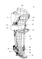
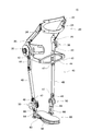
- the perspective view which shows the external appearance of a walking assistance apparatus The perspective view which shows the frame structure of a walking assistance apparatus.
- FIG. 1 is a perspective view illustrating a walking assist device 10 according to the embodiment.
- the walking assist device 10 is a device that is attached to the user's leg 100 and assists the user who is wearing it.
- the walking assist device 10 is used, for example, for function recovery training (rehabilitation) for a user who has difficulty in walking on his own.
- the walking assist device 10 is attached to a leg causing a user's functional disorder, and assists the user's walking by actively adjusting the movement of the leg.
- the walking assist device 10 includes a thigh unit 20 disposed on the user's thigh 102, a crus unit 40 disposed on the user's lower leg 104, and a foot unit 60 disposed on the user's foot 106. It has. Further, the walking assist device 10 includes a pair of knee position joint units 30 that connect the thigh unit 20 and the lower leg unit 40 so as to be swingable, and a pair that connects the lower leg unit 40 and the foot unit 60 so as to be swingable. The ankle position joint unit 50 is provided. The pair of knee position joint units 30 are arranged coaxially with the knee 103 with the user's knee 103 in between.
- one knee position joint unit 30 is disposed coaxially with the knee 103 on the outer side of the knee 103, and the other knee position joint unit 30 is disposed coaxially with the knee 103 on the inner side of the knee 103.
- the pair of ankle position joint units 50 is disposed coaxially with the ankle 105 with the ankle 105 of the user interposed therebetween. That is, one ankle position joint unit 50 is disposed coaxially with the ankle 105 outside the ankle 105, and the other ankle position joint unit 50 is disposed coaxially with the ankle 105 inside the ankle 105.
- the walking assist device 10 further includes a control unit 70, a drive unit 80, and a sensor unit 90.
- the control unit 70 is provided in the thigh unit 20, the drive unit 80 is provided in the knee position joint unit 30, and the sensor unit 90 is provided in the ankle position joint unit 50.
- the drive unit 80 incorporates a motor, a speed reducer, and sensors, and can drive the knee position joint unit 30. That is, the lower leg unit 40 can be swung with respect to the thigh unit 20.
- the sensor unit 90 has various sensors and can detect the angle of the ankle position joint unit 50 and whether the foot unit 60 is in contact with the ground.
- the control unit 70 includes a small computer and a battery, and is electrically connected to the drive unit 80 and the sensor unit 90.
- the control unit 70 inputs a detection signal from the sensor unit 90 and controls the operation of the drive unit 80 based on the input detection signal. Thereby, operation
- movement of the walking assistance apparatus 10 is adjusted with time according to a user's actual walk.
- FIG. 2 shows a perspective view of the frame structure of the walking assist device 10.
- the thigh unit 20 includes a thigh plate member 22, a pair of thigh pillar members 24, and a pair of thigh base members 26.
- the thigh plate member 22 is disposed in front of the user's thigh 102.
- the thigh plate member 22 is provided with a pad and a belt (not shown), and is firmly fixed to the user's thigh 102 by the belt.
- the user's thigh 102 is strongly tightened to the thigh plate member 22 by the belt.
- the user's thigh 102 is held immovable with respect to the thigh plate member 22 in any of the front-rear direction, the left-right direction, and the up-down direction.
- the thigh plate member 22 is supported by a pair of thigh pillar members 24.
- the thigh pillar member 24 is fixed to the thigh base member 26, and the thigh base member 26 is fixed to the knee position joint unit 30.
- the thigh plate member 22 and the thigh pillar member 24 of the present embodiment are formed of carbon fiber reinforced plastic (CFRP).
- CFRP carbon fiber reinforced plastic
- Carbon fiber reinforced plastic is a kind of fiber reinforced material and has high specific strength. Therefore, when the fiber reinforced material such as carbon fiber reinforced plastic is used, the thigh plate member 22 and the thigh pillar member 24 can be reduced in weight.
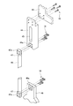
- FIG. 3 shows an exploded view of the frame structure of the lower leg unit 40.
- the crus unit 40 includes a pair of knee side base members 42, a knee plate member 43, a pair of first pillar members 44, a pair of second pillar members 46, and a pair of ankle side base members 48.
- the knee plate member 43 is disposed in front of the user's knee 103 and comes into contact with the lower part of the user's knee 103 (that is, the upper part of the lower leg 104) from the front.
- the knee plate member 43 is supported by a pair of knee-side base members 42.
- the crus unit 40 does not contact the user's crus 104 except for the knee plate member 43. That is, the user's lower leg 104 is held only from the front only by the knee plate member 43 of the lower leg unit 40.
- the knee base member 42 is an L-shaped plate member.
- the knee side base member 42 is made of a metal material, and more specifically is made of aluminum.
- One knee base member 42 is fixed to one knee position joint unit 30 outside the user's lower leg 104, and the other knee base member 42 is the other knee inside the user's lower leg 104. It is fixed to the position joint unit 30. That is, the knee-side base member 42 is swingably connected to the thigh base member 26 via the knee position joint unit 30.
- a knee plate member 43 is attached to an end portion located in front of the knee side base member 42.
- the first pillar member 44 is an elongated plate-like member.
- the first pillar member 44 is made of a metal material, and more specifically is made of aluminum.
- One first pillar member 44 is located outside the user's lower leg 104, and its upper end is fixed to one knee-side base member 42.
- the other first pillar member 44 is located inside the user's lower leg 104, and its upper end is fixed to the other knee-side base member 42.
- Each first pillar member 44 extends downward along the user's lower leg 104, and the upper end of the second pillar member 46 is fixed to the lower end thereof.
- the first pillar member 44 is a first replacement part that can be replaced according to the body shape of the user. That is, the walking assistance device 10 of the present embodiment can adjust the size (length) of the lower leg unit 40 by exchanging the first pillar member 44 with a different size (length).
- the second pillar member 46 is a rod-shaped member.
- the second pillar member 46 is formed of a fiber reinforced material, and more specifically is formed of carbon fiber reinforced plastic (CFRP).
- CFRP carbon fiber reinforced plastic
- metal fittings 47 made of a metal material (specifically, aluminum) are provided at both ends of the second pillar member 46.
- One second pillar member 46 is located outside the user's lower leg 104, and its upper end is fixed to one first pillar member 44.
- the other second pillar member 46 is located inside the user's lower leg 104, and its upper end is fixed to the other second pillar member 46.
- Each second pillar member 46 extends downward along the user's lower leg 104, and the lower end thereof is fixed to the ankle side base member 48.
- the second pillar member 46 is a second replacement part that can be replaced according to the body shape of the user. That is, the walking assistance device 10 of the present embodiment can adjust the size (length) of the crus unit 40 by replacing the second pillar member 46 with a different size (length).
- the ankle side base member 48 is a plate-like member.
- the ankle side base member 48 is made of a metal material, and more specifically is made of aluminum.
- One ankle side base member 48 is fixed to one ankle position joint unit 50 on the outside of the user's lower leg 104, and the other ankle side base member 48 is on the other side of the user's lower leg 104. It is fixed to the position joint unit 50.
- the first pillar member 44 and the second pillar member 46 are replacement parts that can be replaced according to the body shape of the user. Therefore, as shown in FIG. 3, the first pillar member 44 and the second pillar member 46 are fixed by bolts 12, 14, and 16, and are configured to be easily exchangeable.
- the upper end of the first pillar member 44 is fixed to the knee base member 42 by the plurality of bolts 12.
- the upper end of the second pillar member 46 is fixed to the lower end of the first pillar member 44 by a plurality of bolts 14.
- the lower end of the second pillar member 46 is fixed to the ankle side base member 48 by a plurality of bolts 14. Therefore, when the bolts 12, 14, 16 are removed, the first pillar member 44 and the second pillar member 46 can be exchanged.
- the second pillar member 46 is formed of CFRP. Therefore, metal fittings 47 for receiving the bolts 14 and 16 are provided at both ends of the second pillar member 46.
- the metal fitting 47 is provided with a tenon portion 47a protruding in a plate shape.
- the second pillar member 46 and the ankle side base member 48 are formed with tenon grooves 44a and 48a for receiving the tenon portion 47a, respectively. With this structure, the first pillar member 44 and the second pillar member 46 are firmly fixed without wobbling.
- the length of the lower leg unit 40 can be adjusted by exchanging the first pillar member 44 and the second pillar member 46. That is, a plurality of first pillar members 44 having different lengths and a plurality of second pillar members 46 having different lengths are prepared, and one first pillar member is selected according to the user's body shape. 44 and one second pillar member 46 are selected. Then, by assembling the crus unit 40 using the selected first pillar member 44 and one second pillar member 46, the crus unit 40 can be adjusted to a size corresponding to the body shape of the user. According to this structure, it is not necessary to form a long hole for size adjustment in the crus unit 40, and a decrease in strength of the crus unit 40 can be avoided. Even if a strong force is applied to the lower leg unit 40, the length of the lower leg unit 40 does not change. Therefore, it is possible to stably assist the user's walking.
- the length of the lower leg unit 40 can be adjusted in multiple stages by the combination of the first pillar member 44 and the second pillar member 46.
- the 30 first pillar members 44 having different lengths are arranged. It is necessary to prepare.
- the length of the crus unit 40 can be adjusted to 30 levels. In other words, the length of the crus unit 40 can be adjusted in multiple steps from the total number of the first pillar members 44 and the second pillar members 46 prepared.
- the first pillar member 44 is made of aluminum
- the second pillar member 46 is made of CFRP.
- aluminum has a density (specific gravity) larger than that of CFRP. Therefore, the first pillar member 44 having a high density is designed to be shorter than the second pillar member 46 having a low density.
- the weight unit 40 can be reduced in weight. That is, when the first pillar member 44 and the second pillar member 46 are formed of different materials, the one formed from a material having a high density is designed to be short, and the one formed from a material having a low density is designed to be long. 40 can be reduced in weight. Thereby, the burden concerning a user and the load added to the knee position joint unit 30 can be reduced.
- the first pillar member 44 made of aluminum is located closer to the knee position joint unit 30 than the second pillar member 46 made of CFRP. That is, the first pillar member 44 having a high density is positioned closer to the knee position joint unit 30 than the second pillar member 46 having a low density.
- the center of gravity of the crus unit 40 is located near the knee position joint unit 30, and the moment of inertia of the crus unit 40 with respect to the knee position joint unit 30 can be reduced.
- the knee position joint unit 30 is formed of a material having a higher density than that of a material having a lower density. The moment of inertia of the crus unit 40 with respect to the knee position joint unit 30 can be reduced. Thereby, the burden concerning a user and the load added to the knee position joint unit 30 can be reduced.
- the second pillar member 46 formed of CFRP can be manufactured at a relatively low cost. Therefore, when preparing the plurality of first pillar members 44 and the plurality of second pillar members 46, it is better to prepare more first pillar members 44 formed of aluminum than the second pillar members 46 formed of CFRP. . For example, when the length of the crus unit 40 is adjusted to 30 levels, ten first pillar members 44 and three are provided rather than three first pillar members 44 and ten second pillar members 46. The second pillar member 46 may be prepared. Thereby, the first pillar member 44 and the second pillar member 46 for replacement can be prepared at a relatively low cost.
- the foot unit 60 includes a sole plate member 62, a pair of foot pillar members 64, and a pair of foot base members 66.
- the sole plate member 62 is disposed below the user's foot 106, that is, on the sole of the user.
- the sole plate member 62 is configured to fix a user's shoes (not shown). Accordingly, the user's foot 106 is held immovably with respect to the sole plate member 62 in any of the front-rear direction, the left-right direction, and the up-down direction.
- the sole plate member 62 is provided with a position adjusting plate 63 extending to both sides thereof.
- the foot pillar member 64 is a plate-like member.
- the foot pillar member 64 is made of a metal material, and more specifically is made of aluminum.
- One foot pillar member 64 is fixed to the foot plate member 62 outside the user's foot 106, and the other foot pillar member 64 is fixed to the foot plate member 62 inside the user's foot 106.
- Each foot pillar member 64 is not directly fixed to the sole plate member 62 but is fixed to the position adjustment plate 63 of the sole plate member 62.
- Each foot pillar member 64 extends upward from the sole plate member 62, and its upper end is fixed to the foot base member 66.
- the foot base member 66 is an elongated block-shaped member.
- the foot base member 66 is made of a metal material, and more specifically is made of aluminum.
- One foot base member 66 is fixed to one ankle position joint unit 50 outside the user's foot 106, and the other foot base member 66 is connected to the other ankle position joint inside the user's foot 106. It is fixed to the unit 50. That is, the foot base member 66 is swingably connected to the ankle side base member 48 of the crus unit 40 by the ankle position joint unit 50.
- the foot pillar member 64 is a third replacement part that can be replaced according to the body shape of the user. That is, the walking assistance device 10 of the present embodiment can adjust the size of the foot unit 60 by replacing the foot pillar member 64 with a different size.
- the size of the foot unit 60 means the distance from the sole plate member 62 to the ankle position joint unit 50. That is, by replacing the foot pillar member 64, the position of the ankle position joint unit 50 with respect to the user's ankle 105 can be adjusted.
- the knee position joint unit 30 is configured as a pair, and each is positioned outside and inside the user's knee.
- the lower leg unit 40 includes a pair of first pillar members 44 and a pair of second pillar members 46.
- the upper ends of the first pillar members 44 are connected to the pair of knee position joint units 30 via the pair of knee base members 42, and the lower ends are the upper ends of the pair of second pillar members 46, respectively. It is linked to.
- the upper end of the crus unit 40 has a pair of knee-side base members 42 located on both sides of the user's knee and a knee plate member 43 that connects each of the pair of knee-side base members 42 through the front of the user's knee. It consists of The pair of knee-side base members 42 are arranged in parallel.
Landscapes
- Health & Medical Sciences (AREA)
- Epidemiology (AREA)
- Pain & Pain Management (AREA)
- Physical Education & Sports Medicine (AREA)
- Rehabilitation Therapy (AREA)
- Life Sciences & Earth Sciences (AREA)
- Animal Behavior & Ethology (AREA)
- General Health & Medical Sciences (AREA)
- Public Health (AREA)
- Veterinary Medicine (AREA)
- Rehabilitation Tools (AREA)
Abstract
La présente invention concerne un dispositif d'aide à la marche comprenant une unité de jambe supérieure placée sur la partie supérieure de la jambe de l'utilisateur ; une unité de jambe inférieure placée sur la partie inférieure de la jambe de l'utilisateur ; une unité de pied placée sur le pied de l'utilisateur ; une unité d'articulation du genou destinée à relier de manière pivotante l'unité de jambe supérieure à l'unité de jambe inférieure ; et une unité d'articulation de cheville destinée à relier de manière pivotante l'unité de jambe inférieure à l'unité de pied. Ladite unité de jambe inférieure possède un premier composant interchangeable et un second composant interchangeable qui s'étendent le long de la partie inférieure de la jambe de l'utilisateur, et l'unité de jambe inférieure est conçue de manière à ce que sa longueur puisse s'ajuster, lors d'un changement du premier composant interchangeable et/ou du second composant interchangeable, à un composant de longueur différente.
Priority Applications (5)
| Application Number | Priority Date | Filing Date | Title |
|---|---|---|---|
| CN201080031618.4A CN102470071B (zh) | 2010-04-02 | 2010-04-02 | 行走辅助装置 |
| PCT/JP2010/056092 WO2011125155A1 (fr) | 2010-04-02 | 2010-04-02 | Dispositif d'aide à la marche |
| JP2011526161A JP5170316B2 (ja) | 2010-04-02 | 2010-04-02 | 歩行補助装置 |
| EP10849399.0A EP2554150B1 (fr) | 2010-04-02 | 2010-04-02 | Dispositif d'aide à la marche |
| US13/242,220 US8439852B2 (en) | 2010-04-02 | 2011-09-23 | Walk assistance device |
Applications Claiming Priority (1)
| Application Number | Priority Date | Filing Date | Title |
|---|---|---|---|
| PCT/JP2010/056092 WO2011125155A1 (fr) | 2010-04-02 | 2010-04-02 | Dispositif d'aide à la marche |
Related Child Applications (1)
| Application Number | Title | Priority Date | Filing Date |
|---|---|---|---|
| US13/242,220 Continuation US8439852B2 (en) | 2010-04-02 | 2011-09-23 | Walk assistance device |
Publications (1)
| Publication Number | Publication Date |
|---|---|
| WO2011125155A1 true WO2011125155A1 (fr) | 2011-10-13 |
Family
ID=44762142
Family Applications (1)
| Application Number | Title | Priority Date | Filing Date |
|---|---|---|---|
| PCT/JP2010/056092 Ceased WO2011125155A1 (fr) | 2010-04-02 | 2010-04-02 | Dispositif d'aide à la marche |
Country Status (5)
| Country | Link |
|---|---|
| US (1) | US8439852B2 (fr) |
| EP (1) | EP2554150B1 (fr) |
| JP (1) | JP5170316B2 (fr) |
| CN (1) | CN102470071B (fr) |
| WO (1) | WO2011125155A1 (fr) |
Cited By (1)
| Publication number | Priority date | Publication date | Assignee | Title |
|---|---|---|---|---|
| JP2015181661A (ja) * | 2014-03-24 | 2015-10-22 | トヨタ自動車株式会社 | 歩行補助装置 |
Families Citing this family (12)
| Publication number | Priority date | Publication date | Assignee | Title |
|---|---|---|---|---|
| CN102885682B (zh) * | 2012-11-06 | 2014-05-28 | 中国科学院自动化研究所 | 康复机器人大腿长度调整装置 |
| CN115715736A (zh) * | 2013-11-29 | 2023-02-28 | 雷克斯生物有限公司 | 助行器 |
| KR102186859B1 (ko) | 2014-01-09 | 2020-12-04 | 삼성전자주식회사 | 보행 보조 기구 및 보행 보조 기구의 제어 방법 |
| CN104398368B (zh) * | 2014-12-10 | 2017-02-01 | 电子科技大学 | 一种电机横置的助行外骨骼机器人 |
| FR3034986B1 (fr) | 2015-04-16 | 2021-05-21 | Aplinov | Dispositif d'assistance aux deplacements |
| US10426637B2 (en) | 2015-05-11 | 2019-10-01 | The Hong Kong Polytechnic University | Exoskeleton ankle robot |
| CN105362036B (zh) * | 2015-10-20 | 2019-01-25 | 中国电子科技集团公司第二十一研究所 | 康复助力机械腿 |
| KR102646609B1 (ko) | 2016-09-07 | 2024-03-12 | 삼성전자주식회사 | 착용 모듈 및 이를 포함하는 운동 보조 장치 |
| IT201600099694A1 (it) * | 2016-10-05 | 2018-04-05 | Fondazione St Italiano Tecnologia | Esoscheletro per arti inferiori |
| KR102466581B1 (ko) * | 2017-03-07 | 2022-11-15 | 가부시키가이샤 사키마 기시 | 무릎/팔꿈치 관절 어시스트 장치 |
| JP7230786B2 (ja) | 2019-11-28 | 2023-03-01 | トヨタ自動車株式会社 | 脚装具及び脚装具を覆う衣服 |
| CN111920652B (zh) * | 2020-07-22 | 2021-06-18 | 燕山大学 | 可自适应调节脚踝承载力的辅助行走器 |
Citations (8)
| Publication number | Priority date | Publication date | Assignee | Title |
|---|---|---|---|---|
| JPS5551265U (fr) * | 1978-10-02 | 1980-04-04 | ||
| JPH0999123A (ja) * | 1995-10-06 | 1997-04-15 | Suzuki:Kk | パター |
| JPH09173398A (ja) | 1995-12-26 | 1997-07-08 | Technol Res Assoc Of Medical & Welfare Apparatus | 歩行補助装置 |
| JP2001055710A (ja) * | 1999-08-19 | 2001-02-27 | Tokyo Fabric Kogyo Kk | 連結式落橋防止装置 |
| JP2003220102A (ja) * | 2002-01-29 | 2003-08-05 | Hitachi Ltd | 動作支援装置 |
| JP2004344305A (ja) * | 2003-05-21 | 2004-12-09 | Honda Motor Co Ltd | 歩行補助装置 |
| JP2007130459A (ja) * | 2005-11-09 | 2007-05-31 | Kyu Dong Lim | 4軸補装具関節 |
| WO2010035706A1 (fr) * | 2008-09-26 | 2010-04-01 | 国立大学法人筑波大学 | Structure cadre de dispositif portable d'aide au mouvement |
Family Cites Families (8)
| Publication number | Priority date | Publication date | Assignee | Title |
|---|---|---|---|---|
| US5848979A (en) * | 1996-07-18 | 1998-12-15 | Peter M. Bonutti | Orthosis |
| CA2239144A1 (fr) * | 1998-06-08 | 1999-12-08 | Mission Sante Bois-Francs Inc. | Exerciseur orthopedique |
| JP4326259B2 (ja) * | 2003-05-21 | 2009-09-02 | 本田技研工業株式会社 | 歩行補助装置 |
| US7175602B2 (en) * | 2004-05-10 | 2007-02-13 | Robert Diaz | Portable therapy device |
| US7429253B2 (en) * | 2004-09-21 | 2008-09-30 | Honda Motor Co., Ltd. | Walking assistance system |
| JP4071755B2 (ja) | 2004-09-21 | 2008-04-02 | 本田技研工業株式会社 | 歩行補助装置 |
| AU2008341232B2 (en) * | 2007-12-26 | 2015-04-23 | Rex Bionics Limited | Mobility aid |
| JP5075759B2 (ja) | 2008-08-07 | 2012-11-21 | 本田技研工業株式会社 | 歩行補助装置 |
-
2010
- 2010-04-02 EP EP10849399.0A patent/EP2554150B1/fr not_active Not-in-force
- 2010-04-02 CN CN201080031618.4A patent/CN102470071B/zh not_active Expired - Fee Related
- 2010-04-02 WO PCT/JP2010/056092 patent/WO2011125155A1/fr not_active Ceased
- 2010-04-02 JP JP2011526161A patent/JP5170316B2/ja active Active
-
2011
- 2011-09-23 US US13/242,220 patent/US8439852B2/en not_active Expired - Fee Related
Patent Citations (8)
| Publication number | Priority date | Publication date | Assignee | Title |
|---|---|---|---|---|
| JPS5551265U (fr) * | 1978-10-02 | 1980-04-04 | ||
| JPH0999123A (ja) * | 1995-10-06 | 1997-04-15 | Suzuki:Kk | パター |
| JPH09173398A (ja) | 1995-12-26 | 1997-07-08 | Technol Res Assoc Of Medical & Welfare Apparatus | 歩行補助装置 |
| JP2001055710A (ja) * | 1999-08-19 | 2001-02-27 | Tokyo Fabric Kogyo Kk | 連結式落橋防止装置 |
| JP2003220102A (ja) * | 2002-01-29 | 2003-08-05 | Hitachi Ltd | 動作支援装置 |
| JP2004344305A (ja) * | 2003-05-21 | 2004-12-09 | Honda Motor Co Ltd | 歩行補助装置 |
| JP2007130459A (ja) * | 2005-11-09 | 2007-05-31 | Kyu Dong Lim | 4軸補装具関節 |
| WO2010035706A1 (fr) * | 2008-09-26 | 2010-04-01 | 国立大学法人筑波大学 | Structure cadre de dispositif portable d'aide au mouvement |
Non-Patent Citations (1)
| Title |
|---|
| See also references of EP2554150A4 * |
Cited By (1)
| Publication number | Priority date | Publication date | Assignee | Title |
|---|---|---|---|---|
| JP2015181661A (ja) * | 2014-03-24 | 2015-10-22 | トヨタ自動車株式会社 | 歩行補助装置 |
Also Published As
| Publication number | Publication date |
|---|---|
| EP2554150B1 (fr) | 2015-03-04 |
| JP5170316B2 (ja) | 2013-03-27 |
| US8439852B2 (en) | 2013-05-14 |
| US20120016277A1 (en) | 2012-01-19 |
| EP2554150A1 (fr) | 2013-02-06 |
| CN102470071A (zh) | 2012-05-23 |
| CN102470071B (zh) | 2016-08-17 |
| EP2554150A4 (fr) | 2013-10-23 |
| JPWO2011125155A1 (ja) | 2013-07-08 |
Similar Documents
| Publication | Publication Date | Title |
|---|---|---|
| JP5170316B2 (ja) | 歩行補助装置 | |
| CN101460118B (zh) | 步行辅助装置 | |
| US7524297B2 (en) | Walking assistance device provided with a force sensor | |
| JP5697947B2 (ja) | 下肢動作支援装置 | |
| US9156516B2 (en) | Two-wheeled battery-powered vehicle | |
| US11278465B2 (en) | Modular exoskeleton for example for spinal cord injured patients | |
| KR102292983B1 (ko) | 하지 외골격 로봇장치 | |
| JP2012125279A (ja) | 脚装具 | |
| JP2006334200A (ja) | 肢体アシスト装置および肢体アシストプログラム | |
| KR20110074876A (ko) | 보행 보조 장치 | |
| JP6713124B1 (ja) | 短下肢装具の後方支柱および短下肢装具 | |
| JP2003220102A (ja) | 動作支援装置 | |
| US20180360677A1 (en) | Exoskeleton with cambered wheels for human locomotion | |
| US8172243B2 (en) | Jogging stroller | |
| JP5381876B2 (ja) | 歩行補助装具の評価方法 | |
| CN114404232A (zh) | 一种用于下肢康复助行的辅助系统 | |
| KR102379474B1 (ko) | 발목 배측굴곡-외전의 보조를 통한 족하수 방지 능동형 단하지보조기 | |
| CN113730196A (zh) | 下肢外骨骼机器人 | |
| JP5370098B2 (ja) | 歩行補助装具 | |
| US20210197923A1 (en) | Foot propulsion assembly | |
| CN114533499A (zh) | 一种用于下肢辅助器械的控制系统及控制方法 | |
| JP6160415B2 (ja) | 歩行補助装置装着用の椅子 | |
| JP4666642B2 (ja) | 歩行補助装置 | |
| KR101497673B1 (ko) | 탑승형 2족 보행 보조기구 | |
| JP2012090758A (ja) | 脚装具 |
Legal Events
| Date | Code | Title | Description |
|---|---|---|---|
| WWE | Wipo information: entry into national phase |
Ref document number: 201080031618.4 Country of ref document: CN |
|
| WWE | Wipo information: entry into national phase |
Ref document number: 2011526161 Country of ref document: JP |
|
| 121 | Ep: the epo has been informed by wipo that ep was designated in this application |
Ref document number: 10849399 Country of ref document: EP Kind code of ref document: A1 |
|
| WWE | Wipo information: entry into national phase |
Ref document number: 2010849399 Country of ref document: EP |
|
| NENP | Non-entry into the national phase |
Ref country code: DE |