WO2011125478A1 - Dispositif d'alarme pour véhicule - Google Patents
Dispositif d'alarme pour véhicule Download PDFInfo
- Publication number
- WO2011125478A1 WO2011125478A1 PCT/JP2011/056755 JP2011056755W WO2011125478A1 WO 2011125478 A1 WO2011125478 A1 WO 2011125478A1 JP 2011056755 W JP2011056755 W JP 2011056755W WO 2011125478 A1 WO2011125478 A1 WO 2011125478A1
- Authority
- WO
- WIPO (PCT)
- Prior art keywords
- driver
- vehicle
- tactile
- warning device
- warning
- Prior art date
- Legal status (The legal status is an assumption and is not a legal conclusion. Google has not performed a legal analysis and makes no representation as to the accuracy of the status listed.)
- Ceased
Links
Images

Classifications
-
- B—PERFORMING OPERATIONS; TRANSPORTING
- B62—LAND VEHICLES FOR TRAVELLING OTHERWISE THAN ON RAILS
- B62D—MOTOR VEHICLES; TRAILERS
- B62D1/00—Steering controls, i.e. means for initiating a change of direction of the vehicle
- B62D1/02—Steering controls, i.e. means for initiating a change of direction of the vehicle vehicle-mounted
- B62D1/04—Hand wheels
- B62D1/046—Adaptations on rotatable parts of the steering wheel for accommodation of switches
-
- B—PERFORMING OPERATIONS; TRANSPORTING
- B62—LAND VEHICLES FOR TRAVELLING OTHERWISE THAN ON RAILS
- B62D—MOTOR VEHICLES; TRAILERS
- B62D15/00—Steering not otherwise provided for
- B62D15/02—Steering position indicators ; Steering position determination; Steering aids
- B62D15/029—Steering assistants using warnings or proposing actions to the driver without influencing the steering system
Definitions
- the present invention relates to a vehicle warning device that gives a predetermined warning to a driver of a vehicle through tactile sense.
- a vehicle warning device that warns a driver of a vehicle such as an automobile by a method other than vision in order to recognize abnormality or danger is known.
- Patent Document 1 describes a vehicle warning device that prompts a driver to perform a collision avoidance operation when there is a possibility of a collision.
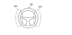
- This vehicle warning device detects the direction in which an obstacle is present with respect to the host vehicle, and if the host vehicle may collide with the obstacle, the vehicle steering device determines a predetermined steering handle according to the direction of the obstacle. Vibrate the part. Specifically, when the obstacle is located diagonally left forward with respect to the host vehicle, only the right side portion 101R of the steering handle 100 shown in FIG. 6 is vibrated, and the obstacle is diagonally forward right with respect to the host vehicle.
- both the right part 101R and the left part 101L of the steering handle 100 are vibrated.
- the vibration of the right side portion 101R and / or the left side portion 101L of the steering handle 100 is transmitted to the palm of the right and / or left hand of the driver, the arm muscles to which the vibration is transmitted reflexively contracts.
- the steering handle 100 is steered in the direction opposite to the obstacle to avoid a collision.
- the conventional vehicle warning device described above only transmits vibration to the right hand, left hand, or both to the driver. That is, the warning can be given to the driver only in three ways. Therefore, there is a problem that the amount of information that can be given to the driver is small.
- An object of the present invention is to provide a vehicular warning device capable of solving the above-described problems of the conventional vehicular warning device and giving a lot of information to the driver.
- the vehicle warning device is a vehicle warning device that gives a predetermined warning to a driver of the vehicle, and is provided at least two portions corresponding to two or more different parts of at least one hand of the driver.
- the control unit drives each of the at least two tactile units independently with a predetermined drive pattern according to the type of warning.
- the present invention at least two tactile units that are driven independently are provided corresponding to two or more different parts of at least one hand of the driver. Therefore, unlike the above-described conventional warning device that gives tactile stimulation to the whole of one hand, in the present invention, different tactile stimulation can be given to two or more different parts of one hand. Therefore, the number of arranged tactile units can be easily increased, and by increasing the number of tactile units, a lot of information can be given to the driver through the tactile units. Also, if the driving pattern for one tactile unit is changed according to the type of warning, different information can be given to the driver through this one tactile unit. Thus, the vehicle warning device of the present invention can give a lot of information to the driver.
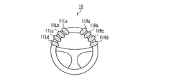
- FIG. 1 is a diagram schematically illustrating a steering handle of a vehicle on which a tactile unit that constitutes the vehicle warning device according to the first embodiment of the present invention is mounted.
- FIG. 2 is a diagram illustrating a schematic configuration of the tactile unit illustrated in FIG. 1.
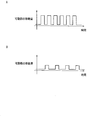
- 3A and 3B are diagrams showing examples of temporal changes in the amount of movement of the movable part of the tactile unit shown in FIG.
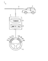
- FIG. 4 is a diagram showing a schematic configuration of the vehicle warning device according to the first embodiment of the present invention.
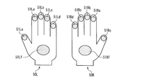
- FIG. 5 is a diagram showing an outline of a pair of gloves on which a tactile unit constituting the vehicle warning device according to the second embodiment of the present invention is mounted.
- FIG. 6 is a view showing a portion of a steering handle that is vibrated by a conventional vehicle warning device.
- the “vehicle” is not particularly limited, and includes all vehicles that are desired to warn a driver such as an automobile, a two-wheeled vehicle, a railway vehicle, etc., and among them, an automobile and a two-wheeled vehicle, particularly an automobile. preferable.
- Warning is performed to call attention to the driver of the vehicle, and the target is not particularly limited.
- the abnormality of itself, the abnormality in the external field of a vehicle, etc. can be illustrated.
- the at least two tactile units are provided on a handle of the vehicle. Since the driver always holds the handle while driving, the driver can be surely recognized the warning by providing a tactile sense unit on the handle.
- the at least two tactile units may be provided in a glove worn by a driver of the vehicle.
- the tactile unit is preferably provided on the glove.
- the driving pattern is defined by an intensity and a period for driving the tactile unit. More information can be provided to the driver by changing the intensity and period of driving the tactile unit. In addition, it becomes easy for the driver to intuitively recognize the importance of the warning.
- the at least two tactile units give vibration or electric stimulation to the driver's hand. Thereby, a driver
- the at least two tactile units include a solenoid coil. Thereby, it is possible to realize a tactile unit that is simple in structure, inexpensive and highly reliable.
- control unit includes a warning type database that stores an event that is a warning target for the driver.
- the event stored in the warning type database can be registered and / or deleted.
- the event to be warned can be freely set according to the driver, so that the warning can be customized.
- control unit includes a drive pattern database that stores the drive patterns.
- the drive pattern stored in the drive pattern database can be registered, changed, and / or deleted. Thereby, since a drive pattern can be changed according to a driver
- FIG. 1 is a diagram showing a schematic configuration of a steering handle (hereinafter simply referred to as “handle”) 10 of a vehicle equipped with a vehicle warning device according to Embodiment 1 of the present invention.
- the handle 10 includes tactile units 11Ra to 11Rd and tactile units 11La to 11Ld in the area held by the right and left hands of the driver.
- the tactile units 11Ra, 11Rb, 11Rc, and 11Rd are provided at positions where the index finger, middle finger, ring finger, and little finger of the driver's right hand are in contact with each other.
- the units 11La, 11Lb, 11Lc, and 11Ld are provided at positions where the index finger, middle finger, ring finger, and little finger of the driver's left hand touch each other.
- Each of the tactile units 11Ra to 11Rd and 11La to 11Ld gives a stimulus by vibration to the corresponding finger of the driver.
- the positions of the tactile units 11Ra to 11Rd and 11La to 11Ld may be freely adjustable on the handle 10 according to the position at which the driver usually holds the handle 10.
- the tactile units 11Ra to 11Rd and 11La to 11Ld include a solenoid coil 12, a movable portion 13 inserted into the solenoid coil 12, a spring having one end fixed to the fixed portion 15 and the other end fixed to the movable portion 13. 14.
- the movable part 13 is made of a material containing a magnetic material such as iron or nickel.
- the movable portion 13 moves from the stationary position in accordance with the change in current due to electromagnetic induction.
- the movable portion 13 vibrates up and down around the stationary position.
- the amplitude of the movable part 13 is proportional to the current.
- Such tactile units 11Ra to 11Rd and 11La to 11Ld are installed on the handle 10 so that the tip 13a of the movable portion 13 protruding from the solenoid coil 12 touches the driver's finger. Therefore, the driver can feel the vibration of the movable portion 13 through the finger.
- the movable part 13 is vibrated with different amplitudes, or the amplitude of the movable part 13 is periodically changed to change the vibration intensity of the movable part 13 at an arbitrary rhythm. Can be.
- FIG. 3A and 3B are diagrams showing an example of a temporal change in the movement amount (that is, the amplitude) of the movable portion 13.
- the moving amount of the movable part 13 is increased and the cycle in which the moving amount of the movable part 13 changes is shortened. it can.
- the moving amount of the movable part 13 may be reduced and the period of change of the moving amount of the movable part 13 may be increased. it can.
- the movable portion 13 can be vibrated in different vibration patterns by changing the magnitude of the amplitude of the movable portion 13 (that is, the strength of vibration) and the period of amplitude change (that is, variation of the vibration intensity).
- FIG. 4 is a diagram showing a schematic configuration of the vehicular warning device 1 according to the first embodiment.
- the vehicle warning device 1 includes a control board (control unit) 3 mounted on an automobile 2.
- the control board 3 is connected to a CAN (Controller Area Network) 4 of the automobile 2 and also connected to tactile units 11Ra to 11Rd and 11La to 11Ld of the handle 10.
- the control board 3 includes a warning type database 31 and a drive pattern database 32.
- the warning type database 31 stores in advance various events to be warned to the driver (this is called “warning target event”). Although there is no restriction
- the warning target event may be freely newly registered or deleted by the seller or driver (user) of the automobile 2.
- the drive pattern database 32 stores drive patterns of the tactile units 11Ra to 11Rd and 11La to 11Ld.
- the driving pattern is not particularly limited. For example, which of tactile units 11Ra to 11Rd and 11La to 11Ld is driven, the driving strength of the tactile unit to be driven, the period at which the driving strength of the tactile unit to be driven changes, etc. These conditions can be combined. These drive patterns may be freely newly registered, changed, or deleted by the seller or driver (user) of the automobile 2.
- Each driving pattern stored in the driving pattern database 32 is associated with each warning target event stored in the warning type database 31.
- the association between the warning target event and the driving pattern may be freely changeable by the seller of the automobile 2 or the driver (user).
- the control board 3 determines whether or not various abnormal signals received through the CAN 4 correspond to any of the warning target events stored in the warning type database 31. If the event corresponds to the warning target event, the drive pattern corresponding to the warning target event is read from the drive pattern database 32, and the tactile units 11Ra to 11Rd and 11La to 11Ld are driven with the drive pattern. The driver perceives the drive patterns of the tactile units 11Ra to 11Rd and 11La to 11Ld through the fingers of both hands, recognizes the contents of the warning target event from the drive patterns, and performs necessary operations.
- the tactile units 11Ra to 11Rd and 11La to 11Ld provided corresponding to each finger of the driver are independently driven with a predetermined driving pattern.
- 2 8 256 types of warnings can be performed by a combination of vibrating / not vibrating the eight tactile units 11Ra to 11Rd and 11La to 11Ld.
- a plurality of types of warnings can be issued through one tactile unit. Therefore, many kinds of warnings can be given to the driver by these combinations. For example, when there is a risk of collision with an obstacle right diagonally forward, all of the tactile units 11Ra to 11Rd corresponding to the right hand can be driven.
- the vibration intensity and the period of amplitude change of the tactile units 11Ra to 11Rd can be changed according to the distance to the obstacle, the relative speed with respect to the obstacle, and the like.
- more information can be given to the driver through the steering wheel 10 as compared with the conventional case.
- the second embodiment differs from the first embodiment in which the tactile unit is attached to the handle 10 in that the tactile unit is attached to a glove worn by the driver of the vehicle.
- the differences from the first embodiment will be described below.
- FIG. 5 is a diagram showing an outline of a pair of gloves 50R and 50L on which the tactile units constituting the vehicle warning device of the present embodiment are mounted.
- the right hand glove 50R is provided with tactile units 51Ra to 51Rf
- the left hand glove 50L is provided with tactile units 51La to 51Lf.
- the tactile units 51Ra, 51Rb, 51Rc, 51Rd, 51Re, and 51Rf are provided at positions where the index finger, middle finger, ring finger, pinky finger, thumb, and palm of the right hand touch when the driver wears the globe 50R on the right hand. Yes.
- the tactile units 51La, 51Lb, 51Lc, 51Ld, 51Le, and 51Lf are placed at positions where the index finger, middle finger, ring finger, little finger, thumb, and palm of the left hand touch when the driver wears the glove 50L on the left hand. Is provided.
- Each of the tactile units 51Ra to 51Rf and 51La to 51Lf gives a stimulus by vibration to a corresponding part of the driver's hand.
- the configurations of the tactile units 51Ra to 51Rf and 51La to 51Lf are not particularly limited, and may be the same as those of the first embodiment, for example.
- the tactile units 51Ra to 51Rf and 51La to 51Lf are independently driven in a predetermined drive pattern.
- 2 12 4096 kinds of warnings can be performed by a combination of vibrating / not vibrating twelve tactile units 51Ra to 51Rf and 51La to 51Lf.
- a plurality of types of warnings can be given through one tactile unit. Therefore, many kinds of warnings can be given to the driver by these combinations.
- more information can be given to the driver through the globes 50R and 50L as compared with the prior art.
- the tactile unit is mounted not on the handle but on the glove, even if the position where the driver grips the handle changes during driving, the driver can be surely recognized the warning.
- the second embodiment can be preferably applied as a warning device for two-wheeled vehicles that are often driven by wearing gloves.
- Embodiments 1 and 2 are merely examples, and the present invention is not limited to these, and can be freely modified and implemented.
- tactile units are provided for one hand, for a total of eight tactile units.
- six tactile units are provided for one hand, for a total of twelve tactile units.
- the number of tactile units is not limited to this, and may be more or less.
- a plurality of tactile units may be provided so as to correspond one-to-one to two or more different portions of at least one of the right hand and the left hand. Thereby, a driver
- the arrangement position of the tactile unit is not limited to the above embodiment.
- the tactile unit can be arranged so as to be in contact with an arbitrary part such as five fingers or the palm. Further, the driver or the like may be able to freely change the position of the tactile unit.
- the configuration of the tactile unit is not limited to FIG.
- a vibrator using a piezoelectric element, a vibrator having an eccentric weight attached to a rotating shaft of a small motor, or the like may be used.
- the stimulus given to the driver by the tactile unit need not be a vibration stimulus, and may be an electrical stimulus, for example.
- the tactile unit for applying electrical stimulation is not particularly limited, for example, the tactile unit can be configured by an electrode provided so as to touch the driver's hand so that a weak current flows in a specific part of the driver's hand. Even when an electrical stimulus is applied, the driver can be made to recognize many types of warnings by changing the drive pattern, that is, the change pattern of the voltage applied to the electrodes.
- the tactile unit when the tactile unit is mounted on the glove, it is desirable that the tactile unit be small, so that it is small using an electrode for applying electrical stimulation or a piezoelectric element for applying vibration stimulation. It is preferable to constitute a tactile unit.
- the present invention can be widely used as a warning device mounted on vehicles such as automobiles and motorcycles.
Landscapes
- Engineering & Computer Science (AREA)
- Chemical & Material Sciences (AREA)
- Combustion & Propulsion (AREA)
- Transportation (AREA)
- Mechanical Engineering (AREA)
- Steering Controls (AREA)
Abstract
L'invention porte sur un dispositif d'alarme (1) pour un véhicule, lequel dispositif comporte au moins deux unités tactiles (11Ra-11Rd, 11La-11Ld) conçues de façon à correspondre respectivement à deux ou plus de deux parties différentes d'au moins une main du conducteur. Une unité de commande (3) entraîne indépendamment chacune des deux unités tactiles selon le type d'alarme par un modèle de conduite prédéterminé. Suite à la configuration, un lot d'informations peut être donné au conducteur.
Priority Applications (1)
| Application Number | Priority Date | Filing Date | Title |
|---|---|---|---|
| US13/638,389 US20130021144A1 (en) | 2010-04-02 | 2011-03-22 | Alarm device for vehicle |
Applications Claiming Priority (2)
| Application Number | Priority Date | Filing Date | Title |
|---|---|---|---|
| JP2010086086 | 2010-04-02 | ||
| JP2010-086086 | 2010-04-02 |
Publications (1)
| Publication Number | Publication Date |
|---|---|
| WO2011125478A1 true WO2011125478A1 (fr) | 2011-10-13 |
Family
ID=44762433
Family Applications (1)
| Application Number | Title | Priority Date | Filing Date |
|---|---|---|---|
| PCT/JP2011/056755 Ceased WO2011125478A1 (fr) | 2010-04-02 | 2011-03-22 | Dispositif d'alarme pour véhicule |
Country Status (2)
| Country | Link |
|---|---|
| US (1) | US20130021144A1 (fr) |
| WO (1) | WO2011125478A1 (fr) |
Cited By (6)
| Publication number | Priority date | Publication date | Assignee | Title |
|---|---|---|---|---|
| JP2015221065A (ja) * | 2014-05-22 | 2015-12-10 | 株式会社デンソー | 歩行制御装置 |
| WO2016163085A1 (fr) * | 2015-04-07 | 2016-10-13 | 株式会社デンソー | Dispositif de fourniture d'informations |
| JP2019127152A (ja) * | 2018-01-24 | 2019-08-01 | Joyson Safety Systems Japan株式会社 | ステアリングホイール及び振動装置 |
| JP6723494B1 (ja) * | 2019-09-11 | 2020-07-15 | 三菱電機株式会社 | 情報提示装置、情報提示方法、及び、情報提示プログラム |
| JPWO2022107529A1 (fr) * | 2020-11-19 | 2022-05-27 | ||
| WO2023145166A1 (fr) * | 2022-01-26 | 2023-08-03 | 本田技研工業株式会社 | Véhicule de type à selle et système de stimulation tactile |
Families Citing this family (5)
| Publication number | Priority date | Publication date | Assignee | Title |
|---|---|---|---|---|
| US10994188B2 (en) * | 2015-11-30 | 2021-05-04 | Nike, Inc. | Shin guard with remote haptic feedback |
| US10780896B2 (en) | 2017-01-04 | 2020-09-22 | Joyson Safety Systems Acquisition Llc | Systems and methods of providing haptic feedback |
| DE102018209048B4 (de) * | 2018-06-07 | 2022-09-15 | Robert Bosch Gmbh | Verfahren zur haptischen Signalerzeugung für einen Fahrer eines Zweirads, Lenkergriff, Vibrationsvorrichtung, Lenker, Steuergerät und Zweirad |
| US12286187B2 (en) * | 2021-03-15 | 2025-04-29 | Honda Motor Co., Ltd. | Operation handle structure of device |
| US12673727B2 (en) * | 2021-07-21 | 2026-07-07 | Toyota Research Institute, Inc. | Directional vehicle steering cues |
Citations (9)
| Publication number | Priority date | Publication date | Assignee | Title |
|---|---|---|---|---|
| JPH11339580A (ja) * | 1998-05-22 | 1999-12-10 | Alps Electric Co Ltd | ステアリング装置 |
| JP2002298300A (ja) * | 2001-03-29 | 2002-10-11 | Denso Corp | 接近報知システム,搭載用報知装置,移動体及び人体装着用器具 |
| JP2008149844A (ja) * | 2006-12-15 | 2008-07-03 | Honda Motor Co Ltd | 車両の警報装置 |
| JP2008158671A (ja) * | 2006-12-21 | 2008-07-10 | Toyota Motor Corp | 車両用衝突警報装置 |
| JP2008162466A (ja) * | 2006-12-28 | 2008-07-17 | Toyoda Gosei Co Ltd | ステアリングホイール |
| JP2009001094A (ja) * | 2007-06-20 | 2009-01-08 | Tokai Rika Co Ltd | 操舵装置 |
| JP2010018204A (ja) * | 2008-07-11 | 2010-01-28 | Nippon Soken Inc | 情報提示装置および情報提示システム |
| JP2010173514A (ja) * | 2009-01-30 | 2010-08-12 | Toyota Infotechnology Center Co Ltd | 情報伝達ステアリング装置 |
| JP2010269762A (ja) * | 2009-05-25 | 2010-12-02 | Toyota Motor Corp | 車両用ステアリングシステム |
Family Cites Families (6)
| Publication number | Priority date | Publication date | Assignee | Title |
|---|---|---|---|---|
| JP3763418B2 (ja) * | 1997-09-25 | 2006-04-05 | 三菱電機株式会社 | リモコン装置 |
| JP2006119840A (ja) * | 2004-10-20 | 2006-05-11 | Hitachi Ltd | 車両用警告装置 |
| US20080270074A1 (en) * | 2007-04-30 | 2008-10-30 | Caterpillar Inc. | User customized machine data acquisition system |
| US8248270B2 (en) * | 2009-04-09 | 2012-08-21 | Verne Nieves | Tactile warning system for a vehicle |
| US20100295707A1 (en) * | 2009-05-19 | 2010-11-25 | Brian Bennie | System and method for lane departure warning |
| US8514102B2 (en) * | 2010-01-14 | 2013-08-20 | Honeywell International Inc. | Aircraft navigation accuracy display system |
-
2011
- 2011-03-22 US US13/638,389 patent/US20130021144A1/en not_active Abandoned
- 2011-03-22 WO PCT/JP2011/056755 patent/WO2011125478A1/fr not_active Ceased
Patent Citations (9)
| Publication number | Priority date | Publication date | Assignee | Title |
|---|---|---|---|---|
| JPH11339580A (ja) * | 1998-05-22 | 1999-12-10 | Alps Electric Co Ltd | ステアリング装置 |
| JP2002298300A (ja) * | 2001-03-29 | 2002-10-11 | Denso Corp | 接近報知システム,搭載用報知装置,移動体及び人体装着用器具 |
| JP2008149844A (ja) * | 2006-12-15 | 2008-07-03 | Honda Motor Co Ltd | 車両の警報装置 |
| JP2008158671A (ja) * | 2006-12-21 | 2008-07-10 | Toyota Motor Corp | 車両用衝突警報装置 |
| JP2008162466A (ja) * | 2006-12-28 | 2008-07-17 | Toyoda Gosei Co Ltd | ステアリングホイール |
| JP2009001094A (ja) * | 2007-06-20 | 2009-01-08 | Tokai Rika Co Ltd | 操舵装置 |
| JP2010018204A (ja) * | 2008-07-11 | 2010-01-28 | Nippon Soken Inc | 情報提示装置および情報提示システム |
| JP2010173514A (ja) * | 2009-01-30 | 2010-08-12 | Toyota Infotechnology Center Co Ltd | 情報伝達ステアリング装置 |
| JP2010269762A (ja) * | 2009-05-25 | 2010-12-02 | Toyota Motor Corp | 車両用ステアリングシステム |
Cited By (15)
| Publication number | Priority date | Publication date | Assignee | Title |
|---|---|---|---|---|
| JP2015221065A (ja) * | 2014-05-22 | 2015-12-10 | 株式会社デンソー | 歩行制御装置 |
| WO2016163085A1 (fr) * | 2015-04-07 | 2016-10-13 | 株式会社デンソー | Dispositif de fourniture d'informations |
| JP2016199081A (ja) * | 2015-04-07 | 2016-12-01 | 株式会社日本自動車部品総合研究所 | 情報提供装置 |
| JP2019127152A (ja) * | 2018-01-24 | 2019-08-01 | Joyson Safety Systems Japan株式会社 | ステアリングホイール及び振動装置 |
| JP6723494B1 (ja) * | 2019-09-11 | 2020-07-15 | 三菱電機株式会社 | 情報提示装置、情報提示方法、及び、情報提示プログラム |
| WO2021048946A1 (fr) * | 2019-09-11 | 2021-03-18 | 三菱電機株式会社 | Dispositif de présentation d'informations, procédé de présentation d'informations et programme de présentation d'informations |
| JPWO2022107529A1 (fr) * | 2020-11-19 | 2022-05-27 | ||
| WO2022107529A1 (fr) * | 2020-11-19 | 2022-05-27 | 本田技研工業株式会社 | Dispositif de rapport d'informations pour véhicule |
| CN116529153A (zh) * | 2020-11-19 | 2023-08-01 | 本田技研工业株式会社 | 车辆的信息通知装置 |
| JP7331270B2 (ja) | 2020-11-19 | 2023-08-22 | 本田技研工業株式会社 | 車両の情報通知装置 |
| US12409848B2 (en) | 2020-11-19 | 2025-09-09 | Honda Motor Co., Ltd. | Vehicle information notification device |
| CN116529153B (zh) * | 2020-11-19 | 2026-04-07 | 本田技研工业株式会社 | 车辆的信息通知装置 |
| WO2023145166A1 (fr) * | 2022-01-26 | 2023-08-03 | 本田技研工業株式会社 | Véhicule de type à selle et système de stimulation tactile |
| JPWO2023145166A1 (fr) * | 2022-01-26 | 2023-08-03 | ||
| JP7683049B2 (ja) | 2022-01-26 | 2025-05-26 | 本田技研工業株式会社 | 鞍乗り型車両及び触覚刺激システム |
Also Published As
| Publication number | Publication date |
|---|---|
| US20130021144A1 (en) | 2013-01-24 |
Similar Documents
| Publication | Publication Date | Title |
|---|---|---|
| US20130021144A1 (en) | Alarm device for vehicle | |
| JP3858642B2 (ja) | 操作スイッチ装置 | |
| US11848665B2 (en) | Motorcycle with haptic braking hazard alert | |
| US8760248B2 (en) | Electromagnetic actuator and corresponding control device with haptic feedback | |
| US20050030166A1 (en) | Control element or switching element for vehicles | |
| CN108068828B (zh) | 用于驾驶系统控制的触觉反馈 | |
| JP2019197575A (ja) | 一つの制御装置及び触覚効果を利用可能なユーザインターフェースを使用して複数のディスプレイを制御するシステム並びに方法 | |
| US8532879B2 (en) | Information providing device for vehicle | |
| US20140371987A1 (en) | Reconfigurable steering wheel with visual feedback related to vehicle systems | |
| US7507921B2 (en) | Control device having a rotating actuator | |
| JP5079582B2 (ja) | タッチ式センサ | |
| CN104395129B (zh) | 用于汽车的驾驶员辅助系统的操纵系统和具有该操纵系统的汽车 | |
| JP2016510286A (ja) | ハンドル搭載型指示システム | |
| Ploch et al. | Haptic skin stretch on a steering wheel for displaying preview information in autonomous cars | |
| JP2009504466A5 (fr) | ||
| JP2009255609A (ja) | 遠隔操作装置 | |
| TW201718317A (zh) | 用於控制至少一台二輪車的車頭握把的方法與裝置 | |
| JP7749673B2 (ja) | 車両の性能属性を制御するシステム | |
| JP2010260439A (ja) | 車両用ステアリングシステム | |
| US9607490B2 (en) | Haptic device | |
| US9644984B2 (en) | Operating device for a motor vehicle | |
| JP2017030665A (ja) | 車両用操作装置 | |
| EP1939061A1 (fr) | Agencement de signalisation tactile pour avertir le conducteur d'un véhicule, ainsi qu'un dispositif de contrôle de direction d'un véhicule et système d'assistance à la conduite selon cet agencement | |
| JP2017502413A (ja) | 自動車両用の制御装置及び制御方法 | |
| Capa et al. | ROS2-based Gadgets for Motorcyclists |
Legal Events
| Date | Code | Title | Description |
|---|---|---|---|
| 121 | Ep: the epo has been informed by wipo that ep was designated in this application |
Ref document number: 11765379 Country of ref document: EP Kind code of ref document: A1 |
|
| WWE | Wipo information: entry into national phase |
Ref document number: 13638389 Country of ref document: US |
|
| NENP | Non-entry into the national phase |
Ref country code: DE |
|
| 122 | Ep: pct application non-entry in european phase |
Ref document number: 11765379 Country of ref document: EP Kind code of ref document: A1 |
|
| NENP | Non-entry into the national phase |
Ref country code: JP |