WO2011126032A2 - 真空ポンプ - Google Patents
真空ポンプ Download PDFInfo
- Publication number
- WO2011126032A2 WO2011126032A2 PCT/JP2011/058656 JP2011058656W WO2011126032A2 WO 2011126032 A2 WO2011126032 A2 WO 2011126032A2 JP 2011058656 W JP2011058656 W JP 2011058656W WO 2011126032 A2 WO2011126032 A2 WO 2011126032A2
- Authority
- WO
- WIPO (PCT)
- Prior art keywords
- rotor
- cylinder
- vacuum pump
- casing
- chamber
- Prior art date
- Legal status (The legal status is an assumption and is not a legal conclusion. Google has not performed a legal analysis and makes no representation as to the accuracy of the status listed.)
- Ceased
Links
Images

















Classifications
-
- F—MECHANICAL ENGINEERING; LIGHTING; HEATING; WEAPONS; BLASTING
- F04—POSITIVE - DISPLACEMENT MACHINES FOR LIQUIDS; PUMPS FOR LIQUIDS OR ELASTIC FLUIDS
- F04C—ROTARY-PISTON, OR OSCILLATING-PISTON, POSITIVE-DISPLACEMENT MACHINES FOR LIQUIDS; ROTARY-PISTON, OR OSCILLATING-PISTON, POSITIVE-DISPLACEMENT PUMPS
- F04C29/00—Component parts, details or accessories of pumps or pumping installations, not provided for in groups F04C18/00 - F04C28/00
- F04C29/0042—Driving elements, brakes, couplings, transmissions specially adapted for pumps
- F04C29/0078—Fixing rotors on shafts, e.g. by clamping together hub and shaft
-
- F—MECHANICAL ENGINEERING; LIGHTING; HEATING; WEAPONS; BLASTING
- F04—POSITIVE - DISPLACEMENT MACHINES FOR LIQUIDS; PUMPS FOR LIQUIDS OR ELASTIC FLUIDS
- F04C—ROTARY-PISTON, OR OSCILLATING-PISTON, POSITIVE-DISPLACEMENT MACHINES FOR LIQUIDS; ROTARY-PISTON, OR OSCILLATING-PISTON, POSITIVE-DISPLACEMENT PUMPS
- F04C25/00—Adaptations of pumps for special use of pumps for elastic fluids
- F04C25/02—Adaptations of pumps for special use of pumps for elastic fluids for producing high vacuum
-
- F—MECHANICAL ENGINEERING; LIGHTING; HEATING; WEAPONS; BLASTING
- F01—MACHINES OR ENGINES IN GENERAL; ENGINE PLANTS IN GENERAL; STEAM ENGINES
- F01C—ROTARY-PISTON OR OSCILLATING-PISTON MACHINES OR ENGINES
- F01C21/00—Component parts, details or accessories not provided for in groups F01C1/00 - F01C20/00
- F01C21/10—Outer members for co-operation with rotary pistons; Casings
-
- F—MECHANICAL ENGINEERING; LIGHTING; HEATING; WEAPONS; BLASTING
- F01—MACHINES OR ENGINES IN GENERAL; ENGINE PLANTS IN GENERAL; STEAM ENGINES
- F01C—ROTARY-PISTON OR OSCILLATING-PISTON MACHINES OR ENGINES
- F01C21/00—Component parts, details or accessories not provided for in groups F01C1/00 - F01C20/00
- F01C21/10—Outer members for co-operation with rotary pistons; Casings
- F01C21/104—Stators; Members defining the outer boundaries of the working chamber
-
- F—MECHANICAL ENGINEERING; LIGHTING; HEATING; WEAPONS; BLASTING
- F04—POSITIVE - DISPLACEMENT MACHINES FOR LIQUIDS; PUMPS FOR LIQUIDS OR ELASTIC FLUIDS
- F04C—ROTARY-PISTON, OR OSCILLATING-PISTON, POSITIVE-DISPLACEMENT MACHINES FOR LIQUIDS; ROTARY-PISTON, OR OSCILLATING-PISTON, POSITIVE-DISPLACEMENT PUMPS
- F04C18/00—Rotary-piston pumps specially adapted for elastic fluids
- F04C18/30—Rotary-piston pumps specially adapted for elastic fluids having the characteristics covered by two or more of groups F04C18/02, F04C18/08, F04C18/22, F04C18/24, F04C18/48, or having the characteristics covered by one of these groups together with some other type of movement between co-operating members
- F04C18/34—Rotary-piston pumps specially adapted for elastic fluids having the characteristics covered by two or more of groups F04C18/02, F04C18/08, F04C18/22, F04C18/24, F04C18/48, or having the characteristics covered by one of these groups together with some other type of movement between co-operating members having the movement defined in group F04C18/08 or F04C18/22 and relative reciprocation between the co-operating members
- F04C18/344—Rotary-piston pumps specially adapted for elastic fluids having the characteristics covered by two or more of groups F04C18/02, F04C18/08, F04C18/22, F04C18/24, F04C18/48, or having the characteristics covered by one of these groups together with some other type of movement between co-operating members having the movement defined in group F04C18/08 or F04C18/22 and relative reciprocation between the co-operating members with vanes reciprocating with respect to the inner member
- F04C18/3441—Rotary-piston pumps specially adapted for elastic fluids having the characteristics covered by two or more of groups F04C18/02, F04C18/08, F04C18/22, F04C18/24, F04C18/48, or having the characteristics covered by one of these groups together with some other type of movement between co-operating members having the movement defined in group F04C18/08 or F04C18/22 and relative reciprocation between the co-operating members with vanes reciprocating with respect to the inner member the inner and outer member being in contact along one line or continuous surface substantially parallel to the axis of rotation
-
- F—MECHANICAL ENGINEERING; LIGHTING; HEATING; WEAPONS; BLASTING
- F04—POSITIVE - DISPLACEMENT MACHINES FOR LIQUIDS; PUMPS FOR LIQUIDS OR ELASTIC FLUIDS
- F04C—ROTARY-PISTON, OR OSCILLATING-PISTON, POSITIVE-DISPLACEMENT MACHINES FOR LIQUIDS; ROTARY-PISTON, OR OSCILLATING-PISTON, POSITIVE-DISPLACEMENT PUMPS
- F04C18/00—Rotary-piston pumps specially adapted for elastic fluids
- F04C18/30—Rotary-piston pumps specially adapted for elastic fluids having the characteristics covered by two or more of groups F04C18/02, F04C18/08, F04C18/22, F04C18/24, F04C18/48, or having the characteristics covered by one of these groups together with some other type of movement between co-operating members
- F04C18/34—Rotary-piston pumps specially adapted for elastic fluids having the characteristics covered by two or more of groups F04C18/02, F04C18/08, F04C18/22, F04C18/24, F04C18/48, or having the characteristics covered by one of these groups together with some other type of movement between co-operating members having the movement defined in group F04C18/08 or F04C18/22 and relative reciprocation between the co-operating members
- F04C18/344—Rotary-piston pumps specially adapted for elastic fluids having the characteristics covered by two or more of groups F04C18/02, F04C18/08, F04C18/22, F04C18/24, F04C18/48, or having the characteristics covered by one of these groups together with some other type of movement between co-operating members having the movement defined in group F04C18/08 or F04C18/22 and relative reciprocation between the co-operating members with vanes reciprocating with respect to the inner member
- F04C18/3448—Rotary-piston pumps specially adapted for elastic fluids having the characteristics covered by two or more of groups F04C18/02, F04C18/08, F04C18/22, F04C18/24, F04C18/48, or having the characteristics covered by one of these groups together with some other type of movement between co-operating members having the movement defined in group F04C18/08 or F04C18/22 and relative reciprocation between the co-operating members with vanes reciprocating with respect to the inner member with axially movable vanes
-
- F—MECHANICAL ENGINEERING; LIGHTING; HEATING; WEAPONS; BLASTING
- F04—POSITIVE - DISPLACEMENT MACHINES FOR LIQUIDS; PUMPS FOR LIQUIDS OR ELASTIC FLUIDS
- F04C—ROTARY-PISTON, OR OSCILLATING-PISTON, POSITIVE-DISPLACEMENT MACHINES FOR LIQUIDS; ROTARY-PISTON, OR OSCILLATING-PISTON, POSITIVE-DISPLACEMENT PUMPS
- F04C29/00—Component parts, details or accessories of pumps or pumping installations, not provided for in groups F04C18/00 - F04C28/00
-
- F—MECHANICAL ENGINEERING; LIGHTING; HEATING; WEAPONS; BLASTING
- F04—POSITIVE - DISPLACEMENT MACHINES FOR LIQUIDS; PUMPS FOR LIQUIDS OR ELASTIC FLUIDS
- F04C—ROTARY-PISTON, OR OSCILLATING-PISTON, POSITIVE-DISPLACEMENT MACHINES FOR LIQUIDS; ROTARY-PISTON, OR OSCILLATING-PISTON, POSITIVE-DISPLACEMENT PUMPS
- F04C29/00—Component parts, details or accessories of pumps or pumping installations, not provided for in groups F04C18/00 - F04C28/00
- F04C29/0042—Driving elements, brakes, couplings, transmissions specially adapted for pumps
- F04C29/0085—Prime movers
-
- F—MECHANICAL ENGINEERING; LIGHTING; HEATING; WEAPONS; BLASTING
- F04—POSITIVE - DISPLACEMENT MACHINES FOR LIQUIDS; PUMPS FOR LIQUIDS OR ELASTIC FLUIDS
- F04C—ROTARY-PISTON, OR OSCILLATING-PISTON, POSITIVE-DISPLACEMENT MACHINES FOR LIQUIDS; ROTARY-PISTON, OR OSCILLATING-PISTON, POSITIVE-DISPLACEMENT PUMPS
- F04C29/00—Component parts, details or accessories of pumps or pumping installations, not provided for in groups F04C18/00 - F04C28/00
- F04C29/06—Silencing
-
- F—MECHANICAL ENGINEERING; LIGHTING; HEATING; WEAPONS; BLASTING
- F04—POSITIVE - DISPLACEMENT MACHINES FOR LIQUIDS; PUMPS FOR LIQUIDS OR ELASTIC FLUIDS
- F04C—ROTARY-PISTON, OR OSCILLATING-PISTON, POSITIVE-DISPLACEMENT MACHINES FOR LIQUIDS; ROTARY-PISTON, OR OSCILLATING-PISTON, POSITIVE-DISPLACEMENT PUMPS
- F04C29/00—Component parts, details or accessories of pumps or pumping installations, not provided for in groups F04C18/00 - F04C28/00
- F04C29/06—Silencing
- F04C29/061—Silencers using overlapping frequencies, e.g. Helmholtz resonators
-
- F—MECHANICAL ENGINEERING; LIGHTING; HEATING; WEAPONS; BLASTING
- F04—POSITIVE - DISPLACEMENT MACHINES FOR LIQUIDS; PUMPS FOR LIQUIDS OR ELASTIC FLUIDS
- F04C—ROTARY-PISTON, OR OSCILLATING-PISTON, POSITIVE-DISPLACEMENT MACHINES FOR LIQUIDS; ROTARY-PISTON, OR OSCILLATING-PISTON, POSITIVE-DISPLACEMENT PUMPS
- F04C29/00—Component parts, details or accessories of pumps or pumping installations, not provided for in groups F04C18/00 - F04C28/00
- F04C29/06—Silencing
- F04C29/063—Sound absorbing materials
-
- F—MECHANICAL ENGINEERING; LIGHTING; HEATING; WEAPONS; BLASTING
- F04—POSITIVE - DISPLACEMENT MACHINES FOR LIQUIDS; PUMPS FOR LIQUIDS OR ELASTIC FLUIDS
- F04C—ROTARY-PISTON, OR OSCILLATING-PISTON, POSITIVE-DISPLACEMENT MACHINES FOR LIQUIDS; ROTARY-PISTON, OR OSCILLATING-PISTON, POSITIVE-DISPLACEMENT PUMPS
- F04C29/00—Component parts, details or accessories of pumps or pumping installations, not provided for in groups F04C18/00 - F04C28/00
- F04C29/06—Silencing
- F04C29/068—Silencing the silencing means being arranged inside the pump housing
-
- F—MECHANICAL ENGINEERING; LIGHTING; HEATING; WEAPONS; BLASTING
- F04—POSITIVE - DISPLACEMENT MACHINES FOR LIQUIDS; PUMPS FOR LIQUIDS OR ELASTIC FLUIDS
- F04C—ROTARY-PISTON, OR OSCILLATING-PISTON, POSITIVE-DISPLACEMENT MACHINES FOR LIQUIDS; ROTARY-PISTON, OR OSCILLATING-PISTON, POSITIVE-DISPLACEMENT PUMPS
- F04C29/00—Component parts, details or accessories of pumps or pumping installations, not provided for in groups F04C18/00 - F04C28/00
- F04C29/12—Arrangements for admission or discharge of the working fluid, e.g. constructional features of the inlet or outlet
-
- F—MECHANICAL ENGINEERING; LIGHTING; HEATING; WEAPONS; BLASTING
- F04—POSITIVE - DISPLACEMENT MACHINES FOR LIQUIDS; PUMPS FOR LIQUIDS OR ELASTIC FLUIDS
- F04D—NON-POSITIVE-DISPLACEMENT PUMPS
- F04D19/00—Axial-flow pumps
-
- F—MECHANICAL ENGINEERING; LIGHTING; HEATING; WEAPONS; BLASTING
- F04—POSITIVE - DISPLACEMENT MACHINES FOR LIQUIDS; PUMPS FOR LIQUIDS OR ELASTIC FLUIDS
- F04D—NON-POSITIVE-DISPLACEMENT PUMPS
- F04D19/00—Axial-flow pumps
- F04D19/02—Multi-stage pumps
- F04D19/04—Multi-stage pumps specially adapted to the production of a high vacuum, e.g. molecular pumps
-
- B—PERFORMING OPERATIONS; TRANSPORTING
- B60—VEHICLES IN GENERAL
- B60T—VEHICLE BRAKE CONTROL SYSTEMS OR PARTS THEREOF; BRAKE CONTROL SYSTEMS OR PARTS THEREOF, IN GENERAL; ARRANGEMENT OF BRAKING ELEMENTS ON VEHICLES IN GENERAL; PORTABLE DEVICES FOR PREVENTING UNWANTED MOVEMENT OF VEHICLES; VEHICLE MODIFICATIONS TO FACILITATE COOLING OF BRAKES
- B60T13/00—Transmitting braking action from initiating means to ultimate brake actuator with power assistance or drive; Brake systems incorporating such transmitting means, e.g. air-pressure brake systems
- B60T13/10—Transmitting braking action from initiating means to ultimate brake actuator with power assistance or drive; Brake systems incorporating such transmitting means, e.g. air-pressure brake systems with fluid assistance, drive, or release
- B60T13/24—Transmitting braking action from initiating means to ultimate brake actuator with power assistance or drive; Brake systems incorporating such transmitting means, e.g. air-pressure brake systems with fluid assistance, drive, or release the fluid being gaseous
- B60T13/46—Vacuum systems
- B60T13/52—Vacuum systems indirect, i.e. vacuum booster units
-
- F—MECHANICAL ENGINEERING; LIGHTING; HEATING; WEAPONS; BLASTING
- F04—POSITIVE - DISPLACEMENT MACHINES FOR LIQUIDS; PUMPS FOR LIQUIDS OR ELASTIC FLUIDS
- F04C—ROTARY-PISTON, OR OSCILLATING-PISTON, POSITIVE-DISPLACEMENT MACHINES FOR LIQUIDS; ROTARY-PISTON, OR OSCILLATING-PISTON, POSITIVE-DISPLACEMENT PUMPS
- F04C2220/00—Application
- F04C2220/10—Vacuum
-
- F—MECHANICAL ENGINEERING; LIGHTING; HEATING; WEAPONS; BLASTING
- F04—POSITIVE - DISPLACEMENT MACHINES FOR LIQUIDS; PUMPS FOR LIQUIDS OR ELASTIC FLUIDS
- F04C—ROTARY-PISTON, OR OSCILLATING-PISTON, POSITIVE-DISPLACEMENT MACHINES FOR LIQUIDS; ROTARY-PISTON, OR OSCILLATING-PISTON, POSITIVE-DISPLACEMENT PUMPS
- F04C2240/00—Components
- F04C2240/20—Rotors
-
- F—MECHANICAL ENGINEERING; LIGHTING; HEATING; WEAPONS; BLASTING
- F04—POSITIVE - DISPLACEMENT MACHINES FOR LIQUIDS; PUMPS FOR LIQUIDS OR ELASTIC FLUIDS
- F04C—ROTARY-PISTON, OR OSCILLATING-PISTON, POSITIVE-DISPLACEMENT MACHINES FOR LIQUIDS; ROTARY-PISTON, OR OSCILLATING-PISTON, POSITIVE-DISPLACEMENT PUMPS
- F04C2240/00—Components
- F04C2240/30—Casings or housings
-
- F—MECHANICAL ENGINEERING; LIGHTING; HEATING; WEAPONS; BLASTING
- F04—POSITIVE - DISPLACEMENT MACHINES FOR LIQUIDS; PUMPS FOR LIQUIDS OR ELASTIC FLUIDS
- F04C—ROTARY-PISTON, OR OSCILLATING-PISTON, POSITIVE-DISPLACEMENT MACHINES FOR LIQUIDS; ROTARY-PISTON, OR OSCILLATING-PISTON, POSITIVE-DISPLACEMENT PUMPS
- F04C2240/00—Components
- F04C2240/50—Bearings
-
- F—MECHANICAL ENGINEERING; LIGHTING; HEATING; WEAPONS; BLASTING
- F04—POSITIVE - DISPLACEMENT MACHINES FOR LIQUIDS; PUMPS FOR LIQUIDS OR ELASTIC FLUIDS
- F04C—ROTARY-PISTON, OR OSCILLATING-PISTON, POSITIVE-DISPLACEMENT MACHINES FOR LIQUIDS; ROTARY-PISTON, OR OSCILLATING-PISTON, POSITIVE-DISPLACEMENT PUMPS
- F04C2240/00—Components
- F04C2240/60—Shafts
-
- F—MECHANICAL ENGINEERING; LIGHTING; HEATING; WEAPONS; BLASTING
- F04—POSITIVE - DISPLACEMENT MACHINES FOR LIQUIDS; PUMPS FOR LIQUIDS OR ELASTIC FLUIDS
- F04C—ROTARY-PISTON, OR OSCILLATING-PISTON, POSITIVE-DISPLACEMENT MACHINES FOR LIQUIDS; ROTARY-PISTON, OR OSCILLATING-PISTON, POSITIVE-DISPLACEMENT PUMPS
- F04C2240/00—Components
- F04C2240/60—Shafts
- F04C2240/605—Shaft sleeves or details thereof
-
- F—MECHANICAL ENGINEERING; LIGHTING; HEATING; WEAPONS; BLASTING
- F04—POSITIVE - DISPLACEMENT MACHINES FOR LIQUIDS; PUMPS FOR LIQUIDS OR ELASTIC FLUIDS
- F04C—ROTARY-PISTON, OR OSCILLATING-PISTON, POSITIVE-DISPLACEMENT MACHINES FOR LIQUIDS; ROTARY-PISTON, OR OSCILLATING-PISTON, POSITIVE-DISPLACEMENT PUMPS
- F04C2240/00—Components
- F04C2240/80—Other components
- F04C2240/802—Liners
-
- F—MECHANICAL ENGINEERING; LIGHTING; HEATING; WEAPONS; BLASTING
- F04—POSITIVE - DISPLACEMENT MACHINES FOR LIQUIDS; PUMPS FOR LIQUIDS OR ELASTIC FLUIDS
- F04C—ROTARY-PISTON, OR OSCILLATING-PISTON, POSITIVE-DISPLACEMENT MACHINES FOR LIQUIDS; ROTARY-PISTON, OR OSCILLATING-PISTON, POSITIVE-DISPLACEMENT PUMPS
- F04C2250/00—Geometry
- F04C2250/10—Geometry of the inlet or outlet
- F04C2250/102—Geometry of the inlet or outlet of the outlet
-
- F—MECHANICAL ENGINEERING; LIGHTING; HEATING; WEAPONS; BLASTING
- F05—INDEXING SCHEMES RELATING TO ENGINES OR PUMPS IN VARIOUS SUBCLASSES OF CLASSES F01-F04
- F05C—INDEXING SCHEME RELATING TO MATERIALS, MATERIAL PROPERTIES OR MATERIAL CHARACTERISTICS FOR MACHINES, ENGINES OR PUMPS OTHER THAN NON-POSITIVE-DISPLACEMENT MACHINES OR ENGINES
- F05C2251/00—Material properties
- F05C2251/04—Thermal properties
- F05C2251/042—Expansivity
- F05C2251/044—Expansivity similar
-
- F—MECHANICAL ENGINEERING; LIGHTING; HEATING; WEAPONS; BLASTING
- F05—INDEXING SCHEMES RELATING TO ENGINES OR PUMPS IN VARIOUS SUBCLASSES OF CLASSES F01-F04
- F05C—INDEXING SCHEME RELATING TO MATERIALS, MATERIAL PROPERTIES OR MATERIAL CHARACTERISTICS FOR MACHINES, ENGINES OR PUMPS OTHER THAN NON-POSITIVE-DISPLACEMENT MACHINES OR ENGINES
- F05C2251/00—Material properties
- F05C2251/04—Thermal properties
- F05C2251/048—Heat transfer
Definitions
- the present invention relates to a vacuum pump (compression device) having a rotary compression element in a casing.
- the present invention relates to a vacuum pump having a rotor attached to a rotary shaft of a vane type driving machine.
- a vacuum pump compression device having a rotary compression element in a casing
- a vacuum can be obtained by driving the rotary compression element with a drive device such as an electric motor.
- a vane type vacuum pump is known as a compression device.
- a vacuum can be obtained by driving the rotary compression element with a drive device such as an electric motor.
- a vacuum pump including a casing attached to a wall surface of a driving machine, a rotor that is driven to rotate inside the casing by a rotating shaft of the driving machine, and a plurality of vanes that are housed in the rotor. It has been.
- a vacuum can be obtained by driving the rotor and vanes in the casing with a driving machine such as an electric motor.
- the vacuum pump is mounted, for example, in an engine room of an automobile and is used to generate a vacuum for operating a brake booster (see, for example, Patent Document 1).
- a casing attached to the driving machine a hollow cylinder chamber formed in the casing and having openings at both ends of the casing, and provided on the rotating shaft of the driving machine, the cylinder chamber is rotated together with the rotating shaft.
- a vacuum pump including a rotor and a pair of side plates that close an opening of a cylinder chamber.
- This type of vacuum pump is used, for example, to generate a vacuum for operating a brake booster of an automobile, and obtains a vacuum by driving a rotor with a drive unit such as an electric motor in a cylinder chamber of a casing.
- a drive unit such as an electric motor in a cylinder chamber of a casing.
- the vane-type compression device of Patent Document 1 is configured such that the vane pops out due to the centrifugal force generated by the rotation of the rotor.
- a negative pressure is generated in the vane slit that accommodates the vane. Acts as a force that prevents popping out.
- the centrifugal force acting on the vane becomes small, so the influence of the above negative pressure Tends to be large.
- the present invention has been made in view of the above-described circumstances, and a fourth object thereof is to provide a compression device that can easily eject vanes without increasing the number of parts.
- a minute space is formed between the wall surface and the side plate.
- This space communicates with the negative pressure space generated during the operation of the vacuum pump through the gap between the rotor and the rotating shaft and the gap between the rotor and the side plate, so that the air in the space is drawn by this negative pressure.
- the space may have an atmospheric pressure or lower (that is, negative pressure).
- the present invention has been made in view of the above-described circumstances, and a fifth object thereof is to provide a vacuum pump that can prevent a decrease in durability of a driving machine without increasing mechanical loss.
- the rotor is provided at the tip of the rotating shaft, when the rotor is rotated by driving a drive machine, the rotor is likely to move to the tip of the rotating shaft as it rotates and protrude. .
- the rotor and the side plate are damaged by wear, and the durability of the vacuum pump is reduced.
- the present invention provides a vacuum pump having a rotary compression element in a casing, wherein the casing is discharged from the cylinder chamber in which the rotary compression element slides and the cylinder chamber.
- An expansion chamber for expanding compressed air and an exhaust path connecting the cylinder chamber and the expansion chamber are provided, and at least one folded portion is provided in the exhaust path. According to this configuration, since at least one folded portion is provided in the exhaust path connecting the cylinder chamber and the expansion chamber, the length of the exhaust path can be made longer by that amount.
- the compressed air discharged from the cylinder chamber flows through the exhaust path having a long path length, the compressed air collides with the wall surface of the exhaust path and is diffusely reflected, whereby the sound energy of the compressed air can be attenuated. Furthermore, since the compressed air attenuated in the exhaust path flows into the expansion chamber, and further expands and disperses in the expansion chamber and is further attenuated, noise and vibration during exhaust can be reduced.
- the exhaust passage and the expansion chamber are arranged in parallel at a peripheral edge portion of the cylinder chamber in the casing. According to this configuration, the exhaust path, the expansion chamber, and the cylinder chamber can be integrally formed in the casing, and an increase in size of the vacuum pump can be suppressed.
- the present invention is characterized in that a sound deadening member made of a porous material is disposed in the exhaust path. According to this configuration, the compressed air flowing through the exhaust path is rectified when passing through the silencing member, and the sound energy of the compressed air is absorbed by the silencing member, further reducing noise and vibration during exhaust. can do.
- the casing includes a cylinder liner that forms the cylinder chamber, the cylinder liner includes an exhaust hole connected to the exhaust path, and the exhaust hole has an inner diameter of the cylinder chamber from the outside. It is also characterized in that it is formed in a tapered hole whose diameter decreases from the inside to the outside.
- the present invention is characterized in that a rotary shaft for driving the rotary compression element is provided, and a tip portion of the rotary shaft is supported by a bearing provided in the casing. According to this configuration, since the shake of the rotating shaft is suppressed, the operation noise can be reduced.
- the present invention provides a vacuum pump including a rotary compression element in a casing, wherein the casing is formed of a casing body made of a material having higher thermal conductivity than the rotary compression element. And a cylinder portion that is press-fitted into the casing body and on which the rotary compression element slides.
- the casing since the casing is configured by press-fitting the cylinder portion into the casing body, the casing can be reduced in size.
- the casing body is made of a material having higher thermal conductivity than the rotary compression element, the heat generated when the rotary compression element is activated can be quickly transferred to the casing body, so that the casing body can sufficiently dissipate heat. can do.
- the casing main body and the cylinder part each include a communication hole that passes through the casing main body and the cylinder part and communicates with the cylinder part, and a suction pipe is provided in the communication hole, and a tip of the suction pipe is provided.
- this configuration for example, when a material having a higher thermal expansion coefficient than the cylinder part is used for the casing body, even if the press-fitting allowance of the cylinder part is reduced due to thermal expansion, the tip of the suction pipe is connected to the cylinder part. Since it engages with the hole, it is possible to prevent the cylinder portion from rotating and coming off.
- the cylinder portion may be formed of a material having a thermal expansion coefficient substantially equal to that of the rotary compression element. According to this configuration, it is possible to suppress a change in the clearance between the rotary compression element and the cylinder portion due to a temperature change, and it is possible to prevent contact between the outer peripheral surface of the rotary compression element and the inner peripheral surface of the cylinder portion.
- the cylinder portion is disposed at a position eccentric from the rotation center of the rotary compression element, and an expansion chamber communicating with the cylinder portion is formed at a peripheral portion on the rotation center side of the cylinder portion. May be. According to this configuration, there is no need to provide an expansion chamber outside the casing body, and the casing body can be downsized, and the vacuum pump can be downsized.
- the present invention provides a compression device (vacuum pump) having a rotary compression element in a casing, wherein the casing is a casing in which a cylinder chamber in which the rotary compression element slides is formed.
- the expansion chamber since the expansion chamber is provided in the exhaust path, the compressed air flowing through the exhaust path expands and disperses in the expansion chamber and is attenuated by colliding with the partition walls of the expansion chamber and being attenuated. It is possible to reduce noise and vibration during the operation.
- the expansion chamber is provided at the peripheral edge portion of the cylinder chamber in the casing body, the cylinder chamber and the expansion chamber can be integrally formed in the casing body, thereby suppressing an increase in size of the compression device. Can do.
- a Helmholtz resonance chamber branched from the exhaust path may be connected to the expansion chamber.
- This resonance chamber is connected to the expansion chamber via an orifice, and the cross-sectional area of the orifice, the length, the volume of the resonance chamber, etc. are set so that resonance that cancels the pressure pulsation of the compressed air flowing through the exhaust path occurs. ing.
- the resonance chamber by connecting the resonance chamber to the expansion chamber, the sound energy of the air expanded in the expansion chamber is oscillated and attenuated by the air spring in the orifice and the resonance chamber, so that the air discharged from the rotary compression element Pressure pulsation can be reduced, and noise and vibration during exhaust can be further reduced.
- the cylinder chamber is provided in a position deviated from the rotation center of the rotary compression element in the casing body, and the expansion chamber and the resonance chamber are arranged in parallel at a peripheral portion on the rotation center side of the cylinder chamber. You may do it.
- the intake side expansion chamber in the intake path, the air sucked into the vacuum pump is attenuated by expansion and dispersion in the intake side expansion chamber, so that noise and vibration during intake are reduced. Can be achieved.
- the intake side expansion chamber may be formed along with the expansion chamber at a peripheral portion of the cylinder chamber in the casing body. According to this configuration, by providing the expansion chamber and the intake side expansion chamber at the peripheral portion of the cylinder chamber, the cylinder chamber, the expansion chamber, and the intake side expansion chamber can be integrally formed in the casing body. Increase in size can be suppressed. Further, a desiccant may be accommodated in the intake side expansion chamber.
- the present invention provides a rotor having a shaft hole through which a drive shaft is inserted in a casing so as to be rotatable, and a plurality of vanes for receiving and retracting a plurality of vanes in the rotor.
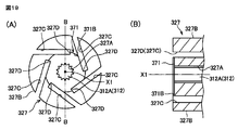
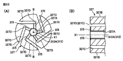
- the rotor is provided with a groove connecting at least one of the vane slit and the shaft hole or the other vane slit.
- the rotor since the rotor is provided with a groove connecting at least one of the vane slit and the shaft hole or another vane slit, negative pressure is likely to be generated in the vane slit as the vane pops out. When this happens, it is possible to suppress the generation of negative pressure by injecting fluid from the outside, and to easily eject the vane without increasing the number of parts.
- the groove may be provided on a side surface of the rotor. According to this configuration, the rotor can be easily provided by groove processing or the like.
- the groove may be an annular groove that connects the innermost portions of all the vane slits. According to this configuration, it is possible to suppress the generation of negative pressure due to the vane jumping out regardless of the position of the vane and without affecting the rotational balance of the rotor.
- a labyrinth passage may be provided on the side surface of the rotor between the vane slit and the shaft hole. According to this configuration, due to the labyrinth passage between the vane slit and the shaft hole, the wear powder generated on the vane side hardly flows to the center side of the rotor, and this wear powder flows to the center side of the rotor.
- the vane slit is offset to a position away from the shaft hole, and the groove connecting the vane slit and the shaft hole extends linearly along the radial direction of the rotation shaft of the rotor. It may be connected to the innermost part of the vane slit. According to this configuration, since the groove connecting the vane slit and the shaft hole extends linearly along the radial direction of the rotation axis of the rotor and is connected to the innermost part of the vane slit, the vane slit is separated from the shaft hole.
- the present invention includes a casing attached to a wall surface of a driving machine, a rotor that is driven to rotate inside the casing by a rotating shaft of the driving machine, and a retractable housing in the rotor.
- the casing includes a hollow cylinder chamber having an opening at an end thereof, and a side plate that closes the opening of the cylinder chamber.
- a communication hole is provided that allows a space formed between the side plate and the wall surface of the driving machine to communicate with another space having an atmospheric pressure or higher.
- the casing includes an expansion chamber formed in an exhaust path connecting the cylinder chamber and an exhaust port at a peripheral portion of the cylinder chamber, and the communication hole is formed in the expansion chamber. It is characterized by. Further, the present invention is characterized in that the communication hole is formed at a position higher than the rotation shaft in the expansion chamber. Further, the present invention is characterized in that the driving machine includes a bearing that pivotally supports the rotating shaft, and the communication hole is formed in the wall surface at a position higher than the bearing. In order to achieve the sixth object, the present invention provides a casing attached to a driving machine, a hollow cylinder chamber formed in the casing and having openings at both ends of the casing, and a rotating shaft of the driving machine.
- the vacuum pump includes a rotor that is movably provided in the axial direction and is driven to rotate in the cylinder chamber together with the rotating shaft, and a pair of side plates that close the opening of the cylinder chamber.
- the rotary shaft is provided with a push nut that restricts movement to the tip end side of the rotary shaft. According to this configuration, the push nut provided on the rotating shaft restricts the rotor from moving to the tip side of the rotating shaft, so that the contact between the rotor and the front side plate can be prevented with a simple configuration. As a result, the wear of the rotor and the side plate is suppressed, and the durability of the vacuum pump can be improved.
- the push nut is easily attached to the rotating shaft as compared with a fastening means such as a bolt, it is possible to easily prevent the rotor from moving to the tip side of the rotating shaft in a short time.
- the present invention inserts the rotor into the rotating shaft until it abuts on the side plate located on the drive machine side, and in this state, the push nut is moved until a predetermined reference value is exceeded. The push nut is pressed against the end face to lock the rotary nut on the rotating shaft.
- the rotor can be easily positioned with respect to the rotating shaft, and the assembly work of the pump can be performed in a short time without being an expert.
- the rotating shaft includes a locking portion in which a plurality of claw portions of the push nut are locked at a tip portion, and a reduced diameter portion having a diameter smaller than that of the locking portion.
- the diameter of the diameter portion is formed to be substantially the same as the inner diameter of the opening surrounded by the plurality of claw portions of the push nut. According to this configuration, since the diameter of the reduced diameter portion is formed to be substantially the same as the inner diameter of the opening surrounded by the plurality of claw portions of the push nut, the push nut can be moved along the reduced diameter portion. The push nut can be guided to the locking portion without being inclined with respect to the rotating shaft.
- the present invention is characterized in that a recess is formed in the front end surface of the rotor around a shaft hole into which the rotating shaft is inserted, and the push nut is locked to the rotating shaft in the recess. To do. According to this configuration, the push nut can be locked to the rotation shaft without protruding the tip end portion of the rotation shaft from the front end surface of the rotor, and the configuration of the vacuum pump can be simplified.
- the path length of the exhaust path can be formed longer accordingly. For this reason, when the compressed air discharged from the cylinder chamber flows through the exhaust path having a long path length, the compressed air collides with the wall surface of the exhaust path and is diffusely reflected, whereby the sound energy of the compressed air can be attenuated. Furthermore, since the compressed air attenuated in the exhaust path flows into the expansion chamber, and further expands and disperses in the expansion chamber and is further attenuated, noise and vibration during exhaust can be reduced. According to the present invention, since the casing is configured by press-fitting the cylinder portion into the casing body, the casing can be downsized.
- the casing body is made of a material having higher thermal conductivity than the rotary compression element, the heat generated when the rotary compression element is activated can be quickly transferred to the casing body, so that the casing body can sufficiently dissipate heat. can do.
- the expansion chamber is provided in the exhaust path, the compressed air flowing through the exhaust path expands and disperses in the expansion chamber and is attenuated by colliding with the partition wall of the expansion chamber and being attenuated. It is possible to reduce noise and vibration during the operation.
- the expansion chamber is provided at the peripheral edge portion of the cylinder chamber in the casing body, the cylinder chamber and the expansion chamber can be integrally formed in the casing body, thereby suppressing an increase in size of the compression device. Can do.
- the rotor is provided with a groove that connects at least one of the vane slit and the shaft hole or another vane slit, the vane can be easily ejected without increasing the number of parts.
- the space formed between the side plate and the wall surface of the driving machine is provided with the communication hole that communicates with another space that is equal to or higher than the atmospheric pressure, when this space is equal to or lower than the atmospheric pressure, When the air having a pressure equal to or higher than the atmospheric pressure flows into the space through the communication hole, the space is quickly restored to the atmospheric pressure (or higher than the atmospheric pressure). For this reason, since the situation in which the air in a drive machine flows into the said space is suppressed, the fall of the durability of a drive machine by the abrasion powder contained in this air can be prevented.
- the push nut provided on the rotating shaft restricts the rotor from moving to the tip side of the rotating shaft, so that the contact between the rotor and the front side plate can be prevented with a simple configuration.
- the wear of the rotor and the side plate is suppressed, and the durability of the vacuum pump can be improved.
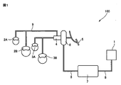
- FIG. 1 is a schematic view of a brake device using a vacuum pump according to this embodiment for achieving the first object.
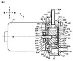
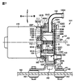
- FIG. 2 is a side sectional view of the vacuum pump.
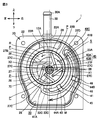
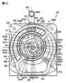
- FIG. 3 is a view of the vacuum pump as viewed from the front side.
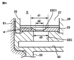
- 4 is a partially enlarged view of FIG. 2 showing exhaust holes formed in the cylinder liner.
- FIG. 5 is a table in which noise values corresponding to the respective configurations are described.
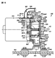
- FIG. 6 is a side partial sectional view of a vacuum pump according to another embodiment.
- FIG. 7 is a side partial sectional view of a vacuum pump according to this embodiment for achieving the second object.
- FIG. 8 is a view of the vacuum pump as viewed from the front side.
- FIG. 9 is a perspective view showing the back side of the casing body.
- FIG. 10A is a diagram showing a connection structure between the electric motor and the pump body, and B is a modification of the connection structure.
- FIG. 11 is a side partial sectional view of a vacuum pump according to this embodiment for achieving the third object.
- FIG. 12 is a view of the vacuum pump as viewed from the front side. 13 is a cross-sectional view taken along the line III-III in FIG.
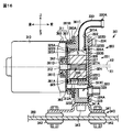
- FIG. 14 is a side partial sectional view of a vacuum pump according to another embodiment.
- FIG. 15 is a side partial sectional view of a vacuum pump according to another embodiment.
- FIG. 16 is a side partial cross-sectional view of the vacuum pump according to the first embodiment of the present invention for achieving the fourth object.
- FIG. 17 is a view of the vacuum pump as viewed from the front side.
- FIG. 18A is a view showing the side surface of the rotor together with the peripheral configuration
- FIG. 18B is a cross-sectional view taken along the line BB of FIG.
- FIG. 19A is a view showing a side surface of the rotor according to the second embodiment together with the peripheral configuration
- FIG. 20B is a cross-sectional view taken along line BB in FIG.
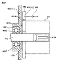
- FIG. 21 is an enlarged view of the output shaft of the electric motor together with the peripheral configuration.
- FIG. 22A is a view showing a side surface of the rotor according to the fourth embodiment together with the peripheral configuration
- FIG. 22B is a sectional view taken along line BB in FIG.
- FIG. 23 is a diagram for explaining a modification.
- FIG. 24 is a side partial sectional view of a vacuum pump according to this embodiment for achieving the fifth object.
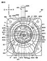
- FIG. 25 is a view of the vacuum pump as viewed from the front side.
- FIG. 26 is a rear view of the casing body.
- FIG. 27 is a drawing for explaining the flow of air.
- FIG. 28 is a schematic diagram of a brake device using a vacuum pump according to this embodiment for achieving the sixth object.
- FIG. 29 is a side sectional view of the vacuum pump.
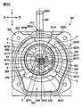
- FIG. 30 is a view of the vacuum pump as viewed from the front side.
- FIG. 31 is an exploded perspective view showing a connection structure between the rotor and the output shaft.
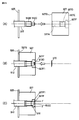
- FIG. 32 is a diagram showing the shapes of the tip portion of the rotating shaft and the push nut.
- FIG. 33 is a diagram illustrating a procedure for assembling the rotor.
- FIG. 1 is a schematic diagram of a brake device 100 that uses a vacuum pump 1 according to an embodiment of the present invention as a negative pressure source to achieve the first object.
- the brake device 100 includes, for example, front brakes 2A and 2B attached to left and right front wheels of a vehicle such as an automobile, and rear brakes 3A and 3B attached to left and right rear wheels.
- Each of these brakes is connected to each other by a master cylinder 4 and a brake pipe 9, and each brake is operated by a hydraulic pressure sent from the master cylinder 4 through the brake pipe 9.
- the brake device 100 includes a brake booster (brake booster) 6 connected to the brake pedal 5, and the vacuum tank 7 and the vacuum pump 1 are connected in series to the brake booster 6 through an air pipe 8. It is connected.
- the brake booster 6 uses the negative pressure in the vacuum tank 7 to boost the pedaling force of the brake pedal 5, and it is sufficient to move the piston (not shown) of the master cylinder 4 with a small pedaling force.
- the braking power can be pulled out.
- the vacuum pump 1 is disposed in the engine room of the vehicle, discharges the air in the vacuum tank 7 to the outside of the vehicle, and puts the vacuum tank 7 in a vacuum state.
- the use range of the vacuum pump 1 used for a motor vehicle etc. is -60kPa--80kPa, for example.
- FIG. 2 is a side partial sectional view of the vacuum pump 1
- FIG. 3 is a view of the vacuum pump 1 of FIG. 2 as viewed from the front side (right side in the figure).
- FIG. 3 illustrates a state in which members such as the pump cover 24 and the side plate 26 are removed in order to show the configuration of the cylinder chamber S.
- the directions indicated by the arrows at the top of FIGS. 2 and 3 respectively indicate the top, bottom, front, back, left and right of the vacuum pump 1.
- the front-rear direction is also referred to as the axial direction
- the left-right direction is also referred to as the width direction.
- FIG. 1 is also referred to as the axial direction
- the left-right direction is also referred to as the width direction.
- the vacuum pump 1 includes an electric motor (driving machine) 10 and a pump main body 20 that operates using the electric motor 10 as a driving source.
- the electric motor 10 and the pump main body 20 are integrated with each other. In a connected state, it is fixedly supported on a vehicle body such as an automobile.
- the electric motor 10 has an output shaft (rotary shaft) 12 that extends from the approximate center of one end (front end) of the case 11 formed in a substantially cylindrical shape toward the pump body 20 side (front side).
- the output shaft 12 functions as a drive shaft that drives the pump main body 20, and rotates with reference to a rotation center X1 extending in the front-rear direction.
- the front end portion 12A of the output shaft 12 is formed as a spline shaft, and engages with a spline groove 27D formed in a part of a shaft hole 27A penetrating in the axial direction of the rotor 27 of the pump body 20,
- the rotor 27 is connected to the rotor 27 so as to be integrally rotatable.
- the output shaft 12 rotates in the direction indicated by the arrow R (counterclockwise) in FIG. 3, thereby rotating the rotor 27 in the same direction around the rotation center X1 ( It is designed to rotate in the direction of arrow R).
- the case 11 includes a case main body 60 formed in a bottomed cylindrical shape and a cover body 61 that closes the opening of the case main body 60.
- the case main body 60 is formed by bending the peripheral edge portion 60A outward.
- the cover body 61 includes a disc portion (wall surface) 61A formed with substantially the same diameter as the opening of the case main body 60, and a cylindrical portion 61B that is connected to the periphery of the disc portion 61A and fits on the inner peripheral surface of the case main body 60.
- a bent portion 61C formed by bending the peripheral edge of the cylindrical portion 61B outward, the disc portion 61A and the cylindrical portion 61B enter the case body 60, and the bent portion 61C
- the case body 60 is fixed in contact with the peripheral edge 60A.
- one end part (front end) of the case 11 is recessed inward in the electric motor 10, and the fitting hole part 63 to which the pump main body 20 is attached by spigot fitting is formed.
- a through hole 61D through which the output shaft 12 passes and an annular bearing holding portion 61E extending inward of the case main body 60 are formed around the through hole 61D at the approximate center of the disc part 61A.
- the pump body 20 includes a casing body 22 fitted in a fitting hole 63 formed on the front side of the case 11 of the electric motor 10, and a cylinder chamber disposed in the casing body 22.
- the cylinder liner 23 which forms S, and the pump cover 24 which covers the said casing main body 22 from the front side are provided.
- a casing body 22, a cylinder liner 23, and a pump cover 24 are provided to constitute a casing 31 of the vacuum pump 1. As shown in FIG.
- the casing body 22 is made of, for example, a metal material having high thermal conductivity such as aluminum, and the shape seen from the front side is a substantially rectangular shape that is long in the vertical direction with the rotation center X1 as the center. Is formed.
- a communication hole 22A communicating with the cylinder chamber S provided in the casing main body 22 is formed in the upper portion of the casing main body 22, and a suction nipple 30 is press-fitted into the communication hole 22A.
- the suction nipple 30 is a straight pipe extending upward, and negative pressure air is supplied to one end 30A of the suction nipple 30 from an external device (for example, the vacuum tank 7 (see FIG. 1)).
- a tube or tube for feeding is connected.
- the casing body 22 is formed with a hole 22B with respect to the axial center X2 extending in the front-rear direction, and a cylinder liner 23 formed in a cylindrical shape is press-fitted into the hole 22B.
- the casing body 22 may be cast with the cylinder liner 23 cast.
- the shaft center X2 is parallel to the rotation center X1 of the output shaft 12 of the electric motor 10 described above and, as shown in FIG.
- the shaft center X2 is eccentric so that the outer peripheral surface 27B of the rotor 27 centered on the rotation center X1 is in contact with the inner peripheral surface 23A of the cylinder liner 23 formed with the shaft center X2 as a reference.
- the cylinder liner 23 is formed of the same metal material as the rotor 27 (in this embodiment, iron), and the inner peripheral surface 23A of the cylinder liner 23 is subjected to, for example, an electroless nickel plating process, The hardness of the inner peripheral surface 23A is increased.
- the cylinder liner 23 can be accommodated within the longitudinal range of the casing body 22 by press-fitting (or casting) the cylinder liner 23 into the hole 22 ⁇ / b> B formed in the casing body 22. Therefore, the cylinder liner 23 is prevented from protruding from the casing body 22, and the casing body 22 can be downsized. Further, the casing body 22 is formed of a material having higher thermal conductivity than the rotor 27. According to this, heat generated when the rotor 27 and the vane 28 are rotationally driven can be quickly transmitted to the casing body 22, so that the casing body 22 can sufficiently dissipate heat.
- the cylinder liner 23 is formed with an opening 23B that connects the communication hole 22A of the casing body 22 and the inside of the cylinder chamber S, and the air that has passed through the suction nipple 30 passes through the communication hole 22A and the opening 23B.
- exhaust holes 22 ⁇ / b> C and 23 ⁇ / b> C that pass through the casing body 22 and the cylinder liner 23 and discharge air compressed in the cylinder chamber S are provided at the lower part of the casing body 22 and the cylinder liner 23.
- the exhaust holes 23C provided in the cylinder liner 23 will be described later.
- Side plates 25 and 26 for closing the opening of the cylinder chamber S are disposed at the rear end and the front end of the cylinder liner 23, respectively.
- the side plates 25 and 26 are set to have a diameter larger than the inner diameter of the inner peripheral surface 23A of the cylinder liner 23, and are urged by the wave washers 25A and 26A, respectively, to the front end and the rear end of the cylinder liner 23, respectively. It is pressed. As a result, a sealed cylinder chamber S is formed inside the cylinder liner 23 except for the opening 23 ⁇ / b> B and the exhaust holes 23 ⁇ / b> C and 22 ⁇ / b> C connected to the suction nipple 30. In addition, it is good also as a structure which provides a seal ring instead of wave washer 25A, 26A.
- a rotor 27 is disposed in the cylinder chamber S.
- the rotor 27 has a columnar shape extending along the rotation center X1 of the electric motor 10, and has a shaft hole 27A through which the output shaft 12 that is a drive shaft of the pump body 20 is inserted, and radial direction from the shaft hole 27A.
- a plurality of guide grooves 27C are provided at equidistant intervals around the shaft hole 27A at intervals in the circumferential direction.
- a part of the shaft hole 27A is formed with a spline groove 27D that engages with a spline shaft provided at the distal end portion 12A of the output shaft 12, so that the rotor 27 and the output shaft 12 are spline-connected. Yes.
- a cylindrical recess 27F having a diameter larger than that of the shaft hole 27A is formed around the shaft hole 27A on the front end surface of the rotor 27, and the tip of the output shaft 12 extends into the recess 27F.
- a push nut 70 is attached to this, and the push nut 70 restricts the rotor 27 from moving toward the tip end side of the output shaft 12.
- the length of the rotor 27 in the front-rear direction is set to be approximately equal to the length of the cylinder chamber S of the cylinder liner 23, that is, the distance between the inner surfaces of the two side plates 25 and 26 facing each other. And the side plates 25 and 26 are substantially closed. Further, as shown in FIG.
- the outer diameter of the rotor 27 is such that the outer peripheral surface 27B of the rotor 27 maintains a minute clearance with the portion of the inner peripheral surface 23A of the cylinder liner 23 that is located obliquely downward to the right. Is set.
- the inside of the cylinder chamber S partitioned by the side plates 25 and 26 has a crescent shape between the outer peripheral surface 27B of the rotor 27 and the inner peripheral surface 23A of the cylinder liner 23, as shown in FIG. A space is constructed.
- the rotor 27 is provided with a plurality (five in this example) of vanes 28 that divide a crescent-shaped space.
- the vane 28 is formed in a plate shape, and its length in the front-rear direction is set to be approximately equal to the distance between the mutually facing inner surfaces of the two side plates 25, 26, similar to the rotor 27. ing. These vanes 28 are arranged so as to be able to protrude and retract from guide grooves 27 ⁇ / b> C provided in the rotor 27. Each vane 28 protrudes outward along the guide groove 27 ⁇ / b> C by centrifugal force as the rotor 27 rotates, and a tip of the vane 28 comes into contact with the inner peripheral surface 23 ⁇ / b> A of the cylinder liner 23.
- the crescent-shaped space described above is divided into five compression chambers P surrounded by the two adjacent vanes 28, 28, the outer peripheral surface 27B of the rotor 27, and the inner peripheral surface 23A of the cylinder liner 23. Partitioned. These compression chambers P rotate in the same direction as the rotation of the output shaft 12 in the direction of the arrow R of the rotor 27.
- the volume of the compression chamber P increases in the vicinity of the opening 23B, and decreases in the exhaust hole 23C. That is, the air sucked into one compression chamber P from the opening 23B by the rotation of the rotor 27 and the vane 28 is compressed while being rotated with the rotation of the rotor 27, and is discharged from the exhaust hole 23C.
- the rotary compression element is configured by including the rotor 27 and the plurality of vanes 28.
- the pump cover 24 is disposed on the front side plate 26 via a wave washer 26 ⁇ / b> A, and is fixed to the casing body 22 with bolts 66. As shown in FIG. 3, a seal groove 22D is formed on the front surface of the casing body 22 so as to surround a cylinder liner 23, an expansion chamber 33 and an exhaust path 40, which will be described later, and an annular seal material 67 ( FIG. 2) is arranged.
- the pump cover 24 is provided with an exhaust port 24 ⁇ / b> A at a position corresponding to the expansion chamber 33.
- This exhaust port 24A is for exhausting the air that has flowed into the expansion chamber 33 to the outside of the machine (outside the vacuum pump 1), and this exhaust port 24A prevents the backflow of air from the outside of the machine into the pump.
- a check valve 29 is attached.
- the vacuum pump 1 is configured by connecting the electric motor 10 and the pump main body 20, and the rotor 27 and the vane 28 connected to the output shaft 12 of the electric motor 10 include the cylinder liner of the pump main body 20. 23 slides in. For this reason, it is important to assemble the pump body 20 in accordance with the rotation center X1 of the output shaft 12 of the electric motor 10.
- the electric motor 10 has a fitting hole 63 formed around the rotation center X1 of the output shaft 12 on one end side of the case 11.
- a cylindrical fitting portion 22 ⁇ / b> F projecting rearward around the cylinder chamber S is integrally formed on the back surface of the casing body 22.
- the fitting portion 22 ⁇ / b> F is formed concentrically with the rotation center X ⁇ b> 1 of the output shaft 12 of the electric motor 10, and has an outer diameter that fits in the fitting hole portion 63 of the electric motor 10.
- the center position can be easily adjusted by simply fitting the fitting portion 22F of the casing body 22 into the fitting hole portion 63 of the electric motor 10, and the electric motor 10 and the pump body 20 can be aligned. Assembly work can be performed easily. Further, a seal groove 22E is formed around the fitting portion 22F on the back surface of the casing body 22, and an annular seal material 35 is disposed in the seal groove 22E.
- the casing main body 22 has an exhaust passage 40 communicating with the exhaust holes 23C and 22C of the cylinder chamber S and an expansion chamber for expanding compressed air introduced through the exhaust passage 40. 33 is formed.
- the cylinder liner 23 is formed in the casing body 22 such that the axis X2 of the cylinder liner 23 is eccentrically inclined leftward and upward with respect to the rotation center X1.
- the expansion chamber 33 is a space that expands and disperses the compressed air that has flowed in through the exhaust passage 40, and the compressed air that has flowed into the expansion chamber 33 expands and disperses and collides with the inner wall of the expansion chamber 33 to be diffusely reflected. Since the sound energy of the compressed air is attenuated, noise and vibration during exhaust can be reduced.
- the expansion chamber 33 is formed as a large closed space along the peripheral edge of the cylinder liner 23 from the lower side of the cylinder liner 23 to the upper side of the output shaft 12, and is formed in the pump cover 24. It communicates with the mouth 24A.
- the exhaust port 24A is provided so as to change the flow of exhaust air substantially perpendicularly to the air flow direction (arrow M direction) in the exhaust path 40 and the expansion chamber 33, and changes the direction of the air flow. Therefore, sound energy can be reduced.
- the exhaust path 40 is a space formed with a path cross-sectional area smaller than that of the expansion chamber 33, and the compressed air flowing into the exhaust path 40 is positively collided with the inner wall of the exhaust path 40 so as to attenuate sound energy.
- the casing body 22 includes a partition wall 41 provided outside the cylinder chamber S, and an exhaust path 40 is formed as a space partitioned by the partition wall 41.
- the partition wall 41 is formed in an arc shape substantially concentric with the cylinder chamber S, and one end 41A of the partition wall 41 is connected to the hole 22B at a position beyond the exhaust hole 22C.
- the other end 41 ⁇ / b> B of the partition wall 41 extends to a position where the space as the exhaust path 40 is not closed.
- the exhaust passage 40 is formed between the partition wall 41 and the cylinder chamber S, the inner passage 40A into which the compressed air from the exhaust hole 22C flows, and the expansion chamber formed outside the partition wall 41 described above.
- the inner path 40A and the outer path 40B are connected on the other end 41B side of the partition wall 41 to form a folded portion 40C.
- the compressed air discharged from the cylinder chamber S through the exhaust holes 22C and 23C flows through the inner path 40A and then reverses at the folded portion 40C and flows through the outer path 40B as shown by the arrow M, and enters the expansion chamber 33. Inflow.
- the exhaust path 40 since the exhaust path 40 includes the folded portion 40C formed by the partition wall 41, the path length of the exhaust path 40 can be formed long, and the compressed air flowing through the exhaust path 40 has a long path length.
- the sound energy of the compressed air can be attenuated by colliding with the wall surface of the exhaust path 40 and performing irregular reflection.
- the exhaust path 40 includes silencers 44A and 44B at the inlet of the inner path 40A and the outlet of the outer path 40B, respectively.
- silencing members 44A and 44B are porous members formed into a substantially rectangular shape by sintering metal particles such as copper and stainless steel, for example, and groove portions 45 and 46 provided on the side walls of the inner passage 40A and the outer passage 40B. It is inserted and fixed in each. According to this configuration, the compressed air flowing through the exhaust path 40 is rectified when passing through the minute spaces of the respective silencing members 44A and 44B, and the sound energy of the compressed air is absorbed by the silencing members. The sound energy of the compressed air flowing into the expansion chamber 33 from the path 40 can be attenuated, and noise and vibration during exhaust can be further reduced.
- FIG. 4 is a partially enlarged view of FIG. 2 showing the exhaust hole 23 ⁇ / b> C formed in the cylinder liner 23.
- the noise and vibration generated when exhausting are caused by pulsation of compressed air from the exhaust holes 23C and 22C of the cylinder chamber S as the rotor 27 and the vane 28 rotate.
- the applicant measured the noise value by changing the shape of the exhaust hole 23C variously. As shown in FIG.
- the exhaust hole 23C has a hole diameter d1 inside the cylinder chamber S. It has been found that noise is suppressed when formed in a tapered hole having a tapered surface 23C1 which is larger than the outer hole diameter d2 and is reduced from the hole diameter d1 to d2.
- the hole diameter d1 inside the cylinder chamber S of the exhaust hole 23C is set to be substantially the same as the hole diameter d3 of the exhaust hole 22C of the casing body 22 (10.5 mm in this embodiment).
- the outer hole diameter d2 is desirably about 70% of the above-described hole diameter d1, and in this embodiment, the diameter is set to 7 mm.
- the angle ⁇ of the tapered surface 23C1 is set to 120 °.
- the exhaust hole 23 ⁇ / b> C formed in the cylinder liner 23 is a tapered hole having a tapered surface 23 ⁇ / b> C ⁇ b> 1 that has an inner hole diameter d ⁇ b> 1 larger than the outer hole diameter d ⁇ b> 2 and decreases from the inner side toward the outer side.
- the exhaust amount from the cylinder chamber S can be reduced without extremely increasing the exhaust resistance from the exhaust hole 23C, so that the pulsation of the compressed air discharged from the cylinder chamber can be suppressed. Noise and vibration at the time of exhausting due to pulsation can be reduced.
- FIG. 5 shows a noise value corresponding to each configuration.
- the noise value a plurality of (for example, ten) measurement microphones are arranged around the vacuum pump 1, and the noise value when the vacuum pump 1 is operated in this state is measured for each microphone. Is an average value of.
- the noise value (63.4 dB) is 8.3 dB (about 12%) by providing the exhaust passage 40 with respect to the noise value (71.7 dB) of the configuration in which only the expansion chamber 33 is provided. Reduced. Further, by arranging the silencer members 44A and 44B in the exhaust path 40, the noise value (59.7 dB) is further reduced by 3.7 dB (about 6%), and a configuration in which the exhaust hole 23C is a tapered hole is added to this configuration.
- the noise value (58.6 dB) was further reduced by 1.1 dB (about 1.9%).
- the vacuum pump 1 with a reduced noise value can be realized by various means, and when the vacuum pump 1 is mounted on a vehicle, the discomfort caused by the noise of the vacuum pump 1 is suppressed. can do.
- the casing body 22 includes the cylinder chamber S in which the rotor 27 and the vane 28 slide, the expansion chamber 33 that expands the compressed air discharged from the cylinder chamber S, and the cylinder chamber S.
- the length of the exhaust path 40 can be increased by the amount folded by the folded portion 40C. it can. For this reason, when the compressed air discharged from the cylinder chamber S flows through the exhaust path 40 having a long path length, the compressed air collides with the wall surface of the exhaust path 40 and is diffusely reflected to attenuate sound energy of the compressed air. Can do. Furthermore, since the compressed air attenuated in the exhaust passage 40 flows into the expansion chamber 33 and further expands and disperses in the expansion chamber 33 and is further attenuated, noise and vibration during exhaust are reduced. be able to.
- the exhaust path 40 and the expansion chamber 33 are arranged in parallel to the peripheral edge portion of the cylinder chamber S in the casing body 22, and therefore the exhaust path 40, the expansion chamber 33, and the cylinder
- the chamber S can be formed integrally, and an increase in the size of the vacuum pump 1 can be suppressed.
- the sound deadening members 44A and 44B made of a porous material are disposed in the exhaust path 40, the compressed air flowing through the exhaust path 40 is rectified when passing through the sound deadening members 44A and 44B. At the same time, since the sound energy of the compressed air is absorbed by the silencer members 44A and 44B, noise and vibration during exhaust can be further reduced.
- the casing main body 22 and the cylinder liner 23 that forms the cylinder chamber S are provided.
- the cylinder liner 23 includes the exhaust hole 23 ⁇ / b> C connected to the exhaust path 40, and the exhaust hole 23 ⁇ / b> C is provided in the cylinder chamber S. Since the inner hole diameter d1 is larger than the outer hole diameter d2 and is formed in a tapered hole having a tapered surface 23C1 that decreases in diameter from the inside to the outside, the pulsation of the compressed air discharged from the cylinder chamber S is suppressed. It is possible to reduce the noise and vibration at the time of exhausting due to this pulsation. Next, another embodiment will be described. FIG.
- the vacuum pump 80 differs from the above-described embodiment in that it includes a pilot bearing that supports the tip of the output shaft 12 that rotates the rotor 27.
- symbol is attached
- the output shaft 12 is integrally provided with a bearing mounting portion 12A1 to which a pilot bearing 81 is mounted at the tip end portion 12A.
- the bearing mounting portion 12A1 is formed of the through hole 26B of the front side plate 26 and the pump cover 84. It extends through the bearing holding hole 84 ⁇ / b> A to the outside of the pump body 20.
- a bearing holding hole 84A is formed on the inner surface of the pump cover 84, and the pilot bearing 81 is held in the bearing holding hole 84A.
- the bearing holding hole 84A having a depth enough to hold the pilot bearing 81 is formed on the inner surface, the plate thickness of the pump cover 84 is formed thick. According to this configuration, since the tip end portion of the output shaft 12 is supported by the pilot bearing 81, the rotor 27 and the vane 28 are stably rotated in the cylinder chamber S by suppressing the shake of the output shaft 12. Can be made. Therefore, it is possible to reduce the operating noise of the rotor 27 and the vane 28.
- the exhaust path 40 is configured to include one folded portion 40C, but two or more folded portions may be provided as long as it can be installed.
- the configuration has been described in which the two silencing members 44A and 44B are arranged in the exhaust path 40, but the number of the silencing members may be one or three or more.
- the sintered metal thing which sintered the metal particle was illustrated as a silencing member, if the temperature conditions are prepared, the silencing member formed with sintered resin can also be arrange
- FIG. 7 is a side partial sectional view of the vacuum pump 1 according to the embodiment of the present invention for achieving the second object.
- FIG. 8 is a view of the vacuum pump 101 of FIG. 7 as viewed from the front side (right side in the figure). However, FIG. 8 illustrates a state in which members such as the pump cover 124 and the side plate 126 are removed to show the configuration of the cylinder chamber S. Moreover, in FIG. 8, the state which removed the attachment member 140 is shown.
- the front-rear direction is also referred to as the axial direction
- the left-right direction is also referred to as the width direction.
- the vacuum pump 101 is a rotary vane type vacuum pump, and is used as a negative pressure source of a brake booster (not shown) such as an automobile.
- the vacuum pump 101 is usually disposed in the engine room and connected to the brake booster via a vacuum tank (not shown).
- the use range of the vacuum pump 101 used for a motor vehicle etc. is -60kPa--80kPa, for example.
- the vacuum pump 101 includes an electric motor 110 and a pump main body 120 disposed on the electric motor 110. With the electric motor 110 and the pump main body 120 connected together, The mounting member 140 is fixedly supported on a vehicle body 150 such as an automobile.
- the mounting member 140 includes a mounting plate 141 provided with a rectangular protruding groove 141A extending in the width direction of the pump main body 120, and anti-vibration rubbers 142 and 142 fixed to the front end and the rear end of the mounting plate 141, respectively. These anti-vibration rubbers 142, 142 are fitted and held in holes formed in the vehicle body.
- the mounting plate 141 is fixed to the lower surface of the pump main body 120 with a bolt 143 by a protruding groove 41A.
- the electric motor 110 has an output shaft 112 extending from the approximate center of one end (front end) of the case 111 formed in a substantially cylindrical shape toward the pump main body 120 side (front side).
- the output shaft 112 rotates with reference to a rotation center X1 extending in the front-rear direction.
- a spline portion 112 ⁇ / b> B that fits into a rotor 127, which will be described later, of the pump main body 120 and serves as a detent for the rotor 127 is formed at the tip portion 112 ⁇ / b> A of the output shaft 112.
- a key may be provided on the outer surface of the output shaft 112 to prevent the rotor 127 from spinning freely.
- the output shaft 112 rotates in the direction of arrow R (counterclockwise) in FIG.
- the case 111 includes a case main body 160 formed in a bottomed cylindrical shape and a cover body 161 that closes the opening of the case main body 160.
- the case main body 160 is formed by bending the peripheral edge portion 160A outward. Yes.
- the cover body 161 includes a disc portion 161A formed with substantially the same diameter as the opening of the case main body 160, a cylindrical portion 161B that is connected to the periphery of the disc portion 161A and fits on the inner peripheral surface of the case main body 160, and
- the cylindrical portion 161B is integrally formed with a bent portion 161C formed by bending the peripheral edge outward, and the disc portion 161A and the cylindrical portion 161B enter the case main body 160, and the bent portion 161C is inserted into the case main body 160. It is abutting and fixed to the peripheral portion 160A.
- one end (front end) of the case 111 is recessed inward in the electric motor 110, and a fitting hole 63 into which the pump main body 120 is fitted in is formed.
- the pump main body 120 includes a casing main body 122 that is fitted into a fitting hole 163 formed on the front side of the case 111 of the electric motor 110, and a cylinder chamber that is press-fitted into the casing main body 122.
- the cylinder part 123 which forms S, and the pump cover 124 which covers the said casing main body 122 from the front side are provided.
- the casing 131 of the vacuum pump 101 is configured by including the casing body 122, the cylinder portion 123, and the pump cover 124.
- the casing main body 122 is made of a metal material having high thermal conductivity such as aluminum, and the shape viewed from the front side is a substantially rectangular shape that is long in the vertical direction with the rotation center X1 as the center. Is formed.
- a communication hole 122A communicating with the cylinder chamber S provided in the casing main body 122 is formed in the upper portion of the casing main body 122, and a vacuum suction nipple (suction pipe) 130 is press-fitted into the communication hole 122A. As shown in FIG.
- the vacuum suction nipple 130 is a pipe bent in a substantially L shape.
- One end 130A of the vacuum suction nipple 130 is connected to an external device (for example, a vacuum tank (not shown)).
- a tube or tube for supplying negative pressure air is connected.
- this external device since the vacuum suction nipple 130 is press-fitted into the communication hole 122A of the casing body 122, this external device is arranged when the position where the external device is arranged in advance is known as in a vehicle. It is only necessary to press-fit with the one end 130A facing in the direction in which the pipe or tube for supplying negative pressure air can be freely set with a simple configuration.
- the casing body 122 is formed with a hole 122B with reference to the axial center X2 extending in the front-rear direction, and a cylindrical cylinder 23 is press-fitted into the hole 122B.
- the shaft center X2 is parallel to the rotation center X1 of the output shaft 112 of the electric motor 110 described above, and is eccentric leftward and obliquely upward with respect to the rotation center X1 as shown in FIG. In this configuration, the shaft center X2 is decentered so that an outer peripheral surface 127B of a rotor 127, which will be described later, centered on the rotation center X1 is in contact with an inner peripheral surface 123A of the cylinder portion 123 formed with the shaft center X2 as a reference. Yes.
- the cylinder part 123 is made of the same metal material as the rotor 127 (in this embodiment, iron). In this configuration, the cylinder portion 123 and the rotor 127 have the same thermal expansion coefficient. Therefore, the outer peripheral surface 127B of the rotor 127 and the cylinder portion 23 when the rotor 127 rotates are irrespective of temperature changes of the cylinder portion 123 and the rotor 127. It is possible to prevent contact with the inner peripheral surface 123A. Further, since the cylinder portion 123 and the rotor 127 have the same thermal expansion coefficient, the clearance between the side surface of the rotor 127 and side plates 125 and 126 (described later) disposed at the rear end and the front end of the cylinder portion 123 is stabilized.
- the cylinder portion 123 can be accommodated within the longitudinal range of the casing body 122 by press-fitting the cylinder portion 23 into the hole portion 122B formed in the casing body 122. Projection from the casing body 122 is prevented, and the casing body 122 can be downsized. Further, the casing body 122 is formed of a material having higher thermal conductivity than the rotor 127. According to this, the heat generated when the rotor 127 and the vane 128 are rotationally driven can be quickly transmitted to the casing body 122, so that the casing body 122 can sufficiently dissipate heat.
- the cylinder portion 123 is formed with an opening (communication hole) 123B connected to the communication hole 122A of the casing body 122, and the other end (tip) 130B of the vacuum suction nipple 130 is formed in the opening 123B.
- the other end 130B of the vacuum suction nipple 130 is engaged with the opening 123B of the cylinder part 123. Prevention can be realized.
- Discharge holes 122 ⁇ / b> C and 123 ⁇ / b> C through which the air compressed in the cylinder chamber S is discharged are provided below the casing main body 122 and the cylinder portion 123.
- Side plates 125 and 126 are disposed at the rear end and the front end of the cylinder portion 123, respectively.
- the side plates 125 and 126 are set to have a diameter larger than the inner diameter of the inner peripheral surface 123A of the cylinder portion 23, and are urged by the gaskets 125A and 126A to be pressed against the front end and the rear end of the cylinder portion 123, respectively. It has been.
- a sealed cylinder chamber S is formed inside the cylinder portion 123 except for the opening 123B and the discharge ports 123C and 122C connected to the vacuum suction nipple 130.
- a rotor 127 is disposed in the cylinder chamber S inside the cylinder portion 123.
- the rotor 127 is formed in a thick cylindrical shape, and the output shaft 112 on which the above-described spline portion 112B is formed is fitted to the inner peripheral surface 127A. With this spline fitting configuration, the rotor 127 rotates integrally with the output shaft 12.
- the length of the rotor 127 in the front-rear direction is set to be approximately equal to the length of the cylinder portion 123, that is, the distance between the mutually facing inner surfaces of the two side plates 125 and 126.
- the outer diameter of the rotor 127 is such that the outer peripheral surface 27B of the rotor 127 maintains a minute clearance with the portion of the inner peripheral surface 123A of the cylinder portion 123 that is located obliquely downward to the right. Is set.
- a crescent-shaped space is formed between the outer peripheral surface 127 ⁇ / b> B of the rotor 127 and the inner peripheral surface 123 ⁇ / b> A of the cylinder portion 123.
- the rotor 127 is provided with a plurality of (five in this example) vanes 128 that divide a crescent-shaped space.
- the vane 128 is formed in a plate shape, and its length in the front-rear direction is set to be substantially equal to the distance between the mutually facing inner surfaces of the two side plates 125 and 126, as in the rotor 127. ing. These vanes 128 are disposed so as to freely enter and exit from guide grooves 127 ⁇ / b> C provided in the rotor 127.
- each vane 128 protrudes outward along the guide groove 127 ⁇ / b> C by centrifugal force, and a tip thereof is brought into contact with the inner peripheral surface 123 ⁇ / b> A of the cylinder portion 123.
- the crescent-shaped space described above is divided into five compression chambers P surrounded by the two vanes 128, 128 adjacent to each other, the outer peripheral surface 127B of the rotor 127, and the inner peripheral surface 123A of the cylinder portion 123. Partitioned.
- the rotary compression element is configured by including the rotor 127 and the plurality of vanes 128. In this configuration, as shown in FIG.
- the cylinder portion 123 is formed in the casing body 122 such that the axis X ⁇ b> 2 of the cylinder portion 123 is eccentrically inclined leftward and upward with respect to the rotation center X ⁇ b> 1.
- the casing body 122 is formed with an expansion chamber 133 communicating with the discharge ports 123C and 122C in the direction opposite to the direction in which the cylinder portion 123 is eccentric.
- the expansion chamber 133 is formed in a crescent shape along the outer peripheral surface of the cylinder portion 123, and portions near the discharge ports 123 ⁇ / b> C and 122 ⁇ / b> C further bulge downward, and an exhaust port 124 ⁇ / b> A formed in the pump cover 124.
- the expansion chamber 133 communicating with the discharge ports 123C and 122C is formed in the casing body 122. Can do. For this reason, it is not necessary to provide the expansion chamber 133 outside the casing main body 122, the casing main body 122 can be downsized, and the vacuum pump 101 can be downsized. Further, the air discharged from the discharge ports 123C and 122 is introduced into the expansion chamber 133 and expanded, thereby reducing noise.
- the pump cover 124 is disposed on the front side plate 126 via a gasket 126 ⁇ / b> A, and is fixed to the casing body 122 with bolts 134.
- a seal groove 122D is formed on the front surface of the casing body 122 so as to surround the cylinder portion 123 and the expansion chamber 133, and an annular seal material 135 is disposed in the seal groove 122D.
- the pump cover 124 is provided with an exhaust port 124 ⁇ / b> A at a position corresponding to the expansion chamber 133.
- This exhaust port 124A is for exhausting the air that has flowed into the expansion chamber 133 to the outside of the machine (outside of the vacuum pump 101), and this exhaust port 124A prevents the backflow of air from the outside of the machine into the pump.
- a check valve 129 is attached.
- FIG. 9 is a perspective view of the casing body 122 as seen from the back.
- the vacuum pump 101 is configured by connecting the electric motor 110 and the pump main body 120, and the rotor 127 and the vane 128 connected to the output shaft 12 of the electric motor 110 are the cylinder portion of the pump main body 120. Slide in 123. For this reason, it is important to assemble the pump body 120 in accordance with the rotation center X1 of the output shaft 112 of the electric motor 110. For this reason, in the present embodiment, as described above, the electric motor 110 has the fitting hole 163 formed around the rotation center X ⁇ b> 1 of the output shaft 112 on one end side of the case 111. On the other hand, as shown in FIG.
- a cylindrical fitting portion 122 ⁇ / b> F that protrudes rearward around the cylinder chamber S is integrally formed on the back surface of the casing body 122.
- the fitting portion 122 ⁇ / b> F is formed concentrically with the rotation center X ⁇ b> 1 of the output shaft 112 of the electric motor 110, and has an outer diameter that fits in the fitting hole 163 of the electric motor 110. For this reason, in this configuration, the center position can be easily adjusted by simply fitting the fitting portion 122F of the casing body 122 into the fitting hole 163 of the electric motor 110. Can be easily assembled.
- a seal groove 122E is formed around the fitting portion 122F on the back surface of the casing body 122, and an annular seal material 136 is disposed in the seal groove 122E.
- the casing main body 122 and the case 111 of the electric motor 110 are combined with the bolts 134 for fixing the pump cover 124.
- a female screw portion 160A1 is provided on the peripheral edge portion 160A of the case main body 160, and the bolt cover 134 is screwed into the female screw portion 160A1, whereby the pump cover 124, The casing body 122 and the case 111 of the electric motor 110 are fixed together.
- the pump cover 124, the casing main body 122, and the case 111 of the electric motor 110 can be firmly fixed by forming the female screw portion 160A1 thicker than the plate thickness of the peripheral edge portion 160A.
- the female screw portion 160A1 may be formed so as to protrude toward the casing body 122, and the female screw portion 160A1 may be accommodated in the hole 160C1 formed in the bent portion 161C of the cover body 161. . According to this configuration, the female thread portion 160A1 is not projected and exposed on the surface of the vacuum pump 1, and the design can be improved.
- the casing is formed of a material having higher thermal conductivity than the rotor 27 and the vane 128. Since the casing main body 122 and the cylinder portion 123 that is press-fitted into the casing main body 122 and the rotor 127 and the vane 128 slide are provided, the cylinder portion 123 is press-fitted into the casing main body 122 to constitute the casing 131.
- the casing 131 can be downsized.
- the casing main body 122 is also formed of a material having high heat conductivity for the rotor 127 and the vane 128, the heat generated when the rotor 127 and the vane 128 are driven can be quickly transmitted to the casing main body 122, so that the casing Heat can be sufficiently radiated from the main body 122.
- the casing main body 122 and the cylinder portion 123 include the communication hole 122A and the opening 123B that penetrate the casing main body 122 and the cylinder portion 123 and communicate with the cylinder portion 123, respectively.
- the cylinder portion 123 is When iron having a low thermal expansion coefficient is used, even if the press-fitting allowance of the cylinder portion 123 is reduced due to thermal expansion, the other end 130B of the vacuum suction nipple 130 is engaged with the opening 123B of the cylinder portion 123. It is possible to prevent the portion 123 from rotating and coming off.
- the cylinder portion 123 is formed of a material having a thermal expansion coefficient substantially equal to that of the rotor 127. Therefore, the clearance between the side surface of the rotor 127 and the side plates 125 and 126 due to temperature changes. And the contact between the inner peripheral surface 123A of the cylinder portion 23 and the outer peripheral surface 127 of the rotor 127 can be prevented. Further, according to the present embodiment, the cylinder body 123 is disposed in the casing body 122 at a position eccentric from the rotation center X1 of the rotor 127, and the cylinder section 123 is disposed at the peripheral portion on the rotation center X1 side of the cylinder portion 123.
- the expansion chamber 133 communicated with the expansion chamber 133 is formed, it is not necessary to provide the expansion chamber 133 outside the casing main body 122, so that the casing main body 122 can be downsized, and the vacuum pump 101 can be downsized. Can do.
- the present invention is not limited to the above-described embodiment, and various modifications and changes can be made based on the technical idea of the present invention. It is.
- a vane type vacuum pump is used as the vacuum pump 1
- a scroll type may be used as long as it includes a rotary compression element.
- FIG. 11 is a side partial sectional view of a vacuum pump (compression device) 201 according to an embodiment of the present invention for achieving the third object.
- FIG. 12 is a view of the vacuum pump 201 of FIG. 11 as viewed from the front side (the right side in the figure). However, FIG. 12 illustrates a state in which members such as the pump cover 224 and the side plate 226 are removed in order to show the configuration of the cylinder chamber S. Moreover, in FIG. 12, the state which removed the attachment member 240 is shown.
- the front-rear direction is also referred to as the axial direction
- the left-right direction is also referred to as the width direction.
- a vacuum pump 201 shown in FIG. 11 is a rotary vane type vacuum pump, and is used as a negative pressure source of a brake booster (not shown) such as an automobile.
- the vacuum pump 201 is usually disposed in the engine room and connected to the brake booster via a vacuum tank (not shown).
- the range of use of the vacuum pump 201 used in an automobile or the like is, for example, ⁇ 60 kPa to ⁇ 80 kPa.
- the vacuum pump 201 includes an electric motor 210 and a pump main body 220 disposed on the electric motor 210. With the electric motor 210 and the pump main body 220 being integrally connected, The mounting member 240 is fixedly supported on the vehicle body 250 such as an automobile.
- the mounting member 240 includes a mounting plate 241 provided with a rectangular protruding groove 241A extending in the width direction of the pump main body 220, and vibration-proof rubbers 242 and 242 fixed to the front end and the rear end of the mounting plate 241, respectively. These anti-vibration rubbers 242 and 242 are fitted and held in holes formed in the vehicle body.
- the mounting plate 241 is fixed to the lower surface of the pump main body 220 with a bolt 243 by a protruding groove 241A.
- the electric motor 210 has an output shaft 212 extending from the approximate center of one end (front end) of the case 211 formed in a substantially cylindrical shape toward the pump main body 220 side (front side).
- the output shaft 212 rotates with reference to a rotation center X1 extending in the front-rear direction.
- a spline portion 212 ⁇ / b> B is formed at the tip end portion 212 ⁇ / b> A of the output shaft 212 so as to be fitted to a rotor 227, which will be described later, of the pump main body 220 and to prevent the rotor 227 from rotating. It is also possible to provide a key on the outer surface of the output shaft 212 to prevent the rotor 227 from spinning idle.
- the electric motor 210 when the power source (not shown) is turned on, the output shaft 212 rotates in the direction of arrow R (counterclockwise) in FIG.
- the case 211 includes a case main body 260 formed in a bottomed cylindrical shape and a cover body 261 that closes an opening of the case main body 260.
- the case main body 260 is formed by bending a peripheral edge portion 260A outward. Yes.
- the cover body 261 includes a disc portion 261A formed to have substantially the same diameter as the opening of the case body 260, a cylindrical portion 261B that is connected to the periphery of the disc portion 261A and fits on the inner peripheral surface of the case body 260, and
- the cylindrical portion 261B is integrally formed with a bent portion 261C formed by bending the outer periphery outward, the disk portion 261A and the cylindrical portion 261B enter the case main body 260, and the bent portion 261C is the case main body 260. Is fixed in contact with the peripheral portion 260A.
- the pump body 220 includes a casing body 222 that is fitted into a fitting hole 263 formed on the front side of the case 211 of the electric motor 210, and a cylinder chamber that is press-fitted into the casing body 222.
- the cylinder part 223 which forms S, and the pump cover 224 which covers the said casing main body 222 from the front side are provided.
- the casing 231 of the vacuum pump 201 is configured by including the casing body 222, the cylinder part 223, and the pump cover 224.
- the casing main body 222 is made of a metal material having high thermal conductivity such as aluminum, and the shape seen from the front side is a substantially rectangular shape that is long in the vertical direction with the rotation center X1 as the center. Is formed.
- a communication hole 222A communicating with the cylinder chamber S provided in the casing main body 222 is formed at the upper portion of the casing main body 222, and a vacuum suction nipple 230 is press-fitted into the communication hole 222A.
- the vacuum suction nipple 230 is a pipe bent in a substantially L shape.
- One end 230A of the vacuum suction nipple 230 is connected to an external device (for example, a vacuum tank (not shown)).
- a tube or tube for supplying negative pressure air is connected.
- the vacuum suction nipple 230 is press-fitted into the communication hole 222A of the casing body 222, this external device is arranged when the position where the external device is arranged in advance is known as in a vehicle. It is only necessary to press-fit the end 230A in the direction in which the pipe or tube for supplying negative-pressure air can be freely set with a simple configuration.
- the casing main body 222 is formed with a hole 222B with reference to the axial center X2 extending in the front-rear direction, and a cylindrical cylinder 223 is press-fitted into the hole 222B.
- the shaft center X2 is parallel to the rotation center X1 of the output shaft 212 of the electric motor 210 described above, and is eccentrically leftward and upward with respect to the rotation center X1 as shown in FIG. In this configuration, the shaft center X2 is eccentric so that an outer peripheral surface 227B of a rotor 227, which will be described later, centering on the rotation center X1 is in contact with an inner peripheral surface 223A of the cylinder portion 223 formed with the shaft center X2 as a reference. Yes.
- the cylinder portion 223 is formed of the same metal material as the rotor 227 (in this embodiment, iron).
- the cylinder portion 223 and the rotor 227 have the same thermal expansion coefficient, so that the outer peripheral surface 227B of the rotor 227 and the cylinder portion 223 when the rotor 227 rotates are independent of the temperature changes of the cylinder portion 223 and the rotor 227.
- the contact with the inner peripheral surface 223A can be prevented.
- the cylinder portion 223 can be accommodated within the longitudinal range of the casing body 222 by press-fitting the cylinder portion 223 into the hole 222B formed in the casing body 222, the cylinder portion 223 Projection from the casing body 222 is prevented, and the casing body 222 can be downsized.
- the casing body 222 is made of a material having higher thermal conductivity than the rotor 227. According to this, the heat generated when the rotor 227 and the vane 228 are rotationally driven can be quickly transmitted to the casing body 222, so that the casing body 222 can sufficiently dissipate heat.
- the cylinder portion 223 is formed with an opening 223B that connects the communication hole 222A of the casing body 222 and the inside of the cylinder chamber S, and the air that has passed through the vacuum suction nipple 230 passes through the communication hole 222A and the opening 223B. Supplied in.
- the suction path 232 is formed by including the vacuum suction nipple 230, the communication hole 222A of the casing body 222, and the opening 223B of the cylinder part 223.
- Discharge ports 222 ⁇ / b> C and 223 ⁇ / b> C that pass through the casing body 222 and the cylinder part 223 and discharge air compressed in the cylinder chamber S are provided below the casing body 222 and the cylinder part 223.
- Side plates 225 and 226 are disposed at the rear end and the front end of the cylinder part 223, respectively.
- the diameters of these side plates 225 and 226 are set to be larger than the inner diameter of the inner peripheral surface 223A of the cylinder part 223, and are urged by the gaskets 225A and 226A to press against the front end and the rear end of the cylinder part 223, respectively. It has been. Thereby, a sealed cylinder chamber S is formed inside the cylinder portion 223 except for the opening 223 ⁇ / b> B and the discharge ports 223 ⁇ / b> C and 222 ⁇ / b> C connected to the vacuum suction nipple 230.
- a rotor 227 is disposed in the cylinder chamber S inside the cylinder portion 223.
- the rotor 227 is formed in a thick cylindrical shape, and the output shaft 212 on which the above-described spline portion 212B is formed is fitted to the inner peripheral surface 227A. With this spline fitting configuration, the rotor 227 rotates integrally with the output shaft 212.
- the length of the rotor 227 in the front-rear direction is set to be approximately equal to the length of the cylinder portion 223, that is, the distance between the mutually facing inner surfaces of the two side plates 225 and 226. Further, as shown in FIG.
- the outer diameter of the rotor 227 is such that the outer peripheral surface 227B of the rotor 227 maintains a minute clearance with the portion of the inner peripheral surface 223A of the cylinder portion 223 located obliquely below the right. Is set. Thereby, as shown in FIG. 12, a crescent-shaped space is formed between the outer peripheral surface 227B of the rotor 227 and the inner peripheral surface 223A of the cylinder portion 223.
- the rotor 227 is provided with a plurality of (five in this example) vanes 228 that divide a crescent-shaped space.
- the vane 228 is formed in a plate shape, and its length in the front-rear direction is set to be approximately equal to the distance between the mutually facing inner surfaces of the two side plates 225 and 226, as in the rotor 227. ing. These vanes 228 are disposed so as to freely enter and exit from guide grooves 227 ⁇ / b> C provided in the rotor 227. As the rotor 227 rotates, each vane 228 protrudes outward along the guide groove 227C by centrifugal force, and a tip of the vane 228 is brought into contact with the inner peripheral surface 223A of the cylinder portion 223.
- the crescent-shaped space described above is divided into five compression chambers P surrounded by the two vanes 228 and 228 adjacent to each other, the outer peripheral surface 227B of the rotor 227, and the inner peripheral surface 223A of the cylinder portion 223. Partitioned. These compression chambers P rotate in the same direction with the rotation of the rotor 227 in the direction of arrow R accompanying the rotation of the output shaft 212, and the volume of the compression chamber P increases near the opening 223B, while it decreases at the discharge port 223C.
- the air sucked into one compression chamber P from the opening 223B by the rotation of the rotor 227 and the vane 228 is compressed while being rotated along with the rotation of the rotor 227, and is discharged from the discharge port 223C.
- the rotary compression element is configured by including the rotor 227 and the plurality of vanes 228.
- the cylinder portion 223 is formed in the casing body 222 such that the axial center X2 of the cylinder portion 223 is eccentrically inclined leftward and upward with respect to the rotation center X1.
- a resonance chamber 234 aligned with the expansion chamber 233 is formed at the peripheral edge of each.
- the expansion chamber 233 and the resonance chamber 234 are partitioned by a rib 235 formed integrally with the casing main body 222. As shown in FIG. 13, the expansion chamber 233 and the resonance chamber (resonator) 234 are connected to the rib 235.
- An orifice 235A is formed.
- the expansion chamber 233 is formed as a large closed space below the cylinder portion 223 and communicates with an exhaust port 224 ⁇ / b> A formed in the pump cover 224.
- the compressed air that has flowed into the expansion chamber 233 expands and disperses in the expansion chamber 233, collides with the partition walls of the expansion chamber 233, and is irregularly reflected. Thereby, since the sound energy of compressed air is attenuated, noise and vibration during exhaust can be reduced.
- the exhaust passage 237 is configured by including discharge ports 222C and 223C, an expansion chamber 233, and an exhaust port 224A formed in the casing body 222 and the cylinder part, respectively.
- the expansion chamber 233 is connected to a Helmholtz resonance chamber 234 branched from the exhaust path 237.
- the resonance chamber 234 is formed so as to generate a resonance that cancels out the pressure pulsation of the compressed air flowing through the exhaust passage 237, and suppresses noise and vibration due to the pressure pulsation.
- the resonance chamber 234 is designed to generate a resonance frequency that matches the fundamental frequency of the above-described air pressure pulsation.
- the resonance frequency is an orifice 235 A for connecting to the expansion chamber 233.
- the pressure pulsation of the air discharged by the rotation of the rotor 227 and the vane 228 can be reduced, and noise and vibration during exhaust can be further reduced. Furthermore, in the present embodiment, by arranging the cylinder part 223 eccentric from the rotation center X1 of the rotor 227, a large space can be secured in the peripheral part of the cylinder part 223 on the rotation center X1 side in the casing body 222. it can. For this reason, by arranging the expansion chamber 233 and the resonance chamber 234 in this space in parallel, the expansion chamber 233 and the resonance chamber 234 can be integrally formed in the casing main body 222. Therefore, the expansion chamber 233 and the resonance chamber 234 can be integrally formed.
- the casing main body 222 can be downsized, and the vacuum pump 201 can be downsized. Further, the casing body 222 has an intake side expansion chamber 238 formed at the peripheral edge portion of the cylinder portion 223 on the side where the cylinder portion 223 is eccentric.
- the intake side expansion chamber 238 is provided in the intake path 232 that connects the vacuum suction nipple 230 and the cylinder chamber S described above.
- the ribs 236 and 239 provided integrally with the casing body 222 They are divided into an expansion chamber 233 and a resonance chamber 234, respectively.
- the air flowing through the intake passage 232 expands and disperses in the intake side expansion chamber 238 and is attenuated by colliding with the partition wall of the intake side expansion chamber 238 and being attenuated.
- the noise and vibration during intake can be reduced.
- a desiccant 265 such as silica gel or zeolite is disposed in the intake side expansion chamber 238, for example.
- the desiccant 265 is formed by fixing silica gel or zeolite particles so as not to pass through the discharge ports 223C and 222C, and removes moisture in the air that has flowed into the intake side expansion chamber 238.
- the vacuum suction nipple 230 can be provided at an arbitrary location as long as the intake side expansion chamber 238 extends, and the vacuum suction nipple 230 can be provided in accordance with the position where the vacuum pump 201 is installed in the vehicle.
- the mounting position can be changed.
- the casing main body 222 is formed with the expansion chamber 233, the resonance chamber 234, and the intake side expansion chamber 238 at the peripheral edge of the cylinder portion 223. Therefore, the expansion chamber 233, the resonance chamber 234, and the intake side The expansion chamber 238 can be arranged in the casing body 222 in a well-organized manner.
- the casing main body 222 can be downsized, and the vacuum pump 201 can be downsized.
- the expansion chamber 233, the resonance chamber 234, and the intake side expansion chamber 238 are disposed on the peripheral edge of the cylinder portion 223, and the expansion chamber 233, the resonance chamber 234, and the intake side expansion chamber 238 are respectively connected to the ribs 235.
- the pump cover 224 is disposed on the front side plate 226 via a gasket 226 ⁇ / b> A, and is fixed to the casing body 222 with bolts 266. As shown in FIG. 12, a seal groove 222D is formed on the front surface of the casing body 222 so as to surround the cylinder portion 223 and the expansion chamber 233, and an annular seal member 267 is disposed in the seal groove 222D.
- the pump cover 224 has an exhaust port 224 ⁇ / b> A at a position corresponding to the expansion chamber 233.
- This exhaust port 224A is for exhausting the air that has flowed into the expansion chamber 233 to the outside of the machine (outside of the vacuum pump 201), and this exhaust port 224A prevents the backflow of air from the outside of the machine into the pump.
- a check valve 229 is attached.
- the casing 231 is configured such that the casing 222 in which the cylinder chamber S in which the rotor 227 and the vane 228 slide is formed, and the cylinder chamber S and the exhaust port 224A are connected to each other.
- the passage 237 and the expansion chamber 233 formed in the exhaust passage 237 are provided, and the expansion chamber 233 is provided in the peripheral portion of the cylinder chamber S in the casing body 222, the compressed air flowing through the exhaust passage 237 is expanded into the expansion chamber 233.
- the noise and vibration when exhausted from the exhaust port 224A to the outside of the machine can be reduced by being attenuated by expanding and dispersing in the interior and colliding with the partition wall of the expansion chamber 233 and being diffusely reflected.
- the expansion chamber 233 is provided at the peripheral edge of the cylinder chamber S in the casing body 222, the cylinder chamber S and the expansion chamber 233 can be integrally formed in the casing body 222, and the vacuum pump 201 Increase in size can be suppressed.
- the Helmholtz resonance chamber 234 branched from the exhaust path 237 is connected to the expansion chamber 233 via the orifice 235A, the sound energy of the air expanded in the expansion chamber 233 is obtained. Is oscillated and attenuated by the air spring in the orifice 235A and the resonance chamber 234, the pressure pulsation of the air discharged from the cylinder chamber S can be reduced, and noise and vibration during exhausting can be further reduced. be able to.
- the cylinder chamber S is provided at a position eccentric from the rotation center X1 of the rotor 227 and the vane 228 in the casing main body 222.
- the casing main body has a peripheral portion on the rotation center side of the cylinder chamber.
- a large space can be secured.
- the intake passage 232 that guides the air to the cylinder chamber S is provided, and the intake passage 232 is provided with the intake side expansion chamber 238 that expands the air flowing through the intake passage 232. Since the air sucked into the air is attenuated by being expanded and dispersed in the intake side expansion chamber 238, it is possible to reduce noise and vibration during intake as well as during exhaust.
- the intake side expansion chamber 238 is formed alongside the expansion chamber 233 at the peripheral portion of the cylinder chamber S in the casing body 222, so that the expansion chamber 233 is formed at the peripheral portion of the cylinder chamber S.
- the intake side expansion chamber 238, the cylinder chamber S, the expansion chamber 233, and the intake side expansion chamber 238 can be integrally formed in the casing main body 222, and the enlargement of the vacuum pump 201 can be suppressed. it can.
- the desiccant 265 is accommodated in the intake side expansion chamber 238, moisture in the air flowing into the cylinder chamber S through the intake passage 232 can be removed, so that dry air is supplied to the cylinder chamber S.
- FIG. 14 is a side partial cross-sectional view of a vacuum pump 200 according to another embodiment.
- the configuration is different from that described above in that the case 211 of the electric motor 210 is formed as a resonance chamber.
- symbol is attached
- the vacuum pump 200 includes a first orifice 233A provided in an expansion chamber 233 formed in the casing main body 222, and a first orifice 233A formed in the cover body 261 of the case 211 and connected to the first orifice 233A.
- the expansion chamber 233 is connected to the inside of the case 211 through the first orifice 233A and the second orifice 264.
- the space 211A in the case 211 functions as a Helmholtz resonance chamber.
- FIG. 15 is a side partial cross-sectional view of a vacuum pump 202 according to another embodiment.
- the configuration differs from that described above in that the inside of the case 211 of the electric motor 210 is formed as an intake side expansion chamber.
- symbol is attached
- the case body 260 constituting the case 211 of the electric motor 210 is formed with an intake port 260A1, and the above-described vacuum suction nipple 280 is connected to the intake port 260A1.
- the casing body 222 is formed with a first communication hole 271 extending in the axial direction, and a second communication hole 272 that communicates the first communication hole 271 and the opening 223B of the cylinder part 223.
- a communication hole 268 communicating with the first communication hole 271 is formed.
- the space 211A in the case 211 communicates with the cylinder chamber S through the communication hole 268, the first communication hole 271, the second communication hole 272, and the opening 223B, and forms an intake passage 282 with these.
- the space 211A in the case 211 is provided in the intake passage 282
- the air sucked into the cylinder chamber S is attenuated by expansion and dispersion in the space 211A, and therefore only during exhaust.
- noise and vibration during intake can be reduced.
- the air flow that flows into the space in the case 211 through the vacuum suction nipple 280 cools a coil, a commutator, etc.
- the air flow is arranged in a poor environment such as an engine room.
- a separate cooling device is not necessary, and the number of parts can be reduced.
- the present invention is not limited to the above-described embodiment, and various modifications and changes can be made based on the technical idea of the present invention. It is.
- a vane-type vacuum pump is used as the compression device, but a scroll-type vacuum pump may be used as long as it includes a rotary compression element.
- the exhaust chamber 233 is combined with the resonance chamber 234 (or the space 211A in the case 211).
- the resonance chamber is referred to as the intake-side expansion chamber 238 (or It may be combined with the space 211A) in the case 211.
- the resonance chamber shown in FIG. 14 may be combined with the vacuum pump 201 shown in FIG. That is, not only the expansion chamber 233 and the resonance chamber 234 are provided in the peripheral portion of the cylinder portion 223 of the casing body 222, but also the expansion chamber 233 and the case 211 of the electric motor 210 are communicated with each other through the first orifice 233A and the second orifice 264.
- the case 211 may be formed as a resonance chamber different from the resonance chamber 234.
- FIG. 16 is a side partial sectional view of the vacuum pump 301 according to the first embodiment of the present invention for achieving the fourth object.
- FIG. 17 is a view of the vacuum pump 301 of FIG. 16 as viewed from the front side (the right side in the figure). However, FIG. 17 illustrates a state where members such as the pump cover 324 and the side plate 326 are removed in order to show the configuration of the cylinder chamber S. Moreover, in FIG. 17, the state which removed the attachment member 340 is shown.
- a vacuum pump 301 shown in FIG. 16 is a rotary vane type vacuum pump, and is used as a negative pressure source of a brake booster (not shown) such as an automobile.
- the vacuum pump 301 is usually disposed in the engine room and connected to the brake booster via a vacuum tank (not shown).
- the vacuum pump 301 includes an electric motor 310 and a pump main body 320 that operates using the electric motor 310 as a drive source.
- the electric motor 310 and the pump main body 320 are integrally connected.
- the mounting member 340 is fixedly supported by a vehicle body 350 such as an automobile.
- the mounting member 340 includes a mounting plate 341 provided with a rectangular protruding groove 341A extending in the width direction of the pump main body 320, and anti-vibration rubbers 342 and 342 fixed to the front end and the rear end of the mounting plate 341, respectively.
- the mounting plate 341 is connected to the lower surface of the pump main body 320 by a bolt 343 passed through the protruding groove 341A, and the anti-vibration rubbers 342 and 342 are fitted and held in holes provided on the vehicle body 350 side.
- the electric motor 310 has an output shaft 312 that protrudes forward from the approximate center of one end (front end) of the case 311 formed in a substantially cylindrical shape.
- the output shaft 312 functions as a drive shaft for driving the pump main body 320, and rotates on the basis of the rotation center X1 extending in the front-rear direction.
- the tip 312A of the output shaft 312 is formed as a spline shaft, and is fitted into a shaft hole 327A penetrating in the axial direction of the rotor 327 of the pump body 320 so that the output shaft 312 and the rotor 327 can rotate integrally. Connected.
- the output shaft 312 and the rotor 327 may be coupled via a key instead of the spline coupling.
- the output shaft 312 rotates in the direction indicated by the arrow R (counterclockwise) in FIG. 17, thereby rotating the rotor 327 in the same direction around the rotation center X1 ( It is designed to rotate in the direction of arrow R).
- the case 311 includes a case main body 360 formed in a bottomed cylindrical shape, and a cover body 361 that closes the opening of the case main body 360.
- the case main body 360 is formed by bending its peripheral edge 360A outward.
- the cover body 361 includes a disc portion 361A formed substantially the same diameter as the opening of the case main body 360, a cylindrical portion 361B connected to the peripheral edge of the disc portion 361A, and fitted to the inner peripheral surface of the case main body 360.
- the cylindrical portion 361B is integrally formed with a bent portion 361C formed by bending the peripheral edge outward, and the disc portion 361A and the cylindrical portion 361B enter the case main body 360, and the bent portion 361C is the case main body 360.
- peripheral edge portion 360A of this is abutted and fixed. Accordingly, one end (front end) of the case 311 is recessed inward in the electric motor 310, and a fitting hole 363 into which the pump main body 320 is fitted in is formed.
- a through hole 361D through which the output shaft 312 passes and a recess 361E that holds an outer ring of a bearing (bearing) 362 that pivotally supports the output shaft 312 are formed in the approximate center of the disc portion 361A. As shown in FIG.
- the pump main body 320 includes a casing main body 322 fitted into a fitting hole 363 formed on the front side of the case 311 of the electric motor 310, and a cylinder chamber that is press-fitted into the casing main body 322.
- the cylinder part 323 which forms S, and the pump cover 324 which covers the said casing main body 322 from the front side are provided.
- the casing main body 322, the cylinder portion 323, and the pump cover 324 constitute a casing 331 of the vacuum pump 301.
- the casing main body 322 is made of a metal material having high thermal conductivity such as aluminum, and as shown in FIG.
- the shape seen from the front side is formed into a substantially rectangular shape that is long in the vertical direction with the rotation center X1 as a substantial center.
- a communication hole 322A communicating with the inside of the cylinder chamber S provided in the casing main body 322 is formed in the upper part of the casing main body 322, and a vacuum suction nipple (suction pipe) 330 is press-fitted into the communication hole 322A.
- the vacuum suction nipple 330 is a pipe bent in a substantially L shape, and one end 330A of the vacuum suction nipple 330 is connected to an external device (for example, a vacuum tank (not shown)).
- a tube or tube for supplying negative pressure air is connected.
- the vacuum suction nipple 330 is press-fitted into the communication hole 322A of the casing body 322, when the position where the external device is arranged is known in advance like a vehicle, the external device is arranged. It is only necessary to press-fit with the one end 330A facing in the direction in which the tube or tube for supplying negative pressure air can be freely set with a simple configuration.
- the casing body 322 is formed with a hole 322B with respect to the axial center X2 extending in the front-rear direction, and a cylinder 323 formed in a cylindrical shape is press-fitted into the hole 322B.
- the shaft center X2 is parallel to the rotation center X1 of the output shaft 312 of the electric motor 310 described above, and is eccentric leftward and obliquely upward with respect to the rotation center X1 as shown in FIG.
- the outer peripheral surface 327B of the rotor 327 centered on the rotation center X1 maintains a slight clearance on the inner peripheral surface 323A of the cylinder portion 323 formed on the circumferential surface centered on the axis X2.
- the axis X2 is eccentric.
- reference numeral 334 is a bolt for fixing the pump cover 324 to the casing body 322, and reference numeral 335 is a sealing material for closing the gap between the casing body 322 and the pump cover 324.
- Numeral 322D is a seal groove into which the seal material 335 is inserted.
- Reference numeral 336 denotes a seal material for closing a gap between the casing main body 322 and the cover body 361, and reference numeral 322E denotes a seal groove into which the seal material 336 is inserted.
- the cylinder part 323 is formed of the same metal material as the rotor 327 (in this embodiment, iron material). In this configuration, the cylinder portion 323 and the rotor 327 have the same thermal expansion coefficient, so that the outer peripheral surface 327B of the rotor 327 and the cylinder portion 323 when the rotor 327 rotates are independent of the temperature changes of the cylinder portion 323 and the rotor 327.
- the cylinder part 323 and the rotor 327 may be made of different materials as long as they are metal materials having substantially the same thermal expansion coefficient. Further, the cylinder portion 323 can be accommodated within the longitudinal range of the casing body 322 by press-fitting the cylinder portion 323 into the hole portion 322B formed in the casing body 322. Projection from the casing body 322 is prevented, and the casing body 322 can be downsized. Further, the casing body 322 is formed of a material having higher thermal conductivity than the rotor 327.
- the side plates 325 and 326 are set to have a diameter larger than the inner diameter of the inner peripheral surface 323A of the cylinder portion 323, and are urged by the gaskets 325A and 326A to be pressed against the front end and the rear end of the cylinder portion 323, respectively. It has been. As a result, a sealed cylinder chamber S is formed inside the cylinder portion 323 except for the opening 323B and the discharge ports 323C and 322C connected to the vacuum suction nipple 330. A rotor 327 is disposed in the cylinder chamber S.
- the rotor 327 includes a plurality of (five) vanes in which a plurality of (five in the present embodiment) vanes 328 are accommodated in a substantially radial direction.
- the vane rotor has a guide groove 327C which is a slit.
- the rotor 327 has a cylindrical shape extending along the rotation center X1 of the electric motor 310, and has a shaft hole 327A through which the output shaft 312 that is a drive shaft of the pump main body 320 is inserted, and a radial direction from the shaft hole 327A.
- a plurality of guide grooves 327 ⁇ / b> C are provided at equidistant intervals around the shaft hole 327 ⁇ / b> A at intervals in the circumferential direction.
- the shaft hole 327A is formed in a spline hole that fits into a spline shaft provided at the distal end portion 312A of the output shaft 312, and the rotor 327 and the output shaft 312 are spline-coupled.
- the length of the rotor 327 in the front-rear direction is set to be approximately equal to the length of the cylinder chamber S of the cylinder portion 323, that is, the distance between the two inner surfaces of the side plates 325 and 326 facing each other. And the side plates 325 and 326 are substantially closed.
- the radius of the rotor 327 is set to the shortest distance between the rotation center X1 and the inner peripheral surface 323A of the cylinder portion 323, and the outer peripheral surface 327B of the rotor 327 is within the cylinder portion 323. It is set so as to be substantially in contact with a part of the peripheral surface 323A (a part located obliquely below).
- a crescent-shaped space is formed between the outer peripheral surface 327B of the rotor 327 and the inner peripheral surface 323A of the cylinder portion 323.
- the plurality of vanes 328 are partition members that divide a crescent-shaped space, and each vane 328 is formed in the same shape.
- the vane 328 extends in the front-rear direction of the rotor 327, and is set to be approximately equal to the length of the cylinder chamber S of the cylinder portion 323, that is, the distance between the inner surfaces of the two plates facing each other on the side plates 325 and 326.
- the space between the vane 328 and the side plates 325 and 326 is substantially closed, and the crescent-shaped space between the cylinder chamber S and the rotor 327 is divided into a plurality of chambers (five in this embodiment) in each vane 328. Partition.
- These vanes 328 are made of carbon, which is a lightweight sliding material with excellent sliding characteristics, and are formed lighter than when using a metal composite used as another sliding material. Yes.
- FIG. 18A is a view showing a side surface of the rotor 327 together with the peripheral configuration
- FIG. 18B shows a BB cross section of FIG.
- the guide groove 327C has a vane 328 and a cylinder that move along the guide groove 327C by offsetting the innermost part 327D to a position away from the rotation center X1 of the rotor 327.
- the portion 323 extends radially outward so that a contact angle ⁇ A (see FIG. 18A) with the inner peripheral surface 323A is an acute angle.
- the pump cover 324 is disposed on the front side plate 326 via a gasket 326 ⁇ / b> A, and is fixed to the casing body 322 with bolts 34. As shown in FIG.
- a seal groove 322D is formed on the front surface of the casing body 322 so as to surround the cylinder portion 323 and the expansion chamber 333, and an annular seal member 335 is disposed in the seal groove 322D.
- the pump cover 324 is provided with an exhaust port 324A at a position corresponding to the expansion chamber 333. This exhaust port 324A is for exhausting the air flowing into the expansion chamber 333 to the outside of the machine (outside of the vacuum pump 301), and this exhaust port 324A prevents the backflow of air from the outside of the machine into the pump. A check valve 329 is attached. Next, the operation of the vacuum pump 301 will be described.
- each vane 328 jumps out along the guide groove 327 ⁇ / b> C by centrifugal force along with the rotation of the rotor 327, and the tip thereof is the inner peripheral surface of the cylinder portion 323. Abuts against 323A.
- the crescent-shaped space of the cylinder chamber S includes two vanes 328 and 328 adjacent to each other, the outer peripheral surface 327B of the rotor 327, and the inner peripheral surface 323A of the cylinder portion 323.
- the rotation of the rotor 327 and the vane 328 compresses the air sucked into the one compression chamber P from the opening 323B while rotating the rotor 327 along with the rotation of the rotor 327, and discharges the air from the discharge port 323C.
- the air can be discharged from the exhaust port 324A via As a result, air, which is a gas, is discharged from the vacuum tank connected to the vacuum pump 301, and the pressure can be reduced to atmospheric pressure (vacuum).
- the negative pressure may prevent the vane 328 from popping out.
- the vane 328 is made of lightweight carbon, and the guide groove 327C has a layout that is offset radially outward from the rotation center X1 of the rotor 327. It is relatively small, and the influence of the negative pressure tends to be large. Therefore, in this configuration, as shown in FIGS. 18A and 18B, grooves 371 that connect the plurality of guide grooves 327C are provided on the side surfaces of the rotor 327. Hereinafter, the groove 371 will be described.
- the groove 371 is a groove that connects the innermost portions 327D of all the guide grooves 327C, and is formed in a “round hole type groove” that is an annular groove centered on the rotation center X1.
- the groove 371 continues endlessly in the circumferential direction with a constant width that is narrower than the width of the guide groove 327C, and the innermost side of the innermost portion 327D of all the guide grooves 327C. It extends to connect. Further, in the groove 371 of this configuration, the innermost periphery 101A is located at the innermost end of the innermost part 327D of the guide groove 327C, and the outermost periphery 101B is the innermost part of the innermost part 327D of the guide groove 327C.
- a groove shape is formed which has a small amount of processing on the rotor 327 and has little influence on the mechanical strength and the like of the rotor 327.
- the grooves 371 are formed on both side surfaces of the rotor 327. As a result, a space for communicating all the guide grooves 327C can be easily provided between the both side surfaces of the rotor 327 and the side plates 325 and 326.
- the groove 371 that connects the guide grooves 327C when a negative pressure is likely to be generated in one of the guide grooves 327C as the vane 328 pops out, another guide groove is transmitted through the groove 371.
- the air in 327C can be immediately introduced, and the generation of negative pressure in the guide groove 327C can be suppressed.
- the groove 371 connects the innermost part 327D of the guide groove 327C to each other, the negative pressure generation region accompanying the pop-out of the vane 328 is always grooved regardless of the position of the vane 328 in the guide groove 327C. It is possible to communicate with the other guide groove 327 ⁇ / b> C through 371. Therefore, it is possible to suppress the occurrence of negative pressure due to the vane 328 popping out without depending on the position of the vane 328.
- the vane 328 that jumps out from the guide groove 327C in the centrifugal direction and the vane 328 that moves to the opposite side to the centrifugal direction and returns to the guide groove 327C exist at the same time.
- air can be passed back and forth through the groove 371 between the guide groove 327C of the vane 328 jumping out in the centrifugal direction and the guide groove 327C of the vane 328 moving to the opposite side. it can.
- so-called pumping loss of all the vanes 328 can be avoided, and the vanes 328 can be easily moved in any direction.
- the groove 371 is formed on the side surface of the rotor 327, the groove 371 can be easily provided without increasing the number of parts and without providing a separate space.
- the groove 371 is an annular groove centered on the rotation center X1 of the rotor 327, the groove balance is easy without adversely affecting the rotation balance of the rotor 327.
- the depth of the groove 371 may be set to a depth that can secure a volume capable of sufficiently circulating air between the guide grooves 327C, and is adjusted to an optimum volume by appropriately adjusting the depth. It is also possible to do.
- the vane 328 can be easily ejected without increasing the number of parts. Further, since the groove 371 is provided on the side surface of the rotor 327, it can be easily provided in the rotor 327 by groove processing or the like. Further, since this groove 371 is an annular groove connecting the innermost part 327D of all the guide grooves 327C, the vane 328 does not affect the rotation balance of the rotor 327 regardless of the position of the vane 328. It is possible to suppress the generation of negative pressure due to the popping out.
- FIGS. 19A and 19B show a second embodiment for achieving the fourth object, and FIG. 19A is a view showing a side surface of the rotor 327 together with a peripheral configuration, and FIG. B) shows a BB cross section of FIG.
- a “bored hole type groove” is shown, that is, the groove 371 formed on the side surface of the rotor 327 is included in a counterbore-shaped groove (including the annular groove) with the rotation center X1 as the center. ).
- This groove 371 is a perfect circle shape in which the outermost periphery 101B centering on the rotation center X1 is positioned approximately in the middle between the innermost peripheral end and the outermost peripheral end of the innermost portion 327D of the guide groove 327C, and the entire inner side is recessed.
- the innermost portion 327D of all the guide grooves 327C is connected. Therefore, by providing the groove 371, various effects similar to those in the first embodiment, such as being able to easily pop out the vane 328 without increasing the number of parts, can be obtained.
- all the guide grooves 327C can be communicated with the shaft hole 327A of the rotor 327.
- the tip end 312A of the output shaft 312 is inserted into the shaft hole 327A of the rotor 327.
- the spline coupling or the key coupling is slightly between the shaft hole 327A and the output shaft 312.
- the pressure (pressure) on the center side of the rotor 327 is high, and in the present vacuum pump 301, the gap is about atmospheric pressure.
- high-pressure air that is a high-pressure fluid in the shaft hole 327A or in the vicinity of the shaft hole 327A can be introduced into the guide groove 327C.
- the high-pressure air can be used to easily eject the vane 328.
- the groove 371 that connects the guide groove 327C and the shaft hole 327A of the rotor 327 is provided in the rotor 327, the centrifugal force and the high-pressure fluid on the shaft hole 327A side are used. As a result, the vane 328 can be more easily ejected.
- the grooves 371 may also be provided on both side surfaces of the rotor 327 or on one side.
- FIGS. 19A and 19B show a third embodiment for achieving the fourth object
- FIG. 19A is a view showing a side surface of the rotor 327 together with a peripheral configuration
- FIG. B shows a BB cross section of FIG.
- a “groove with a labyrinth” is shown, that is, on the side surface of the rotor 327, in addition to the groove 371 connecting the guide groove 327C, a labyrinth passage between the guide groove 327C and the shaft hole 327A is provided.
- 381 is provided.
- the labyrinth passage 381 is formed by coaxially arranging a plurality (three in this embodiment) of annular grooves 381A at intervals, and the plurality of annular grooves 381A are provided coaxially with the shaft hole 327A. ing.
- the cylinder chamber S of the vacuum pump 301 is basically configured to be sealed except for the opening 323B and the discharge ports 323C and 322C. However, wiring extending from an electric component such as an electric motor of the vacuum pump 301 is provided. Since an opening for drawing out to the outside is necessary, air may enter and exit through a gap such as the opening. For example, in the cylinder chamber S, the air pressure (pressure) on the center side of the rotor 327 increases during the operation of the vacuum pump 301, so that the air on the center side is a through hole that is a hole near the bearing (bearing) 362. There may be a flow exiting through 361D.
- the labyrinth passage 381 is a multiple annular groove formed on the side surface of the rotor 327, the labyrinth passage 381 can be provided without increasing the number of parts and without providing a separate space. It can be provided without adversely affecting the balance.
- the groove processing of the labyrinth passage 381 and the groove processing of the groove 371 connecting the guide groove 327C can be performed simultaneously.
- the labyrinth passage 381 may be provided on both sides of the rotor 327 or may be provided on one side, but is preferably provided on at least the surface of the rotor 327 on the bearing 362 side.
- FIG. 20 is an enlarged view of the output shaft 312 of the electric motor 310 together with the peripheral configuration.
- the output shaft 312 of the electric motor 310 is provided with a disk-shaped flange 385 whose diameter is increased from the output shaft 312.
- the flange portion 385 is a member that functions as a blocking flange portion that blocks the abrasion powder generated on the vane 328 side from flowing to the bearing 362, and is disposed between the bearing 362 and the side plate 325. According to this configuration, the flange portion 385 provided on the output shaft 312 can more reliably block wear powder generated on the vane 328 side from flowing to the bearing 362.
- the flange 385 may be formed integrally with the output shaft 312, or may be configured as a separate component from the output shaft 312 and attached to the output shaft 312.
- the shape of the flange portion 385 such as the outer diameter may be arbitrarily changed as long as the wear powder can be blocked from flowing to the bearing 362 side.
- the labyrinth passage 381 of this embodiment has a shape in which a plurality (three in this embodiment) of annular grooves 381A are coaxially arranged with a space therebetween, but the present invention is not limited thereto, and a spiral annular groove (vortex) Groove).
- FIGS. 21A and 21B show a fourth embodiment for achieving the fourth object, and FIG. 21A is a view showing a side surface of the rotor 327 together with a peripheral configuration, and FIG. B) shows a BB cross section of FIG.
- a “star-shaped groove” is shown, that is, on the side surface of the rotor 327, a groove 375 that connects the guide groove 327C and the shaft hole 327A of the rotor 327 is provided.
- This groove 375 is composed of a plurality (five in this embodiment) of grooves that connect all (five in the present embodiment) guide groove 327C and shaft hole 327A.
- the guide groove 327C is offset to a position away from the shaft hole 327A, and the groove 375 extends linearly along the radial direction of the rotation axis (rotation center X1) of the rotor 327, and the guide groove 327C. Is formed in a groove connected to the innermost portion 327D.
- the vane 328 can be easily ejected.
- the groove 375 extends linearly along the radial direction of the rotation axis (rotation center X1) of the rotor 327, the guide groove 327C and the shaft hole 327A of the rotor 327 can be connected at the shortest distance, High-pressure air can be sent to the guide groove 327C side using the centrifugal force of the rotor 327, and the high-pressure air can be smoothly introduced into the guide groove 327C. Therefore, the vane 328 can be easily ejected efficiently. Further, since the groove 375 can be easily provided by side processing on the rotor 327, it can be provided without increasing the number of parts and without providing a separate space. It can be provided without adverse effects.
- the groove 375 can also function as a groove that connects all the guide grooves 327C through the shaft hole 327A of the rotor 327. For this reason, air can be passed back and forth between the guide groove 327C of the vane 328 jumping out in the centrifugal direction through the groove 375 and the guide groove 327C of the vane 328 moving to the opposite side. It can be made easy to move.
- the groove 375 connecting the guide groove 327C and the shaft hole 327A of the rotor 327 is the groove connecting the guide groove 327C and the shaft hole 327A of the rotor 327 at the shortest distance has been described.
- the groove 375 may have a curved groove shape that curves convexly toward the outer peripheral side of the rotor 327.
- the inclination of the groove 375 changes as it goes in the radial direction of the rotor 327, and a groove longer than the shortest distance between the guide groove 327C and the shaft hole 327A of the rotor 327 can be provided. It can also function as a labyrinth passage that makes it difficult for wear powder generated on the vane 328 side to flow to the center side of the rotor 327.
- one side of the vane 328 may be cut to form a fluid (air) passage 391 between the vane 328 and the guide groove 327C.
- FIG. 22 is a diagram showing a configuration example in this case.
- the width 328 W of the vane 328 is made smaller than the width 327 W of the rotor 327 by cutting the side surface of the vane 328.
- a gap serving as a passage 391 is formed between the vane 328 and the side plates 325 and 326 (in this example, the side plate 325). Therefore, when a negative pressure is likely to be generated in the guide groove 327C as the vane 328 is popped out, the air flow into the guide groove 327C through the escape passage 391 as shown by an arrow in FIG. Can be introduced. Thereby, generation
- FIG. 24 is a side partial cross-sectional view of a vacuum pump 401 according to an embodiment of the present invention for achieving the fifth object.
- FIG. 25 is a view of the vacuum pump 401 of FIG. 24 as viewed from the front side (right side in the figure). However, FIG.
- FIG. 25 illustrates a state where members such as the pump cover 424 and the side plate 426 are removed in order to show the configuration of the cylinder chamber S.
- the directions indicated by the arrows at the top of FIGS. 24 and 25 indicate the top, bottom, front, back, left and right of the vacuum pump 401.
- the front-rear direction is also referred to as the axial direction
- the left-right direction is also referred to as the width direction.
- a vacuum pump 401 shown in FIG. 24 is a rotary vane type vacuum pump, and is used as a negative pressure source of a brake booster (not shown) such as an automobile.
- the vacuum pump 401 is usually disposed in the engine room and connected to the brake booster via a vacuum tank (not shown).
- the use range of the vacuum pump 401 used for a motor vehicle etc. is -60 kPa--80 kPa, for example.
- the vacuum pump 401 includes an electric motor 410 and a pump main body 420 that operates using the electric motor 410 as a drive source, and the electric motor 410 and the pump main body 420 are integrally connected. It is fixedly supported by a car body such as an automobile.
- the electric motor 410 has an output shaft (rotary shaft) 412 extending from the approximate center of one end (front end) of the case 411 formed in a substantially cylindrical shape toward the pump main body 420 side (front side).
- the output shaft 412 rotates with reference to a rotation center X1 extending in the front-rear direction.
- a spline portion 412B that fits into a rotor 427, which will be described later, of the pump main body 420 and serves as a detent for the rotor 427 is formed at the distal end portion 12A of the output shaft 412. Note that a key may be provided on the outer surface of the output shaft 412 to prevent the rotor 427 from spinning freely.
- the case 411 includes a case main body 460 formed in a bottomed cylindrical shape, and a cover body 461 that closes the opening of the case main body 460.
- the case main body 460 is formed by bending its peripheral edge portion 460A outward. Yes.
- the cover body 461 is connected to a disc portion (wall surface) 461A formed with substantially the same diameter as the opening of the case main body 460, and a cylindrical portion 461B that is connected to the periphery of the disc portion 461A and fits to the inner peripheral surface of the case main body 460. And a bent portion 461C formed by bending the peripheral edge of the cylindrical portion 461B outward, the disk portion 461A and the cylindrical portion 461B enter the case body 460, and the bent portion 461C
- the case body 460 is fixed in contact with the peripheral edge portion 460A.
- one end (front end) of the case 411 is recessed inward in the electric motor 410, and a fitting hole 463 to which the pump main body 420 is attached by inlay fitting is formed.
- a through hole 461D through which the output shaft 412 passes and an annular bearing holding portion 461E extending inward of the case main body 460 are formed around the through hole 461D.
- the outer ring of the bearing 462 that supports the output shaft 412 is held on the inner peripheral surface 61F of the bearing holding portion 461E.
- an open ball bearing is employed as the bearing 462.
- the open ball bearing has a smaller resistance and mechanical loss during rotation than a shield type ball bearing, so that the power consumption of the electric motor can be reduced. As shown in FIG.
- the pump main body 420 includes a casing main body 422 fitted into a fitting hole 463 formed on the front side of the case 411 of the electric motor 410, and a cylinder chamber that is press-fitted into the casing main body 422.
- the cylinder part 423 which forms S, and the pump cover 424 which covers the said casing main body 422 from the front side are provided.
- a casing body 422, a cylinder part 423, and a pump cover 424 are provided to constitute a casing 431 of the vacuum pump 401. As shown in FIG.
- the casing main body 422 is made of a metal material having high thermal conductivity such as aluminum, and the shape seen from the front side is a substantially rectangular shape that is long in the vertical direction with the rotation center X1 as the center. Is formed.
- a communication hole 422A communicating with the cylinder chamber S provided in the casing main body 422 is formed in the upper portion of the casing main body 422, and a vacuum suction nipple 430 is press-fitted into the communication hole 422A.
- the vacuum suction nipple 430 is a straight pipe extending upward, and negative pressure air is supplied to one end 430A of the vacuum suction nipple 430 from an external device (for example, a vacuum tank (not shown)).
- the casing main body 422 is formed with a hole 422B with respect to the axial center X2 extending in the front-rear direction, and a cylinder 423 formed in a cylindrical shape is press-fitted into the hole 422B.
- the shaft center X2 is parallel to the rotation center X1 of the output shaft 412 of the electric motor 410 described above, and is eccentric to the left obliquely upward with respect to the rotation center X1 as shown in FIG.
- the shaft center X2 is eccentric so that the outer peripheral surface 427B of the rotor 427 centered on the rotation center X1 is in contact with the inner peripheral surface 423A of the cylinder portion 423 formed with the shaft center X2 as a reference.
- the cylinder part 423 is formed of the same metal material (iron in this embodiment) as the rotor 427.
- the cylinder portion 423 and the rotor 427 have the same thermal expansion coefficient. Therefore, the outer peripheral surface 427B and the cylinder portion 423 of the rotor 427 when the rotor 427 rotates regardless of the temperature change of the cylinder portion 423 and the rotor 427. The contact with the inner peripheral surface 423A can be prevented.
- the cylinder part 423 and the rotor 427 may be made of different materials as long as they are metal materials having substantially the same thermal expansion coefficient.
- the cylinder portion 423 can be accommodated within the longitudinal range of the casing body 422 by press-fitting the cylinder portion 423 into the hole 422B formed in the casing body 422, the cylinder portion 423 Projection from the casing body 422 is prevented, and the casing body 422 can be reduced in size.
- the casing main body 422 is made of a material having higher thermal conductivity than the rotor 427.
- the cylinder portion 423 is formed with an opening 423B that connects the communication hole 422A of the casing body 422 and the inside of the cylinder chamber S, and the air passing through the vacuum suction nipple 430 passes through the communication hole 422A and the opening 423B. Supplied in.
- the intake passage 32 is formed by including the vacuum suction nipple 430, the communication hole 422 ⁇ / b> A of the casing body 422, and the opening 423 ⁇ / b> B of the cylinder part 423.
- Discharge ports 422 ⁇ / b> C and 423 ⁇ / b> C through which the compressed air in the cylinder chamber S is discharged are provided below the casing body 422 and the cylinder part 423.
- Side plates 425 and 426 are disposed at the rear end and the front end of the cylinder portion 423, respectively.
- the side plates 425 and 426 are set to have a diameter larger than the inner diameter of the inner peripheral surface 423A of the cylinder portion 423, and are urged by the seal rings 425A and 26A to be respectively attached to the front end and the rear end of the cylinder portion 423. It is pressed.
- a sealed cylinder chamber S is formed inside the cylinder portion 423 except for the opening 423B and the discharge ports 423C and 422C connected to the vacuum suction nipple 430.
- a rotor 427 is disposed in the cylinder chamber S.
- the rotor 427 is formed in a thick cylindrical shape, and the output shaft 412 in which the above-described spline portion 412B is formed is fitted in the shaft hole 27A.
- the rotor 427 rotates integrally with the output shaft 412.
- the length of the rotor 427 in the front-rear direction is set to be approximately equal to the length of the cylinder portion 423, that is, the distance between the mutually facing inner surfaces of the two side plates 425 and 426.
- the outer diameter of the rotor 427 is such that the outer peripheral surface 427B of the rotor 427 maintains a minute clearance with the portion of the inner peripheral surface 423A of the cylinder portion 423 that is located obliquely downward to the right. Is set.
- a crescent-shaped space is formed between the outer peripheral surface 427B of the rotor 427 and the inner peripheral surface 423A of the cylinder portion 423.
- the rotor 427 is provided with a plurality (five in this example) of vanes 428 that divide a crescent-shaped space.
- the vane 428 is formed in a plate shape, and its length in the front-rear direction is set to be substantially equal to the distance between the mutually facing inner surfaces of the two side plates 425 and 426, as in the rotor 427. ing.
- These vanes 428 are arranged so as to be able to protrude and retract from guide grooves 427 ⁇ / b> C provided in the rotor 427.
- Each vane 428 protrudes outward along the guide groove 427 ⁇ / b> C by centrifugal force as the rotor 427 rotates, and a tip of the vane 428 contacts the inner peripheral surface 423 ⁇ / b> A of the cylinder portion 423.
- the crescent-shaped space described above is divided into five compression chambers P surrounded by the two vanes 428 and 428 adjacent to each other, the outer peripheral surface 427B of the rotor 427, and the inner peripheral surface 423A of the cylinder portion 423. Partitioned.
- the rotary compression element is configured by including the rotor 427 and the plurality of vanes 428. In this configuration, as shown in FIG.
- the cylinder portion 423 is formed in the casing body 422 such that the axis X2 of the cylinder portion 423 is eccentrically inclined leftward and upward with respect to the rotation center X1. For this reason, a large space can be secured in the casing main body 422 in the direction opposite to the direction in which the cylinder portion 423 is eccentric.
- the discharge ports 423C and 422C are provided along the peripheral edge of the cylinder portion 423 in this space.
- An expansion chamber 433 communicated with is formed.
- the expansion chamber 433 is formed as a large closed space along the peripheral edge of the cylinder part 423 from the lower side of the cylinder part 423 to the upper side of the output shaft 412, and communicates with an exhaust port 424A formed in the pump cover 424. ing.
- the exhaust passage 437 includes the discharge ports 422C and 423C, the expansion chamber 433, and the exhaust port 424A formed in the casing body 422 and the cylinder part 423, respectively.
- the cylinder portion 423 eccentrically from the rotation center X1 of the rotor 427, a large space can be secured in the peripheral portion of the cylinder portion 423 on the rotation center X1 side in the casing body 422.
- the expansion chamber 433 can be formed integrally with the casing main body 422. Therefore, it is not necessary to provide the expansion chamber 433 outside the casing main body 422.
- the main body 422 can be downsized, and thus the vacuum pump 401 can be downsized.
- the pump cover 424 is disposed on the front side plate 426 via a seal ring 426A, and is fixed to the casing body 422 with bolts 66.
- a seal groove 422D is formed on the front surface of the casing body 422 so as to surround the cylinder portion 423 and the expansion chamber 433, and an annular seal member 467 is disposed in the seal groove 422D.
- the pump cover 424 is provided with an exhaust port 424A at a position corresponding to the expansion chamber 433.
- This exhaust port 424A is for exhausting the air flowing into the expansion chamber 433 to the outside of the machine (outside of the vacuum pump 401), and this exhaust port 424A prevents the backflow of air from the outside of the machine into the pump.
- a check valve 429 is attached.
- FIG. 26 is a rear view of the casing main body 422.
- the vacuum pump 401 is configured by connecting the electric motor 410 and the pump main body 420, and the rotor 427 and the vane 428 connected to the output shaft 412 of the electric motor 410 are the cylinder portion of the pump main body 420. Slide in 423.
- the electric motor 410 has the fitting hole 463 around the rotation center X1 of the output shaft 412 on one end side of the case 411.
- a cylindrical fitting portion 422F projecting rearward around the cylinder chamber S is integrally formed.
- the fitting portion 422F is formed concentrically with the rotation center X1 of the output shaft 412 of the electric motor 410, and has an outer diameter that fits in the fitting hole 463 of the electric motor 410.
- the corner portion 422G of the fitting portion 422F is chamfered so that the casing body 422 can be easily fitted into the fitting hole portion 463 of the electric motor 410. For this reason, in this configuration, the center position can be easily adjusted by simply fitting the fitting portion 422F of the casing body 422 into the fitting hole 463 of the electric motor 410. Can be easily assembled.
- a seal groove 422E is formed around the fitting portion 422F on the back surface of the casing body 422, and an annular seal material 435 is disposed in the seal groove 422E.
- the vacuum pump 401 of this embodiment has the fitting part 422F of the casing main body 422 fitted into the fitting hole 463 of the electric motor 410 and fixed. As shown in FIG.
- a cylinder portion 423 that forms a cylinder chamber S is disposed inside the fitting portion 422F, and a side plate 425 is disposed on the rear end (electric motor 410) side of the cylinder portion 423. Therefore, a minute space 470 is formed between the side plate 425 and the disk portion 461A of the electric motor 410.
- the side plates 425 and 426 and the rotor 427 are not always in close contact with each other, so the negative pressure generated in each compression chamber P causes the side plates 425 and 426 to Air may be drawn from the space 470 through the gap between the rotor 427 and the gap between the shaft hole 27A of the rotor 427 and the output shaft 412, and the inside of the space 470 may be under atmospheric pressure (that is, negative pressure). Then, there is a possibility that the air in the case 411 of the electric motor 410 flows into the space 470 through the through hole 461D which is a hole in the vicinity of the open type bearing (bearing) 462.
- the maximum negative pressure value slightly decreases ( ⁇ 95 kPa is ⁇ 93 kPa), but in a normal use range (for example, ⁇ 60 kPa to ⁇ 80 kPa) in a brake booster of an automobile, Experiments have shown that there is no hindrance.
- the communication hole 471 is formed above the output shaft 412 at a location near the cylinder portion 423 in the upper portion of the expansion chamber 433. If the communication hole 471 is formed anywhere in the expansion chamber 433 as long as the position communicates with the space 470, the negative pressure in the space 470 can be eliminated.
- the communication hole 471 is formed above the output shaft 412 in the upper part of the expansion chamber 433. For this reason, even if wear powder or water intrudes into the expansion chamber 433, the wear powder and water are unlikely to move upward from the output shaft 412, and thus enter the space 470 through the communication hole 471. Inflow can be prevented.
- the minute space 470 formed between the side plate 425 and the disk portion 461A of the electric motor 410 and the expansion chamber (other space) 433 that is at or above atmospheric pressure communicate with each other. Since the communication hole 471 is formed in the casing main body 422, the situation that the air in the case 411 of the electric motor 410 flows into the space 470 through the through hole 461D is suppressed, so that the wear powder contained in the air is reduced. The adhesion to the bearing 462 can be avoided. On the other hand, since the temperature inside the case 411 of the electric motor 410 rises during the operation of the vacuum pump 401, it is necessary to positively discharge the air expansion due to this temperature rise to the outside of the case 411.
- the case main body 460 is not provided with an opening serving as an exhaust port. Therefore, if no measures are taken, the expanded air due to the temperature rise is discharged through the through hole 461D which is a hole in the vicinity of the open type bearing (bearing) 462, and the brush of the electric motor 410 There is a problem that the wear powder generated by sliding such as adheres to the bearing 462. For this reason, in the present embodiment, the electric motor 410 is positioned higher than the bearing 462 in the disk portion 461A of the case 411, that is, directly above the output shaft 412 as shown in FIG. An exhaust port (communication hole) 472 is formed in the disc portion 461A facing the fitting portion 422F.
- the expansion due to the temperature rise is discharged through the exhaust port 472, so that the situation in which the air in the case 411 of the electric motor 410 is discharged through the through hole 461D is suppressed.
- the air discharged from the exhaust port 472 flows into the space 470 through a gap with the seal ring 425A, so that the exhaust port 472 communicates with the space 470 through the seal ring 425A. Will be.
- the exhaust port 472 also functions as a communication hole that communicates the space 470 with the inside of the case (space above atmospheric pressure) 411 of the electric motor 410 during operation of the vacuum pump 401. Since the exhaust port 472 is formed at a position higher than the bearing 462 in the disc portion 461A of the case 411, it is possible to suppress the abrasion powder in the case 411 from being discharged through the exhaust port 472, and Water can be prevented from entering the case 411 through the mouth 472. As described above, according to the present embodiment, the casing 431 attached to the disk portion 461A of the case 411 of the electric motor 410, and the rotor that is rotationally driven in the casing 431 by the output shaft 412 of the electric motor 410.
- the casing 431 includes a hollow cylinder chamber S which is driven by the rotor 427 and has an opening at the end. And a side plate 425, 426 that closes the opening of the cylinder chamber S.
- a space 470 formed between the side plate 425 and the disk portion 461A of the electric motor 410 is connected to the cylinder chamber S and the exhaust port 424A.
- the casing body 422 constituting the casing 431 includes the expansion chamber 433 formed in the exhaust path 437 connecting the cylinder chamber S and the exhaust port 424A at the peripheral portion of the cylinder chamber S.
- the cylinder chamber S and the expansion chamber 433 can be integrally formed in the casing main body 422, and an increase in size of the vacuum pump 401 can be suppressed.
- the communication hole 471 for communicating the expansion chamber 433 and the space 470 is formed in the casing body 422, the air in the expansion chamber 433 can be easily flowed into the space 470.
- the communication hole 471 is formed at a position higher than the output shaft 412 in the expansion chamber 433.
- the electric motor 410 includes the bearing 462 that supports the output shaft 412, and the exhaust port 472 is formed in the disk portion 461A of the case 411 at a position higher than the bearing 462.
- the exhaust port 472 is provided in the disk portion 461A that is directly above the output shaft 412 and faces the fitting portion 422F of the casing body 422, but is not limited thereto. As long as it is above the bearing 462, it may be provided inside the seal ring 425A.
- a drain hole may be provided at a position lower than the bearing 462 in the disk portion 461A of the case 411 of the electric motor 410.
- This drain hole is a hole for discharging this water to the outside when water enters the case 411, and is desirably provided at a position as low as possible in the disk portion 461A.
- the drain hole functions as a communication hole that communicates the space 470 with the inside of the case (space above atmospheric pressure) 411 of the electric motor 410 during the operation of the vacuum pump 401, similarly to the exhaust port 472 described above.
- FIG. 28 is a schematic diagram of a brake device 500 that uses the vacuum pump 501 according to the embodiment of the present invention to achieve the sixth object as a negative pressure source.
- the brake device 500 includes, for example, front brakes 502a and 502b attached to left and right front wheels of a vehicle such as an automobile, and rear brakes 503a and 503b attached to left and right rear wheels. These brakes are connected to each other by a master cylinder 504 and a brake pipe 509, and each brake is operated by hydraulic pressure sent from the master cylinder 504 through the brake pipe 509.
- the brake device 500 includes a brake booster (brake booster) 506 connected to a brake pedal 505, and a vacuum tank 507 and a vacuum pump 501 are connected in series to the brake booster 506 via an air pipe 8. It is connected.
- the brake booster 506 uses the negative pressure in the vacuum tank 507 to boost the pedaling force of the brake pedal 505.
- the vacuum pump 501 is disposed in the engine room of the vehicle, discharges air in the vacuum tank 507 to the outside of the vehicle, and puts the vacuum tank 507 in a vacuum state.
- the range of use of the vacuum pump 501 used in an automobile or the like is, for example, ⁇ 60 kPa to ⁇ 80 kPa.
- 29 is a side partial sectional view of the vacuum pump 501
- FIG. 30 is a view of the vacuum pump 501 of FIG. 29 as viewed from the front side (right side in the drawing).
- the vacuum pump 501 includes an electric motor (driving machine) 510 and a pump main body 520 that operates using the electric motor 510 as a driving source.
- the electric motor 510 and the pump main body 520 are integrally formed.
- the electric motor 510 has an output shaft (rotating shaft) 512 that extends from the approximate center of one end (front end) of the case 511 formed in a substantially cylindrical shape toward the pump body 520 (front side).
- the output shaft 512 functions as a drive shaft that drives the pump main body 520, and rotates on the basis of the rotation center X1 extending in the front-rear direction.
- the front end portion 512A of the output shaft 512 is formed as a spline shaft, engages with a shaft hole 527A penetrating in the axial direction of the rotor 527 of the pump main body 520, and the output shaft 512 and the rotor 527 are connected to be rotatable together. Is done. Note that the output shaft 512 and the rotor 527 may be coupled via a key instead of the spline coupling.
- the electric motor 510 when the power source (not shown) is turned on, the output shaft 512 rotates in the direction of arrow R (counterclockwise) in FIG. 30, thereby rotating the rotor 527 in the same direction around the rotation center X1 ( It is designed to rotate in the direction of arrow R).
- the case 511 includes a case main body 560 formed in a bottomed cylindrical shape, and a cover body 561 that closes the opening of the case main body 560.
- the case main body 560 is formed by bending the peripheral edge portion 560A outward. Yes.
- the cover body 561 is connected to a disc portion (wall surface) 561A formed to have substantially the same diameter as the opening of the case main body 560, and a cylindrical portion 561B that is connected to the periphery of the disc portion 561A and fits to the inner peripheral surface of the case main body 560.
- a bent portion 561C formed by bending the peripheral edge of the cylindrical portion 561B outward, the disk portion 561A and the cylindrical portion 561B enter the case body 560, and the bent portion 561C
- the case body 560 is fixed in contact with the peripheral edge portion 560A.
- one end (front end) of the case 511 is recessed inward in the electric motor 510, and a fitting hole 563 to which the pump main body 520 is attached by a spigot fitting is formed.
- a through hole 561D through which the output shaft 512 passes and an annular bearing holding portion 561E extending inward of the case body 560 are formed around the through hole 561D at the approximate center of the disk portion 561A.
- the pump main body 520 includes a casing main body 522 fitted into a fitting hole 563 formed on the front side of the case 511 of the electric motor 510, and a cylinder chamber press-fitted into the casing main body 522.
- the cylinder part 523 which forms S, and the pump cover 524 which covers the said casing main body 522 from the front side are provided.
- a casing 531 of the vacuum pump 501 is configured by including a casing body 522, a cylinder portion 523, and a pump cover 524.
- the casing body 522 is made of, for example, a metal material having high thermal conductivity such as aluminum, and as shown in FIG. 30, the shape seen from the front side is a substantially rectangular shape that is long in the vertical direction with the rotation center X1 as the center. Is formed.
- a communication hole 22A communicating with the cylinder chamber S provided in the casing main body 522 is formed in the upper portion of the casing main body 522, and a vacuum suction nipple 530 is press-fitted into the communication hole 22A.
- This vacuum suction nipple 530 is a straight pipe extending upward as shown in FIG.
- the casing body 522 is formed with a hole 522B based on the axial center X2 extending in the front-rear direction, and a cylinder 523 formed in a cylindrical shape is press-fitted into the hole 522B.
- the shaft center X2 is parallel to the rotation center X1 of the output shaft 512 of the electric motor 510 described above, and is eccentrically leftward and upward with respect to the rotation center X1 as shown in FIG.
- the shaft center X2 is eccentric so that the outer peripheral surface 527B of the rotor 527 centering on the rotation center X1 is in contact with the inner peripheral surface 523A of the cylinder portion 523 formed with the shaft center X2 as a reference.
- the cylinder part 523 is formed of the same metal material as the rotor 527 (in this embodiment, iron).
- the cylinder portion 523 and the rotor 527 have the same coefficient of thermal expansion, so that the outer peripheral surface 527B of the rotor 527 and the cylinder portion 523 when the rotor 527 rotates regardless of the temperature change of the cylinder portion 523 and the rotor 527. Can be prevented from contacting the inner peripheral surface 523A.
- the cylinder part 523 and the rotor 527 may be made of different materials as long as they are metal materials having substantially the same thermal expansion coefficient. Further, the cylinder part 523 can be accommodated within the longitudinal range of the casing body 522 by press-fitting the cylinder part 523 into the hole 522B formed in the casing body 522. Projection from the casing body 522 is prevented, and the casing body 522 can be downsized. Further, the casing body 522 is formed of a material having higher thermal conductivity than the rotor 527. According to this, heat generated when the rotor 527 and the vane 528 are rotationally driven can be quickly transferred to the casing body 522, so that the casing body 522 can sufficiently dissipate heat.
- the cylinder portion 523 is formed with an opening 523B that connects the communication hole 22A of the casing body 522 and the inside of the cylinder chamber S, and the air that has passed through the vacuum suction nipple 530 passes through the communication hole 22A and the opening 523B. Supplied in. Therefore, in the present embodiment, the intake passage 32 is formed by including the vacuum suction nipple 530, the communication hole 22A of the casing body 522, and the opening 523B of the cylinder portion 523. Discharge ports 522 ⁇ / b> C and 523 ⁇ / b> C through which the compressed air in the cylinder chamber S is discharged are provided below the casing body 522 and the cylinder part 523.
- Side plates 525 and 526 for closing the opening of the cylinder chamber S are disposed at the rear end and the front end of the cylinder portion 523, respectively. These side plates 525 and 526 are set to have a diameter larger than the inner diameter of the inner peripheral surface 523A of the cylinder portion 523, and are urged by the seal rings 525A and 526A, respectively, to the front end and the rear end of the cylinder portion 523, respectively. It is pressed. As a result, a sealed cylinder chamber S is formed inside the cylinder portion 523 except for the opening 523B and the discharge ports 523C and 522C connected to the vacuum suction nipple 530. A rotor 527 is disposed in the cylinder chamber S.
- the rotor 527 has a cylindrical shape extending along the rotation center X1 of the electric motor 510, and has a shaft hole 527A through which the output shaft 512, which is a drive shaft of the pump body 520, is inserted, and the radial direction from the shaft hole 527A.
- a plurality of guide grooves 527C are provided at equidistant intervals around the shaft hole 527A at intervals in the circumferential direction.
- the shaft hole 527A is formed in a spline hole that engages with a spline shaft provided at the tip 512A of the output shaft 512, and the rotor 527 and the output shaft 512 are spline-connected.
- the length of the rotor 527 in the front-rear direction is set to be approximately equal to the length of the cylinder chamber S of the cylinder portion 523, that is, the distance between the two inner surfaces of the side plates 525 and 526 facing each other. And the side plates 525 and 526 are substantially closed. Further, as shown in FIG. 30, the outer diameter of the rotor 527 is such that the outer peripheral surface 527B of the rotor 527 maintains a minute clearance with the portion of the inner peripheral surface 523A of the cylinder portion 523 located obliquely below the right side. Is set. Thus, as shown in FIG.
- a crescent-shaped space is formed between the outer peripheral surface 527B of the rotor 527 and the inner peripheral surface 523A of the cylinder portion 523.
- the rotor 527 is provided with a plurality (five in this example) of vanes 528 that divide a crescent-shaped space.
- the vane 528 is formed in a plate shape, and its length in the front-rear direction is set to be substantially equal to the distance between the mutually facing inner surfaces of the two side plates 525, 526, like the rotor 527. ing.
- These vanes 528 are arranged so as to be able to protrude and retract from guide grooves 527 ⁇ / b> C provided in the rotor 527.
- each vane 528 protrudes outward along the guide groove 527 ⁇ / b> C by centrifugal force, and the tip of the vane 528 comes into contact with the inner peripheral surface 523 ⁇ / b> A of the cylinder portion 523.
- the crescent-shaped space described above is divided into five compression chambers P surrounded by the two vanes 528 and 28 adjacent to each other, the outer peripheral surface 527B of the rotor 527, and the inner peripheral surface 523A of the cylinder portion 523. Partitioned.
- compression chambers P rotate in the same direction as the rotor 527 rotates in the direction of arrow R accompanying the rotation of the output shaft 512, and the volume of the compression chamber P increases near the opening 523B, and decreases at the discharge port 23C. That is, the air sucked into one compression chamber P from the opening 523B by the rotation of the rotor 527 and the vane 528 is compressed while being rotated along with the rotation of the rotor 527, and is discharged from the discharge port 23C.
- the cylinder portion 523 is formed in the casing body 522 with the axis X2 of the cylinder portion 523 being eccentrically inclined leftward and upward with respect to the rotation center X1.
- the expansion chamber 533 that communicates with each other is formed.
- the expansion chamber 533 is formed as a large closed space along the peripheral edge of the cylinder portion 523 from below the cylinder portion 523 to above the output shaft 512, and communicates with an exhaust port 524A formed in the pump cover 524. ing.
- the compressed air that has flowed into the expansion chamber 533 expands and disperses in the expansion chamber 533, collides with the partition wall of the expansion chamber 533, and is irregularly reflected.
- the exhaust passage 537 is configured by including discharge ports 522C and 523C, an expansion chamber 533, and an exhaust port 524A formed in the casing body 522 and the cylinder portion 523, respectively.
- the cylinder portion 523 eccentric from the rotation center X1 of the rotor 527, a large space can be secured in the peripheral portion on the rotation center X1 side of the cylinder portion 523 in the casing body 522.
- the expansion chamber 533 can be formed integrally with the casing body 522.
- the main body 522 can be downsized, and the vacuum pump 501 can be downsized.
- the pump cover 524 is disposed on the front side plate 526 via a seal ring 526 ⁇ / b> A, and is fixed to the casing body 522 with a bolt 66. As shown in FIG. 29, a seal groove 522D is formed on the front surface of the casing body 522 so as to surround the cylinder portion 523 and the expansion chamber 533, and an annular seal material 67 is disposed in the seal groove 522D.
- the pump cover 524 is provided with an exhaust port 524A at a position corresponding to the expansion chamber 533.
- This exhaust port 524A is for exhausting the air flowing into the expansion chamber 533 to the outside of the machine (outside of the vacuum pump 501), and this exhaust port 524A prevents the backflow of air from the outside of the machine into the pump.
- a check valve 529 is attached.
- the vacuum pump 501 is configured by connecting the electric motor 510 and the pump main body 520, and the rotor 527 and the vane 528 connected to the output shaft 512 of the electric motor 510 are the cylinder portion of the pump main body 520. Slide in 523. For this reason, it is important to assemble the pump body 520 in accordance with the rotation center X1 of the output shaft 512 of the electric motor 510.
- the electric motor 510 has a fitting hole portion 563 centered on the rotation center X1 of the output shaft 512 on one end side of the case 511.
- a cylindrical fitting portion 522F that protrudes rearward around the cylinder chamber S is integrally formed.
- the fitting portion 522F is formed concentrically with the rotation center X1 of the output shaft 512 of the electric motor 510, and has an outer diameter that fits in the fitting hole 563 of the electric motor 510.
- the center position can be easily adjusted by simply fitting the fitting portion 522F of the casing main body 522 into the fitting hole 563 of the electric motor 510, and the electric motor 510 and the pump main body 520 can be aligned. Assembly work can be performed easily.
- a seal groove 522E is formed around the fitting portion 522F on the back surface of the casing body 522, and an annular seal material 535 is disposed in the seal groove 522E.
- FIG. 31 is an exploded perspective view showing a connection structure between the rotor 527 and the output shaft 512.
- the rotor 527 is spline-connected to the output shaft 512, and the movement of the output shaft 512 toward the distal end side is restricted by the push nut 570 locked to the output shaft 512.
- a spline hole portion 527D is formed in a part of the shaft hole 527A of the rotor 527, and the spline hole portion 527D is formed at the distal end portion 512A of the output shaft 512.
- the spline portion 12B is engaged, and the rotor 527 and the output shaft 512 are spline-connected.
- the rotor 527 is movable in the axial direction on the spline portion 512B.
- a cylindrical recess 527F having a diameter larger than that of the shaft hole 527A is formed on the front end surface 27E of the rotor 527 around the shaft hole 527A.
- a locking portion 512C and a reduced diameter portion 512D of the output shaft 512 inserted into the shaft hole 527A extend into the recess 527F, and a push nut is connected to the locking portion 512C of the output shaft 512 in the recess 527F. 570 is locked. As shown in FIG.
- the push nut 570 includes an annular and plate-like flange portion 571 and a plurality of (five) claw portions 572 that are formed to project from the inner peripheral edge portion of the flange portion 571 in the center direction. And is configured. These five claw portions 572 are arranged substantially equally on the inner peripheral edge portion of the flange portion 571, and the locking portion 512C of the output shaft 512 is more than the inner diameter D1 of the opening 573 formed by the tip 572A of the claw portion 572. The diameter D2 is slightly larger.
- each claw portion 572 is deformed, and the claw portion 572 and the outer peripheral surface of the locking portion 512C are locked by the restoring force of the claw portion 572.
- the flange portion 571 of the push nut 570 contacts the bottom surface (end surface) 27F1 (FIG. 31) of the recess 527F, so that the movement of the rotor 527 toward the distal end portion of the output shaft 512 is restricted.
- the simple configuration in which the push nut 570 is attached to the output shaft 512 can prevent the rotor 527 and the front side plate 526 from coming into contact with each other, so that wear of the rotor 527 and the side plate 526 is suppressed, and the vacuum pump
- the durability of 501 can be improved.
- the push nut 570 is easily attached to the locking portion 512C of the output shaft 512 as compared with a fastening means such as a bolt, it is easy for the rotor 527 to move to the tip end portion 512A side of the output shaft 512, and It can be prevented by a short work.
- the rotor 527 is inserted into the output shaft 512, and the spline portion 512B of the output shaft 512 and the spline hole portion 527D of the rotor 527 are spline-connected.
- the length dimension of the rotor 527 is set to be approximately the same as the length of the cylinder chamber S (FIG. 29)
- the rotor 527 is inserted until the rear end face 27G of the rotor 527 contacts the rear side plate 525.
- the front end surface 27E of the rotor 527 and the opening of the cylinder chamber S are substantially flush with each other.
- the push nut 570 is locked to the locking portion 512 ⁇ / b> C of the output shaft 512.
- the locking portion 512C of the output shaft 512 extends into the recess 527F formed in the rotor 527 as shown in FIG. 33B. It is.
- the output shaft 512 includes a locking portion 512C and a reduced diameter portion 512D having a diameter smaller than that of the locking portion 512C, and the diameter D1 of the reduced diameter portion 512D is a push.
- the nut 570 is formed to have substantially the same diameter as the inner diameter D1 of the opening 573 surrounded by the tips 572A of the plurality of claw portions 572. For this reason, the push nut 570 can be guided to the locking portion 512C without being inclined with respect to the output shaft 512 by fitting the push nut 570 to the reduced diameter portion 512D and moving the push nut 570 along the reduced diameter portion 512D. . Further, the corner portion 512E of the reduced diameter portion 512D is chamfered so that the push nut 570 can be easily fitted to the reduced diameter portion 512D. Subsequently, as shown in FIG.
- the push nut 570 is pushed in until the push nut 570 contacts the bottom surface 27F1 of the recess 527F of the rotor 527, and the push nut 570 is locked to the locking portion 512C of the output shaft 512.
- the push nut 570 is attached to the output shaft 512 using a dedicated jig (not shown) that can measure the pressing load.
- a predetermined threshold for example, 100 N
- the rotor 527 is positioned by being sandwiched between the rear side plate 525 and the push nut 570.
- the rotor 527 can be easily positioned with respect to the output shaft 512 by a simple operation of inserting the rotor 527 into the output shaft 512 until it contacts the side plate 525.
- the output shaft 512 of 510 is provided so as to be movable in the axial direction.
- the rotor 527 is rotationally driven in the cylinder chamber S together with the output shaft 512, and a pair of side plates 525 and 526 that close the opening of the cylinder chamber S.
- the push nut 570 that restricts the movement of the rotor 527 toward the front end portion 512A of the output shaft 512 is provided on the output shaft 512, so that the contact between the rotor 527 and the front side plate 526 can be prevented with a simple configuration. As a result, wear of the rotor 527 and the side plate 526 is suppressed, and the vacuum pump It is possible to improve the durability of 501.
- the push nut 570 is easily attached to the output shaft 512 as compared with a fastening means such as a bolt, the rotor 527 can be easily moved to the tip end portion 512A side of the output shaft 512 in a short time. Can be prevented. Further, according to the present embodiment, the rotor 527 is inserted into the output shaft 512 until it abuts on the rear side plate 525 located on the electric motor side, and in this state, the push nut 570 exceeds the predetermined reference value.
- the push nut 570 Since the push nut 570 is locked to the output shaft 512 by being pressed against the end surface of the rotor 527, the rotor 527 is inserted into the output shaft 512 until the rotor 527 comes into contact with the side plate 525. Positioning can be performed easily. Further, by pressing the push nut 570 against the end face of the rotor 527 until it exceeds a predetermined reference value, it can be easily determined that the positioning of the rotor 527 has been completed based on whether or not this reference value has been exceeded. Even if it is not, the assembly
- the output shaft 512 includes the locking portion 512C in which the plurality of claw portions 572 of the push nut 570 are locked to the tip portion 512A, and the diameter of the output shaft 512 that is smaller than the locking portion 512C. 512D, and the diameter of the reduced diameter portion 512D is substantially the same as the inner diameter of the opening 573 surrounded by the tips 572A of the plurality of claw portions 572 of the push nut 570.
- the push nut 570 can be guided to the locking portion 512C without being inclined with respect to the output shaft 512.
- the front end surface 27E of the rotor 527 is formed with the recess 527F around the shaft hole 527A into which the output shaft 512 is inserted, and the push nut 570 is inserted into the recess 527F of the output shaft 512.
- the push nut 570 can be locked to the output shaft 512 without protruding the front end portion 512A of the output shaft 512 from the front end surface 27E of the rotor 527.
- the configuration can be simplified.
- the present invention relates to a vacuum pump (compression device) having a rotary compression element in a casing.
- the present invention can be applied to a vacuum pump having a rotor attached to a rotating shaft of a vane type driving machine.
- it can be applied to a vacuum pump that is mounted in an engine room of an automobile and is used to generate a vacuum for operating a brake booster.
- Vacuum pump compressor
- Brake booster Brake booster
- Vacuum tank 509 Brake piping 10, 110, 310, 410, 510 Electric motor (driving machine) 11, 211, 411, 511 Case 211A space (resonance chamber, intake side expansion chamber) 12, 412, 512 Output shaft (rotary shaft) 20, 120, 220, 320, 420, 520 Pump body 22, 122, 222, 322, 422, 522 Casing body 22A, 122A Communication hole 22B, 122B Hole 22C, 122C Exhaust hole 122F Fitting 123, 223, 423 523 Cylinder portion 23 Cylinder liner 23C Exhaust hole 23C1 Tapered surface 123B Opening (communication hole) 224A, 424A Exhaust port 123C Discharge port 24, 84, 124, 224, 424 Pump cover 27, 127, 227, 327, 427,
Landscapes
- Engineering & Computer Science (AREA)
- Mechanical Engineering (AREA)
- General Engineering & Computer Science (AREA)
- Applications Or Details Of Rotary Compressors (AREA)
- Rotary Pumps (AREA)
Priority Applications (6)
| Application Number | Priority Date | Filing Date | Title |
|---|---|---|---|
| EP11765932.6A EP2554848B1 (de) | 2010-03-31 | 2011-03-30 | Vakuumpumpe |
| CN201911282644.3A CN111271280B (zh) | 2010-03-31 | 2011-03-30 | 真空泵 |
| US13/638,472 US9255579B2 (en) | 2010-03-31 | 2011-03-30 | Vacuum pump having rotary compressing elements |
| CN201180026715.9A CN102971538B (zh) | 2010-03-31 | 2011-03-30 | 真空泵 |
| US14/992,549 US9709057B2 (en) | 2010-03-31 | 2016-01-11 | Rotary pump having a casing being formed with a communicating hole communicating a space that is between the side plate and the wall surface of the driving machine |
| US15/625,531 US10253775B2 (en) | 2010-03-31 | 2017-06-16 | Rotary pump having a casing being formed with a communicating hole communicating a space that is between the side plate and the wall surface of the driving machine |
Applications Claiming Priority (12)
| Application Number | Priority Date | Filing Date | Title |
|---|---|---|---|
| JP2010083843A JP5554123B2 (ja) | 2010-03-31 | 2010-03-31 | 圧縮装置 |
| JP2010083878A JP5554124B2 (ja) | 2010-03-31 | 2010-03-31 | 圧縮装置 |
| JP2010-083878 | 2010-03-31 | ||
| JP2010083699A JP5554122B2 (ja) | 2010-03-31 | 2010-03-31 | 真空ポンプ |
| JP2010-083843 | 2010-03-31 | ||
| JP2010-083699 | 2010-03-31 | ||
| JP2010-267556 | 2010-11-30 | ||
| JP2010267351A JP5719577B2 (ja) | 2010-11-30 | 2010-11-30 | 真空ポンプ |
| JP2010267556A JP5604274B2 (ja) | 2010-11-30 | 2010-11-30 | 真空ポンプ |
| JP2010-267351 | 2010-11-30 | ||
| JP2011-028480 | 2011-02-14 | ||
| JP2011028480A JP2012167589A (ja) | 2011-02-14 | 2011-02-14 | 真空ポンプ |
Related Child Applications (2)
| Application Number | Title | Priority Date | Filing Date |
|---|---|---|---|
| US13/638,472 A-371-Of-International US9255579B2 (en) | 2010-03-31 | 2011-03-30 | Vacuum pump having rotary compressing elements |
| US14/992,549 Division US9709057B2 (en) | 2010-03-31 | 2016-01-11 | Rotary pump having a casing being formed with a communicating hole communicating a space that is between the side plate and the wall surface of the driving machine |
Publications (2)
| Publication Number | Publication Date |
|---|---|
| WO2011126032A2 true WO2011126032A2 (ja) | 2011-10-13 |
| WO2011126032A3 WO2011126032A3 (ja) | 2011-12-01 |
Family
ID=44763346
Family Applications (1)
| Application Number | Title | Priority Date | Filing Date |
|---|---|---|---|
| PCT/JP2011/058656 Ceased WO2011126032A2 (ja) | 2010-03-31 | 2011-03-30 | 真空ポンプ |
Country Status (4)
| Country | Link |
|---|---|
| US (3) | US9255579B2 (de) |
| EP (1) | EP2554848B1 (de) |
| CN (3) | CN111271280B (de) |
| WO (1) | WO2011126032A2 (de) |
Cited By (7)
| Publication number | Priority date | Publication date | Assignee | Title |
|---|---|---|---|---|
| JP2013181474A (ja) * | 2012-03-02 | 2013-09-12 | Calsonic Kansei Corp | 圧縮機のシール構造 |
| WO2013137053A1 (ja) * | 2012-03-13 | 2013-09-19 | ナブテスコオートモーティブ株式会社 | 真空ポンプ |
| WO2013176143A1 (ja) * | 2012-05-21 | 2013-11-28 | ナブテスコオートモーティブ株式会社 | 真空ポンプ |
| JP2013241895A (ja) * | 2012-05-21 | 2013-12-05 | Nabtesco Automotive Corp | 真空ポンプ |
| JP2013241906A (ja) * | 2012-05-22 | 2013-12-05 | Nabtesco Automotive Corp | 真空ポンプ |
| US20150361981A1 (en) * | 2013-01-30 | 2015-12-17 | Denso Corporation | Compressor |
| JP2016138560A (ja) * | 2016-04-28 | 2016-08-04 | ナブテスコオートモーティブ株式会社 | 真空ポンプ |
Families Citing this family (17)
| Publication number | Priority date | Publication date | Assignee | Title |
|---|---|---|---|---|
| CN111271280B (zh) | 2010-03-31 | 2022-03-15 | 纳博特斯克汽车零部件有限公司 | 真空泵 |
| WO2015104930A1 (ja) * | 2014-01-09 | 2015-07-16 | カルソニックカンセイ株式会社 | 気体圧縮機 |
| US20150290816A1 (en) * | 2014-04-15 | 2015-10-15 | Fernando A. Ubidia | Pump assembly |
| WO2016006357A1 (ja) * | 2014-07-09 | 2016-01-14 | 日立オートモティブシステムズ株式会社 | ウォータポンプ及び該ウォータポンプの組立方法 |
| US9828953B2 (en) * | 2014-12-01 | 2017-11-28 | Dayco Ip Holdings, Llc | Evacuator system having multi-port evacuator |
| DE102015206092A1 (de) * | 2015-04-02 | 2016-10-06 | Conti Temic Microelectronic Gmbh | Vorrichtung zur Dämpfung von Druckschwankungen |
| KR102332211B1 (ko) * | 2017-05-26 | 2021-11-29 | 엘지전자 주식회사 | 로터리 압축기 |
| CN110678650B (zh) * | 2017-05-30 | 2021-08-06 | 株式会社爱发科 | 真空泵 |
| US10662948B2 (en) * | 2017-06-13 | 2020-05-26 | HELLA GmbH & Co. KGaA | Expansion chamber for a brake boost vacuum pump |
| WO2019034256A1 (de) * | 2017-08-17 | 2019-02-21 | Pierburg Pump Technology Gmbh | Kfz-vakuumpumpen-anordnung |
| IT201800003151A1 (it) * | 2018-02-28 | 2019-08-28 | Agilent Tech Inc A Delaware Corporation | Sistema di pompaggio per vuoto comprendente una pompa da vuoto ed il suo motore |
| JP2019218910A (ja) | 2018-06-20 | 2019-12-26 | 株式会社デンソー | 圧縮機 |
| CN109779907B (zh) * | 2019-03-07 | 2023-12-26 | 西安航天动力研究所 | 一种干式真空泵用消声器 |
| US20220149685A1 (en) * | 2019-04-10 | 2022-05-12 | Pierburg Pump Technology Gmbh | Automotive auxiliary unit with an electric motor |
| JP7243528B2 (ja) | 2019-08-29 | 2023-03-22 | 株式会社デンソー | ベーンポンプ |
| JP7052101B1 (ja) * | 2021-01-27 | 2022-04-11 | 株式会社アルバック | 真空ポンプ及び真空ポンプの復圧方法 |
| CN115959106B (zh) * | 2021-10-13 | 2025-10-03 | 上海汽车集团股份有限公司 | 汽车真空泵排水机构及汽车 |
Family Cites Families (54)
| Publication number | Priority date | Publication date | Assignee | Title |
|---|---|---|---|---|
| GB1017831A (en) * | 1961-05-01 | 1966-01-19 | Kodak Ltd | Air motor having a silencing attachment |
| AT227859B (de) | 1961-12-13 | 1963-06-10 | Balzers Patent Beteilig Ag | Vakuumdrehschieberpumpe |
| US3459275A (en) | 1968-08-05 | 1969-08-05 | Niles Pressluftwerkzeuge Veb | Soundproof compressed-air machine |
| BE787198A (fr) | 1971-08-07 | 1973-02-05 | Merck Patent Gmbh | Composes et melanges nematiques |
| JPS51110832A (ja) | 1975-03-24 | 1976-09-30 | Nippon Kokan Kk | Tashichugatakajushijikozobutsuno taishinseikyokahoho |
| US4097767A (en) | 1977-01-17 | 1978-06-27 | Dbx, Incorporated | Operational rectifier |
| JPS5417108U (de) | 1977-07-05 | 1979-02-03 | ||
| JPS5435410U (de) * | 1977-08-15 | 1979-03-08 | ||
| JPS5936159B2 (ja) | 1977-08-25 | 1984-09-01 | 積水化学工業株式会社 | コンクリ−ト構造物に管体を接続する方法 |
| US4263981A (en) | 1979-01-31 | 1981-04-28 | Allied Chemical Corporation | Vacuum pump exhaust muffler |
| JPS56148696A (en) | 1980-04-21 | 1981-11-18 | Matsushita Electric Ind Co Ltd | Rotary type fluid machine |
| JPS576912U (de) | 1980-06-13 | 1982-01-13 | ||
| JPS57114193U (de) | 1981-01-07 | 1982-07-15 | ||
| JPS5952194A (ja) | 1981-02-28 | 1984-03-26 | Fumio Iwakura | ボイラ−排熱吸収装置 |
| JPS5872480U (ja) | 1981-11-10 | 1983-05-17 | 三菱電機株式会社 | ポンプ |
| FR2527756B1 (fr) | 1982-06-01 | 1987-05-22 | Siderurgie Fse Inst Rech | Procede de fusion metallurgique et four a arc pour sa mise en oeuvre |
| JPS5927185U (ja) * | 1982-08-10 | 1984-02-20 | 三菱電機株式会社 | ポンプ装置 |
| JPS5945295U (ja) | 1982-09-20 | 1984-03-26 | 東芝熱器具株式会社 | プラスチツクフアンの取付装置 |
| JPS5952194U (ja) * | 1982-09-30 | 1984-04-05 | 尼寺空圧工業株式会社 | ロ−タリベ−ンポンプ構造 |
| GB2130669B (en) * | 1982-11-09 | 1986-04-03 | Lucas Ind Plc | Retention device |
| JPS59114487U (ja) | 1983-01-25 | 1984-08-02 | 三菱重工業株式会社 | スライデイングベ−ン式回転機械 |
| US4534861A (en) * | 1984-04-30 | 1985-08-13 | Beckman Instruments, Inc. | Vacuum pump purging apparatus |
| JPS60261990A (ja) | 1984-06-08 | 1985-12-25 | Hitachi Ltd | ベ−ン式真空ポンプ |
| JPS61107991A (ja) | 1984-10-31 | 1986-05-26 | Fumitake Ogiwara | ボトル型に係る活性水製造器 |
| JPS61107991U (de) * | 1984-12-20 | 1986-07-09 | ||
| EP0192143B1 (de) * | 1985-02-09 | 1996-01-10 | Asahi Kasei Kogyo Kabushiki Kaisha | Durchlässige Polymer-Membran für die Gastrocknung |
| JPS61291797A (ja) | 1985-06-17 | 1986-12-22 | Hitachi Ltd | 回転ベ−ン式ポンプ |
| JPS6260994A (ja) * | 1985-09-11 | 1987-03-17 | Hitachi Ltd | 回転ベ−ン式バキユ−ムポンプ |
| JPS62276295A (ja) | 1986-05-26 | 1987-12-01 | Hitachi Ltd | 回転ベ−ン式ポンプ |
| JPS63110684U (de) | 1987-01-12 | 1988-07-15 | ||
| JPH01167486A (ja) | 1987-12-23 | 1989-07-03 | Honda Motor Co Ltd | ベーン式回転圧縮機におけるロータの潤滑保持機構 |
| DE3932299A1 (de) * | 1989-09-28 | 1991-04-11 | Vdo Schindling | Fluegelzellenpumpe |
| JPH0460191A (ja) | 1990-06-28 | 1992-02-26 | Kobe Steel Ltd | スクリュ圧縮機の消音構造 |
| JP2602653Y2 (ja) | 1993-07-23 | 2000-01-24 | セイコー精機株式会社 | 気体圧縮機 |
| JP2837814B2 (ja) * | 1994-11-14 | 1998-12-16 | オリオン機械株式会社 | 真空ポンプの消音器 |
| JPH08226388A (ja) * | 1995-02-20 | 1996-09-03 | Showa:Kk | ベーンポンプ |
| JP2840818B2 (ja) | 1995-08-31 | 1998-12-24 | セイコー精機株式会社 | 気体圧縮機 |
| JP2858302B2 (ja) * | 1995-10-09 | 1999-02-17 | セイコー精機株式会社 | 気体圧縮機 |
| JP3062815B1 (ja) | 1998-12-28 | 2000-07-12 | セイコー精機株式会社 | 気体圧縮機 |
| JP2000257581A (ja) | 1999-03-08 | 2000-09-19 | Masayasu Kamegawa | 液封形真空ポンプ |
| DE20013338U1 (de) | 2000-08-02 | 2000-12-28 | Werner Rietschle GmbH + Co. KG, 79650 Schopfheim | Verdichter |
| US6503068B2 (en) * | 2000-11-29 | 2003-01-07 | Showa Corporation | Variable capacity type pump |
| US20030053857A1 (en) * | 2001-09-18 | 2003-03-20 | Anderson Jeffrey D. | Spring leg shaft retainer |
| JP3951697B2 (ja) * | 2001-12-14 | 2007-08-01 | 株式会社デンソー | スクリュー型コンプレッサ |
| JP3991260B2 (ja) | 2002-01-31 | 2007-10-17 | 株式会社デンソー | ベーン型真空ポンプ |
| JP2004308503A (ja) | 2003-04-04 | 2004-11-04 | Orion Mach Co Ltd | 回転ベーンポンプ |
| JP4190958B2 (ja) | 2003-06-24 | 2008-12-03 | パナソニック株式会社 | ベーンロータリ型空気ポンプ |
| JP2005307902A (ja) | 2004-04-23 | 2005-11-04 | Matsushita Electric Ind Co Ltd | ベーンロータリ型真空ポンプ |
| CN2760302Y (zh) * | 2004-12-20 | 2006-02-22 | 昆明嘉和泵业有限公司 | 泵用叶轮防松装置 |
| CN200955537Y (zh) * | 2006-09-30 | 2007-10-03 | 陈健雄 | 具有单向扣紧结构的组合连接构件 |
| JP2008111360A (ja) * | 2006-10-30 | 2008-05-15 | Showa Corp | 可変容量型ポンプ |
| CN101059134A (zh) * | 2006-12-29 | 2007-10-24 | 许宁宁 | 汽车循环泵 |
| CN201202720Y (zh) * | 2008-05-12 | 2009-03-04 | 钛积创新科技股份有限公司 | 螺柱定位装置 |
| CN111271280B (zh) * | 2010-03-31 | 2022-03-15 | 纳博特斯克汽车零部件有限公司 | 真空泵 |
-
2011
- 2011-03-30 CN CN201911282644.3A patent/CN111271280B/zh active Active
- 2011-03-30 CN CN201710075495.8A patent/CN106968950B/zh active Active
- 2011-03-30 WO PCT/JP2011/058656 patent/WO2011126032A2/ja not_active Ceased
- 2011-03-30 US US13/638,472 patent/US9255579B2/en active Active
- 2011-03-30 EP EP11765932.6A patent/EP2554848B1/de active Active
- 2011-03-30 CN CN201180026715.9A patent/CN102971538B/zh active Active
-
2016
- 2016-01-11 US US14/992,549 patent/US9709057B2/en not_active Expired - Fee Related
-
2017
- 2017-06-16 US US15/625,531 patent/US10253775B2/en active Active
Non-Patent Citations (1)
| Title |
|---|
| None |
Cited By (13)
| Publication number | Priority date | Publication date | Assignee | Title |
|---|---|---|---|---|
| JP2013181474A (ja) * | 2012-03-02 | 2013-09-12 | Calsonic Kansei Corp | 圧縮機のシール構造 |
| WO2013137053A1 (ja) * | 2012-03-13 | 2013-09-19 | ナブテスコオートモーティブ株式会社 | 真空ポンプ |
| CN104334883B (zh) * | 2012-05-21 | 2017-04-26 | 纳薄特斯克汽车零部件有限公司 | 真空泵 |
| JP2013241895A (ja) * | 2012-05-21 | 2013-12-05 | Nabtesco Automotive Corp | 真空ポンプ |
| CN104334883A (zh) * | 2012-05-21 | 2015-02-04 | 纳薄特斯克汽车零部件有限公司 | 真空泵 |
| CN106050658A (zh) * | 2012-05-21 | 2016-10-26 | 纳薄特斯克汽车零部件有限公司 | 真空泵 |
| WO2013176143A1 (ja) * | 2012-05-21 | 2013-11-28 | ナブテスコオートモーティブ株式会社 | 真空ポンプ |
| CN106968949A (zh) * | 2012-05-21 | 2017-07-21 | 纳薄特斯克汽车零部件有限公司 | 真空泵 |
| US9841023B2 (en) | 2012-05-21 | 2017-12-12 | Nabtesco Automotive Corporation | Vacuum pump |
| JP2013241906A (ja) * | 2012-05-22 | 2013-12-05 | Nabtesco Automotive Corp | 真空ポンプ |
| US20150361981A1 (en) * | 2013-01-30 | 2015-12-17 | Denso Corporation | Compressor |
| US9828997B2 (en) * | 2013-01-30 | 2017-11-28 | Denso Corporation | Scroll compressor with a resonator |
| JP2016138560A (ja) * | 2016-04-28 | 2016-08-04 | ナブテスコオートモーティブ株式会社 | 真空ポンプ |
Also Published As
| Publication number | Publication date |
|---|---|
| CN111271280B (zh) | 2022-03-15 |
| US20130101412A1 (en) | 2013-04-25 |
| CN111271280A (zh) | 2020-06-12 |
| US9255579B2 (en) | 2016-02-09 |
| CN106968950B (zh) | 2020-02-07 |
| CN102971538A (zh) | 2013-03-13 |
| US10253775B2 (en) | 2019-04-09 |
| US9709057B2 (en) | 2017-07-18 |
| CN102971538B (zh) | 2017-03-15 |
| CN106968950A (zh) | 2017-07-21 |
| WO2011126032A3 (ja) | 2011-12-01 |
| EP2554848B1 (de) | 2017-12-20 |
| US20160201675A1 (en) | 2016-07-14 |
| US20170284398A1 (en) | 2017-10-05 |
| EP2554848A4 (de) | 2015-06-17 |
| EP2554848A2 (de) | 2013-02-06 |
Similar Documents
| Publication | Publication Date | Title |
|---|---|---|
| WO2011126032A2 (ja) | 真空ポンプ | |
| CN106050658B (zh) | 真空泵 | |
| JP2014025414A (ja) | 電動ポンプ | |
| JP2012167589A (ja) | 真空ポンプ | |
| JP5554122B2 (ja) | 真空ポンプ | |
| JP5554124B2 (ja) | 圧縮装置 | |
| JP2013189912A (ja) | 真空ポンプ | |
| CN107120278B (zh) | 旋转式压缩机以及具有它的空调器 | |
| JP6016390B2 (ja) | 真空ポンプおよび真空ポンプの製造方法 | |
| JP5554123B2 (ja) | 圧縮装置 | |
| WO2016104652A1 (ja) | 真空ポンプ | |
| CN119103135B (zh) | 泵组件和压缩机 | |
| JP3844469B2 (ja) | ベーンポンプ | |
| CN100398828C (zh) | 带有消音器的涡旋式流体机械 | |
| CN223424223U (zh) | 一种降噪减振的压缩机 | |
| JP7524837B2 (ja) | 流体機械 | |
| JP5719577B2 (ja) | 真空ポンプ | |
| JP3099266B2 (ja) | 気体圧縮機 | |
| JP3988818B2 (ja) | 気体圧縮機 | |
| KR20170001492U (ko) | 소음 저감이 가능한 차량용 진공펌프 | |
| WO2003074880A1 (en) | Double compressor having planetary rotors | |
| WO2020151298A1 (zh) | 膨胀机 | |
| JP2000274384A (ja) | 気体圧縮機 | |
| KR20070005037A (ko) | 소음 저감형 후단부판을 갖는 베인 펌프 |
Legal Events
| Date | Code | Title | Description |
|---|---|---|---|
| WWE | Wipo information: entry into national phase |
Ref document number: 201180026715.9 Country of ref document: CN |
|
| 121 | Ep: the epo has been informed by wipo that ep was designated in this application |
Ref document number: 11765932 Country of ref document: EP Kind code of ref document: A2 |
|
| WWE | Wipo information: entry into national phase |
Ref document number: 8525/DELNP/2012 Country of ref document: IN Ref document number: 2011765932 Country of ref document: EP |
|
| WWE | Wipo information: entry into national phase |
Ref document number: 1201005159 Country of ref document: TH |
|
| NENP | Non-entry into the national phase |
Ref country code: DE |
|
| WWE | Wipo information: entry into national phase |
Ref document number: 13638472 Country of ref document: US |