WO2011132661A1 - プローブ - Google Patents
プローブ Download PDFInfo
- Publication number
- WO2011132661A1 WO2011132661A1 PCT/JP2011/059600 JP2011059600W WO2011132661A1 WO 2011132661 A1 WO2011132661 A1 WO 2011132661A1 JP 2011059600 W JP2011059600 W JP 2011059600W WO 2011132661 A1 WO2011132661 A1 WO 2011132661A1
- Authority
- WO
- WIPO (PCT)
- Prior art keywords
- probe
- imaging device
- light
- observation target
- view
- Prior art date
- Legal status (The legal status is an assumption and is not a legal conclusion. Google has not performed a legal analysis and makes no representation as to the accuracy of the status listed.)
- Ceased
Links
Images


Classifications
-
- A—HUMAN NECESSITIES
- A61—MEDICAL OR VETERINARY SCIENCE; HYGIENE
- A61B—DIAGNOSIS; SURGERY; IDENTIFICATION
- A61B1/00—Instruments for performing medical examinations of the interior of cavities or tubes of the body by visual or photographical inspection, e.g. endoscopes; Illuminating arrangements therefor
- A61B1/00163—Optical arrangements
- A61B1/00174—Optical arrangements characterised by the viewing angles
- A61B1/00177—Optical arrangements characterised by the viewing angles for 90 degrees side-viewing
-
- A—HUMAN NECESSITIES
- A61—MEDICAL OR VETERINARY SCIENCE; HYGIENE
- A61B—DIAGNOSIS; SURGERY; IDENTIFICATION
- A61B1/00—Instruments for performing medical examinations of the interior of cavities or tubes of the body by visual or photographical inspection, e.g. endoscopes; Illuminating arrangements therefor
- A61B1/00163—Optical arrangements
- A61B1/00174—Optical arrangements characterised by the viewing angles
- A61B1/00179—Optical arrangements characterised by the viewing angles for off-axis viewing
-
- A—HUMAN NECESSITIES
- A61—MEDICAL OR VETERINARY SCIENCE; HYGIENE
- A61B—DIAGNOSIS; SURGERY; IDENTIFICATION
- A61B1/00—Instruments for performing medical examinations of the interior of cavities or tubes of the body by visual or photographical inspection, e.g. endoscopes; Illuminating arrangements therefor
- A61B1/00163—Optical arrangements
- A61B1/00174—Optical arrangements characterised by the viewing angles
- A61B1/00183—Optical arrangements characterised by the viewing angles for variable viewing angles
-
- A—HUMAN NECESSITIES
- A61—MEDICAL OR VETERINARY SCIENCE; HYGIENE
- A61B—DIAGNOSIS; SURGERY; IDENTIFICATION
- A61B5/00—Measuring for diagnostic purposes; Identification of persons
- A61B5/0059—Measuring for diagnostic purposes; Identification of persons using light, e.g. diagnosis by transillumination, diascopy, fluorescence
- A61B5/0082—Measuring for diagnostic purposes; Identification of persons using light, e.g. diagnosis by transillumination, diascopy, fluorescence adapted for particular medical purposes
- A61B5/0084—Measuring for diagnostic purposes; Identification of persons using light, e.g. diagnosis by transillumination, diascopy, fluorescence adapted for particular medical purposes for introduction into the body, e.g. by catheters
-
- G—PHYSICS
- G01—MEASURING; TESTING
- G01J—MEASUREMENT OF INTENSITY, VELOCITY, SPECTRAL CONTENT, POLARISATION, PHASE OR PULSE CHARACTERISTICS OF INFRARED, VISIBLE OR ULTRAVIOLET LIGHT; COLORIMETRY; RADIATION PYROMETRY
- G01J3/00—Spectrometry; Spectrophotometry; Monochromators; Measuring colours
- G01J3/02—Details
- G01J3/0205—Optical elements not provided otherwise, e.g. optical manifolds, diffusers, windows
- G01J3/021—Optical elements not provided otherwise, e.g. optical manifolds, diffusers, windows using plane or convex mirrors, parallel phase plates, or particular reflectors
-
- G—PHYSICS
- G01—MEASURING; TESTING
- G01J—MEASUREMENT OF INTENSITY, VELOCITY, SPECTRAL CONTENT, POLARISATION, PHASE OR PULSE CHARACTERISTICS OF INFRARED, VISIBLE OR ULTRAVIOLET LIGHT; COLORIMETRY; RADIATION PYROMETRY
- G01J3/00—Spectrometry; Spectrophotometry; Monochromators; Measuring colours
- G01J3/02—Details
- G01J3/0205—Optical elements not provided otherwise, e.g. optical manifolds, diffusers, windows
- G01J3/0218—Optical elements not provided otherwise, e.g. optical manifolds, diffusers, windows using optical fibers
-
- G—PHYSICS
- G01—MEASURING; TESTING
- G01J—MEASUREMENT OF INTENSITY, VELOCITY, SPECTRAL CONTENT, POLARISATION, PHASE OR PULSE CHARACTERISTICS OF INFRARED, VISIBLE OR ULTRAVIOLET LIGHT; COLORIMETRY; RADIATION PYROMETRY
- G01J3/00—Spectrometry; Spectrophotometry; Monochromators; Measuring colours
- G01J3/02—Details
- G01J3/0256—Compact construction
-
- G—PHYSICS
- G01—MEASURING; TESTING
- G01J—MEASUREMENT OF INTENSITY, VELOCITY, SPECTRAL CONTENT, POLARISATION, PHASE OR PULSE CHARACTERISTICS OF INFRARED, VISIBLE OR ULTRAVIOLET LIGHT; COLORIMETRY; RADIATION PYROMETRY
- G01J3/00—Spectrometry; Spectrophotometry; Monochromators; Measuring colours
- G01J3/02—Details
- G01J3/06—Scanning arrangements arrangements for order-selection
-
- G—PHYSICS
- G01—MEASURING; TESTING
- G01N—INVESTIGATING OR ANALYSING MATERIALS BY DETERMINING THEIR CHEMICAL OR PHYSICAL PROPERTIES
- G01N21/00—Investigating or analysing materials by the use of optical means, i.e. using sub-millimetre waves, infrared, visible or ultraviolet light
- G01N21/62—Systems in which the material investigated is excited whereby it emits light or causes a change in wavelength of the incident light
- G01N21/63—Systems in which the material investigated is excited whereby it emits light or causes a change in wavelength of the incident light optically excited
- G01N21/64—Fluorescence; Phosphorescence
- G01N21/645—Specially adapted constructive features of fluorimeters
- G01N21/6456—Spatial resolved fluorescence measurements; Imaging
-
- G—PHYSICS
- G01—MEASURING; TESTING
- G01N—INVESTIGATING OR ANALYSING MATERIALS BY DETERMINING THEIR CHEMICAL OR PHYSICAL PROPERTIES
- G01N21/00—Investigating or analysing materials by the use of optical means, i.e. using sub-millimetre waves, infrared, visible or ultraviolet light
- G01N21/62—Systems in which the material investigated is excited whereby it emits light or causes a change in wavelength of the incident light
- G01N21/63—Systems in which the material investigated is excited whereby it emits light or causes a change in wavelength of the incident light optically excited
- G01N21/65—Raman scattering
-
- G—PHYSICS
- G02—OPTICS
- G02B—OPTICAL ELEMENTS, SYSTEMS OR APPARATUS
- G02B23/00—Telescopes, e.g. binoculars; Periscopes; Instruments for viewing the inside of hollow bodies; Viewfinders; Optical aiming or sighting devices
- G02B23/24—Instruments or systems for viewing the inside of hollow bodies, e.g. fibrescopes
- G02B23/2407—Optical details
- G02B23/2423—Optical details of the distal end
-
- G—PHYSICS
- G02—OPTICS
- G02B—OPTICAL ELEMENTS, SYSTEMS OR APPARATUS
- G02B23/00—Telescopes, e.g. binoculars; Periscopes; Instruments for viewing the inside of hollow bodies; Viewfinders; Optical aiming or sighting devices
- G02B23/24—Instruments or systems for viewing the inside of hollow bodies, e.g. fibrescopes
- G02B23/2407—Optical details
- G02B23/2461—Illumination
- G02B23/2469—Illumination using optical fibres
-
- A—HUMAN NECESSITIES
- A61—MEDICAL OR VETERINARY SCIENCE; HYGIENE
- A61B—DIAGNOSIS; SURGERY; IDENTIFICATION
- A61B1/00—Instruments for performing medical examinations of the interior of cavities or tubes of the body by visual or photographical inspection, e.g. endoscopes; Illuminating arrangements therefor
- A61B1/005—Flexible endoscopes
- A61B1/0051—Flexible endoscopes with controlled bending of insertion part
-
- A—HUMAN NECESSITIES
- A61—MEDICAL OR VETERINARY SCIENCE; HYGIENE
- A61B—DIAGNOSIS; SURGERY; IDENTIFICATION
- A61B1/00—Instruments for performing medical examinations of the interior of cavities or tubes of the body by visual or photographical inspection, e.g. endoscopes; Illuminating arrangements therefor
- A61B1/04—Instruments for performing medical examinations of the interior of cavities or tubes of the body by visual or photographical inspection, e.g. endoscopes; Illuminating arrangements therefor combined with photographic or television appliances
- A61B1/043—Instruments for performing medical examinations of the interior of cavities or tubes of the body by visual or photographical inspection, e.g. endoscopes; Illuminating arrangements therefor combined with photographic or television appliances for fluorescence imaging
-
- A—HUMAN NECESSITIES
- A61—MEDICAL OR VETERINARY SCIENCE; HYGIENE
- A61B—DIAGNOSIS; SURGERY; IDENTIFICATION
- A61B1/00—Instruments for performing medical examinations of the interior of cavities or tubes of the body by visual or photographical inspection, e.g. endoscopes; Illuminating arrangements therefor
- A61B1/04—Instruments for performing medical examinations of the interior of cavities or tubes of the body by visual or photographical inspection, e.g. endoscopes; Illuminating arrangements therefor combined with photographic or television appliances
- A61B1/05—Instruments for performing medical examinations of the interior of cavities or tubes of the body by visual or photographical inspection, e.g. endoscopes; Illuminating arrangements therefor combined with photographic or television appliances characterised by the image sensor, e.g. camera, being in the distal end portion
-
- A—HUMAN NECESSITIES
- A61—MEDICAL OR VETERINARY SCIENCE; HYGIENE
- A61B—DIAGNOSIS; SURGERY; IDENTIFICATION
- A61B1/00—Instruments for performing medical examinations of the interior of cavities or tubes of the body by visual or photographical inspection, e.g. endoscopes; Illuminating arrangements therefor
- A61B1/06—Instruments for performing medical examinations of the interior of cavities or tubes of the body by visual or photographical inspection, e.g. endoscopes; Illuminating arrangements therefor with illuminating arrangements
- A61B1/0661—Endoscope light sources
- A61B1/0676—Endoscope light sources at distal tip of an endoscope
-
- A—HUMAN NECESSITIES
- A61—MEDICAL OR VETERINARY SCIENCE; HYGIENE
- A61B—DIAGNOSIS; SURGERY; IDENTIFICATION
- A61B5/00—Measuring for diagnostic purposes; Identification of persons
- A61B5/68—Arrangements of detecting, measuring or recording means, e.g. sensors, in relation to patient
- A61B5/6846—Arrangements of detecting, measuring or recording means, e.g. sensors, in relation to patient specially adapted to be brought in contact with an internal body part, i.e. invasive
- A61B5/6847—Arrangements of detecting, measuring or recording means, e.g. sensors, in relation to patient specially adapted to be brought in contact with an internal body part, i.e. invasive mounted on an invasive device
- A61B5/6852—Catheters
- A61B5/6853—Catheters with a balloon
-
- G—PHYSICS
- G01—MEASURING; TESTING
- G01J—MEASUREMENT OF INTENSITY, VELOCITY, SPECTRAL CONTENT, POLARISATION, PHASE OR PULSE CHARACTERISTICS OF INFRARED, VISIBLE OR ULTRAVIOLET LIGHT; COLORIMETRY; RADIATION PYROMETRY
- G01J3/00—Spectrometry; Spectrophotometry; Monochromators; Measuring colours
- G01J3/28—Investigating the spectrum
- G01J3/44—Raman spectrometry; Scattering spectrometry ; Fluorescence spectrometry
- G01J3/4406—Fluorescence spectrometry
Definitions
- the present invention irradiates an observation target site of a living tissue with irradiation light, and receives an optical system that receives radiation emitted from the observation target site due to the irradiation light and a surface image of the observation target site.
- the present invention relates to a probe including an imaging device.
- a probe that irradiates irradiation light such as excitation light to an observation target part of biological tissue and detects emitted light such as fluorescence generated from the biological tissue or a drug previously injected into the living body by this irradiation light has been developed. It is used for diagnosis of disease states (for example, disease type and infiltration range) such as degeneration of living tissue and cancer.
- Such a probe is provided with means such as an optical fiber for irradiating irradiation light to a site to be observed on a living body and receiving radiation emitted from a lesioned part.
- an apparatus having an image pickup apparatus that captures an image of the observation target part has been proposed.
- Patent Documents 1 and 2 describe a probe including means for irradiating an observation target site of a living body to receive reflected light from a lesioned part, and an imaging device for capturing a surface image of the observation target site. ing.
- the fluorescence observation direction and the imaging direction are directed toward the tip of the probe, and the light reflected from the observation target part is received through the same optical path, and the fluorescence detection and imaging are performed by the light branching unit.
- an optical system that irradiates the observation target site of the living body and receives reflected light from the observation target site, and the imaging element are arranged in the radial direction of the probe. The fluorescence observation direction and the imaging direction face the probe tip direction.
- the fluorescence observation direction faces the side of the probe, and the imaging direction faces the tip direction of the probe.
- excitation light scans in the circumferential direction and the longitudinal direction, a plurality of light detection elements are arranged in a circumferential shape, and fluorescence emitted from a living body observation site by the excitation light is emitted. Is received.
- the present invention has been made in view of the above problems in the prior art, and an optical system for receiving irradiation light emitted from an observation target region by irradiating irradiation light on the observation target region of a biological tissue;
- An object of the present invention is to provide a probe including an imaging device that captures a surface image of a site to be observed, making it easy to reduce the diameter of the probe, to image the side of the probe, and to observe radiation, thereby contributing to diagnosis.
- the present invention has been made in view of the above-described problems in the prior art, and includes an optical system for irradiating irradiation light onto an observation target part of a living tissue and receiving radiation emitted from the observation target part.
- a probe including an imaging device that captures a surface image of a portion to be observed, the coordinates of the intensity distribution information of the emitted light obtained by scanning the light receiving direction and the imaging direction of the emitted light and the image information may be matched. It is an object of the present invention to make it possible to obtain information as possible and to contribute to diagnosis.
- An invention according to claim 1 for solving the above-described problems includes an optical system for irradiating an observation target part of a living tissue with irradiation light and receiving radiation emitted from the observation target part, and the observation target part
- a probe comprising an imaging device that captures the surface image of It is a probe in which the imaging device is arranged on the tip side of the probe with respect to the optical system.
- the optical system includes an optical fiber for irradiating the irradiation light, an optical fiber for receiving the radiated light, and an optical element having a reflection surface.
- the optical element is disposed on the tip side of the probe from the irradiation optical fiber and the light receiving optical fiber, 2.
- the probe according to claim 1, wherein the radiated light incident on the probe is received along a direction perpendicular or inclined with respect to a longitudinal direction of the probe by interposing the reflection surface in an optical path.
- the invention according to claim 3 is the probe according to claim 1 or 2, wherein a viewing angle of the imaging device includes a direction perpendicular to a tip direction of the probe.
- the invention according to claim 4 is the probe according to claim 3, wherein a viewing angle of the imaging device includes a tip direction of the probe.
- the invention according to claim 5 is the probe according to claim 3 or 4, wherein a field of view of the imaging device includes a passage portion for the irradiation light and the radiation light on an outer surface of the probe.
- the invention according to claim 6 is characterized in that the optical system receives fluorescence, scattered light or Raman scattered light generated due to the irradiation light.
- the described probe receives fluorescence, scattered light or Raman scattered light generated due to the irradiation light.
- a probe comprising: Using the axis extending in the longitudinal direction of the probe as a rotation axis, the incident direction of the received radiated light to the probe and the visual field direction of the imaging device are fixed at a relative angle around the rotation axis.
- a rotating probe Using the axis extending in the longitudinal direction of the probe as a rotation axis, the incident direction of the received radiated light to the probe and the visual field direction of the imaging device are fixed at a relative angle around the rotation axis.
- the optical element for determining the incident direction of the emitted light to the probe and the imaging device are attached to the unit,
- the invention according to claim 9 is the probe according to claim 7 or claim 8 that receives the radiated light incident on the probe along a direction perpendicular to or inclined from the rotation axis.
- the invention according to claim 10 receives the radiated light emitted from the observation target part which is in the visual field by the imaging device at the same time or enters the visual field by the imaging device with a time difference by the rotation.
- the described probe receives the radiated light emitted from the observation target part which is in the visual field by the imaging device at the same time or enters the visual field by the imaging device with a time difference by the rotation.
- the incident direction is a direction inclined toward the visual field side of the imaging device with respect to a direction perpendicular to the rotation axis, so that the incident direction is simultaneously within the visual field of the imaging device or the
- the probe according to claim 10 wherein the probe receives the radiated light emitted from the observation target portion that enters the visual field by the imaging device with a time difference by rotation.
- the invention according to claim 12 receives the radiated light emitted from the observation target part that is simultaneously outside the field of view by the imaging device and enters the field of view by the imaging device with a time difference by the rotation.
- the described probe receives the radiated light emitted from the observation target part that is simultaneously outside the field of view by the imaging device and enters the field of view by the imaging device with a time difference by the rotation.
- the incident direction and the viewing angle by the imaging device are out of the field of view by the imaging device at the same time by having a relative angle around the rotation axis.
- the invention according to claim 14 is the probe according to any one of claims 7 to 13, wherein a viewing angle of the imaging device includes a direction perpendicular to the rotation axis.
- the invention according to claim 15 is the probe according to claim 14, wherein a viewing angle of the imaging device includes a tip direction of the probe.
- the invention according to claim 16 is the probe according to claim 14 or 15, wherein a field of view of the imaging device includes a passage portion for the irradiation light and the radiation light on an outer surface of the probe.
- the invention according to claim 17 is the optical system according to any one of claims 7 to 16, wherein the optical system receives fluorescence, scattered light or Raman scattered light caused by the irradiation light.
- the described probe is the optical system according to any one of claims 7 to 16, wherein the optical system receives fluorescence, scattered light or Raman scattered light caused by the irradiation light. The described probe.
- an optical system for irradiating an observation target region of a living tissue with irradiation light and receiving radiation emitted from the observation target region and an imaging apparatus for capturing a surface image of the observation target region.
- a probe comprising: With respect to the optical system, the imaging device is arranged on the tip side of the probe, Using the axis extending in the longitudinal direction of the probe as a rotation axis, the incident direction of the received radiated light to the probe and the visual field direction of the imaging device are fixed at a relative angle around the rotation axis.
- a rotating probe is provided.
- the probe is used for an optical system that irradiates the observation target site of the living tissue and receives the radiated light from the observation target site. Since the image pickup device is arranged on the tip side of the probe, the optical system and the image pickup device are not aligned in the radial direction of the probe, and the image signal transmission cable of the image pickup device only has to be routed around the optical system. Since the optical system and the imaging device are aligned in the axial direction extending in the longitudinal direction of the probe, it is easy to image the side of the probe and observe the radiated light for diagnosis. There is an effect that it can contribute. In addition, since the imaging device is arranged on the distal end side of the probe, there is an effect that imaging in the distal direction of the probe is easy.
- the relative direction around the rotation axis between the incident direction of the radiated light emitted from the observation target site of the biological tissue and the visual field direction of the imaging device Since the angle is constant even during rotational scanning, this can be specified, and the coordinates of the intensity distribution information and the image information of the emitted light obtained by scanning the light receiving direction and the imaging direction of the emitted light can be matched. It can be acquired as information, which has the effect of contributing to diagnosis.
- 1 is an external perspective view of a probe according to an embodiment of the present invention. It is an internal configuration perspective view of a probe concerning one embodiment of the present invention. It is an internal structure exploded perspective view of the probe concerning one embodiment of the present invention. It is a side view arrangement schematic diagram of the internal configuration of the probe concerning one embodiment of the present invention. It is an internal configuration perspective view of a probe concerning one embodiment of the present invention. 1 is an external perspective view of a probe according to an embodiment of the present invention. It is an appearance perspective view of a probe with a balloon concerning one embodiment of the present invention, and shows an example of a balloon contraction state. It is an external appearance perspective view of the probe with a balloon concerning one embodiment of the present invention, and shows an example of a balloon expansion state.
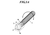
- the external appearance of the probe of this embodiment is shown in FIG. 1A.
- the basic configuration of the outer surface of the probe is composed of a bendable tube 1 and a tip mantle 2.
- the distal end opening of the tube 1 and the proximal end opening of the distal mantle 2 are joined and sealed so that liquid or the like does not enter.
- the distal end mantle 2 has a shape in which a cylindrical portion is connected to a hemispherical dome-shaped distal end portion, and is made of a molded resin or the like.
- the tip mantle 2 is made entirely or partially transparent.
- FIG. 1A and 1B show the internal configuration of the probe.
- 9a schematically shows a lens portion of the imaging camera 9.
- the torque coil 3 continues to the proximal end of the tube 1 and is rotated by an actuator such as a servo motor at the proximal end.
- the unit frame base end 4 a is formed in a disc shape and is fixed to the tip of the torque coil 3.
- the unit frame base end 4 a holds the irradiation optical fiber 5 and the light receiving optical fiber 6.
- the unit frame has a side wall portion (not shown) continuous to the peripheral portion of the unit frame base end portion 4a, and holds the condenser lens 7, the mirror 8, and the imaging camera 9.
- the axes of the irradiating optical fiber 5 and the light receiving optical fiber 6 face the tip direction of the probe, and are further arranged on the tip side in the order of the condenser lens 7, the mirror 8, and the imaging camera 9 as viewed from the optical fiber side. Yes.
- the imaging camera 9 is also provided with a lighting device (not shown) used for imaging.
- an imaging device is disposed on the distal end side of the probe with respect to the optical system that irradiates the observation target site of the living tissue and receives the reflected light from the observation target site. Since it is very difficult to place the irradiation optical fiber 5 and the light receiving optical fiber 6 by bypassing the imaging camera 9, the irradiation optical fiber 5, the light receiving optical fiber 6, and the light collecting optical fiber are collected by setting the imaging camera 9 at the distal end side.
- the imaging camera 9 can be disposed substantially coaxially with the optical system including the optical lens 7 and the mirror 8, and the diameter of the probe can be reduced. In addition, since the imaging camera 9 is arranged on the distal end side of the probe, it is easy to image in the distal direction of the probe.
- the base end of this probe is connected to a base unit (not shown).
- the base unit includes a light source of excitation light, a spectroscope, an image processing device, the actuator, and the like.
- the torque coil 3 is connected to the actuator, the proximal end of the irradiation optical fiber 5 is connected to the light source, the proximal end of the light receiving optical fiber 6 is connected to the spectroscope, and an image signal transmission cable (not shown) of the imaging camera 9 is connected to the image processing apparatus.
- the excitation light emitted from the irradiating optical fiber 5 is collected by the condenser lens 7, reflected by the mirror 8, emitted sideways, and irradiated onto the observation target portion of the living tissue. .
- fluorescence is generated by the excitation light at the irradiated observation target site.
- the reflected light including the generated fluorescence is incident on the mirror 8, reflected, condensed by the condenser lens 7, and incident on the light receiving optical fiber 6.
- the light guided by the light receiving optical fiber 6 is input to the spectroscope of the base unit.
- Fluorescence is broadly defined as an object irradiated with X-rays, ultraviolet rays, or visible light absorbs its energy, excites electrons, and releases excess energy as electromagnetic waves when it returns to the ground state.
- the excitation light reference light
- the excitation light causes fluorescence having a wavelength different from that wavelength to be generated as return light, which is detected and guided to the spectroscope of the base unit via the optical fiber 6 for light reception.
- the lesion state to be detected is detected.
- the imaging camera 9 is a camera equipped with an imaging element such as a CCD or C-MOS image sensor that captures a surface image of the observation target part.
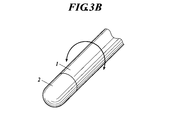
- This probe can take a form in which only the internal structure is rotated as shown in FIG. 3A and a form in which the entire structure including the outer surface constituent member and the internal structure is rotated as shown in FIG. 3B.
- the entire tip mantle 2 is transparent.
- a portion that does not cover the emission range of the excitation light, the incident range of the reflected light, and the visual field range of the imaging camera 9 may be non-transparent.
- the transparent portion of the tip mantle 2 is a portion that corresponds to at least the emission range of the excitation light, the incident range of the reflected light, and the visual field range of the imaging camera 9.
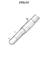
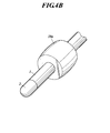
- the unit frame When the unit frame is rotated, it is effective to fix the probe by applying a structure in which the balloon 10a as the probe fixing means shown in FIGS. 4A and 4B is inflated and brought into contact with the inner wall of the lumen. It is.
- the unit frame 4 is formed in a cylindrical shape.
- a condensing lens 7, a mirror 8, and an imaging camera 9 are fixed inside the unit frame 4, and a rotation unit M is configured.
- a window 4 b is provided on the peripheral surface of the unit frame 4.
- the window 4b is made of a transparent member or formed by an opening.
- the window 4 b is a window for emitting excitation light, incident reflected light, emitting illumination light for imaging by the imaging camera 9, and imaging by the imaging camera 9.
- the axis X is a rotation axis extending in the longitudinal direction of the probe.
- the tip mantle 2 is entirely transparent, and the rotation unit M is rotated around the rotation axis X in the tip mantle 2 by the power transmitted through the torque coil 3. .
- the unit frame 4 also serves as a tip mantle. Therefore, the window 4b is not an opening but is made of a transparent member. In the configurations shown in FIGS.
- the unit frame 4 is connected to a torque tube 1A capable of transmitting torque
- the proximal end of the torque tube 1A is connected to an actuator
- the rotating unit M is connected via the torque tube 1A. Is rotated around the rotation axis X by the transmitted power.
- the torque tube 1A is constituted by, for example, a tube covered with a torque coil. Regardless of the configuration, the specific range may not be the window 4b and the whole may be transparent. Since the optical fibers 5 and 6 are connected to the rotation unit M, the rotation of the rotation unit M is restricted by a predetermined rotation angle. The rotation scanning described later is also performed by reversing at a predetermined rotation angle (for example, when reaching 360 ° or exceeding 360 °).
- the rotation unit M is rotationally scanned to obtain fluorescence intensity distribution information and image information. This is recorded in a memory mounted on the base unit or the like.
- the mirror 8 determines the incident direction of the reflected light reflected from the observation target site irradiated with the excitation light and incident on the probe and received and detected by the probe. To do. Since the relative angle between the incident direction of the reflected light and the viewing direction of the imaging camera 9 is constant even during rotational scanning, this can be specified, and can be specified in advance in the information processing apparatus as a constant.
- the fluorescence intensity distribution information and the image information can be displayed and output as a superimposed image in which the coordinates coincide.
- the balloon 10 a is formed as a part of the outer tube 10.
- the outer tube 10 is a multi-lumen tube having a hole 10c in the longitudinal direction in the outer skin 10b, and an internal space of a balloon 10a communicating with the hole 10c is formed between layers.
- the base end of the hole 10c is connected to an air pump, and the balloon 10a is inflated and deflated by supplying or sucking air from the hole 10c.
- the balloon 10a is inflated and the rotation axis X of the rotation unit M is fixed. Further, the probe main body including the rotation unit M moves in the axial direction with respect to the outer tube 10 and can be continuously scanned also in the axis X direction.
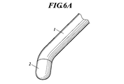
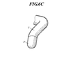
- the rotation unit M is compactly accommodated at the tip of this probe, as shown in FIGS. 6A, 6B, and 6C, only the tip is bent (FIG. 6A), only the middle step is bent (FIG. 6B),
- the tip part and the middle part can be bent in various ways, such as bending (FIG. 6C), can be inserted into the body through the nostril or mouth, and can smoothly advance through the body lumen. It can be rotated.
- the mirror 8 and the imaging camera 9 are drawn at an interval when they are mounted on the rotation unit M.
- the exit light path L1 of the excitation light and the incident light path L2 of the reflected light are perpendicular to the rotation axis X.
- the exit light path L1 of the excitation light and the incident light path L2 of the reflected light are 180 ° different from the field center YA of the imaging camera 9.
- the exit light path L1 of the excitation light and the incident light path L2 of the reflected light are inclined with respect to the axis of the visual field center YA of the imaging camera 9.
- the incident direction of the reflected light and the viewing angle ⁇ by the imaging camera 9 have a relative angle around the rotation axis X of the rotation unit M. Having a viewing angle ⁇ and a relative angle means not included in the viewing angle ⁇ range.
- the site to be observed by fluorescence detection is outside the field of view Y, and enters the field of view Y with a time difference due to the rotation of the rotation unit M.
- the image information is obtained and held in advance during rotational scanning, and the fluorescence intensity distribution information of the observation target part that has been imaged is obtained later.
- the output image is delayed with respect to the captured image, which may give the examiner a sense of incongruity.
- the viewing angle ⁇ of the imaging camera 9 includes a direction perpendicular to the axis X.
- the viewing angle ⁇ of the imaging camera 9 further includes the tip direction of the probe.
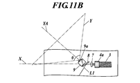
- the exit light path L1 of the excitation light and the incident light path L2 of the reflected light are inclined toward the visual field Y side of the imaging camera 9 from the direction perpendicular to the rotation axis X.
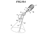
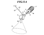
- the site to be observed by fluorescence detection can be placed in the visual field Y as shown in FIGS. 10A and 10B, as shown in FIGS. 11A and 11B.
- the site to be observed by fluorescence detection can be put in the visual field Y with a time difference by the rotation of the rotation unit M.
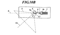
- FIG. 12B shows an arrangement schematic diagram in which the exit light path L1 of the excitation light and the incident light path L2 of the reflected light are inclined toward the field Y side when the field center YA is perpendicular to the rotation axis X. .
- the optical path for fluorescence observation can be tilted from the vertical direction so as to overlap the camera field of view.
- FIG. 12C The configuration shown in FIG. 12C is an example in which an optical element 11 having a condensing surface 11a in place of the condensing lens 7 and a reflecting surface 11b in place of the mirror 8 is applied.
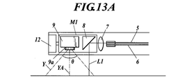
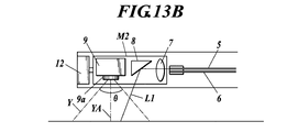
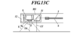
- the minimum elements to be mounted on the rotating unit are the imaging camera 9 and an optical element that determines the incident direction of reflected light to be received on the probe, that is, the fluorescence observation direction. Therefore, a rotation unit M1 having the mirror 8 and the imaging camera 9 as shown in FIG. 13A, or a rotation unit M2 having the condenser lens 7, the mirror 8 and the imaging camera 9 as shown in FIG. 13B, Various mounting forms such as a rotation unit M3 on which the optical element 11 and the imaging camera 9 are mounted as shown in FIG. 13C can be selected. By connecting these rotation units M1, M2, M3 to, for example, the output end of the servo motor 12 installed on the probe tip side, rotation scanning can be performed.
- FIG. 12B shows a configuration in which the fluorescence observation optical path is tilted with respect to the camera that captures the vertical direction. Furthermore, by using a camera with a wider viewing angle, it is possible to monitor the adhesion of dirt by including a fluorescence observation window (for example, the entire window 4b) in the field of view. That is, it is also effective to configure the field of view Y1 of the imaging camera 9 to include the excitation light on the outer surface of the probe and the passing portion Z1 of the reflected light to be received, like the field of view Y1 indicated by the broken line in FIG. 12B. . In this case, it is possible to detect the presence or absence of dirt on the outer surface that adversely affects the fluorescence measurement, which can be useful for maintaining measurement accuracy.
- a fluorescence observation window for example, the entire window 4b
- the optical fiber has been described as irradiating the observation target site with the excitation light and receiving the fluorescence generated due to the excitation light.
- the scattered light or Raman generated due to the irradiation light has been described.
- the scattered light may be received. Even in these cases, it is possible to diagnose a disease state such as degeneration of a living tissue or cancer.
- the probe according to the present invention can be used for observing living tissue for medical diagnosis.
Landscapes
- Physics & Mathematics (AREA)
- Health & Medical Sciences (AREA)
- Life Sciences & Earth Sciences (AREA)
- Spectroscopy & Molecular Physics (AREA)
- General Physics & Mathematics (AREA)
- Surgery (AREA)
- General Health & Medical Sciences (AREA)
- Pathology (AREA)
- Optics & Photonics (AREA)
- Nuclear Medicine, Radiotherapy & Molecular Imaging (AREA)
- Animal Behavior & Ethology (AREA)
- Molecular Biology (AREA)
- Veterinary Medicine (AREA)
- Public Health (AREA)
- Biophysics (AREA)
- Engineering & Computer Science (AREA)
- Biomedical Technology (AREA)
- Heart & Thoracic Surgery (AREA)
- Medical Informatics (AREA)
- Radiology & Medical Imaging (AREA)
- Immunology (AREA)
- Chemical & Material Sciences (AREA)
- Astronomy & Astrophysics (AREA)
- Analytical Chemistry (AREA)
- Biochemistry (AREA)
- Investigating, Analyzing Materials By Fluorescence Or Luminescence (AREA)
- Endoscopes (AREA)
- Instruments For Viewing The Inside Of Hollow Bodies (AREA)
Abstract
Description
このようなプローブには、照射光を生体の観察対象部位に照射し病変部から放射される放射光を受光する光ファイバー等の手段が備えられている。また、観察対象部位の周囲を視覚的に確認することも求められるため、観察対象部位の画像を撮像する撮像装置を併せ持つものが提案されている。
特許文献1記載のプローブにあっては、蛍光観察方向及び撮像方向がプローブの先端方向を向いているとともに、観察対象部位から反射した光を同一光路で受光し、光分岐手段で蛍光検出及び撮像のために分光する。
特許文献1,2記載のプローブにあっては、励起光を生体の観察対象部位に照射し観察対象部位からの反射光を受光する光学系と、撮像素子とがプローブの径方向に並んでおり、蛍光観察方向及び撮影方向はプローブ先端方向を向いている。
一方、特許文献4記載のプローブにあっては、励起光は円周方向および長手方向に走査し、複数の光検出素子が円周状に配設され、上記励起光による生体観察部位が発する蛍光を受光する。
特許文献1,2記載のプローブにあっては、励起光を生体の観察対象部位に照射し観察対象部位からの反射光を受光する光学系と、撮像素子とがプローブの径方向に並んでおり、蛍光観察方向及び撮影方向はプローブ先端方向を向いている。
そのため、プローブの細径化や、プローブの側方の撮像や蛍光観察が困難である。
特許文献4記載のプローブにあっては、蛍光を受光する手段のほかに観察対象部位の表面画像を撮像する撮像手段が備えられておらず、観察対象部位の表面を視覚的に観察することができない。
前記光学系に対して、当該プローブの先端側に前記撮像装置が配置されてなるプローブである。
前記光学素子は、前記照射用光ファイバー及び前記受光用光ファイバーより当該プローブの先端側に配置され、
前記反射面を光路に介在させることにより、当該プローブの長手方向に対する垂直方向又は傾斜した方向に沿って当該プローブに入射する前記放射光を受光する請求項1に記載のプローブである。
当該プローブの長手方向に延在する軸を回動軸として、受光する前記放射光の当該プローブへの入射方向と前記撮像装置の視野方向とを、前記回動軸周りの相対角度を固定して回動するプローブである。
前記回動軸周りに前記ユニットを回動させるための回動手段を有する請求項7に記載のプローブである。
前記光学系に対して、当該プローブの先端側に前記撮像装置が配置されてなり、
当該プローブの長手方向に延在する軸を回動軸として、受光する前記放射光の当該プローブへの入射方向と前記撮像装置の視野方向とを、前記回動軸周りの相対角度を固定して回動するプローブである。
また、当該プローブの先端側に撮像装置が配置されるため、当該プローブの先端方向の撮像も容易であるという効果がある。
ユニットフレーム基端部4aは円盤状に形成され、トルクコイル3の先端に固定される。また、ユニットフレーム基端部4aは、照射用光ファイバー5及び受光用光ファイバー6を保持している。ユニットフレームは、ユニットフレーム基端部4aの周部に連続した図示しない側壁部を有して、集光レンズ7、ミラー8及び撮像カメラ9を保持している。そして、トルクコイルが回動することにより、ユニットフレーム全体が回動する。
照射用光ファイバー5及び受光用光ファイバー6の軸は、本プローブの先端方向を向いており、更に先端側に、光ファイバー側からみて、集光レンズ7、ミラー8、撮像カメラ9の順で配置されている。撮像カメラ9には撮像時に用いる図示しない照明装置も設けられている。
すなわち、励起光を生体組織の観察対象部位に照射し観察対象部位からの反射光を受光する光学系に対して、当該プローブの先端側に撮像装置が配置される。撮像カメラ9を迂回して照射用光ファイバー5及び受光用光ファイバー6を配置することは非常に困難であるから、撮像カメラ9を先端側とすることにより、照射用光ファイバー5、受光用光ファイバー6、集光レンズ7及びミラー8からなる光学系とほぼ同軸に撮像カメラ9を配置することができ、本プローブを細径化することができる。また、本プローブの先端側に撮像カメラ9が配置されるため、本プローブの先端方向の撮像も容易である。
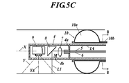
図5A,図5B,図5C,図5Dに示すようにユニットフレーム4は円筒状に形成される。ユニットフレーム4の内部に集光レンズ7、ミラー8及び撮像カメラ9が固定され、回動ユニットMが構成される。ユニットフレーム4の周面に窓4bが設けられる。窓4bは、透明部材で構成されるか、又は開口により形成される。窓4bは励起光の出射、反射光の入射、撮像カメラ9による撮像のための照明光の出射、及び撮像カメラ9による撮像のための窓である。軸Xは、本プローブの長手方向に延在する回動軸である。
図5A,図5Bに示す構成では、先端外套2は全部が透明とされ、回動ユニットMはトルクコイル3を介して伝達される動力により先端外套2内で回動軸X周りに回動する。
図5C,図5Dに示す構成では、ユニットフレーム4は、先端外套を兼ねている。したがって、窓4bは開口でなく透明部材で構成される。図5C,図5Dに示す構成では、ユニットフレーム4は、トルク伝達可能なトルクチューブ1Aに接続され、トルクチューブ1Aの基端がアクチュエータに接続されており、回動ユニットMはトルクチューブ1Aを介して伝達される動力により回動軸X周りに回動する。トルクチューブ1Aは、例えば、トルクコイルを被覆したチューブにより構成される。
いずれの構成にあっても、特定範囲を窓4bとせず全体を透明としてもよい。
回動ユニットMに光ファイバー5,6が接続されているため、回動ユニットMの回動は、所定の回転角で規制されるようにしてある。後述する回動走査も所定の回転角(例えば、360°に達するか又は360°を超えた時点)で反転して行われる。
上述した蛍光の検出と、撮像カメラ9による撮影を行いながら、回動ユニットMを回動走査して蛍光強度分布情報と画像情報を得る。ベースユニット等に搭載されるメモリにこれを記録する。本プローブが励起光を照射した観察対象部位から反射し本プローブに入射して本プローブが受光して検出する反射光の本プローブへの入射方向は、以上の構成にあってはミラー8が決定する。この反射光の入射方向と、撮像カメラ9の視野方向との相対角が回動走査中も一定しているのでこれを特定することができ、予め定数として情報処理装置に設定しておくことで蛍光強度分布情報と画像情報とを座標の一致させた重ね合わせ画像として表示出力することができる。
蛍光強度分布情報と画像情報とを取得するための回動ユニットMの回動走査中は、バルーン10aを膨張させて回動ユニットMの回動軸Xを固定して行う。また、回動ユニットMを含むプローブ本体は、アウターチューブ10に対して軸方向に移動し、軸X方向についても連続して走査可能である。
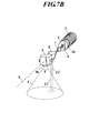
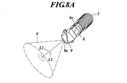
図7A,図7Bに分解斜視図として示す構成にあっては、励起光の出射光路L1及び反射光の入射光路L2は、本プローブの回動軸Xに対して垂直であり、撮像カメラ9の視野Yと同方向を向いている。なお、図7Aではミラー8と撮像カメラ9とを離して図示しているが、図7Bに示すようにミラー8と撮像カメラ9とを回動ユニットM上に搭載されたときの間隔で描くと、蛍光検出による観察対象部位は視野Y内にある。そして、図8A,図8B,図8Cに示すように回動走査が行われる。なお、図12Aに本構成の配置模式図を示した。
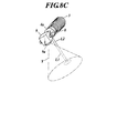
図9A示す構成では、励起光の出射光路L1及び反射光の入射光路L2は撮像カメラ9の視野中心YAと180°異なっている。
図9B示す構成では、励起光の出射光路L1及び反射光の入射光路L2は撮像カメラ9の視野中心YAの軸線に対して傾斜している。
すなわち、図9A,図9Bのいずれの構成にあっても、反射光の入射方向と、撮像カメラ9による視野角θとが、回動ユニットMの回動軸X周りに相対角を有する。視野角θと相対角を有するとは、視野角θ範囲内に含まれないことを意味する。これにより、蛍光検出による観察対象部位は視野Y外にあり、回動ユニットMの回動によって視野Y内に時間差をもって入ることとなる。
本構成を用いて、回動走査中に画像情報を先に得て保持し、撮像が済んだ観察対象部位の蛍光強度分布情報を後で得て、両情報を合成して表示出力すると、リアルタイムの撮影画像に対して出力画像が遅れてしまい、検査者に対して違和感を与えるおそれがある。
したがって、本構成を用いて蛍光強度分布情報を先に得て保持し、蛍光測定が済んだ観察対象部位の画像情報を後で得て、両情報を合成することが好ましい。これにより、検査者に対して撮像時に対して時間差が小さく違和感のない画像を表示することができるという利点がある。
また、図9A,図9Bに示したように、ミラー8の撮像カメラ9に対する角度を選択することができることによって、撮像カメラ9から延出するケーブルとミラー8とが干渉しない配置を選択でき、よりミラー8と撮像カメラ9とを近接配置して、回動ユニットMを短くコンパクトにすることができるという利点がある。
図10A,図10B及び図11A,図11Bに示すように、励起光の出射光路L1及び反射光の入射光路L2を、回動軸Xに対する垂直方向よりも撮像カメラ9の視野Y側に傾斜した方向とする。これにより、視野中心YAがプローブ先端側に傾いていても、図10A,図10Bに示すように蛍光検出による観察対象部位を視野Y内に入れることができ、図11A,図11Bに示すように、蛍光検出による観察対象部位を回動ユニットMの回動によって視野Y内に時間差をもって入れることができる。図12Bには、視野中心YAが回動軸Xに対して垂直な場合において励起光の出射光路L1及び反射光の入射光路L2を視野Y側に傾斜させた構成の配置模式図を示した。ミラー8の向きを調整することで、蛍光観察用光路を垂直方向から傾け、カメラ視野に重なるようにすることができる。
回動ユニットに搭載すべき最小要素は、撮像カメラ9と、受光する反射光の当該プローブへの入射方向、すなわち、蛍光観察方向を決定する光学素子である。したがって、図13Aに示すようなミラー8と撮像カメラ9とを搭載した回動ユニットM1や、図13Bに示すような集光レンズ7とミラー8と撮像カメラ9とを搭載した回動ユニットM2、図13Cに示すような光学素子11と撮像カメラ9とを搭載した回動ユニットM3など、様々な搭載形態を選択できる。これらの回動ユニットM1,M2,M3を、例えばプローブ先端側に設置したサーボモータ12の出力端に接続することによって、回動走査を実施することができる。
すなわち、図12Bに破線で示した視野Y1のように、撮像カメラ9の視野Y1がプローブの外表面上の励起光及び受光する反射光の通過部Z1を含むように構成することも有効である。この場合、蛍光測定に悪影響を与える外表面の汚れの有無を検出することが可能となり、測定精度を維持することに役立たせることができる。
1A トルクチューブ
2 先端外套
3 トルクコイル
4 ユニットフレーム
4a ユニットフレーム基端部
4b 窓
5 照射用光ファイバー
6 受光用光ファイバー
7 集光レンズ
8 ミラー(又はプリズム)
9 撮像カメラ
10 アウターチューブ
10a バルーン
11 光学素子
11a 集光面
11b 反射面
12 サーボモータ
L1 出射光路
L2 入射光路
M 回動ユニット
M1 回動ユニット
M2 回動ユニット
M3 回動ユニット
X 回動軸
Y 視野
Y1 視野
YA 視野中心
Z1 通過部
θ 視野角
Claims (18)
- 生体組織の観察対象部位に照射光を照射して観察対象部位から放射される放射光を受光するための光学系と、観察対象部位の表面画像を撮像する撮像装置とを備えるプローブにおいて、
前記光学系に対して、当該プローブの先端側に前記撮像装置が配置されてなるプローブ。 - 前記光学系は、前記照射光の照射用光ファイバーと、前記放射光の受光用光ファイバーと、反射面を有した光学素子とを備え、
前記光学素子は、前記照射用光ファイバー及び前記受光用光ファイバーより当該プローブの先端側に配置され、
前記反射面を光路に介在させることにより、当該プローブの長手方向に対する垂直方向又は傾斜した方向に沿って当該プローブに入射する前記放射光を受光する請求項1に記載のプローブ。 - 前記撮像装置の視野角は、当該プローブの先端方向に垂直な方向を含む請求項1又は請求項2に記載のプローブ。
- 前記撮像装置の視野角は、当該プローブの先端方向を含む請求項3に記載のプローブ。
- 前記撮像装置の視野は、当該プローブの外表面上の前記照射光及び前記放射光の通過部を含む請求項3又は請求項4に記載のプローブ。
- 前記光学系は、前記照射光に起因して生じる蛍光、散乱光又はラマン散乱光を受光することを特徴とする請求項1から請求項5のうちいずれか一に記載のプローブ。
- 生体組織の観察対象部位に照射光を照射して観察対象部位から放射される放射光を受光するための光学系と、観察対象部位の表面画像を撮像する撮像装置とを備えるプローブにおいて、
当該プローブの長手方向に延在する軸を回動軸として、受光する前記放射光の当該プローブへの入射方向と前記撮像装置の視野方向とを、前記回動軸周りの相対角度を固定して回動するプローブ。 - 前記放射光の当該プローブへの入射方向を決定する光学素子及び前記撮像装置がユニットに取り付けられ、
前記回動軸周りに前記ユニットを回動させるための回動手段を有する請求項7に記載のプローブ。 - 前記回動軸に対する垂直方向又は傾斜した方向に沿って当該プローブに入射する前記放射光を受光する請求項7又は請求項8に記載のプローブ。
- 同時に前記撮像装置による視野内にあるか又は前記回動によって前記撮像装置による視野内に時間差をもって入る観察対象部位から放射される前記放射光を受光する請求項9に記載のプローブ。
- 前記入射方向が、前記回動軸に対する垂直方向よりも前記撮像装置の視野側に傾斜した方向とされることにより、同時に前記撮像装置による視野内にあるか又は前記回動によって前記撮像装置による視野内に時間差をもって入る観察対象部位から放射される前記放射光を受光する請求項10に記載のプローブ。
- 同時において前記撮像装置による視野外にあり、前記回動によって前記撮像装置による視野内に時間差をもって入る観察対象部位から放射される前記放射光を受光する請求項9に記載のプローブ。
- 前記入射方向と、前記撮像装置による視野角とが、前記回動軸周りに相対角を有することにより、同時において前記撮像装置による視野外にあり、前記回動によって前記撮像装置による視野内に時間差をもって入る観察対象部位から放射される前記放射を受光する請求項12に記載のプローブ。
- 前記撮像装置の視野角は、前記回動軸に垂直な方向を含む請求項7から請求項13のうちいずれか一に記載のプローブ。
- 前記撮像装置の視野角は、当該プローブの先端方向を含む請求項14に記載のプローブ。
- 前記撮像装置の視野は、当該プローブの外表面上の前記照射光及び前記放射光の通過部を含む請求項14又は請求項15に記載のプローブ。
- 前記光学系は、前記照射光に起因して生じる蛍光、散乱光又はラマン散乱光を受光することを特徴とする請求項7から請求項16のうちいずれか一に記載のプローブ。
- 生体組織の観察対象部位に照射光を照射して観察対象部位から放射される放射光を受光するための光学系と、観察対象部位の表面画像を撮像する撮像装置とを備えるプローブにおいて、
前記光学系に対して、当該プローブの先端側に前記撮像装置が配置されてなり、
当該プローブの長手方向に延在する軸を回動軸として、受光する前記放射光の当該プローブへの入射方向と前記撮像装置の視野方向とを、前記回動軸周りの相対角度を固定して回動するプローブ。
Priority Applications (4)
| Application Number | Priority Date | Filing Date | Title |
|---|---|---|---|
| JP2012511660A JP5708643B2 (ja) | 2010-04-23 | 2011-04-19 | プローブ |
| CN201180019771.XA CN102858224B (zh) | 2010-04-23 | 2011-04-19 | 探头 |
| US13/643,029 US9277852B2 (en) | 2010-04-23 | 2011-04-19 | Probe |
| EP11771996.3A EP2561795A4 (en) | 2010-04-23 | 2011-04-19 | PROBE |
Applications Claiming Priority (4)
| Application Number | Priority Date | Filing Date | Title |
|---|---|---|---|
| JP2010-099868 | 2010-04-23 | ||
| JP2010-099867 | 2010-04-23 | ||
| JP2010099868 | 2010-04-23 | ||
| JP2010099867 | 2010-04-23 |
Publications (1)
| Publication Number | Publication Date |
|---|---|
| WO2011132661A1 true WO2011132661A1 (ja) | 2011-10-27 |
Family
ID=44834180
Family Applications (1)
| Application Number | Title | Priority Date | Filing Date |
|---|---|---|---|
| PCT/JP2011/059600 Ceased WO2011132661A1 (ja) | 2010-04-23 | 2011-04-19 | プローブ |
Country Status (5)
| Country | Link |
|---|---|
| US (1) | US9277852B2 (ja) |
| EP (1) | EP2561795A4 (ja) |
| JP (1) | JP5708643B2 (ja) |
| CN (1) | CN102858224B (ja) |
| WO (1) | WO2011132661A1 (ja) |
Cited By (3)
| Publication number | Priority date | Publication date | Assignee | Title |
|---|---|---|---|---|
| CN102551677A (zh) * | 2012-03-06 | 2012-07-11 | 天津大学 | 用于漫射光断层成像的内窥式旋转探头 |
| WO2021132153A1 (ja) * | 2019-12-26 | 2021-07-01 | 富士フイルム株式会社 | 内視鏡及び内視鏡システム |
| CN113952010A (zh) * | 2021-12-06 | 2022-01-21 | 中国科学院长春光学精密机械与物理研究所 | 一种新型可视化产钳系统 |
Families Citing this family (10)
| Publication number | Priority date | Publication date | Assignee | Title |
|---|---|---|---|---|
| CN108324230B (zh) * | 2013-02-01 | 2021-06-22 | 德卡产品有限公司 | 具有可摇摄相机的内窥镜 |
| US9194690B2 (en) * | 2013-03-04 | 2015-11-24 | Corning Incorporated | Power transmission and sensing device |
| US9195044B2 (en) | 2013-08-15 | 2015-11-24 | Siemens Energy, Inc | Optical probe having an inner tube with separable tube sections to house optical elements |
| US9182285B2 (en) * | 2013-08-15 | 2015-11-10 | Siemens Energy, Inc. | Methods regarding optical probe having an inner tube with separable tube sections to house optical elements |
| US9518895B2 (en) * | 2013-08-15 | 2016-12-13 | Siemens Energy, Inc. | Optical probe with improved affixing structure for supporting a light-redirecting element |
| US10031021B2 (en) * | 2014-02-21 | 2018-07-24 | Shimadzu Corporation | Optical measurement probe and optical measurement device provided with the same having a light guide with a reflection surface for reflecting light and causing light to enter the light guide |
| DE112016006667T5 (de) * | 2016-03-31 | 2018-12-20 | Honda Motor Co., Ltd. | Optische messsonde und damit versehene optische messvor-richtung |
| CN107255632A (zh) * | 2017-06-27 | 2017-10-17 | 上海化工研究院有限公司 | 一种用于探测较深层固体样品的拉曼光谱探头延伸装置 |
| US12326553B2 (en) | 2022-03-25 | 2025-06-10 | General Electric Company | Tool stabilization mechanism and related methods |
| EP4249984A1 (en) * | 2022-03-25 | 2023-09-27 | General Electric Company | Tool stabilization mechanism and related methods |
Citations (9)
| Publication number | Priority date | Publication date | Assignee | Title |
|---|---|---|---|---|
| JPS63164932A (ja) * | 1986-12-27 | 1988-07-08 | オリンパス光学工業株式会社 | 内視鏡装置 |
| JPH04341232A (ja) * | 1991-03-11 | 1992-11-27 | Olympus Optical Co Ltd | 電子内視鏡システム |
| JPH09294707A (ja) | 1996-04-30 | 1997-11-18 | Fuji Photo Film Co Ltd | 内視鏡 |
| JPH10127562A (ja) | 1996-10-28 | 1998-05-19 | Fuji Photo Film Co Ltd | 蛍光内視鏡 |
| JP2001079007A (ja) * | 1999-09-13 | 2001-03-27 | Olympus Optical Co Ltd | 光プローブ装置 |
| JP2003204926A (ja) * | 2002-01-11 | 2003-07-22 | Olympus Optical Co Ltd | 内視鏡 |
| JP2005319212A (ja) | 2004-05-11 | 2005-11-17 | Pentax Corp | 蛍光内視鏡装置 |
| JP2006087447A (ja) * | 2004-09-21 | 2006-04-06 | Michiaki Nagai | スキャナシステム |
| JP2008048787A (ja) | 2006-08-22 | 2008-03-06 | Olympus Corp | 内視鏡装置、及び内視鏡プローブ |
Family Cites Families (8)
| Publication number | Priority date | Publication date | Assignee | Title |
|---|---|---|---|---|
| JPS58216212A (ja) * | 1982-06-11 | 1983-12-15 | Sumitomo Electric Ind Ltd | 視野回転機構付イメ−ジフアイバ |
| JPH0211117A (ja) * | 1988-06-30 | 1990-01-16 | Toshiba Corp | 電子内視鏡装置 |
| JPH07327916A (ja) * | 1994-06-02 | 1995-12-19 | Olympus Optical Co Ltd | 視野方向可変型内視鏡 |
| US5797836A (en) * | 1995-06-07 | 1998-08-25 | Smith & Nephew, Inc. | Endoscope with relative rotation and axial motion between an optical element and an imaging device |
| US6428470B1 (en) * | 1995-09-15 | 2002-08-06 | Pinotage, Llc | Imaging system and components thereof |
| US7175593B2 (en) * | 2000-08-30 | 2007-02-13 | Durell & Gitelis, Inc. | Variable view arthroscope with charge coupled device |
| US7018309B2 (en) | 2004-05-04 | 2006-03-28 | Bridgestone Sports Co., Ltd. | Golf ball |
| CN113520315A (zh) * | 2007-01-19 | 2021-10-22 | 桑尼布鲁克健康科学中心 | 具有组合的超声和光学成像装置的成像探头 |
-
2011
- 2011-04-19 US US13/643,029 patent/US9277852B2/en not_active Expired - Fee Related
- 2011-04-19 CN CN201180019771.XA patent/CN102858224B/zh not_active Expired - Fee Related
- 2011-04-19 EP EP11771996.3A patent/EP2561795A4/en not_active Withdrawn
- 2011-04-19 WO PCT/JP2011/059600 patent/WO2011132661A1/ja not_active Ceased
- 2011-04-19 JP JP2012511660A patent/JP5708643B2/ja not_active Expired - Fee Related
Patent Citations (9)
| Publication number | Priority date | Publication date | Assignee | Title |
|---|---|---|---|---|
| JPS63164932A (ja) * | 1986-12-27 | 1988-07-08 | オリンパス光学工業株式会社 | 内視鏡装置 |
| JPH04341232A (ja) * | 1991-03-11 | 1992-11-27 | Olympus Optical Co Ltd | 電子内視鏡システム |
| JPH09294707A (ja) | 1996-04-30 | 1997-11-18 | Fuji Photo Film Co Ltd | 内視鏡 |
| JPH10127562A (ja) | 1996-10-28 | 1998-05-19 | Fuji Photo Film Co Ltd | 蛍光内視鏡 |
| JP2001079007A (ja) * | 1999-09-13 | 2001-03-27 | Olympus Optical Co Ltd | 光プローブ装置 |
| JP2003204926A (ja) * | 2002-01-11 | 2003-07-22 | Olympus Optical Co Ltd | 内視鏡 |
| JP2005319212A (ja) | 2004-05-11 | 2005-11-17 | Pentax Corp | 蛍光内視鏡装置 |
| JP2006087447A (ja) * | 2004-09-21 | 2006-04-06 | Michiaki Nagai | スキャナシステム |
| JP2008048787A (ja) | 2006-08-22 | 2008-03-06 | Olympus Corp | 内視鏡装置、及び内視鏡プローブ |
Non-Patent Citations (1)
| Title |
|---|
| See also references of EP2561795A4 * |
Cited By (3)
| Publication number | Priority date | Publication date | Assignee | Title |
|---|---|---|---|---|
| CN102551677A (zh) * | 2012-03-06 | 2012-07-11 | 天津大学 | 用于漫射光断层成像的内窥式旋转探头 |
| WO2021132153A1 (ja) * | 2019-12-26 | 2021-07-01 | 富士フイルム株式会社 | 内視鏡及び内視鏡システム |
| CN113952010A (zh) * | 2021-12-06 | 2022-01-21 | 中国科学院长春光学精密机械与物理研究所 | 一种新型可视化产钳系统 |
Also Published As
| Publication number | Publication date |
|---|---|
| JP5708643B2 (ja) | 2015-04-30 |
| JPWO2011132661A1 (ja) | 2013-07-18 |
| US9277852B2 (en) | 2016-03-08 |
| CN102858224B (zh) | 2015-04-01 |
| EP2561795A1 (en) | 2013-02-27 |
| EP2561795A4 (en) | 2013-09-25 |
| CN102858224A (zh) | 2013-01-02 |
| US20130038872A1 (en) | 2013-02-14 |
Similar Documents
| Publication | Publication Date | Title |
|---|---|---|
| JP5708643B2 (ja) | プローブ | |
| JP5118867B2 (ja) | 内視鏡観察装置および内視鏡の作動方法 | |
| US10314490B2 (en) | Method and device for multi-spectral photonic imaging | |
| EP2046188B1 (en) | Capsule camera with variable illumination of the surrounding tissue | |
| JP3579638B2 (ja) | 内視鏡装置 | |
| JP5461753B2 (ja) | 内視鏡装置 | |
| US20130070255A1 (en) | Probe for optical tomograpic image measurement device and method for adjusting probe | |
| JP5314841B2 (ja) | 内視鏡装置、及び内視鏡プローブ | |
| CN103118582B (zh) | 荧光观察装置 | |
| WO2014045581A1 (ja) | 光学測定装置およびプローブシステム | |
| JP7160093B2 (ja) | 医用画像撮像装置 | |
| US20070293766A1 (en) | Transmission Based Imaging for Spectroscopic Analysis | |
| WO2010061471A1 (ja) | 生体観察装置 | |
| KR101887033B1 (ko) | 치아 구조/기능 영상을 위한 복합영상장치 | |
| JP2012050487A (ja) | プローブ | |
| JP5928461B2 (ja) | プローブ | |
| JP5708659B2 (ja) | プローブ及び測定システム | |
| JP5648456B2 (ja) | プローブ | |
| JP2011127924A (ja) | イメージングプローブ | |
| JP5811049B2 (ja) | プローブ | |
| JP2008295744A (ja) | 生体観察装置 |
Legal Events
| Date | Code | Title | Description |
|---|---|---|---|
| WWE | Wipo information: entry into national phase |
Ref document number: 201180019771.X Country of ref document: CN |
|
| 121 | Ep: the epo has been informed by wipo that ep was designated in this application |
Ref document number: 11771996 Country of ref document: EP Kind code of ref document: A1 |
|
| WWE | Wipo information: entry into national phase |
Ref document number: 2012511660 Country of ref document: JP |
|
| WWE | Wipo information: entry into national phase |
Ref document number: 2011771996 Country of ref document: EP |
|
| NENP | Non-entry into the national phase |
Ref country code: DE |
|
| WWE | Wipo information: entry into national phase |
Ref document number: 13643029 Country of ref document: US |