WO2011151902A1 - Procédé et dispositif pour remplacement de gaz de récipient - Google Patents
Procédé et dispositif pour remplacement de gaz de récipient Download PDFInfo
- Publication number
- WO2011151902A1 WO2011151902A1 PCT/JP2010/059370 JP2010059370W WO2011151902A1 WO 2011151902 A1 WO2011151902 A1 WO 2011151902A1 JP 2010059370 W JP2010059370 W JP 2010059370W WO 2011151902 A1 WO2011151902 A1 WO 2011151902A1
- Authority
- WO
- WIPO (PCT)
- Prior art keywords
- replacement
- gas
- opening
- nozzle
- height
- Prior art date
- Legal status (The legal status is an assumption and is not a legal conclusion. Google has not performed a legal analysis and makes no representation as to the accuracy of the status listed.)
- Ceased
Links
Images


Classifications
-
- B—PERFORMING OPERATIONS; TRANSPORTING
- B67—OPENING, CLOSING OR CLEANING BOTTLES, JARS OR SIMILAR CONTAINERS; LIQUID HANDLING
- B67C—CLEANING, FILLING WITH LIQUIDS OR SEMILIQUIDS, OR EMPTYING, OF BOTTLES, JARS, CANS, CASKS, BARRELS, OR SIMILAR CONTAINERS, NOT OTHERWISE PROVIDED FOR; FUNNELS
- B67C3/00—Bottling liquids or semiliquids; Filling jars or cans with liquids or semiliquids using bottling or like apparatus; Filling casks or barrels with liquids or semiliquids
- B67C3/02—Bottling liquids or semiliquids; Filling jars or cans with liquids or semiliquids using bottling or like apparatus
- B67C3/06—Bottling liquids or semiliquids; Filling jars or cans with liquids or semiliquids using bottling or like apparatus using counterpressure, i.e. filling while the container is under pressure
- B67C3/10—Bottling liquids or semiliquids; Filling jars or cans with liquids or semiliquids using bottling or like apparatus using counterpressure, i.e. filling while the container is under pressure preliminary filling with inert gases, e.g. carbon dioxide
-
- B—PERFORMING OPERATIONS; TRANSPORTING
- B65—CONVEYING; PACKING; STORING; HANDLING THIN OR FILAMENTARY MATERIAL
- B65B—MACHINES, APPARATUS OR DEVICES FOR, OR METHODS OF, PACKAGING ARTICLES OR MATERIALS; UNPACKING
- B65B31/00—Packaging articles or materials under special atmospheric or gaseous conditions; Adding propellants to aerosol containers
- B65B31/04—Evacuating, pressurising or gasifying filled containers or wrappers by means of nozzles through which air or other gas, e.g. an inert gas, is withdrawn or supplied
- B65B31/043—Evacuating, pressurising or gasifying filled containers or wrappers by means of nozzles through which air or other gas, e.g. an inert gas, is withdrawn or supplied the nozzles acting horizontally between an upper and a lower part of the container or wrapper, e.g. between container and lid
-
- B—PERFORMING OPERATIONS; TRANSPORTING
- B65—CONVEYING; PACKING; STORING; HANDLING THIN OR FILAMENTARY MATERIAL
- B65B—MACHINES, APPARATUS OR DEVICES FOR, OR METHODS OF, PACKAGING ARTICLES OR MATERIALS; UNPACKING
- B65B31/00—Packaging articles or materials under special atmospheric or gaseous conditions; Adding propellants to aerosol containers
- B65B31/04—Evacuating, pressurising or gasifying filled containers or wrappers by means of nozzles through which air or other gas, e.g. an inert gas, is withdrawn or supplied
-
- B—PERFORMING OPERATIONS; TRANSPORTING
- B67—OPENING, CLOSING OR CLEANING BOTTLES, JARS OR SIMILAR CONTAINERS; LIQUID HANDLING
- B67C—CLEANING, FILLING WITH LIQUIDS OR SEMILIQUIDS, OR EMPTYING, OF BOTTLES, JARS, CANS, CASKS, BARRELS, OR SIMILAR CONTAINERS, NOT OTHERWISE PROVIDED FOR; FUNNELS
- B67C3/00—Bottling liquids or semiliquids; Filling jars or cans with liquids or semiliquids using bottling or like apparatus; Filling casks or barrels with liquids or semiliquids
- B67C3/02—Bottling liquids or semiliquids; Filling jars or cans with liquids or semiliquids using bottling or like apparatus
- B67C3/22—Details
- B67C3/222—Head-space air removing devices, e.g. by inducing foam
-
- F—MECHANICAL ENGINEERING; LIGHTING; HEATING; WEAPONS; BLASTING
- F04—POSITIVE - DISPLACEMENT MACHINES FOR LIQUIDS; PUMPS FOR LIQUIDS OR ELASTIC FLUIDS
- F04F—PUMPING OF FLUID BY DIRECT CONTACT OF ANOTHER FLUID OR BY USING INERTIA OF FLUID TO BE PUMPED; SIPHONS
- F04F99/00—Subject matter not provided for in other groups of this subclass
Definitions
- the present invention relates to a gas replacement method and apparatus for a container in which an inert gas is blown into the head space of a content filling container such as a beverage can to replace the residual gas in the head space, and in particular, an undercover gassing for a can lid winding machine
- the present invention relates to a method and an apparatus.
- the can lid is formed between the gas turret 1 and the seaming turret 2 as shown in FIG.
- An undercover gassing method is widely used in which gas replacement is performed by blowing a replacement gas between the can lid and the can body opening immediately before the cover 33 covers the opening of the can body 30. Since the replacement efficiency of the method is low, the flow rate of the replacement gas used to achieve a replacement rate higher than a predetermined level has been remarkably increased with the recent increase in production line speed and diversification of contents. In addition, the amount of liquid spilled from the can tends to increase as the replacement gas flow rate increases.
- a large replacement gas flow path to the replacement nozzle is formed (provided with a so-called buffer), and a group of blowout holes of the nozzle is blown toward the flange of the can lid.
- a second gas jet hole that blows into the space under the lid in a right angle direction and a third gas jet hole that blows out to the wall portion below the can mouth edge in three stages in the vertical direction Patent Document 1
- a branch body that branches the gas flow left and right at the center of the replacement gas injection flow path and forming nozzles on the left and right
- the replacement gas injected from the pair of nozzles collides with the center of the upper space in the can
- the replacement gas is directed to the liquid level of the head space of the can (Patent Document 2), and the replacement gas blown out from the pair of left and right outlets is made to collide in a substantially linear collision region. Things (patents Document 3,4) it has been proposed.
- FIG. 11 and 12 show an example of a conventional nozzle body 50 provided in a pocket portion of a gas turret as shown in Patent Document 3.
- FIG. The replacement gas flow paths 51a and 51b branched to the left and right are partitioned by a wind direction adjusting plate 52 to form opposed outlets 53a and 53b, and the replacement gas is blown symmetrically between the can body and the can lid from the outlet.
- the conventional nozzle body is disposed on the gas turret body at the same level position as the nozzle body, as shown in the front view of the gas turret pocket. Since the finger 55 is provided, the angle ⁇ between the outermost walls 54a and 54b of the nozzle outlet can be formed only to 90 ° or less (usually 80 °).
- the most ideal gas replacement method is to reduce the amount of residual oxygen in the container, the amount of consumption of the replacement gas, and the amount of liquid spillage from the container at the time of replacement. All of these methods are aimed at achieving this ideal technical challenge, but these challenges are technically conflicting and if one requirement is met, the other requirement must be sacrificed, It is difficult to achieve three quantities at the same time, and a satisfactory one has not yet been obtained.
- Patent Document 1 if the replacement gas flow rate is increased, a reduction in the amount of residual oxygen (that is, an improvement in the replacement rate) can be obtained, but a large amount of replacement gas is consumed. There is.
- An object of the present invention is to provide a gas replacement method and apparatus that can dramatically reduce the gas replacement rate and increase the gas replacement rate.
- the present inventor has configured the opening angle between the outermost walls of the nozzle opening in a specific range larger than that of the conventional nozzle in the undercover gassing device.
- the gas replacement method of the present invention for solving the above problems is as follows.
- the replacement nozzle partitions a nozzle port outermost wall with a wind direction adjusting plate to form a plurality of outlets.
- the replacement gas jets that are blown symmetrically from the outlet center line in the radial direction of the vessel, the replacement gas jets blown along the outermost wall of the nozzle port are blown out so that the angle between them is 100 ° to 130 °. It is a feature.
- the replacement nozzle is formed by partitioning the outermost wall of the nozzle opening with a plurality of air direction adjusting plates to form a plurality of outlets,
- the displacement gas flow to be blown in is a depth of 1/3 or more of the height of the can neck portion downward from the can opening end, or a depth of 3 mm or more from the can opening end toward the can body, and the can lid height upward. It blows out from the said replacement nozzle over the range above 3 mm or more from the above height or can opening end.
- the range of the replacement gas flow blown from the replacement nozzle is the end of the can opening when the can body that performs gas replacement is a can body that has been subjected to netine processing of a normal height (height of the neck-in processing portion: 5 to 20 mm). It is only necessary to cover a depth of 1/3 or more of the height of the can neck portion downward from the can opening when the can body not subjected to the neck-in process or the neck-in processed portion is a long can body Cover the depth of 3 mm or more in the can body direction.
- the height of the can lid is the normal can lid (chuck wall height: 4 to 8 mm)
- the height can be higher than the can lid height from the can opening end.
- the chuck wall portion is set to a range of 3 mm or more from the end of the can opening.
- the gas replacement apparatus of the present invention that achieves the above-mentioned problems is as follows.
- the replacement nozzle partitions the nozzle wall outermost wall from each other with a wind direction adjusting plate to make the container radial center line symmetrical
- a plurality of outlets for discharging the replacement gas toward the opening of the container are arranged on an arc, and the opening angle between the outermost walls of the nozzle opening is 100 ° to 130 °.
- another gas replacement device of the present invention that solves the above problems is (2) a gas replacement method that replaces residual gas in a head space by blowing a replacement gas into a head space of a content filling container from a replacement nozzle.
- the replacement nozzle forms a plurality of outlets by partitioning the outermost wall of the nozzle opening with a plurality of wind direction adjusting plates, and the replacement gas flow blown from the replacement nozzle has a height of the can neck portion downward from the can opening end. Blow out from the replacement nozzle at a depth of 1/3 or more, or 3 mm or more in the can body direction from the can opening end, and above the can lid height or 3 mm or more upward from the can opening end.
- the replacement gas is blown from the side toward the gap between the can lid and the can body opening immediately before the can lid covers the opening of the content-filled can body.
- another gas replacement apparatus of the present invention that solves the above-described problems can increase the replacement rate with a smaller amount of replacement gas and reduce liquid spillage by providing the configurations of (1) and (2). Is made possible.
- the wind direction adjusting plates are preferably arranged in parallel to each other.
- the improvement of the conventional technique can ensure a replacement rate equal to or higher than that of the conventional one with a small replacement gas flow rate, and the amount of spillage can be reduced without limit. Has a special effect.
- FIG. 10 is a schematic plan view of a conventional gas replacement device for a parallel comb-shaped nozzle, and is a cross-sectional plan view of a replacement gas flow path excluding finger portions. It is a principal part front view seen from the circular-arc-shaped recessed part side of the gas displacement apparatus shown in FIG.
- FIG. 1 is a plan cross-sectional view of a nozzle body of an undercover gassing device according to an embodiment of a gas replacement device of the present invention so as to face an arcuate recess (pocket) 3 of a gas turret 1 shown in FIG. Provided.
- a nozzle body 11 is fixed to the upper surface of the gas turret body 10 of the gas turret 1, and a replacement gas flow path 12 communicating with each arcuate recess 3 is formed inside the nozzle body.
- the replacement gas flow path 12 leading to the replacement gas supply port 14 is formed in a straight having a substantially equal height, as shown in FIG. It is not done.
- the replacement gas flow path 12 extends in a tapered shape from the replacement gas supply port 14 toward the arcuate recess 3, but is branched into the gas flow paths 12 a and 12 b by the branch plate 13 on the way, and the replacement of the tip portion is performed.
- the gas blowout ports (hereinafter referred to as blowout ports) are partitioned by a plurality of parallel wind direction adjusting plates 16a and 16b, and formed as a group of a plurality of parallel blowout ports 15a and 15b toward the arc-shaped concave portion to constitute an injection nozzle. ing.
- each outlet 15a and 15b are formed symmetrically with respect to the center line L, respectively, and the angle ⁇ between the outermost walls 17a and 17b of the outlets is an angle of 100 ° to 130 °, and the wind direction adjusting plate 16a 16b are provided in parallel with the outermost walls 17a and 17b, respectively. Accordingly, in the present embodiment, each outlet is also formed with an angle ⁇ between the opposing outlets of 100 ° to 130 °, and the replacement gases blown from the opposing outlets are mutually on the center line L. It is supposed to collide.
- the angle between the outlets 100 ° to 130 ° is as follows, compared to the angle between the outlets of the conventional gas turret being about 80 ° as shown in FIGS. It is formed at a large angle for technical reasons. That is, the present inventor is in the process of studying the reason why the gas replacement rate is not improved by the conventional undercover gassing method.
- the nozzle opening base outer position indicated by the phantom line in FIG. As a means to solve the problem that vortex is generated in Z, gas stagnation occurs in that portion, gas replacement is not performed well, and liquid spillage generated during gas replacement occurs, the opening area width of the outlet ( It has been found that these problems can be solved by increasing the blowing angle.
- the conventional gas turret 1 has fingers for positioning and transporting can lids 33 placed on the outer periphery of the pocket at both ends of the arcuate recess 3 of the gas turret body 10 in the pocket as shown in FIGS. 55 is provided, and the nozzle body 50 is provided between them. Therefore, the installation range of the outlets arranged on the peripheral surface of the pocket is naturally limited, and can be installed only within a maximum of 100 °, usually only about 80 °. Not formed.
- the conventional finger 55 is removed from the gas turret body 10 and the nozzle body is expanded to the position where the conventional finger is located.
- the fingers 4 and 4 were provided on the nozzle body 11 as shown in FIGS.
- the range of the replacement nozzle can be formed so that the angle between the outermost walls 17a and 17b can be increased to 130 ° as shown in FIG. 1, and the opposing angle of the outlet is 130 °. It was.
- the vicinity of the outer surface of the neck portion 31 is reduced in order to reduce the amount of air entrained in the outer peripheral portion of the neck portion 31 of the can 30 as shown in FIG.
- the height h of the blowout port 15 of the replacement gas nozzle is made higher than the sum of the can lid height a and the length of the can neck portion 1/3 so that a replacement gas atmosphere can be formed. Compared with, the height of the injection channel area was increased.
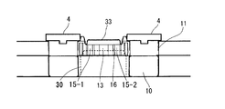
- the can body is transported by the conveyor and begins to move on the lifter of the seamer. Above the opening, the can lid positioned between the fingers on both ends of the pocket of the gas turret is transported on the circular arc track.
- the state of being positioned above the can opening is shown, and in this state, the longitudinal center of the gas flow blown out from the nozzle outlet is set to be in a state slightly below the bottom end of the can lid,
- the displacement gas flow blown out from the mouth has a depth of 1/3 or more of the height of the can neck portion 31 downward from the can opening end 32 or 3 mm or more from the can opening end toward the can body, and a gap above it.
- the height of the nozzle opening is set so as to blow out to the range where it hits the outer peripheral surface of the chuck wall 34 of the can lid located through the nozzle.
- the height h of the outlet that is, the length h in the height direction of the gas flow path
- the height h of the outlet is set to the length of the can neck when the neck is at the top of the can. Then, a range satisfying the relationship of a + b / 3 ⁇ h ⁇ a + b / 1.5 is desirable. If the length h in the height direction of the gas flow path is lower than the above range, the injection flow rate becomes high, liquid spillage is likely to occur, and the amount of outside air entrainment increases, making it difficult to improve the replacement rate.
- the can shape has the presence or absence of a neck portion and various neck shapes, and the lid shape also has various heights.
- the direction is preferably 3 mm or more from the end of the can opening, more preferably 5 mm or more.
- the upper direction of the can is 3 mm or more from the opening of the can, more preferably 8 mm or more.
- the height of the opening area of the blowout port 15 of the replacement gas nozzle is made higher than the sum of the can lid height and the length of the can neck portion, and compared with the conventional parallel nozzle.
- the injection channel area height is increased.
- the gas blown out from the blow-out port hits the chuck wall of the lid and flows into the can, the parallel flow f3 that flows parallel to the gap between the lid and the can, and the can neck portion
- the flow f3 parallel to the gap has the effect of weakening the downflow f1 and mitigating the liquid level collision of f1.
- the surrounding liquid level at the collided portion rises.
- the rise of the liquid level is reduced and liquid spillage is less likely to occur.
- the gas replacement device of the present embodiment is configured as described above, and the replacement gas flow F injected from the outlets 15a and 15b collides with the central line L at an angle of 100 ° to 130 °,
- the can is bent in the axial direction of the can body and blown into the head space in the can, and the replacement gas flow collides in the collision region including the gas flow passage side edge of the can 30, which is difficult in the conventional under cover gassing.
- the replacement gas can be blown into the head space near the gas flow path side edge portion, and the gas replacement in that portion can be effectively performed.
- FIG. 7A shows the case where the opening angle is 120 °
- FIG. 7B shows the case where the conventional nozzle opening angle is 80 °.
- the time course of the gas flow is represented by a short broken line, a long broken line and Shown in the order of solid lines.
- the gas flow blown out from the blowout port first flows into the central part as if it was a breaststroke hand, and then left and right after colliding with the opposite can wall.
- the air can be efficiently replaced with a small gas flow rate because the space for extruding air is large and the space for extrusion is wide.
- the replacement gas is filled from the outside of the head space, and the flow of the inside air is driven forward with a delay. It was found that a large amount of replacement gas was required.
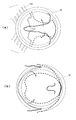
- FIG. 8 shows the result of numerical analysis of the spread after the collision in a jet colliding from two directions (a) when the collision angle is 90 ° and (b) when the collision angle is 120 °. From FIG. 8B, it can be seen that the region where the collision angle is 120 ° is wider after the collision. By increasing the angle of the impinging jet, it is considered that the region in which the replacement gas is expanded after the collision becomes wider and the replacement efficiency is increased.
- the opening height of the replacement gas channel is made higher than the conventional one as described above, but the effect of this was examined by numerical analysis as well as the influence by the opening angle.
- the result is shown in FIG.
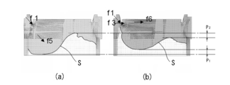
- FIG. 9 (a) shows the case where the opening height of the conventional blowing nozzle is 8 mm, and (b) shows the case where the opening height of the present invention is set to 13 mm.
- the opening height is 8 mm
- the liquid level S to which the replacement gas hits is pushed deeper by P1, compared with the case of 13 mm, and the liquid level S is raised by P2 by a corresponding amount on the downstream side. I understand that.
- the height h of the gas flow path is formed higher than 1/3 of the can lid height a and the can neck length b.
- the gas flow f1 ejected from the upper part of the nozzle opening in the replacement gas flow F hits the outer surface of the chuck wall 34 of the can lid and then enters the head space to strike the liquid surface.
- the nozzle opening area is large, the flow velocity is slowed, so that the impact of hitting the liquid surface is small, the liquid surface collision flow is weakened, and the liquid surface near the gas flow path edge is pushed up.
- the occurrence of liquid spillage in the traveling direction can be suppressed, and gas replacement in the vicinity of the liquid surface and the inner peripheral surface of the can can be performed efficiently.
- the gas flow f2 below the nozzle opening hits the outer peripheral surface of the neck 31 of the can and surrounds the vicinity with a replacement gas atmosphere, thereby preventing the outside air from being sucked into the can.
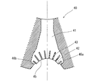
- FIG. 4 shows another embodiment of the nozzle body of the gas replacement device of the present invention.
- the nozzle body 40 of the present embodiment is different from the nozzle body shown in FIG. 1 in that the replacement gas flow path is not branched and the replacement gas outlet 42 is formed on the outer peripheral surface of the arcuate recess 45.
- the gas replacement gas outlets are radially arranged so that the replacement gas is blown into the center of the arc. Therefore, in this embodiment, the wind direction adjusting plate 43 is arrange
- An opening in the height direction higher than the sum of the height of the can lid to be replaced and the height of the can neck portion is 1/3.
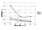
- FIG. 5 shows the amount of residual oxygen in the head space when the replacement gas flow rate is changed to 600, 800, and 1000 Nl / min
- FIG. 6 shows the change in the amount of liquid spillage.
- Comparative Example 1 As Comparative Example 1, a gas displacement device having a nozzle height of 8 mm in a nozzle body having the structure shown in FIG. 11 was employed. Other gas replacement conditions are the same as in the examples. Comparative Example 2: As Comparative Example 2, a nozzle having a structure in which a gas replacement device has a buffer in a replacement gas flow path as described in Patent Document 1 and injection ports are arranged radially is employed. Other gas replacement conditions are the same as in the examples. In Comparative Examples 1 and 2 above, the residual oxygen amount and liquid spillage in the head space were measured when the replacement gas flow rate was changed to 600, 800, and 1000 Nl / min. The above experiment was performed for each of the 6 cans in both the examples and comparative examples.
- FIG. 5 The average value of the measurement result of each residual oxygen amount for each injection flow rate is shown in FIG.
- the a diagram represents Example
- the b diagram represents Comparative Example 1
- the c diagram represents Comparative Example 2.
- FIG. 6 shows the amount of liquid spillage.
- a bar graph is displayed in FIG. 6, meaning that no liquid spill occurred in Comparative Example 2 at 800 Nl / min.
- the residual oxygen amount that is, the gas replacement rate
- the residual oxygen amount in the head space is about 0.076 ml to 0.027 ml. Halved.
- the residual oxygen amount is about 0.255 ml, and the substitution rate is remarkably bad.
- Comparative Example 3 The same gas replacement conditions as in Example 2 using a nozzle body in which the discharge angle is 100 ° and the height of the discharge port is 7 mm in the same radial comb-like nozzle shape as the nozzle body of Example 2 Thus, the amount of liquid spillage and the amount of residual oxygen when undercover gassing was performed at a replacement gas injection flow rate of 900 cc were obtained by numerical analysis. The results are shown in Table 1 together with Example 2.
- the present invention has a dramatic effect that a gas replacement rate equal to or higher than that of the conventional gas can be secured with a small replacement gas flow rate and that the liquid spillage amount is zero. .
- the replacement gas consumption can be saved by 30% or more, and a significant cost reduction can be expected.
- the present invention can be used as a gas replacement device that replaces the residual gas by blowing a replacement gas into the head space of the content-filled container.
- the replacement gas flow rate can be reduced to achieve a high replacement rate and a significant reduction in liquid spillage.
- it has high industrial applicability as an undercover gassing device for cans, but it is not limited to gas replacement for can containers, but for example, heat for gas replacement devices just before sealing bottle lids and lid materials for cup containers It can also be applied as a gas replacement device before sealing.
Landscapes
- Engineering & Computer Science (AREA)
- Mechanical Engineering (AREA)
- Chemical & Material Sciences (AREA)
- Dispersion Chemistry (AREA)
- General Engineering & Computer Science (AREA)
- Chemical Kinetics & Catalysis (AREA)
- Vacuum Packaging (AREA)
- Filling Or Discharging Of Gas Storage Vessels (AREA)
Abstract
Priority Applications (6)
| Application Number | Priority Date | Filing Date | Title |
|---|---|---|---|
| PCT/JP2010/059370 WO2011151902A1 (fr) | 2010-06-02 | 2010-06-02 | Procédé et dispositif pour remplacement de gaz de récipient |
| CN201080067183.9A CN102917953B (zh) | 2010-06-02 | 2010-06-02 | 容器的气体置换方法以及装置 |
| KR1020127033136A KR101584165B1 (ko) | 2010-06-02 | 2010-06-02 | 용기의 가스 치환 방법 및 장치 |
| US13/701,659 US10065756B2 (en) | 2010-06-02 | 2010-06-02 | Method and device for gas replacement of container |
| EP10852508.0A EP2578503B1 (fr) | 2010-06-02 | 2010-06-02 | Procédé et dispositif pour remplacement de gaz de récipient |
| JP2012518179A JP5906533B2 (ja) | 2010-06-02 | 2010-06-02 | 容器のガス置換方法及び装置 |
Applications Claiming Priority (1)
| Application Number | Priority Date | Filing Date | Title |
|---|---|---|---|
| PCT/JP2010/059370 WO2011151902A1 (fr) | 2010-06-02 | 2010-06-02 | Procédé et dispositif pour remplacement de gaz de récipient |
Publications (1)
| Publication Number | Publication Date |
|---|---|
| WO2011151902A1 true WO2011151902A1 (fr) | 2011-12-08 |
Family
ID=45066299
Family Applications (1)
| Application Number | Title | Priority Date | Filing Date |
|---|---|---|---|
| PCT/JP2010/059370 Ceased WO2011151902A1 (fr) | 2010-06-02 | 2010-06-02 | Procédé et dispositif pour remplacement de gaz de récipient |
Country Status (6)
| Country | Link |
|---|---|
| US (1) | US10065756B2 (fr) |
| EP (1) | EP2578503B1 (fr) |
| JP (1) | JP5906533B2 (fr) |
| KR (1) | KR101584165B1 (fr) |
| CN (1) | CN102917953B (fr) |
| WO (1) | WO2011151902A1 (fr) |
Cited By (2)
| Publication number | Priority date | Publication date | Assignee | Title |
|---|---|---|---|---|
| CN107922067A (zh) * | 2015-08-24 | 2018-04-17 | 三菱重工机械系统株式会社 | 气体置换系统及气体置换方法 |
| US10941029B2 (en) | 2015-08-24 | 2021-03-09 | Mitsubishi Heavy Industries Machinery Systems, Ltd. | Filling-and-sealing device and filling-and-sealing method |
Families Citing this family (3)
| Publication number | Priority date | Publication date | Assignee | Title |
|---|---|---|---|---|
| KR102102764B1 (ko) | 2018-12-27 | 2020-04-22 | 주식회사 세원정공 | 카울 크로스 부품의 성형 및 체결부 접합 겸용 금형장치 |
| IT202200006953A1 (it) * | 2022-04-07 | 2023-10-07 | Gai Macch S P A | Metodo e gruppo di accoppiamento di un coperchio ad un contenitore contenente un prodotto alimentare per la formatura di lattine |
| CA3217382A1 (fr) * | 2022-10-23 | 2024-04-23 | Bevcorp, Llc | Assemblages de tourelle pour un systeme a sceller des contenants |
Citations (6)
| Publication number | Priority date | Publication date | Assignee | Title |
|---|---|---|---|---|
| JPS4928627B1 (fr) | 1968-12-05 | 1974-07-27 | ||
| JPS57122774A (en) * | 1981-01-23 | 1982-07-30 | Toyo Seikan Kaisha Ltd | Preparation of canned juice |
| JPH08324513A (ja) | 1995-06-06 | 1996-12-10 | Mitsubishi Heavy Ind Ltd | 飲料容器内気体置換装置 |
| JP2003312609A (ja) * | 2002-04-19 | 2003-11-06 | Mitsubishi Materials Corp | 缶のガス置換装置 |
| JP2004059016A (ja) | 2002-07-25 | 2004-02-26 | Toyo Seikan Kaisha Ltd | ガス置換方法及びその装置 |
| JP2005059885A (ja) | 2003-08-12 | 2005-03-10 | Toyo Seikan Kaisha Ltd | ガス置換方法およびその装置 |
Family Cites Families (15)
| Publication number | Priority date | Publication date | Assignee | Title |
|---|---|---|---|---|
| US2184493A (en) * | 1935-11-23 | 1939-12-26 | Crown Cork & Seal Co | Filling and crowning mechanism |
| US2693305A (en) * | 1949-02-17 | 1954-11-02 | Continental Can Co | Apparatus for removing air from the head spaces of filled cans |
| US3246447A (en) * | 1963-02-25 | 1966-04-19 | Anchor Hocking Glass Corp | Air purging mechanism |
| US4409252A (en) * | 1982-04-12 | 1983-10-11 | Messer Griesheim Gmbh | Procedure for packaging of food under protective gas in synthetic containers with flexible tops |
| EP0092966B1 (fr) * | 1982-04-22 | 1987-01-28 | Daiwa Can Company, Limited | Procédé de fabrication d'un récipient fermé contenant un comestible et un gaz |
| DE3515334C2 (de) * | 1985-04-27 | 1987-04-09 | Krones Ag Hermann Kronseder Maschinenfabrik, 8402 Neutraubling | Gefäßverschließmaschine |
| FR2614005B1 (fr) * | 1987-04-15 | 1989-10-13 | Bresse Bleu Ste Laitiere Coop | Appareil pour injecter un gaz neutre dans des barquettes notamment de produits alimentaires |
| US5201165A (en) * | 1990-10-05 | 1993-04-13 | International Paper Company | Gas displacement device for packaging food and non-food products |
| US5247746A (en) * | 1992-06-04 | 1993-09-28 | W. R. Grace & Co.-Conn. | Tray sealing and gas flush apparatus |
| US5617705A (en) * | 1993-09-16 | 1997-04-08 | Sanfilippo; James J. | System and method for sealing containers |
| US5417255A (en) * | 1993-09-16 | 1995-05-23 | Sanfilippo; James J. | Gas flushing apparatus and method |
| JPH0928627A (ja) | 1995-05-13 | 1997-02-04 | Daito Syst:Kk | ブラインドの洗浄方法 |
| AU3344199A (en) * | 1998-04-17 | 1999-11-08 | Toyo Seikan Kaisha Ltd. | Method and device for manufacturing positive pressure packaging body |
| JP4429008B2 (ja) * | 2003-12-22 | 2010-03-10 | サントリーホールディングス株式会社 | ガス置換装置およびガス置換方法 |
| US20070056251A1 (en) * | 2005-01-05 | 2007-03-15 | Ruppman Kurt H Sr | Method and Apparatus for Flushing a Container with an Inert Gas |
-
2010
- 2010-06-02 EP EP10852508.0A patent/EP2578503B1/fr not_active Not-in-force
- 2010-06-02 US US13/701,659 patent/US10065756B2/en active Active
- 2010-06-02 CN CN201080067183.9A patent/CN102917953B/zh active Active
- 2010-06-02 KR KR1020127033136A patent/KR101584165B1/ko active Active
- 2010-06-02 JP JP2012518179A patent/JP5906533B2/ja active Active
- 2010-06-02 WO PCT/JP2010/059370 patent/WO2011151902A1/fr not_active Ceased
Patent Citations (6)
| Publication number | Priority date | Publication date | Assignee | Title |
|---|---|---|---|---|
| JPS4928627B1 (fr) | 1968-12-05 | 1974-07-27 | ||
| JPS57122774A (en) * | 1981-01-23 | 1982-07-30 | Toyo Seikan Kaisha Ltd | Preparation of canned juice |
| JPH08324513A (ja) | 1995-06-06 | 1996-12-10 | Mitsubishi Heavy Ind Ltd | 飲料容器内気体置換装置 |
| JP2003312609A (ja) * | 2002-04-19 | 2003-11-06 | Mitsubishi Materials Corp | 缶のガス置換装置 |
| JP2004059016A (ja) | 2002-07-25 | 2004-02-26 | Toyo Seikan Kaisha Ltd | ガス置換方法及びその装置 |
| JP2005059885A (ja) | 2003-08-12 | 2005-03-10 | Toyo Seikan Kaisha Ltd | ガス置換方法およびその装置 |
Non-Patent Citations (1)
| Title |
|---|
| See also references of EP2578503A4 * |
Cited By (4)
| Publication number | Priority date | Publication date | Assignee | Title |
|---|---|---|---|---|
| CN107922067A (zh) * | 2015-08-24 | 2018-04-17 | 三菱重工机械系统株式会社 | 气体置换系统及气体置换方法 |
| CN107922067B (zh) * | 2015-08-24 | 2020-03-13 | 三菱重工机械系统株式会社 | 气体置换系统及气体置换方法 |
| US10941029B2 (en) | 2015-08-24 | 2021-03-09 | Mitsubishi Heavy Industries Machinery Systems, Ltd. | Filling-and-sealing device and filling-and-sealing method |
| US11180357B2 (en) | 2015-08-24 | 2021-11-23 | Mitsubishi Heavy Industries Machinery Systems, Ltd. | Gas replacement system and gas replacement method |
Also Published As
| Publication number | Publication date |
|---|---|
| EP2578503B1 (fr) | 2016-03-23 |
| JPWO2011151902A1 (ja) | 2013-07-25 |
| KR101584165B1 (ko) | 2016-01-11 |
| EP2578503A4 (fr) | 2014-03-05 |
| KR20130038878A (ko) | 2013-04-18 |
| US20130078116A1 (en) | 2013-03-28 |
| US10065756B2 (en) | 2018-09-04 |
| CN102917953A (zh) | 2013-02-06 |
| EP2578503A1 (fr) | 2013-04-10 |
| JP5906533B2 (ja) | 2016-04-20 |
| CN102917953B (zh) | 2014-11-05 |
| EP2578503A8 (fr) | 2013-07-17 |
Similar Documents
| Publication | Publication Date | Title |
|---|---|---|
| JP5906533B2 (ja) | 容器のガス置換方法及び装置 | |
| CN102292265B (zh) | 容器的气体置换方法及其装置 | |
| JP5201377B1 (ja) | 充填密封方法及び装置 | |
| WO2011049505A1 (fr) | Tête de buse | |
| MX2011003341A (es) | Metodo para llenado y dispositivo. | |
| KR100816895B1 (ko) | 가스 치환 장치 및 가스 치환 방법 | |
| CN216970082U (zh) | 灌装头及其灌装装置 | |
| JP5442241B2 (ja) | 容器のガス置換方法及びその装置 | |
| CN103313929B (zh) | 液化气添加用喷嘴 | |
| JP7661056B2 (ja) | ノズル | |
| US11827399B2 (en) | Funnels for package filling | |
| JP2009073545A (ja) | 不活性ガス噴射装置 | |
| CN101180234B (zh) | 用于防止被充填的容器在输送过程中溅出的设备 | |
| JP2004262528A (ja) | 不活性ガス置換方法とその装置 | |
| JP7013815B2 (ja) | 容器処理装置および容器処理方法 | |
| JP2003312609A (ja) | 缶のガス置換装置 | |
| JP7558121B2 (ja) | 水滴除去装置および水滴除去方法 | |
| CN116923770B (zh) | 灌装头及其灌装装置和灌装方法 | |
| JP4816857B2 (ja) | 容器内残存酸素量の低減方法及びその装置 | |
| JP2003341617A (ja) | ボトル缶のガス置換装置および置換方法 |
Legal Events
| Date | Code | Title | Description |
|---|---|---|---|
| WWE | Wipo information: entry into national phase |
Ref document number: 201080067183.9 Country of ref document: CN |
|
| 121 | Ep: the epo has been informed by wipo that ep was designated in this application |
Ref document number: 10852508 Country of ref document: EP Kind code of ref document: A1 |
|
| WWE | Wipo information: entry into national phase |
Ref document number: 2012518179 Country of ref document: JP |
|
| WWE | Wipo information: entry into national phase |
Ref document number: 1201006265 Country of ref document: TH |
|
| NENP | Non-entry into the national phase |
Ref country code: DE |
|
| WWE | Wipo information: entry into national phase |
Ref document number: 13701659 Country of ref document: US |
|
| ENP | Entry into the national phase |
Ref document number: 20127033136 Country of ref document: KR Kind code of ref document: A |
|
| WWE | Wipo information: entry into national phase |
Ref document number: 2010852508 Country of ref document: EP |