WO2012002192A1 - 薬液塗工連続シート中の薬液塗工量を搬送過程で測定する方法、ティシュペーパー製品用二次原反ロールの製造設備及び薬液が塗工されたティシュペーパー製品の製造方法 - Google Patents
薬液塗工連続シート中の薬液塗工量を搬送過程で測定する方法、ティシュペーパー製品用二次原反ロールの製造設備及び薬液が塗工されたティシュペーパー製品の製造方法 Download PDFInfo
- Publication number
- WO2012002192A1 WO2012002192A1 PCT/JP2011/064104 JP2011064104W WO2012002192A1 WO 2012002192 A1 WO2012002192 A1 WO 2012002192A1 JP 2011064104 W JP2011064104 W JP 2011064104W WO 2012002192 A1 WO2012002192 A1 WO 2012002192A1
- Authority
- WO
- WIPO (PCT)
- Prior art keywords
- chemical
- continuous sheet
- coating
- tissue paper
- chemical solution
- Prior art date
- Legal status (The legal status is an assumption and is not a legal conclusion. Google has not performed a legal analysis and makes no representation as to the accuracy of the status listed.)
- Ceased
Links
Images







Classifications
-
- G—PHYSICS
- G01—MEASURING; TESTING
- G01G—WEIGHING
- G01G9/00—Methods of, or apparatus for, the determination of weight, not provided for in groups G01G1/00 - G01G7/00
- G01G9/005—Methods of, or apparatus for, the determination of weight, not provided for in groups G01G1/00 - G01G7/00 using radiations, e.g. radioactive
Definitions
- the present invention relates to a method for measuring a chemical coating amount in a chemical coating continuous sheet in a conveying process, a manufacturing equipment for a secondary raw roll for tissue paper products, and a manufacturing method for a tissue paper product coated with chemicals. It is.
- tissue paper products A bundle of tissue paper is stored in a storage box, and the tissue paper is sequentially pulled out from the outlet provided on one side of the storage box (also called a carton box or tissue carton) for use.
- Tissue paper products are well known (the type in which when one sheet is taken out, the next sheet is continuously pulled out from the take-out port is also called a pop-up type).
- These tissue paper products are coated with chemicals such as moisturizers, softeners, etc. (usually also called “lotion chemicals”) and chemicals etc.
- a tissue paper coated with a chemical is superior to a general-purpose product in terms of surface smoothness and softness.
- ⁇ Chemical solution used for chemical coating type products There are various kinds of chemicals used for chemical coating type products, but they are roughly classified into water-based chemicals containing water and polyols, and oil-based chemicals mainly containing water-insoluble wax and semi-solid at room temperature.
- Aqueous chemicals are characterized by excellent handling and low cost.
- aqueous chemicals have excellent affinity with the pulp fibers that make up the sheet when applied to the sheet, impregnate in the thickness direction of the sheet (also called the Z direction), and modify the entire sheet and its surface properties.
- the oil-based chemical liquid mainly acts to coat the surface, and acts to improve the smoothness of the surface.
- tissue paper products are as follows. First, a thin paper (also referred to as crepe paper) having a crepe is made in a papermaking facility, and the resultant is wound to produce a primary raw roll (generally also referred to as a jumbo roll). Next, the required number of primary rolls are set in a ply machine, and a primary continuous sheet is fed out from each of the set primary rolls. ) To produce a secondary raw roll comprising a laminated continuous sheet. Next, the secondary continuous sheet is sequentially fed out from the secondary roll, and the secondary continuous sheet is supplied to a folding facility called an interfolder, and the secondary continuous sheet is folded and sequentially laminated to produce a tissue paper bundle. The tissue paper bundle is stored in a storage box to obtain a tissue paper product.
- a primary raw roll generally also referred to as a jumbo roll
- a primary continuous sheet is fed out from each of the set primary rolls.
- a secondary raw roll comprising a laminated continuous sheet.
- the secondary continuous sheet is sequentially fed
- each secondary folding mechanism folds the two secondary continuous sheets, and the upstream side of the line A continuous laminated sheet bundle in which the secondary continuous sheets folded in the folding mechanism part downstream of the line are sequentially laminated on the secondary continuous sheet folded by the folding mechanism of the above, and the required number of sheets are laminated in the most downstream Is formed.
- one unit of the folding mechanism unit is a unit of equipment that folds the secondary continuous sheets so that two sheets are aligned and folded so that each sheet is folded inward, and is a unit of the mechanism unit that is the basis of the multi-stand type interfolder. .
- the rotary type interfolder folds each secondary continuous sheet fed from a pair of secondary raw rolls by a rotary folding roll while cutting from the leading end side, and cuts and folds each secondary raw roll. Sheets from the rolls are sequentially stacked to form a laminated sheet bundle. Therefore, in this rotary type interfolder, an operation for obtaining a laminated sheet bundle by appropriately marking and dividing manually at a predetermined number of laminated sheets or automatically dividing at a predetermined number of laminated sheets is required during continuous operation. . And the laminated sheet bundle obtained is a comparatively short thing of the length substantially the same as the width length of a secondary original fabric roll. For this reason, it is inferior in productivity as compared with the multi-stand type interfolder.
- a tissue paper bundle is produced at a processing speed of 100 m / min using an original roll having a width 5 times the width of the tissue paper, about 25 bundles / minute are required.
- the multi-stand type interfolder can produce 435 bundles / minute at a processing speed of 100 m / minute.
- the multi-stand type interfolder is used for manufacturing general-purpose type products that require a large amount of production. Generally, it is manufactured (for example, Patent Document 1 below).
- the rotary type interfolder is used in manufacturing a chemical coating type product is that it is possible to perform chemical coating online in addition to productivity.
- the basis weight of the chemical coating portion and the basis weight of the non-chemical coating portion of the continuous sheet were measured, and the chemical coating amount was calculated from the difference between them.
- uneven coating often occurs in the width direction of the continuous sheet (a direction orthogonal to the sheet conveyance direction (flow direction), also referred to as the CD direction). It is necessary to measure by sampling several points in the width direction of the continuous sheet, and the measurement time also takes. Thus, since the measurement of the conventional coating amount stops the operation of the equipment, the productivity deteriorates.
- the main problem of the present invention is that it is possible to quickly measure the coating amount of the aqueous chemical solution applied to the continuous sheet without stopping the flow of the continuous sheet, thereby improving the productivity in the multi-stand type interfolder.
- the purpose is to make it possible to efficiently produce a secondary material roll coated with a suitable chemical solution.
- Laminating means for laminating a primary continuous sheet fed from a plurality of primary raw rolls along the continuous direction to form a laminated continuous sheet;
- Chemical solution coating means for applying an aqueous chemical solution containing water and glycerin to the laminated continuous sheet;
- the absorbance of glycerin is measured by irradiating the chemical coating paper surface with near infrared rays, and the chemical coating is performed based on the measured absorbance of glycerin.
- a chemical coating amount measuring means for calculating the amount; Tissue comprising: a winding means for winding a chemical coating laminated continuous sheet after the chemical coating amount measuring means to form a secondary raw roll on which the chemical liquid of the tissue paper product is coated.
- a method for producing tissue paper products coated with a chemical solution In a ply machine that continuously produces a secondary roll for tissue paper products from a primary roll that has been made and wound by a papermaking facility; A lamination step in which a primary continuous sheet fed from a plurality of primary fabric rolls is laminated along the continuous direction to form a laminated continuous sheet; A chemical coating process for coating a laminated continuous sheet with an aqueous chemical containing glycerin and water; A contact embossing step for applying line-shaped contact embossing to prevent delamination on the laminated continuous sheet coated with the chemical, A slitting process for slitting a laminated continuous sheet coated with a chemical solution and subjected to contact embossing so as to have a product width of tissue paper products or a multiple of the width, Winding each slit continuous laminated sheet coaxially to form a product width of the tissue paper product or a plurality of secondary raw rolls of multiple times the width, And,
- a large number of secondary rolls coated with a chemical solution obtained by the ply machine are set corresponding to the folding mechanism part of the multi-stand type interfolder. Sending the secondary continuous sheet from the raw roll to the folding mechanism part, folding the secondary continuous sheet and obtaining the laminated band stacked while crossing the side edge of each secondary continuous sheet, Thereafter, the tissue paper bundle is cut by cutting at a predetermined interval in the flow direction, and the tissue paper bundle is stored in a storage box to obtain a tissue paper product.
- a method for producing a tissue paper product coated with a chemical solution is provided.
- the method for measuring the chemical coating amount of the present invention continuously measures the chemical coating amount of a continuous sheet conveyed in a non-contact manner using infrared spectroscopy.
- a solution containing water and glycerin is applied to a sheet mainly composed of cellulose, and in order to measure the amount of glycerin in the sheet by infrared spectroscopy, it is necessary to measure at a near infrared wavelength, but water and glycerin, The absorption wavelength of the hydroxy group of cellulose is close, and it is considered difficult to measure the amount of glycerin.
- near-infrared light having a wavelength of 1.8 ⁇ m to 2.5 ⁇ m is measured when applied to a continuous sheet, particularly a continuous sheet made of crepe paper mainly composed of cellulose.
- Absorbance peaks at a plurality of specific wavelengths are discriminated from the light transmittance curve, and an index calculated from the difference between the peak intensity of these absorbances and the absorbance peaks at the plurality of specific wavelengths of water and cellulose. Based on this, it was found that measurement can be performed with high accuracy using a calibration curve created by multivariate analysis.
- the chemical coating applied to the continuous sheet without stopping the operation of the chemical coating equipment.
- the amount of work can be continuously detected. As a result, the measurement of the chemical coating amount does not hinder the productivity of tissue paper.
- the chemical coating laminated continuous sheet and the measuring part are not in contact, the chemical coating laminated continuous sheet does not cause a physical change, and there is no influence on the product quality by measurement. It is.
- a primary raw roll JR (also referred to as a jumbo roll) is manufactured as follows using the papermaking equipment example X1 shown in FIG. To do.
- a paper stock prepared by adding an appropriate chemical to the pulp slurry from the head box 31 is supplied onto the wire 32w of the wire part 32 to form the wet paper W (forming process).
- the felt 33F of the press part 33 After being transferred to the felt 33F of the press part 33, it is sandwiched and dehydrated by the paired dewatering rolls 34 and 35 (dewatering step).
- the dried base paper S1 is wound by a winding means 38 having a winding drum 39 so that the back surface of the dried base paper S1 faces the shaft side of the primary raw roll JR (so that it becomes the winding inner surface). Take the primary roll roll JR (primary roll take-up step).
- This primary web roll JR has a diameter of 1000 to 5000 mm, a length (width) of 1500 to 9200 mm, and a winding length of 5000 to 80000 m, although it varies depending on the performance of the papermaking equipment X1.
- a calendar process may be provided on the dry base paper S1 that has been scraped off by the doctor blade 37 before the primary web winding process to smooth the front and back surfaces.
- the back surface of the dry base paper S1 means a surface opposite to the surface in contact with the cylinder of the Yankee dryer 36.
- the surface in contact with the mirror Yankee dryer is generally smoother and has better surface properties.
- the primary continuous sheet S1 constituting the primary raw roll JR is processed into the tissue paper 1 later, and has a basis weight equivalent to that of the tissue paper constituting the final product. Therefore, considering this, the primary raw sheet S1 specifically has a basis weight according to JIS P 8124 of 10 to 25 g / m 2 , preferably 12 to 20 g / m 2 , more preferably 13 to 16 g / m 2. And When the basis weight is less than 10 g / m 2 , it is preferable in terms of the softness of the tissue paper, but an appropriate strength cannot be ensured. On the other hand, if the basis weight exceeds 25 g / m 2 , the tissue paper becomes too hard and the touch is deteriorated.
- the paper thickness (measured by a dial thickness gauge manufactured by Ozaki Seisakusho) is 80 to 250 ⁇ m, preferably 100 to 200 ⁇ m, more preferably 130 to 180 ⁇ m.
- the primary continuous sheet S1 has a crepe rate of 10 to 30%, preferably 12 to 25%, more preferably 13 to 20%.
- the crepe rate is less than 10%, the paper is easy to break during subsequent processing, and the tissue paper does not stretch and has little elongation.
- the crepe rate is more than 30%, it is difficult to control the tension of the sheet at the time of processing, and it becomes easy to break the paper.
- the primary continuous sheet S1 has a dry tensile strength (hereinafter also referred to as dry paper strength) defined by JIS P 8113 of 200 to 700 cN / 25 mm, preferably 250 to 600 cN / 25 mm in 2 plies.
- the lateral direction is preferably 300 to 600 cN / 25 mm, while the transverse direction is 100 to 300 cN / 25 mm, preferably 130 to 270 cN / 25 mm, particularly preferably 150 to 250 cN / 25 mm with two plies. If the dry tensile strength of the base paper is too low, troubles such as paper breakage and elongation at the time of production and use are likely to occur, and if it is too high, the touch becomes stiff when used.
- NBKP of raw material pulp that reduces the freeness of paper stock (for example, about 30 to 40 ml) by adding a dry paper strength enhancer to the stock or wet paper.
- Known techniques such as increasing the blending ratio (for example, 50% or more) can be appropriately combined.
- dry paper strength agent starch, polyacrylamide, CMC (carboxymethyl cellulose) or a salt thereof such as sodium carboxymethyl cellulose, carboxymethyl cellulose calcium, carboxymethyl cellulose zinc and the like can be used.
- wet paper strength agent polyamide polyamine epichlorohydrin resin, urea resin, acid colloid / melamine resin, thermally crosslinkable coating PAM, and the like can be used.
- the addition amount can be about 5 to 20 kg / t by weight ratio to the pulp slurry. Further, when the dry paper strength agent is internally added, the addition amount can be about 0.5 to 1.0 kg / t in terms of the weight ratio to the pulp slurry.
- Paper the paper material used as the raw material of the primary raw material roll (primary raw material sheet) will be described.
- the paper material is obtained by adding an appropriate chemical to a slurry (pulp slurry) containing pulp as a main raw material as a fiber raw material. .
- the raw material pulp is not particularly limited, and an appropriate raw material pulp used for this type of tissue paper can be selected and used.
- Specific examples include wood pulp, non-wood pulp, synthetic pulp, and waste paper pulp. More specifically, ground wood pulp (GP), stone ground pulp (SGP), refiner ground pulp (RGP), pressurized ground wood pulp.
- PGW thermomechanical pulp
- TMP thermomechanical pulp
- CGP chemical mechanical pulp
- SCP semi-chemical pulp
- KP Kraft pulp
- LKP hardwood bleached kraft pulp
- NNKP softwood bleached kraft pulp
- CP chemical pulp
- SP soda pulp
- DP dissolved pulp
- Nylon rayon
- rayon polyester
- PVA polyvinyl alcohol
- the raw material pulp is preferably a mixture of NBKP and LBKP.
- chemicals added to the stock include dry paper strength enhancers, wet paper strength enhancers, softeners, release agents, adhesives, pH adjusters such as caustic soda, adhesives, antifoaming agents, preservatives, slime control Agents, dyes, and the like. These chemicals may be applied to the wet paper in an appropriate process.
- the primary web roll JR produced by the papermaking facility is made into a secondary chemical coating raw fabric roll at a secondary web roll production facility X2 (hereinafter also referred to as a ply machine) shown in FIG.
- the ply machine X2 can set two or more primary web rolls JR, and the primary continuous sheets (S11 and S12 in the illustrated example) fed from the primary web rolls JR and JR are laminated along the continuous direction.
- it is configured to be supplied to an overlapping portion (laminating means) 51 that is a laminated continuous sheet.
- the overlapping portion 51 is composed of a pair of nip rolls, and stacks the primary continuous sheets S11 and S12 and nips them to make the primary continuous sheets stacked and integrated.
- the surfaces of the primary continuous sheets S11 and S12 fed out from the primary raw rolls JR and JR are respectively the surfaces of the laminated continuous sheets S2 (here, the “surface” of the laminated continuous sheets is the laminated outer surface). It is supplied to the overlapping portion 51 so as to be the front and back surfaces.
- two primary web rolls JR are set and a so-called two-ply laminated continuous sheet is wound, but three sets, four sets of three-ply and four-ply laminated continuous sheets are wound. It is also possible to do so.
- chemical solution coating means 90 is provided after the overlapping portion 51 of the ply machine X2, and the chemical solution is continuously applied to the laminated continuous sheet.
- medical solution coating roll for tissue paper products means the chemical
- the measurement of the chemical coating amount is also performed by the ply machine X2, but the chemical coating step and the chemical coating amount measuring step of the present invention are performed by applying the chemical solution with equipment other than the ply machine. Needless to say, the present invention can also be applied.
- a chemical coating secondary sheet is wound by winding the chemical coating laminated continuous sheet S3 coated with the chemical at the subsequent stage.
- Winding means 56 for providing the raw roll R is provided.
- the winding means 56 has a pair of winding drums for winding the chemical coating laminated continuous sheet S3 while guiding the chemical coating laminated continuous sheet S3 to the winding means 56. These two winding drums 56A and 56A are in contact with the outer peripheral surface of the chemical solution coating secondary raw roll R and assist the winding while guiding the chemical coating laminated continuous sheet S3.
- slit means 55 is provided in the front stage of the winding unit 56, and the chemical liquid coating laminated continuous sheet S3 is slit in the continuous direction to have an appropriate width, and then the slit chemical liquid coating is performed.
- medical solution coating secondary raw roll R is made into the suitable width corresponding to a multi stand type interfolder by winding up lamination continuous sheet S3.
- the overlapping unit 51 includes a pair of nip rolls provided in a direction orthogonal to the conveying direction of the primary continuous sheets S11 and S12.
- the primary continuous sheets S11 and S12 are stacked and stacked together with a predetermined nip.
- Each primary continuous sheet is laminated and integrated with pressure.
- one or more calendar parts 52 are provided between the overlapping part 51 and the winding part 56, and the laminated continuous sheet S2 or the chemical coating laminated continuous sheet S3 can be calendered. .
- the type of calendar in the calendar unit 52 is not particularly limited, but is preferably a soft calendar or a chilled calendar for the purpose of improving the smoothness of the surface and adjusting the paper thickness.
- the soft calendar is a calendar using a roll coated with an elastic material such as urethane rubber
- the chilled calendar is a calendar made of a metal roll.
- the number of calendar parts can be changed as appropriate. If there is a plurality of installations, it has the advantage that it can be sufficiently smoothed even if the processing speed is high. On the other hand, one installation has the advantage that it can be installed even if the space is small.
- the holding angle referred to here means an angle during which the sheet is in contact with the roll as viewed from the center of the roll axis (a part of an arc of a cross section perpendicular to the axis) (hereinafter the same).
- paper making is performed as control factors such as calendar type, nip line pressure, and number of nips in calendar processing, and these control factors are preferably changed as appropriate according to the quality of tissue paper to be obtained, that is, paper thickness and surface properties.
- the processing speed is 350 to 1100 m / min, preferably 700 to 1100 m / min, more preferably 900 to 1000 m / min. If it is less than 350 m / min due to the productivity of the multi-stand type interfolder, it cannot be said that the productivity is sufficient. On the other hand, if it exceeds 1100 m / min, stable production becomes difficult.
- 700 m / min, more preferably 900 m / min is preferable from the viewpoint of increasing productivity, such as supply to a multi-stand type interfolder, sufficient stock management, and operation of a plurality of multi-stand type inter-folders. Moreover, when it is 1000 m / min or less, the stability is more excellent.
- high-speed coating means at least a speed of 350 m / min or more, usually 700 m / min or more, preferably 900 m / min or more.
- [Chemical solution coating process] In order to apply a chemical solution to the laminated continuous sheet S2 by the ply machine X2, it is desirable to employ chemical coating means 90 such as flexographic printing, spray coating, and ink jet printing. Flexographic printing is suitable because it can cope with the high speed of the ply machine, yet has flexibility such as printing plate, high speed compatibility, prevention of chemical solution scattering, and easy adjustment of coating amount. Furthermore, since the printing plate roll or the like is not brought into contact with the paper surface, it is a non-contact type coating form in which the chemical solution is directly applied to the paper surface without using the printing plate roll or the like. Spray coating and ink jet printing are desirable.
- One or a plurality of chemical coating means 90 can be installed, and in the case of installing a plurality of chemical coating means 90, they may be arranged side by side in the horizontal direction, the vertical direction, or the diagonal direction, and these installation directions including the horizontal direction are combined. It may be arranged. Since the holding angle can be reduced by arranging them in the horizontal direction, the processing speed can be increased, and when they are arranged in the vertical direction, the installation space in the horizontal direction can be reduced.
- the coating amount of the chemical solution is such that the total chemical coating amount on both sides is 0.3 to 5.0 g / m 2 , preferably 1.0 to 3.9 g / m 2 , more preferably 2.0 to 2.4 g / m 2 . If it exceeds 3.9 g / m 2 , the paper may be cut due to a decrease in paper strength or elongation, or the stickiness may be too high in quality. If it is less than 0.3 g / m 2 , the difference in quality from uncoated products such as smoothness and moistness cannot be felt. More preferably, when it is 2.0 to 2.4 g / m 2 , the sensory evaluation such as a feeling of thickness and a feeling of moistness is extremely excellent. In the present invention, the chemical coating amount may be different between the front and back surfaces.
- the viscosity of the chemical applied in the chemical coating process is preferably 1 to 700 mPa ⁇ s at 40 ° C. More preferably, it is 50 to 400 mPa ⁇ s (40 ° C.). If it is less than 1 mPa ⁇ s, the chemical solution is likely to be scattered, and conversely if it is more than 700 mPa ⁇ s, it becomes difficult to control the coating amount to be stable.
- the chemical solution used in the present invention that is, the component of the chemical solution to be measured includes water and glycerin, particularly 70 to 90% glycerin, 1 to 15% moisture, and 0.01 to 22% functional chemical. Is desirable.
- Functional agents include softeners, surfactants, inorganic and organic fine particle powders, oily components, and the like.
- Softeners and surfactants have the effect of imparting flexibility to the tissue and smoothing the surface, and anionic surfactants, cationic surfactants and zwitterionic surfactants are applied.
- Inorganic and organic fine particle powders have a smooth surface.
- the oil component has a function of improving lubricity, and higher alcohols such as liquid paraffin, cetanol, stearyl alcohol, and oleyl alcohol can be used.
- any one or more of a hydrophilic polymer gelling agent, collagen, hydrolyzed collagen, hydrolyzed keratin, hydrolyzed silk, hyaluronic acid or a salt thereof, ceramide, etc. can be arbitrarily selected as a drug that maintains the moisture retention of glycerin.
- a moisturizer such as a combination of the above can be added.
- emollients such as fragrances and various natural extracts, vitamins, emulsifiers that stabilize compounding ingredients, antifoaming agents, antifungal agents, organic acids, etc.
- An odorant can be appropriately blended.
- the temperature at the time of chemical solution coating is preferably 30 ° C. to 60 ° C., preferably 35 ° C. to 55 ° C.
- FIGS. Flexible printing
- flexographic printing uses a resin-based elastic printing plate, even if there are some irregularities of the crepe on the surface of the laminated continuous sheet S2, it can be adjusted with the printing pressure and can be applied evenly, especially 700m / Min. Or more, and even if high-speed coating is performed at 900 m / min, wrinkles are difficult to enter into the chemical coating laminated continuous sheet S3.
- one roll can handle a wide range of chemical viscosities, providing advantages in terms of management and equipment maintenance, and improving productivity.
- the number of flexographic printing plate rolls is 10 to 60 lines, preferably 15 to 40 lines, and particularly preferably 20 to 35 lines. To do. If the number of wires is less than 10, a lot of coating unevenness occurs. On the other hand, if the number of wires exceeds 60, paper dust tends to clog.
- the number of anilox rolls is 10 to 300, preferably 25 to 200, and more preferably 50 to 100. If the number of lines is less than 10, many coating irregularities occur during high-speed coating, and if the number of lines exceeds 300 lines, paper dust tends to clog.
- the anilox roll has a cell capacity of 10 to 100 cc, preferably 15 to 70 cc, particularly preferably 30 to 60 cc. If the cell capacity is less than 10 cc, a desired coating amount cannot be obtained. On the other hand, if the cell capacity is more than 100 cc, the amount of chemical solution scattered increases.
- the chemical liquid it is important that the chemical liquid can be stably applied in the chemical liquid coating process, and the number of lines of the printing plate roll and aniloc roll related to the operational stability is important.
- an appropriate method such as a doctor chamber type or a touch roll type is adopted. An example of a form employing each of these flexographic printing methods will be described in detail.
- doctor chamber format in the quillo printing is applied to the present invention
- two flexographic printing machines 91A and 91B are used to apply a chemical solution to the front and back surfaces of the laminated continuous sheet S2.
- doctor chambers 92A and 92B containing a chemical solution are arranged to face the rotatable anilox rolls 93A and 93B, and the chemical solution is transferred from the doctor chambers 92A and 92B to the anilox rolls 93A and 93B. It is supposed to be handed over.
- printing rolls 94A and 94B that are in contact with the anilox rolls 93A and 93B and are also in contact with one surface of the laminated continuous sheet S2 are rotatably installed, and a chemical solution is supplied from the anilox rolls 93A and 93B to the printing plate rolls 94A and 94B. It is supposed to be handed over. Then, while applying pressure to the laminated continuous sheet S2 with the elastic rolls 95A and 95B facing the printing plate rolls 94A and 94B with the laminated continuous sheet S2 interposed therebetween, the printing plate rolls 95A and 95B are applied to the laminated continuous sheet S2. Apply chemicals.
- Each of the doctor chambers 92A and 92B is connected to a storage tank 98 for storing the chemical liquid L via a supply hose 96 and a return hose 97, and constitutes a part of the chemical liquid circulation path (hereinafter, each printing machine 91A and 91B). For explaining the same structure, one of them may be written in parentheses as in the doctor chamber 91A (91B)).
- the storage tank 98 can be shared by the doctor chambers 92A and 92B.
- the temperature of the chemical solution is monitored and controlled in a coating device such as a paper powder or air filtration device, doctor chamber 92A or 92B contained in the chemical solution circulating in the chemical solution circulation path, and the viscosity of the chemical solution is stabilized.
- Intermediate tanks and piping heaters can be installed.
- the chemical solution is supplied from the storage tank 98 to the doctor chamber 91 ⁇ / b> A (91 ⁇ / b> B) by the supply pump 99 through the supply hose 96 by pressure supply, and the extrusion amount (flow rate) of the chemical solution is adjusted by opening / closing the adjustment valve 100.
- the return of the chemical solution from the doctor chamber 91A (91B) to the storage tank 98 is performed by the suction pump 101 via the return hose 97.
- the doctor chamber 91A (91B) includes a chamber portion 102 and blades 103 and 104 in which a chemical solution is stored.
- the chamber portion 102 is open at the end on the anilox roll 93A (93B) side, and is connected to a supply hose 96 and a return hose 97 via connecting portions 105 and 106.
- the chemical solution L is stored and supplied to the anilox roll 93A (93B).
- the blades 103 and 104 are provided so as to come into contact with the anilox roll 93A (93B), and the chemical solution L is squeezed while being pressed against the anilox roll 93A (93B), so that the chemical solution to the anilox roll 93A (93B) is drawn.
- the supply amount is constant.
- a hole 106a which is an opening portion of a predetermined diameter, is formed on the upper surface of the connection portion 106 between the return hose 97 that serves as a return path for the chemical liquid L and the chamber portion 102. Even if the chemical liquid L in the connecting portion comes into contact with the outside air through the hole 106a and the chemical liquid L is sucked by the suction pump 101, the chemical liquid L comes into contact with the outside air so that the internal pressure in the chamber portion 102 can be brought close to the external pressure. It is configured. Thereby, the internal pressure fluctuation in the doctor chamber is suppressed.
- the hole 106a may be formed so as to communicate with the upper surface of the chamber 102, for example, as long as fluctuations in the internal pressure of the chamber 102 are suppressed.
- the hole 106 a may be provided on the side surface as long as it is above the liquid level of the chemical solution L in the chamber portion 102.
- the hole 106a is provided with a discriminating means for discriminating excessive supply of the chemical liquid to the chamber unit 102.
- the discriminating means can be, for example, a transparent or translucent tube-like member 106b extending upward with the hole 106a side as the lower end, and in the process of circulating the chemical liquid L, the chemical liquid L passes through the hole in the tube. It can be visually confirmed whether or not it flows into 106b. When inflow into the tube 106b is confirmed, the amount of the chemical solution stored in the chamber portion 102 is excessive (the chemical solution L is in an oversupply state with respect to the anilox roll 91A (91B)). Can be grasped.
- the user who visually confirms the excessive state can eliminate the excessive state by, for example, adjusting the extrusion amount (flow rate) of the chemical liquid L by operating the adjustment valve 100. Since the tube 106b is hollow and the upper end side is in contact with the outside air, the operation of the hole 106a is not canceled out.
- an air filter may be installed at the upper end or the hole of the tube 106b to prevent foreign matters such as paper dust from entering.
- the oversupply state of the chemical solution L to the chamber unit 102 may be automatically determined to notify the user of the determination result.
- a sensor 106d is attached to a cylindrical portion 106c in which the peripheral edge of the hole portion 106a is extended upward, and a determination result is notified from the notification portion in response to a signal from the sensor 106d.
- the sensor 106d includes, for example, a light emitting element (not shown) that emits light toward the detected body and a light receiving element (not shown) that receives the reflected light from the detected body, and reflects the reflected light from the light receiving element. Based on the amount of received light, it is detected whether or not the height of the chemical liquid L flowing into the cylindrical portion 106c has reached the height position (y1 shown in FIG. 6) where the sensor 06d is provided.
- the notification unit 106e is a speaker or the like, and when the sensor 106d detects that the height of the chemical liquid L flowing into the cylindrical unit 106c has reached the height position where the sensor 106d is provided, The user is notified by voice.
- the user can know the fact by the notification unit 106e, and by operating the adjustment valve 100 to adjust the extrusion amount (flow rate) of the chemical liquid L, It becomes possible to eliminate the excessive state.
- an adjustment portion 106f having a needle valve structure including a needle valve and an orifice is provided in the cylindrical portion 106c. It can be configured to adjust the amount of opening of the portion of the hole 106b that comes into contact with the outside air.
- the opening amount of the hole portion 106b can be appropriately adjusted according to the internal pressure fluctuation amount in the chamber portion 102. .
- the anilox roll 93A (93B) is provided so as to contact the blades 103 and 104 of the doctor chamber 92A (92B), and the opening of the chamber portion 102 of the doctor chamber 92A (92B) is provided. It is configured such that the chemical liquid L to be supplied is adsorbed on the peripheral surface.
- the printing plate roll 94A (94B) has a cylindrical shape whose peripheral surface is made of a resin material such as a rubber material, and the peripheral surfaces (points P1 and P2 shown in FIG. 4) are anilox rolls 93A (93B) and
- the elastic roll 95A (95B) is provided so as to abut on the circumferential surface of the laminated continuous sheet S2 wound around the elastic roll 95A (95B), and is configured to be rotatable.
- the printing plate roll 94A (94B) rotates in the r2 direction when the elastic roll 95A (95B) rotates in the r1 direction, and rotates the anilox roll 93A (93B) in contact with the right end in the r1 direction.
- the printing plate roll 94A (94B) obtains the chemical solution L adsorbed on the peripheral surface of the anilox roll 93A (93B) at the point P2, conveys it to the point P1 by turning in the r2 direction, and forms the laminated continuous sheet S2. Transcript.
- the elastic roll 95A (95B) is a columnar member that is provided adjacent to the printing plate roll 94A (94B) and rotates by applying a driving force from a motor (not shown) or the like, and is laminated on the peripheral surface.
- the continuous sheet S2 is configured to be gripped. Therefore, the elastic roll 95A (95B) rotates in the r1 direction so as to wind the supplied laminated continuous sheet S2 around the peripheral surface and rotate the printing plate roll 94A (94B) and the anilox roll 93A (93B). Then, the chemical liquid L can be transferred from the printing plate roll 94A (94B) when it is conveyed to the point P1 position.
- the direction of rotation of the elastic roll 95A (95B) is the r1 direction in FIG. 4, it may of course be configured to rotate in the r2 direction.
- the anilox roll 93A (93B) and the printing plate roll 94A (94B) are rotated in directions opposite to those in FIG. 4 (that is, the anilox roll 93A (93B): r2 direction, the printing plate roll 94A (94B): r1 direction). Move.
- FIG. 8A shows a width direction D of a doctor chamber 92A (92B) in which an outer frame is formed in a wide rectangular shape along an anilox roll 93A (93B) that is formed wide and rotates around a rotation axis R0.
- a supply hose 96 is connected to a portion near the left and right ends of each, and a return hose 97 is connected to the center.
- FIG. 8B is a structural example in which three supply hoses 96 and two return hoses 97 are alternately connected at equal intervals in the width direction D.
- FIG. 8C is a structural example in which the supply hose 96 is connected to a plurality of locations near the upper side of the chamber portion 102 and the return hose 97 is connected to a plurality of locations near the lower side.
- two flexographic printing machines 91C and 91D are used to apply the chemical liquid L to the front and back surfaces of the laminated continuous sheet S2.
- dip rolls 92C and 92D which are rotatable squeezing rolls, are immersed in the chemical liquid tanks 98C and 98D containing the chemical liquid L, and the dip rolls 92C and 92D are outside the chemical liquid tanks 98C and 98D.
- the rotatable anilox rolls 93C and 93D are in contact with the rotatable anilox rolls 93C and 93D, and the amount of the chemical solution is appropriately adjusted, and the amount of the chemical solution is delivered to the anilox rolls 93C and 93D. Since the chemical solution L is transferred to the anilox rolls 93C and 93D through the dip rolls 92C and 92D, it is called a two-roll transfer system.
- the dip rolls 92C and 92D serve to take up the chemical liquid L from the chemical liquid tanks 98C and 98D and adjust the excessive chemical liquid so as not to be transferred to the anilox rolls 93C and 93D.
- the anilox rolls 93C and 93D are in contact with the printing plate rolls 94C and 94D, and the chemical solution L transferred from the dip rolls 92C and 92D is transferred to the printing plate rolls 94C and 94D.
- the printing plate rolls 94C and 94D are rotatably installed, are in contact with the anilox rolls 93C and 93D, are also in contact with one surface of the laminated continuous sheet S2, and are opposed to the elastic rolls 95C and 95D facing each other with the laminated continuous sheet S2 interposed therebetween. Then, the chemical solution L is applied to the laminated continuous sheet S2 while applying pressure to the laminated continuous sheet S2.
- a doctor blade may be provided for the anilox rolls 93C and 93D.
- the chemical solution L can be applied uniformly, and the chemical solution L is scattered from the anilox rolls 93C and 93D.
- high-speed coating has the disadvantage of increasing the frequency of care and replacement of the doctor blade.
- a spray coating apparatus can be provided so that the chemical solution is applied to the front and back surfaces of the laminated continuous sheet S2.
- a paper run is designed so that spraying is possible on the front and back surfaces of the laminated continuous sheet S2 from the side as shown in the example, and the front and back surfaces of the laminated continuous sheet S2 are sprayed from above and below.
- the form which carries out the form which designs a paper run so that it may spray on the front and back from the upper part, the form which laminates
- spray coating since the surrounding chemical liquid is likely to scatter, it is preferable to provide a hood 9F that covers the chemical coating means 90 in order to prevent the influence on other processes.
- the spray coating can adopt a nozzle spraying method, a rotor dampening spraying method, or the like.
- the types of nozzles for spraying in the nozzle type spray method include empty cone-type nozzles that spray in an annular shape, full-cone nozzles that spray in a circular shape, full-pyramid types that spray in a square shape, full-length nozzles, fan-type nozzles, etc.
- the nozzle diameter, the number of nozzles, the nozzle arrangement pattern, the number of nozzle arrangements, or the spray distance, spray pressure, spray angle, and spray so that the chemical liquid is sprayed uniformly in the width direction of the secondary continuous sheet.
- the concentration and viscosity of the liquid can be appropriately selected and used.
- the one-fluid spraying method applies pressure directly to the chemical liquid to be sprayed using compressed air and sprays mist droplets from the nozzle, or blows air into the nozzle from a fine hole opened on the side of the nozzle near the jet outlet. This is a method of sucking and spraying mist.
- the two-fluid spraying method is mixed with a liquid sprayed with compressed air inside the nozzle, an internal mixing type that atomizes, mixed with a liquid sprayed with compressed air outside the nozzle, an external mixing type that atomizes, and atomized
- Examples include a collision type system in which mist droplet particles collide with each other to further homogenize and atomize the mist droplet particles.
- the liquid to be sprayed is sent out onto a disk that rotates at high speed, and the liquid is made into fine mist by the centrifugal force of the disk.
- the amount of spray liquid (coating amount) is controlled by changing the amount of liquid delivered onto the disk.
- Rotor dampening coating device can apply a small amount of spray liquid evenly on the surface of pigment coated paper while suppressing scattering of mist droplets, and can adjust the spraying speed, mist particle size, etc. There is an advantage that is easy.
- the atomized particle diameter of the atomized chemical liquid is as small as possible.
- the spray distance, spray pressure, spray angle, spray speed in addition, in the case of the two-fluid method, the mixing ratio between the chemical liquid for spraying and the compressed air, the concentration and viscosity of the chemical liquid, etc.
- a suction device or baffle plate for removing the accompanying air, the above-mentioned
- a charging electrode electrostatic spray method
- a charging electrode is added to improve the adhesion of mist to pigment coated paper by applying high voltage to the tip of the spray nozzle and charging the mist droplet particles. May be.
- mist droplets floating as mist without being coated on the surface of the secondary continuous sheet can be sucked and collected and sprayed again.
- FIG. 11 shows a nozzle type spraying method, particularly a two-fluid type chemical spraying device 110.
- This device 110 has a chemical liquid passage 110A at the center and an air passage 110B around it, and atomizes the chemical liquid L ejected from the tip of the chemical liquid passage 110A by the air discharged from the air passage 110B.
- the chemical liquid L is sprayed in a substantially conical shape.
- 110C is an external protective casing that protects the nozzle from paper dust and the like, and allows the nozzle to be cleaned by air passing through a purge air passage if necessary.
- This type of chemical spraying device 110 can be provided at one or more intervals in the width direction of the laminated continuous sheet S2.
- the sprayed chemical solution is rebounded or the mist droplets are pushed away by the air accompanying the surface of the laminated continuous sheet, so that the mist drops are less likely to adhere to the surface of the laminated continuous sheet S2.
- the chemical solution is surrounded by the air 110G ejected from the air supply path formed in the casing 153E from the periphery of the chemical solution spraying means (spray nozzle) of the system or the two-fluid system so as to surround the sprayed chemical liquid from the chemical liquid spraying means (spray nozzle). It can apply suitably to lamination continuous sheet S2.
- FIG. 13 is an example of a rotor dampening spray device 120.
- a rotary rotor 120B is provided in a cover storage chamber 120A provided as necessary, and a chemical solution is spray-coated on the laminated continuous sheet S2 from a jet port 120C of the rotary rotor.
- curtain coater 140 An example in which the curtain coater 140 is used as the chemical solution applying means 90 in the chemical solution coating process will be described.
- the curtain coater 140 for example, a conventionally known curtain coater shown in FIG. 14 can be used.
- the curtain coater hangs the film of the chemical solution, when coating on the front and back surfaces of the laminated continuous sheet S2, the paper run is designed so that the front and back surfaces of the laminated continuous sheet S2 are positioned upward. Apply to the surface.
- the chemical liquid L prepared in advance is sent from the coating liquid storage tank to the coater head 141 by a liquid supply pump or the like.
- the inside of the coater head 141 is composed of a manifold 141a and a slit 141b, each of which is finished with high accuracy.
- the supplied chemical liquid L fills the manifold 141a and further reduces the influence of the dynamic pressure due to the liquid feed pump feeding in a narrow gap that passes when it is sent to the slit 141b, and the pressure distribution in the width direction is uniform. And flows out from the lip 142 to form a vertical curtain film 143L.
- the vertical curtain film 143L having a uniform profile in the width direction comes into contact with the continuously running laminated continuous sheet S2, and is applied to the laminated continuous sheet S2.
- the edge guide 144 does not exceed the width of the coater head 141, and further exceeds the width of the laminated continuous sheet S2, and the vertical curtain film is formed beyond the width of the laminated continuous sheet S2.
- the reason why the vertical curtain film 143L is formed to exceed the width of the laminated continuous sheet S2 is to prevent thick coating of the chemical solution L at both ends of the vertical curtain film 143L.
- the chemical liquid L flowing down beyond the width of the laminated continuous sheet S2 is collected in the liquid receiving tank 145, returned to the coating liquid storage tank, and then applied again. Further, the chemical liquid L is also collected in the liquid receiving tank 145 even when the laminated continuous sheet S2 is cut and the coating is interrupted.
- the air flow accompanying the laminated continuous sheet S2 is shielded, and the circulating air around the curtain is circulated.
- a wind shielding plate 146 is provided so that the vertical curtain film 143L reaches the laminated continuous sheet S2 without being disturbed.
- the conveying direction of the laminated continuous sheet S2 is changed by the roll 147 immediately before the coating unit, so that the influence of the air accompanying the laminated continuous sheet S2 on the coating unit is minimized. ing.
- a certain height is required from the laminated continuous sheet S2 to the outflow part at the lower part of the coater head 141.
- the height suitable for the stability is 60 to 300 mm, preferably The thickness is 100 to 250 mm, more preferably 120 to 180 mm.
- the chemical liquid coating units 130A and 130B which are of an ink jet type, have tanks 131A and 131B containing chemical liquid, and the tanks 131A and 131B can eject the chemical liquid.
- 132A and 132A are connected via a pipe. Accordingly, the chemical liquid is supplied from the tanks 131A and 131B to the inkjet heads 132A and 132B by a supply pump (not shown).
- a portion of the inkjet head 132 ⁇ / b> A (132 ⁇ / b> B) facing the laminated continuous sheet S ⁇ b> 2 that is a material to be coated has a plurality of nozzles corresponding to at least the width of the laminated continuous sheet S ⁇ b> 2.
- the nozzle plate 133A (133B) in which the holes 134 are linearly arranged is arranged.
- the ejection unit 135 includes a fluid chamber 136 that temporarily stores a chemical solution to be ejected from the nozzle hole 134, and a diaphragm that is disposed at a portion facing the nozzle plate 133A (133B) with the fluid chamber 136 interposed therebetween. 137 and a piezoelectric element 138 disposed outside the fluid chamber 136 in contact with the diaphragm 137 and formed by a piezoelectric element or the like.
- the vibration plate 138 is formed of a metal plate material such as stainless steel, and has a structure that easily transmits vibration from the piezoelectric element 138 to the fluid chamber 136.
- a control device (not shown) is connected to the piezoelectric element 68 via wiring, and a voltage is applied to the piezoelectric element 138 from the control device at a predetermined interval.
- the chemical liquid supplied from the tank 131A (131B) to the ink jet head 132A (132B) is sent into the fluid chamber 136 that exists corresponding to each nozzle hole 134, and is controlled as necessary.
- a voltage is applied to the piezoelectric element 138, the chemical solution is ejected from the nozzle holes 134 all at once, and accordingly, the chemical solution is applied over the entire width of one side of the laminated continuous sheet S3. Will be.
- the ink jet format is a structure that employs a piezo element in an on-demand manner, but a thermal jet type may be employed. Further, instead of the on-demand method, a continuous-type injection device capable of continuous injection may be employed.
- the chemical coating amount is characteristically measured by near infrared spectroscopy in the present invention. Measurement is continuously performed without stopping the conveyance of the continuous sheet S3.
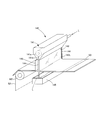
- a chemical coating amount measuring means 70 is provided after the chemical coating means 90.
- the chemical solution coating amount measuring means 70 an infrared multi-component meter manufactured by Chino Co., Ltd. or the like can be used.
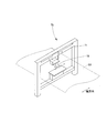
- the chemical coating amount measuring means 70 in the illustrated example has a detection unit 72 attached in a suspended manner to a frame base 71 that is bridged in the direction intersecting the transport direction on the transport path of the chemical coating laminated continuous sheet S3.
- the detection unit 72 is connected to a computer (not shown) that receives the detection data as an electrical signal and calculates the chemical application amount.
- the detection unit 72 irradiates near-infrared rays on the chemical coating surface (front and back surfaces) of the chemical coating laminated continuous sheet S3 to be conveyed and detects the absorbance of glycerin and water in the chemical. Then, in the computer, the mass of glycerin is calculated based on calibration curve data calculated in advance from the absorbance of glycerin and water detected by the detection unit 72, and the chemical solution coating amount is calculated from the mass of glycerin. The calculation of the mass of glycerin and the amount of chemical solution applied by a computer can be sufficiently performed in real time by using a known computer computer.
- the distance between the detection surface of the detection unit 72 and the paper surface of the chemical coating laminated continuous sheet S3 is 10 to 100 mm, and the measurement angle of the chemical coating laminated continuous sheet facing the detection surface is substantially parallel to the plane within 0 ° ⁇ 15 °. It is desirable that the sheet travels perpendicular to the infrared irradiation light. In other words, the measurement accuracy is increased within these ranges.
- the chemical coating amount measuring means 70 in the illustrated example is configured such that the detection unit can be moved in the width direction of the chemical coating laminated continuous sheet S3 by a known traverse mechanism as indicated by a one-dot chain line in the figure. It is configured so that the absorbance detection site on the sheet surface of the laminated continuous sheet S3 can be scanned in the width direction of the chemical liquid coating laminated continuous sheet S3.
- the detector 72 can be moved continuously or stepwise by a known motor mechanism or servo mechanism. Since coating unevenness is likely to occur in the width direction of the chemical coating laminated continuous sheet, the measurement accuracy is increased by allowing the absorbance detection site to be scanned in the width direction of the chemical coating laminated continuous sheet S3.
- interval and stop time are appropriate design matters.
- the chemical coating amount in the width direction in the chemical coating means 90 in order to correct the coating unevenness.
- the detection unit 72 is provided suspended from above the chemical coating laminated continuous sheet S3. However, the detection unit 72 is provided below the chemical coating laminated continuous sheet S3, and the chemical coating laminated from below. You may make it measure the chemical
- the absorbance is measured by applying the chemical solution to (2 plies), it is possible to determine the absorbance peak of glycerin at multiple specific wavelengths from the transmittance curve of near infrared light with a wavelength of 1.8 ⁇ m to 2.5 ⁇ m. It was found that.
- the calibration curve created by multivariate analysis can be used with sufficient accuracy and sufficient chemical coating.
- the quantity can be measured.
- contact embossing process Next, the contact embossing process will be described. As shown in FIG.2 and FIG.19, in manufacturing the chemical
- Contact embossing is preferably performed before the slitting process and after the chemical coating amount measuring process. This is because the sheet is not fluttered before the slit and there is less risk of operational trouble. In addition, if contact embossing is present, there is a possibility that the measurement of the chemical coating amount cannot be obtained accurately.
- the contact embossing means 54 for applying the contact embossing is made of metal and hard having a receiving roll 54B which is a metal roll or an elastic roll and a fine convex portion 154C on the surface.
- the rollers 54A are installed so as to be rotatable while abutting the outer peripheral surfaces with each other with a predetermined pressure.
- the contact embossed CE By applying the contact embossed CE in this way, delamination of the chemical coating laminated continuous sheet S3 formed by laminating a plurality of primary continuous sheets (S11, S12 in the illustrated example) is effectively prevented.
- the contact embossing CE is formed so as to be positioned on both sides in consideration of the width of the tissue paper, that is, in consideration of the slit width in the subsequent stage, so that the end of the tissue paper is difficult to be delaminated. desirable.
- the contact embossing means 54 When the contact embossing means 54 is applied by the contact embossing means 54, 0.3 to 2.5 seconds, preferably 0.3 to 1.0 seconds after the chemical solution is applied to the chemical solution coating laminated continuous sheet S3. It is better to apply the contact embossing CE within. If the time is less than 0.3 seconds, the chemical solution is not sufficiently absorbed by the base paper, so that the chemical solution adheres to the receiving roll 54B and the roller 54A and the paper is cut off, or dirt is attached to the receiving roll 54B and the roller 54A. When the time exceeds 2.5 seconds, the crepe of the chemical coating laminated continuous sheet S3 coated with the chemical is stretched, so that it is difficult for subsequent wrinkles to occur, and it becomes difficult to obtain a bulky tissue paper product. In addition, when the chemical coating laminated continuous sheet S3 is fully stretched, there is no stretch that can cope with draw fluctuations, and the tensile strength is reduced due to moisture absorption and water absorption.
- the means for joining is not limited to the above example, and the tip shape of the convex portion 54C may be a point, square, rectangular, circular, elliptical or the like as a roller.
- the tip shape may be an elongated linear shape, a thin linearly extending shape, or the like.
- the arrangement of the convex portions can be equally spaced, but it may not be staggered or evenly spaced, and in addition to arranging the convex portions in a row and continuously applying contact embossing, It is also conceivable to arrange the convex portions in two or more rows.
- a plurality of contact embossed groups may be applied by arranging a plurality of groups in which convex portions are arranged so that contact embossing is closely applied in a plurality of rows.
- the slit means 55 that performs the slit processing can be a slit means that includes a plurality of roll cutters and receiving portions arranged in parallel with a gap in the width of the tissue paper in the width direction of the laminated continuous sheet.
- Each laminated continuous sheet thus slit is wound up to form a secondary roll for a multi-stand type interfolder.
- a unit hereinafter also simply referred to as a roll unit) can be configured.
- the absorbance of glycerin can be detected and measured in a state where a chemical solution containing water and glycerin is applied to a thin paper, and the amount of glycerin applied can be calculated from the absorbance. Based on the analysis, it was found that it was possible to measure the amount of water-based chemical solution containing water and glycerin applied to thin paper.
- Chemical solution applying means 9F ... Hood, 91A to 91F ... Flexographic printing machine, 92A, 92B ... Doctor chamber, 92C, 92D ... Dip roll (drawing roll), 93A, 93B, 93C, 93D ... Anilox roll 94A, 94B, 94C, 94D ... printing plate roll, 95A, 95B, 95C, 95D ... elastic roll, 96 ... supply hose, 97 ... return hose, 98 ... storage tank, 98C, 98D ... chemical solution tank, 99 ... feed pump DESCRIPTION OF SYMBOLS 100 ... Adjustment valve 101 ... Suction pump 102 ... Chamber part 103, 104 ...
Landscapes
- Health & Medical Sciences (AREA)
- General Health & Medical Sciences (AREA)
- Toxicology (AREA)
- Physics & Mathematics (AREA)
- General Physics & Mathematics (AREA)
- Sanitary Thin Papers (AREA)
- Investigating Or Analysing Materials By Optical Means (AREA)
- Paper (AREA)
Abstract
【課題】ティシュペーパー製品用の薬液塗工原反ロールを製造する過程で、薬液塗工されたシートの薬液塗工量を迅速に測定する。 【解決手段】 複数の一次原反ロールから繰り出される一次連続シートをその連続方向に沿って積層して積層連続シートとする積層手段と、積層連続シートに対して薬液を塗工する薬液塗工手段と、前記薬液が塗工された連続シートを搬送する過程で、その薬液塗工紙面に近赤外線を照射して薬液中の所定成分の吸光度を測定し、その測定した所定成分の吸光度に基づいて薬液塗工量を算出する薬液塗工量測定手段と積層連続シートを巻取って二次原反ロールを形成する巻取り手段と、を有することを特徴とするティシュペーパー製品用二次原反ロールの製造設備。
Description
本発明は、薬液塗工連続シート中の薬液塗工量を搬送過程で測定する方法、ティシュペーパー製品用二次原反ロールの製造設備及び薬液が塗工されたティシュペーパー製品の製造方法に関するものである。
<ティシュペーパー製品>
複数枚のティシュペーパーからなる束が収納箱内に収納され、その収納箱(カートン箱或いはティシュカートンとも称される)の一面に設けられた取り出し口からティシュペーパーを順次一枚ずつ引き出して使用するティシュペーパー製品はよく知られる(一枚を取り出すとそれに連続して次ぎの一枚が取出し口から引き出される形式をポップアップ式ともいう)。
このティシュペーパー製品においては、収納されるティシュペーパーに保湿剤、柔軟剤、などの薬液(通常「ローション薬液」とも呼ばれる)を塗工した薬液塗工タイプのものと、薬液等が塗工されていない汎用品或いは汎用タイプのものがある。
薬液が塗工されたティシュペーパーは、表面の滑らかさや柔らかさにおいて汎用品のものよりも優れる。
薬液塗工タイプの製品は、花粉症やインフルエンザが流行する時期など洟をかむ機会が増える時期に需要が増加する傾向にあったが、近年では、表面の滑らかさや柔らかさ等の使用感における利点が評価され、季節、時期を問わずに使用されるようになってきており、その需要は拡大している。
複数枚のティシュペーパーからなる束が収納箱内に収納され、その収納箱(カートン箱或いはティシュカートンとも称される)の一面に設けられた取り出し口からティシュペーパーを順次一枚ずつ引き出して使用するティシュペーパー製品はよく知られる(一枚を取り出すとそれに連続して次ぎの一枚が取出し口から引き出される形式をポップアップ式ともいう)。
このティシュペーパー製品においては、収納されるティシュペーパーに保湿剤、柔軟剤、などの薬液(通常「ローション薬液」とも呼ばれる)を塗工した薬液塗工タイプのものと、薬液等が塗工されていない汎用品或いは汎用タイプのものがある。
薬液が塗工されたティシュペーパーは、表面の滑らかさや柔らかさにおいて汎用品のものよりも優れる。
薬液塗工タイプの製品は、花粉症やインフルエンザが流行する時期など洟をかむ機会が増える時期に需要が増加する傾向にあったが、近年では、表面の滑らかさや柔らかさ等の使用感における利点が評価され、季節、時期を問わずに使用されるようになってきており、その需要は拡大している。
<薬液塗工タイプの製品に用いられる薬液>
薬液塗工タイプの製品に用いられる薬液は種々存在するが、大きく水及びポリオールを含む水系薬液、主に非水溶性のワックス等を含み常温で半固形である油系薬液に大別される。水系薬液は取り扱い性に優れ安価であるという特徴がある。
また、水系薬液はシートに塗工した場合にシートを構成するパルプ繊維との親和性に優れ、シートの厚み方向(Z方向とも称される)に含浸し、シート全体及びその表面性を改質するように作用する。これに対して油系薬液は主にその表面をコーティングするように作用し、表面の滑らかさを向上させるように作用する。
そして、水系薬液は、シートに含浸することから塗工後にシートに塗工されたクレープを伸ばす作用が大きいが、油系薬液ではそのような作用が小さい。
この両者の特質によって製造上の問題点等の課題において異なるところがある。
そして、安価、大量生産に適しているのは水系薬液である。
薬液塗工タイプの製品に用いられる薬液は種々存在するが、大きく水及びポリオールを含む水系薬液、主に非水溶性のワックス等を含み常温で半固形である油系薬液に大別される。水系薬液は取り扱い性に優れ安価であるという特徴がある。
また、水系薬液はシートに塗工した場合にシートを構成するパルプ繊維との親和性に優れ、シートの厚み方向(Z方向とも称される)に含浸し、シート全体及びその表面性を改質するように作用する。これに対して油系薬液は主にその表面をコーティングするように作用し、表面の滑らかさを向上させるように作用する。
そして、水系薬液は、シートに含浸することから塗工後にシートに塗工されたクレープを伸ばす作用が大きいが、油系薬液ではそのような作用が小さい。
この両者の特質によって製造上の問題点等の課題において異なるところがある。
そして、安価、大量生産に適しているのは水系薬液である。
<ティシュペーパー製品の従来の製造方法の概要>
ティシュペーパー製品の製造の流れは次のとおりである。
まず、抄紙設備においてクレープを有する薄葉紙(クレープ紙とも称される)を抄造し、これを巻き取って一次原反ロール(一般にジャンボロールとも称される)を製造する。
次いで、この一次原反ロールをプライマシンに必要数セットし、セットされた各一次原反ロールから一次連続シートを繰り出すとともに、適宜重ね合わせて積層一体化し、巻き取って複数のプライ(積層された)から積層連続シートからなる二次原反ロールを製造する。
次いで、二次原反ロールから順次二次連続シートを繰り出し、この二次連続シートをインターフォルダと呼ばれる折畳み設備に供給し、二次連続シートを折畳むとともに順次積層してティシュペーパー束を製造し、このティシュペーパー束を収納箱内に収納してティシュペーパー製品とする。
ティシュペーパー製品の製造の流れは次のとおりである。
まず、抄紙設備においてクレープを有する薄葉紙(クレープ紙とも称される)を抄造し、これを巻き取って一次原反ロール(一般にジャンボロールとも称される)を製造する。
次いで、この一次原反ロールをプライマシンに必要数セットし、セットされた各一次原反ロールから一次連続シートを繰り出すとともに、適宜重ね合わせて積層一体化し、巻き取って複数のプライ(積層された)から積層連続シートからなる二次原反ロールを製造する。
次いで、二次原反ロールから順次二次連続シートを繰り出し、この二次連続シートをインターフォルダと呼ばれる折畳み設備に供給し、二次連続シートを折畳むとともに順次積層してティシュペーパー束を製造し、このティシュペーパー束を収納箱内に収納してティシュペーパー製品とする。
<ティシュペーパー製品の製造に用いられるインターフォルダの種類>
ここで、ティシュペーパー製品に用いるティシュペーパー束を製造するにあたっては、マルチスタンド式(多連式)インターフォルダ(下記特許文献4、5)とロータリー式インターフォルダ(特許文献6、7)の2種のインターフォルダが使用されている。
前者のマルチスタンド式インターフォルダは、特許文献4、5にも示されるように、折り板を有する折畳み機構部がライン流れ方向に多数(通常80~120機)並設されており、各折畳み機構部対して同時にティシュペーパーの幅と同幅にスリットした二次連続シートを2シート並べて連続的に供給すると、各折畳み機構部で二枚の二次連続シートを折り畳みが行なわれるとともに、ライン上流側の折畳み機構で折り畳まれた二次連続シートの上にそれよりもライン下流側の折畳み機構部で折り畳まれた二次連続シートが順次積層され、最下流において必要枚数が積層された連続積層シート束が形成される。ここで折畳み機構部の1機とは、二次連続シートを2シート並べ各シートを互いに内側に折り込むように折り畳む設備の単位であり、マルチスタンド式インターフォルダの基本となる機構部の単位である。
一方、ロータリー式インターフォルダは、一対の二次原反ロールから繰り出された各二次連続シートを先端側から裁断しつつ回転式の折りロールによって折り畳み、その裁断し折り畳まれた各二次原反ロールからのシートが順次重ね合わせられて積層シート束を形成する。
したがって、このロータリー式インターフォルダでは、連続操業の中で所定の積層枚数のところで適宜マーキングして手動で分割する、あるいは所定積層枚数のところで自動で分割するなどして積層シート束を得る操作を要する。しかも得られる積層シート束は、二次原反ロールの幅長とほぼ同じ長さの比較的短いものである。このためマルチスタンド式インターフォルダと比較すると生産性には劣る。
具体例を例示すれば、ロータリー式インターフォルダでは、ティシュペーパーの幅の5倍幅の原反ロールを用いて、加工速度を100m/分でティシュペーパー束を生産すると、約25束/分要しているのに対して、マルチスタンド式インターフォルダでは、加工速度を100m/分で435束/分を生産することが可能である。
このため、マルチスタンド式インターフォルダは多くの生産量が必要とされる汎用タイプの製品の製造に用いられ、汎用タイプに比して生産量が少ない薬液塗工タイプの製造はロータリー式インターフォルダにより製造されるのが一般的である(例えば、下記特許文献1)。さらに、薬液塗工タイプの製品を製造するにあたってロータリー式インターフォルダが用いられるもう一つの大きな理由は、生産性以外にオンラインで薬液塗工が可能であることがある。
しかし、上述のとおり需要拡大による生産量増加を考慮すると、薬液塗工ティシュペーパーにおいてもマルチスタンドインターフォルダでの製造が望まれる。
ここで、ティシュペーパー製品に用いるティシュペーパー束を製造するにあたっては、マルチスタンド式(多連式)インターフォルダ(下記特許文献4、5)とロータリー式インターフォルダ(特許文献6、7)の2種のインターフォルダが使用されている。
前者のマルチスタンド式インターフォルダは、特許文献4、5にも示されるように、折り板を有する折畳み機構部がライン流れ方向に多数(通常80~120機)並設されており、各折畳み機構部対して同時にティシュペーパーの幅と同幅にスリットした二次連続シートを2シート並べて連続的に供給すると、各折畳み機構部で二枚の二次連続シートを折り畳みが行なわれるとともに、ライン上流側の折畳み機構で折り畳まれた二次連続シートの上にそれよりもライン下流側の折畳み機構部で折り畳まれた二次連続シートが順次積層され、最下流において必要枚数が積層された連続積層シート束が形成される。ここで折畳み機構部の1機とは、二次連続シートを2シート並べ各シートを互いに内側に折り込むように折り畳む設備の単位であり、マルチスタンド式インターフォルダの基本となる機構部の単位である。
一方、ロータリー式インターフォルダは、一対の二次原反ロールから繰り出された各二次連続シートを先端側から裁断しつつ回転式の折りロールによって折り畳み、その裁断し折り畳まれた各二次原反ロールからのシートが順次重ね合わせられて積層シート束を形成する。
したがって、このロータリー式インターフォルダでは、連続操業の中で所定の積層枚数のところで適宜マーキングして手動で分割する、あるいは所定積層枚数のところで自動で分割するなどして積層シート束を得る操作を要する。しかも得られる積層シート束は、二次原反ロールの幅長とほぼ同じ長さの比較的短いものである。このためマルチスタンド式インターフォルダと比較すると生産性には劣る。
具体例を例示すれば、ロータリー式インターフォルダでは、ティシュペーパーの幅の5倍幅の原反ロールを用いて、加工速度を100m/分でティシュペーパー束を生産すると、約25束/分要しているのに対して、マルチスタンド式インターフォルダでは、加工速度を100m/分で435束/分を生産することが可能である。
このため、マルチスタンド式インターフォルダは多くの生産量が必要とされる汎用タイプの製品の製造に用いられ、汎用タイプに比して生産量が少ない薬液塗工タイプの製造はロータリー式インターフォルダにより製造されるのが一般的である(例えば、下記特許文献1)。さらに、薬液塗工タイプの製品を製造するにあたってロータリー式インターフォルダが用いられるもう一つの大きな理由は、生産性以外にオンラインで薬液塗工が可能であることがある。
しかし、上述のとおり需要拡大による生産量増加を考慮すると、薬液塗工ティシュペーパーにおいてもマルチスタンドインターフォルダでの製造が望まれる。
<薬液塗工タイプのティシュペーパー束をマルチスタンド式インターフォルダにより製造する場合の課題>
薬液塗工タイプ製品の生産性を向上させるべくマルチスタンド式インターフォルダを採用する場合には、オフラインで薬液が塗工された二次原反ロール(薬液塗工二次原反ロール)を製造する必要がある。すなわち、プリンタ設備等の薬液塗工設備や一次原反ロールから二次原反ロールを製造するプライマシン等の前段設備において薬液塗工を行なう必要がある。プライマシンは元来高速に可動する設備であるため、プライマシンで薬液塗工を行なうのは極めて生産性の点では有用である。
しかし、この薬液塗工については、別途の薬液塗工設備で薬液塗工を行なうにしても、プライマシンで薬液を塗工するにしても、生産性の高いマルチスタンド式インターフォルダの生産速度に見合う二次原反ロールを供給すべく、高速な薬液塗工が要求されることとなる。特に、プライマシンは元来高速に可動する設備であるため、プライマシンで薬液塗工を行なう場合には必然的に高速な薬液塗工が要求される。
他方で、薬液塗工を行なう場合、薬液粘度が温度に依存するため設備周辺気温等によって薬液塗工量が変化することや、連続シートの表面性や厚みの変化によっても塗布量が変化することなどから、品質管理上、設備トラブル防止のために塗工不良の発見、塗布量の調整のために連続シートに塗工された薬液塗工量を測定する必要がある。
そして、上述の高速生産のために高速時に、薬液を塗工する場合には、その薬液塗工量の測定も迅速・高速に精査することが必要となるが、後述の従来の薬液塗工量の測定方法は、そのような迅速・高速な塗工・生産に対応できないものである。
従って、この薬液塗工量測定が結果的に薬液塗工タイプのティシュペーパー束をマルチスタンド式インターフォルダにより生産性よく製造することを困難ならしめている。
薬液塗工タイプ製品の生産性を向上させるべくマルチスタンド式インターフォルダを採用する場合には、オフラインで薬液が塗工された二次原反ロール(薬液塗工二次原反ロール)を製造する必要がある。すなわち、プリンタ設備等の薬液塗工設備や一次原反ロールから二次原反ロールを製造するプライマシン等の前段設備において薬液塗工を行なう必要がある。プライマシンは元来高速に可動する設備であるため、プライマシンで薬液塗工を行なうのは極めて生産性の点では有用である。
しかし、この薬液塗工については、別途の薬液塗工設備で薬液塗工を行なうにしても、プライマシンで薬液を塗工するにしても、生産性の高いマルチスタンド式インターフォルダの生産速度に見合う二次原反ロールを供給すべく、高速な薬液塗工が要求されることとなる。特に、プライマシンは元来高速に可動する設備であるため、プライマシンで薬液塗工を行なう場合には必然的に高速な薬液塗工が要求される。
他方で、薬液塗工を行なう場合、薬液粘度が温度に依存するため設備周辺気温等によって薬液塗工量が変化することや、連続シートの表面性や厚みの変化によっても塗布量が変化することなどから、品質管理上、設備トラブル防止のために塗工不良の発見、塗布量の調整のために連続シートに塗工された薬液塗工量を測定する必要がある。
そして、上述の高速生産のために高速時に、薬液を塗工する場合には、その薬液塗工量の測定も迅速・高速に精査することが必要となるが、後述の従来の薬液塗工量の測定方法は、そのような迅速・高速な塗工・生産に対応できないものである。
従って、この薬液塗工量測定が結果的に薬液塗工タイプのティシュペーパー束をマルチスタンド式インターフォルダにより生産性よく製造することを困難ならしめている。
<従来の薬液塗工量の測定方法と問題点>
従来、薬液塗工不良の発見等のために薬液塗工連続シートにおける薬液塗工量を測定するには、まず、薬液塗工ユニットをもつ設備(低速可動のプリンタ等の薬液塗工設備やオンライン塗布のロータリー式インターフォルダ)で連続シートに薬液を塗布せず空通し行なって操業を停止させて一旦連続シートの流れを止め、その塗布しない連続シートの単位面積当たりの質量を測定し、その後に連続シートに薬液塗布し、再び操業を停止させて連続シートの流れを止め、塗布した直後にシートの薬液塗布した部分の単位面積当たりの質量を測定する。すなわち連続シートの薬液塗工部分の坪量と薬液非塗工部分の坪量を測定し、それらの差から薬液塗工量を算出することにより行なっていた。
また、連続シートに薬液を塗工する場合、塗工ムラは連続シートの幅方向(シートの搬送方向(流れ方向)に直交する方向、CD方向とも言われる)で発生することが多く、このため連続シートの幅方向において数点サンプリングして測定する必要があり、測定時間もかかる。
このように従来塗工量の測定は、設備の稼働を停止させるため生産性が悪化する。従来の要求されていた薬液塗工タイプの生産量、あるいは低速のロータリー式インターフォルダでの生産であれば、このような設備停止の影響は小さいが、高速設備を停止させることになればその悪影響は顕著である。
そして、例えば、プライマシンにおいて薬液塗工を行なおうとする場合には、薬液塗工工程に加えてシートの積層工程も同時に停止させることになるため、より生産性の低下を招くことになる。従って、この薬液塗工量の測定は、高速に可動し、マルチスタンド式インターフォルダへの十分な薬液塗工原反ロールの供給を可能にするプライマシンでの薬液塗工を困難ならしめているともいえる。
従来、薬液塗工不良の発見等のために薬液塗工連続シートにおける薬液塗工量を測定するには、まず、薬液塗工ユニットをもつ設備(低速可動のプリンタ等の薬液塗工設備やオンライン塗布のロータリー式インターフォルダ)で連続シートに薬液を塗布せず空通し行なって操業を停止させて一旦連続シートの流れを止め、その塗布しない連続シートの単位面積当たりの質量を測定し、その後に連続シートに薬液塗布し、再び操業を停止させて連続シートの流れを止め、塗布した直後にシートの薬液塗布した部分の単位面積当たりの質量を測定する。すなわち連続シートの薬液塗工部分の坪量と薬液非塗工部分の坪量を測定し、それらの差から薬液塗工量を算出することにより行なっていた。
また、連続シートに薬液を塗工する場合、塗工ムラは連続シートの幅方向(シートの搬送方向(流れ方向)に直交する方向、CD方向とも言われる)で発生することが多く、このため連続シートの幅方向において数点サンプリングして測定する必要があり、測定時間もかかる。
このように従来塗工量の測定は、設備の稼働を停止させるため生産性が悪化する。従来の要求されていた薬液塗工タイプの生産量、あるいは低速のロータリー式インターフォルダでの生産であれば、このような設備停止の影響は小さいが、高速設備を停止させることになればその悪影響は顕著である。
そして、例えば、プライマシンにおいて薬液塗工を行なおうとする場合には、薬液塗工工程に加えてシートの積層工程も同時に停止させることになるため、より生産性の低下を招くことになる。従って、この薬液塗工量の測定は、高速に可動し、マルチスタンド式インターフォルダへの十分な薬液塗工原反ロールの供給を可能にするプライマシンでの薬液塗工を困難ならしめているともいえる。
そこで、本発明の主たる課題は、連続シートに塗工した水系薬液の塗工量を連続シートの流れを止めることなく迅速に測定することを可能にし、もってマルチスタンド式インターフォルダでの生産性に見合う薬液が塗工された二次原反ロールを効率よく生産可能にすることにある。
上記課題を解決するための手段及びそれらの作用効果は次記のとおりである。
<請求項1記載の発明>
原反ロールから繰り出した連続シートに薬液を塗工し、さらに薬液が塗工された薬液連続シートを巻取ってティシュペーパー製品用の薬液塗工ロールを形成する過程で、その薬液連続シートの薬液塗工量を測定する方法であって、
前記薬液がグリセリン及び水を含む水系薬液であり、
前記薬液連続シートを搬送する過程で、その薬液塗工紙面に近赤外線を照射してグリセリンの吸光度を測定し、その測定したグリセリンの吸光度に基づいて薬液塗工量を算出することを特徴とする薬液塗工連続シート中の薬液塗工量を搬送過程で測定する方法。
<請求項1記載の発明>
原反ロールから繰り出した連続シートに薬液を塗工し、さらに薬液が塗工された薬液連続シートを巻取ってティシュペーパー製品用の薬液塗工ロールを形成する過程で、その薬液連続シートの薬液塗工量を測定する方法であって、
前記薬液がグリセリン及び水を含む水系薬液であり、
前記薬液連続シートを搬送する過程で、その薬液塗工紙面に近赤外線を照射してグリセリンの吸光度を測定し、その測定したグリセリンの吸光度に基づいて薬液塗工量を算出することを特徴とする薬液塗工連続シート中の薬液塗工量を搬送過程で測定する方法。
<請求項2記載の発明>
前記紙面の吸光度測定部位を連続シートの幅方向に連続的又は段階的に走査させる請求項1記載の薬液塗工連続シート中の薬液含有量を搬送過程で測定する方法。
前記紙面の吸光度測定部位を連続シートの幅方向に連続的又は段階的に走査させる請求項1記載の薬液塗工連続シート中の薬液含有量を搬送過程で測定する方法。
<請求項3記載の発明>
複数の一次原反ロールから繰り出される一次連続シートをその連続方向に沿って積層して積層連続シートとした後に、その積層連続シートに対して薬液を塗工して薬液塗工連続シートとする請求項1又は2に記載の薬液塗工連続シート中の薬液含有量を搬送過程で測定する方法。
複数の一次原反ロールから繰り出される一次連続シートをその連続方向に沿って積層して積層連続シートとした後に、その積層連続シートに対して薬液を塗工して薬液塗工連続シートとする請求項1又は2に記載の薬液塗工連続シート中の薬液含有量を搬送過程で測定する方法。
<請求項4記載の発明>
一次原反ロールから連続的にティシュペーパー製品用の複数の二次原反ロールを製造するティシュペーパー製品用二次原反ロールの製造設備において、
複数の一次原反ロールから繰り出される一次連続シートをその連続方向に沿って積層して積層連続シートとする積層手段と、
積層連続シートに対して水及びグリセリンを含む水系薬液を塗工する薬液塗工手段と、
前記薬液が塗工された薬液塗工積層連続シートを搬送する過程で、その薬液塗工紙面に近赤外線を照射してグリセリンの吸光度を測定し、その測定したグリセリンの吸光度に基づいて薬液塗工量を算出する薬液塗工量測定手段と、
薬液塗工量測定手段の後段において薬液塗工積層連続シートを巻取ってティシュペーパー製品の薬液が塗工された二
次原反ロールを形成する巻取り手段と、を有することを特徴とするティシュペーパー製品用二次原反ロールの製造設備。
一次原反ロールから連続的にティシュペーパー製品用の複数の二次原反ロールを製造するティシュペーパー製品用二次原反ロールの製造設備において、
複数の一次原反ロールから繰り出される一次連続シートをその連続方向に沿って積層して積層連続シートとする積層手段と、
積層連続シートに対して水及びグリセリンを含む水系薬液を塗工する薬液塗工手段と、
前記薬液が塗工された薬液塗工積層連続シートを搬送する過程で、その薬液塗工紙面に近赤外線を照射してグリセリンの吸光度を測定し、その測定したグリセリンの吸光度に基づいて薬液塗工量を算出する薬液塗工量測定手段と、
薬液塗工量測定手段の後段において薬液塗工積層連続シートを巻取ってティシュペーパー製品の薬液が塗工された二
次原反ロールを形成する巻取り手段と、を有することを特徴とするティシュペーパー製品用二次原反ロールの製造設備。
<請求項5記載の発明>
薬液塗工量測定手段の後段において積層連続シートをティシュペーパー製品の製品幅又はその複数倍幅となるようにスリットするスリット手段を有する請求項4記載のティシュペーパー製品用二次原反ロールの製造設備。
薬液塗工量測定手段の後段において積層連続シートをティシュペーパー製品の製品幅又はその複数倍幅となるようにスリットするスリット手段を有する請求項4記載のティシュペーパー製品用二次原反ロールの製造設備。
<請求項6記載の発明>
前記薬液塗工手段は、吸光度を検出する紙面に対面する検出部が、連続シートの幅方向に連続的又は段階的に移動可能とされている請求項4記載のティシュペーパー製品用二次原反ロールの製造設備。
前記薬液塗工手段は、吸光度を検出する紙面に対面する検出部が、連続シートの幅方向に連続的又は段階的に移動可能とされている請求項4記載のティシュペーパー製品用二次原反ロールの製造設備。
<請求項7記載の発明>
薬液塗工量測定手段の後段において薬液塗工積層連続シートをティシュペーパー製品の製品幅又はその複数倍幅となるようにスリットするスリット手段を有し、
前記巻き取り手段が、スリット手段でティシュペーパー製品の製品幅又はその複数倍幅にスリットされた薬液塗工連続シートを同軸で巻取るものである請求項4記載のティシュペーパー製品用二次原反ロールの製造設備。
<請求項8記載の発明>
薬液が塗布されたティシュペーパー製品の製造方法であって、
抄紙設備により抄造され巻き取られた一次原反ロールから連続的にティシュペーパー製品用の二次原反ロールを製造するプライマシンにおいて;
複数の一次原反ロールから繰り出される一次連続シートをその連続方向に沿って積層して積層連続シートとする積層工程と、
積層連続シートに対してグリセリン及び水を含む水系の薬液を塗工する薬液塗工工程と、
薬液が塗工された積層連続シートに対して層間剥離を防止するライン状のコンタクトエンボスを施すコンタクトエンボス工程と、
薬液が塗工されコンタクトエンボスが施された積層連続シートをティシュペーパー製品の製品幅又はその複数倍幅となるようにスリットするスリット工程と、
スリットされた各積層連続シートを同軸で巻取ってティシュペーパー製品の製品幅又はその複数倍幅の複数の二次原反ロールを形成する巻取り工程とを行い、
かつ、前記薬液が塗工された連続シートを搬送する過程で、その薬液塗工紙面に近赤外線を照射してグリセリンの吸光度を測定し、その測定したグリセリンの吸光度に基づいて薬液塗工量を算出し;
前記プライマシンにより得られた、薬液が塗工された二次原反ロールを、マルチスタンド式インターフォルダの折畳機構部に対応して多数セットし、前記マルチスタンド式インターフォルダにおいて、各二次原反ロールからの二次連続シートを前記折畳機構部にそれぞれ送り込み、二次連続シートを折り畳み各二次連続シートの側端部を掛け合わせしながら積み重ねられた積層帯を得て、
その後に流れ方向に所定の間隔をおいて裁断してティシュペーパー束とし、そのティシュペーパー束を収納箱に収納してティシュペーパー製品を得る、
ことを特徴とする、薬液が塗工されたティシュペーパー製品の製造方法。
薬液塗工量測定手段の後段において薬液塗工積層連続シートをティシュペーパー製品の製品幅又はその複数倍幅となるようにスリットするスリット手段を有し、
前記巻き取り手段が、スリット手段でティシュペーパー製品の製品幅又はその複数倍幅にスリットされた薬液塗工連続シートを同軸で巻取るものである請求項4記載のティシュペーパー製品用二次原反ロールの製造設備。
<請求項8記載の発明>
薬液が塗布されたティシュペーパー製品の製造方法であって、
抄紙設備により抄造され巻き取られた一次原反ロールから連続的にティシュペーパー製品用の二次原反ロールを製造するプライマシンにおいて;
複数の一次原反ロールから繰り出される一次連続シートをその連続方向に沿って積層して積層連続シートとする積層工程と、
積層連続シートに対してグリセリン及び水を含む水系の薬液を塗工する薬液塗工工程と、
薬液が塗工された積層連続シートに対して層間剥離を防止するライン状のコンタクトエンボスを施すコンタクトエンボス工程と、
薬液が塗工されコンタクトエンボスが施された積層連続シートをティシュペーパー製品の製品幅又はその複数倍幅となるようにスリットするスリット工程と、
スリットされた各積層連続シートを同軸で巻取ってティシュペーパー製品の製品幅又はその複数倍幅の複数の二次原反ロールを形成する巻取り工程とを行い、
かつ、前記薬液が塗工された連続シートを搬送する過程で、その薬液塗工紙面に近赤外線を照射してグリセリンの吸光度を測定し、その測定したグリセリンの吸光度に基づいて薬液塗工量を算出し;
前記プライマシンにより得られた、薬液が塗工された二次原反ロールを、マルチスタンド式インターフォルダの折畳機構部に対応して多数セットし、前記マルチスタンド式インターフォルダにおいて、各二次原反ロールからの二次連続シートを前記折畳機構部にそれぞれ送り込み、二次連続シートを折り畳み各二次連続シートの側端部を掛け合わせしながら積み重ねられた積層帯を得て、
その後に流れ方向に所定の間隔をおいて裁断してティシュペーパー束とし、そのティシュペーパー束を収納箱に収納してティシュペーパー製品を得る、
ことを特徴とする、薬液が塗工されたティシュペーパー製品の製造方法。
本発明の薬液塗工量の測定方法は、赤外分光法を用いて非接触で搬送される連続シートの薬液塗工量を連続的に測定する。水及びグリセリンを含む溶液を、セルロースを主成分とするシートに塗布し、そのシート内のグリセリン量を赤外分光法で測定するには近赤外域波長での測定が必要だが、水とグリセリン、セルロースのヒドロキシ基の吸収波長が近くグリセリン量の測定は困難であると考えられおり、また従来その必要性もなかったため調査がされていなかった。しかし、本発明者らの鋭意研究の結果、連続シート、特にセルロースを主原料とするクレープ紙からなる連続シートに塗工して測定した場合において、波長1.8μm~2.5μmの近赤外光の透過率曲線から複数の特定波長での吸光度のピークが判別され、それらの吸光度のピーク強度と水およびセルロースの前記の複数の特定波長での吸光度のピークとの差異から計算される指標に基き、多変量解析により作成される検量線によって精度よく測定可能であることが知見された。
したがって、本発明に基づき赤外線分光法によりグリセリンの吸光度を測定し連続シートに塗工された薬液塗工量を測定すると、薬液塗工設備の運転を止めることなく連続シートに塗工された薬液塗工量を連続的に検出可能となる。これにより薬液塗工量の測定がティシュペーパーの生産性の阻害となることがなくなる。
また、特に700m/分の高速で搬送される連続シートに対しても、その流れる薬液塗工連続シートを測定しても極めて精度よく測定可能であり、これにより、プライマシン等の高速設備における迅速・高速かつ高品質な薬液塗工が可能となる。よって、マルチスタンド式インターフォルダに対応可能な薬液塗工二次原反ロールの生産が可能になる。
また、薬液塗工積層連続シートと測定部とが非接触であることから、薬液塗工積層連続シートに物性的な変化をもたらさず、測定による製品品質への影響がない点も本発明の効果である。
以下、本発明の実施形態について図面を参照しながら詳説する。ここでは、本発明にかかるティシュペーパー製品用の薬液塗工二次原反ロールの製造方法を説明しつつ、本発明の薬液塗工連続シート中の薬液塗工量を搬送過程で測定する方法と、ティシュペーパー製品用二次原反ロールの製造設備を説明する。なお、本発明がこの実施形態に限定されるわけではない。
<一次原反ロールの製造方法及び製造設備〔抄紙工程〕>
本発明にかかる薬液塗工二次原反ロールを製造するには、まず、図1に示す抄紙設備例X1により、一次原反ロールJR(ジャンボロールとも称される)を以下のようにして製造する。
まず、ヘッドボックス31からパルプスラリーに適宜の薬品を添加して予め調整した紙料をワイヤーパート32のワイヤ32w上に供給して湿紙Wを形成し(フォーミング工程)、次にこの湿紙Wをプレスパート33のフェルト33Fに移送したにのち対をなす脱水ロール34,35によって挟持して脱水する(脱水工程)。
本発明にかかる薬液塗工二次原反ロールを製造するには、まず、図1に示す抄紙設備例X1により、一次原反ロールJR(ジャンボロールとも称される)を以下のようにして製造する。
まず、ヘッドボックス31からパルプスラリーに適宜の薬品を添加して予め調整した紙料をワイヤーパート32のワイヤ32w上に供給して湿紙Wを形成し(フォーミング工程)、次にこの湿紙Wをプレスパート33のフェルト33Fに移送したにのち対をなす脱水ロール34,35によって挟持して脱水する(脱水工程)。
次いで、脱水された湿紙をヤンキードライヤー36の表面に付着させて乾燥させた後にドクターブレード37によって掻き剥がしてクレープを有する乾燥原紙S1(後述の一次連続シート)とする(乾燥工程)。
そして、この乾燥原紙S1をワインディングドラム39を有する巻取り手段38によって、前記乾燥原紙S1の裏面が一次原反ロールJRの軸側に対向するようして(巻き取り内面となるようにして)巻き取り、一次原反ロールJRとする(一次原反巻取り工程)。
この一次原反ロールJRは、抄紙設備X1の性能によっても相違するが、概ね直径が1000~5000mm、長さ(幅)が1500~9200mm、巻き長さが5000~80000mである。
なお、一次原反巻き取り工程の前段にドクターブレード37により掻き剥がした乾燥原紙S1に対してカレンダー工程(図示せず)を設け表裏面の平滑化処理をしてもよい。
ここで、乾燥原紙S1の裏面とは、ヤンキードライヤー36のシリンダと接していた面の反対側の面のことを意味する。なお、カレンダー工程の有無にもよるが一般には鏡面のヤンキードライヤーに接していた表面のほうが滑らかで表面性に優れる。
ここで、一次原反ロールJRを構成する一次連続シートS1は、後にティシュペーパー1に加工されるものであり、最終製品を構成するティシュペーパーと同等の坪量となる。従って、これを考慮して一次原反シートS1は具体的にはJIS P 8124による坪量が、10~25g/m2、好ましくは12~20g/m2、より好ましくは13~16g/m2とする。坪量が10g/m2未満であると、ティシュペーパーの柔らかさの点においては好ましいが、適正な強度を確保することができなくなる。他方、坪量が25g/m2を超えると、ティシュペーパーが硬くなりすぎて、肌触りが悪化する。また、紙厚(尾崎製作所製ダイヤルシックネスゲージにより測定)は80~250μm、好ましくは100~200μm、より好ましくは130~180μmとするのが望ましい。
また、一次連続シートS1は、クレープ率が10~30%、好ましくは12~25%、より好ましくは13~20%である。クレープ率が10%未満であると、後段の加工時に断紙しやすいとともに伸びの少ないコシのないティシュペーパーとなる。他方、クレープ率が30%超過であると、加工時のシートの張力コントロールが難しく断紙しやすくなり、また、製造後にはシワが発生して見栄えの悪いティシュペーパーとなりやすくなる。
また、一次連続シートS1は、JIS P 8113に規定される乾燥引張強度(以下、乾燥紙力ともいう)の縦方向が、2プライで200~700cN/25mm、好ましくは250~600cN/25mm、特に好ましくは300~600cN/25mmとされ、他方、横方向が、2プライで100~300cN/25mm、好ましくは130~270cN/25mm、特に好ましくは150~250cN/25mmとされる。原紙の乾燥引張強度が低すぎると、製造時及び使用時の断紙や伸び等のトラブルが発生し易くなり、高過ぎると使用時にごわごわした肌触りとなる。
これらの紙力は公知の方法により調整でき、例えば、乾燥紙力増強剤を紙料或いは湿紙に内添する、紙料のフリーネスを低下(例えば30~40ml程度低下)させる、原料パルプのNBKP配合率を増加(例えば50%以上に)する等の既知の手法を適宜組み合わせることができる。
なお、乾燥紙力剤としては、澱粉、ポリアクリルアミド、CMC(カルボキシメチルセルロース)若しくはその塩であるカルボキシメチルセルロースナトリウム、カルボキシメチルセルロースカルシウム、カルボキシメチルセルロース亜鉛等を用いることができる。湿潤紙力剤としては、ポリアミドポリアミンエピクロルヒドリン樹脂、尿素樹脂、酸コロイド・メラミン樹脂、熱架橋性塗工PAM等を用いることができる。
湿潤紙力剤を内添する場合、その添加量はパルプスラリーに対する重量比で5~20kg/t程度とすることができる。また、乾燥紙力剤を内添する場合、その添加量はパルプスラリーに対する重量比で0.5~1.0kg/t程度とすることができる。
[紙料]
ここで、一次原反ロール(一次原反シート)の原料となる紙料について説明すると、紙料は繊維原料としてパルプを主原料とするスラリー(パルプスラリー)に適宜の薬品を添加したものである。
ここで、一次原反ロール(一次原反シート)の原料となる紙料について説明すると、紙料は繊維原料としてパルプを主原料とするスラリー(パルプスラリー)に適宜の薬品を添加したものである。
本発明においては、原料パルプは特に限定されず、この種のティシュペーパーに用いられる適宜の原料パルプを選択して使用することができる。具体例としては、木材パルプ、非木材パルプ、合成パルプ、古紙パルプなどから、より具体的には、砕木パルプ(GP)、ストーングランドパルプ(SGP)、リファイナーグランドパルプ(RGP)、加圧式砕木パルプ(PGW)、サーモメカニカルパルプ(TMP)、ケミサーモメカニカルパルプ(CTMP)、ブリーチケミサーモメカニカルパルプ(BCTMP)等の機械パルプ(MP)、化学的機械パルプ(CGP)、半化学的パルプ(SCP)、広葉樹晒クラフトパルプ(LBKP)、針葉樹晒クラフトパルプ(NBKP)等のクラフトパルプ(KP)、ソーダパルプ(AP)、サルファイトパルプ(SP)、溶解パルプ(DP)等の化学的パルプ(CP)、ナイロン、レーヨン、ポリエステル、ポリビニルアルコール(PVA)等を原料とする合成パルプ、脱墨パルプ(DIP)、ウエストパルプ(WP)等の古紙パルプ、かすパルプ(TP)、木綿、アマ、麻、黄麻、マニラ麻、ラミー等を原料とするぼろパルプ、わらパルプ、エスパルトパルプ、バガスパルプ、竹パルプ、ケナフパルプ等の茎稈パルプ、靭皮パルプ等の補助パルプなどから、一種又は数種を適宜選択して使用することができる。
なかでも原料パルプは、NBKPとLBKPとを配合したものが好ましい。適宜古紙パルプが配合されていてもよいが、ローション薬液との相性がよく、塗工後に折り畳む本発明の製造方法において望ましく、また得られるティシュペーパーの風合いの点でも望ましいことから、バージンパルプのNBKPとLBKPのみから構成されているのがよく、その場合の配合割合(JIS P 8120)としては、NBKP:LBKP=20:80~80:20がよく、特に、NBKP:LBKP=30:70~60:40が望ましい。
紙料に添加する薬品例としては、乾燥紙力増強剤、湿潤紙力増強剤、柔軟剤、剥離剤、接着剤、苛性ソーダ等のpH調整剤、粘剤、消泡剤、防腐剤、スライムコントロール剤、染料、などが挙げられる、なお、これらの薬品は、適宜の工程で湿紙に塗工してもよい。
<二次薬液塗工原反ロールの製造方法及び製造設備>
抄紙設備で製造された一次原反ロールJRは、図2に示す二次原反ロールの製造設備X2(以下、プライマシンともいう)にて二次薬液塗工原反ロールにする。
抄紙設備で製造された一次原反ロールJRは、図2に示す二次原反ロールの製造設備X2(以下、プライマシンともいう)にて二次薬液塗工原反ロールにする。
プライマシンX2は、一次原反ロールJRを2つ以上セット可能であり、各一次原反ロールJR,JRから繰り出した一次連続シート(図示例ではS11、S12)は、その連続方向に沿って積層して積層連続シートとする重ね合わせ部(積層手段)51に供給されるように構成されている。ここで重ね合わせ部51は一対のニップロールで構成され、各一次連続シートS11,S12を積層するとともにニップして各一次連続シートを積層一体化ならしめる。
なお、図示例では、各一次原反ロールJR,JRから繰り出される一次連続シートS11,S12の表面が、それぞれ積層連続シートS2の表面(ここで積層連続シートの「表面」とは積層外面である表裏面のことである)となるようして重ね合わせ部51に供給されるようになっている。一次連続シートS11,S12の裏面がそれぞれ積層連続シートS2の表面となるよう構成してもよいし、一次連続シートS11,S12のどちらか一方の裏面が積層連続シートS2の表面となり、他方の表面が積層連続シートS2の表面となるようしてもよいが、一次原反シートS11,S12の表面は、乾燥時にヤンキードライヤーの表面に接していることから裏面と比較して毛羽立ちが少なく滑らかで肌触りが良いので、一次連続シート(乾燥原紙S1)の表面が積層連続シートS2の表裏面を構成するようにするのが望ましい。
また、本実施例では一次原反ロールJRを2つセットしていわゆる2プライの積層連続シートを巻取る例であるが、3セット、4セットとして3プライ、4プライの積層連続シートを巻取るようにすることも可能である。
本発明ではプライマシンX2の重ね合わせ部51の後段に薬液塗工手段90を有し、積層連続シートに対して連続的に薬液を塗工する。
なお、本実施形態においてはプライマシンX2にて薬液を塗工する例を示すことから、ティシュペーパー製品用の薬液塗工ロールは、薬液塗工二次原反ロールを意味することになる。合わせて薬液塗工量の測定も、このプライマシンX2にて行なう例を示すが、本発明の薬液塗工工程及び薬液塗工量の測定工程は、プライマシン以外の設備にて薬液を塗工する場合においても適用可能であることはいうまでもない。
薬液塗工手段90の後段には、本発明にかかる薬液塗工量測定手段70があり、さらにその後段に薬液が塗工された薬液塗工積層連続シートS3を巻取って薬液塗工二次原反ロールRとするための巻取り手段56が設けられている。この巻取り手段56は、薬液塗工積層連続シートS3を巻き取り手段56に案内しつつ巻取るための一対のワインディングドラムを有している。これら2つのワインディングドラム56A,56Aが薬液塗工二次原反ロールRの外周面に接して薬液塗工積層連続シートS3を案内しつつ巻き取りを補助する。
ここで、プライマシンX2においては巻き取り部56の前段にスリット手段55を設けて、薬液塗工積層連続シートS3を連続方向にスリットして適宜の幅とした後に、それらスリットされた薬液塗工積層連続シートS3を巻取ることで薬液塗工二次原反ロールRの幅をマルチスタンド式インターフォルダに対応する適宜の幅にする。
本実施の形態におけるプライマシンX2においてされる種々の加工及び手段の詳細について以下、さらに説明する。
[重ね合わせ部〔積層手段〕]
重ね合わせ部51は、上述のとおり一次連続シートS11、S12の搬送方向に直行する方向に設けられた一対のニップロールで構成され、各一次連続シートS11,S12を重ね合わせて積層するとともに所定のニップ圧をもって各一次連続シートを積層一体化ならしめる。
[重ね合わせ部〔積層手段〕]
重ね合わせ部51は、上述のとおり一次連続シートS11、S12の搬送方向に直行する方向に設けられた一対のニップロールで構成され、各一次連続シートS11,S12を重ね合わせて積層するとともに所定のニップ圧をもって各一次連続シートを積層一体化ならしめる。
[カレンダー加工]
他方、プライマシンX2においては、重ね合わせ部51から巻き取り部56までの間にカレンダー部52を一つ以上設けて積層連続シートS2、あるいは薬液塗工積層連続シートS3をカレンダー加工することができる。
他方、プライマシンX2においては、重ね合わせ部51から巻き取り部56までの間にカレンダー部52を一つ以上設けて積層連続シートS2、あるいは薬液塗工積層連続シートS3をカレンダー加工することができる。
カレンダー部52におけるカレンダーの種別は、特に限定されないが、表面の平滑性向上と紙厚の調整の理由からソフトカレンダー又はチルドカレンダーとすることが好ましい。ソフトカレンダーとは、ウレタンゴム等の弾性材を被覆したロールを用いたカレンダーであり、チルドカレンダーとは金属ロールからなるカレンダーのことである。
カレンダー部の数は、適宜変更することができる。複数設置すれば加工速度が速くとも十分に平滑化できるという利点を有する一方、一つであるとスペースが狭くとも設置可能であるという利点を有する。
二つ以上のカレンダー部を設置する場合、水平方向、上下方向、或いは斜め方向に並設することができ、また、これらの設置方向を組み合わせて配置することができる。水平方向に並設すると、抱き角度を小さくなるため加工速度が高速とすることができ、上下方向に並設すると設置スペースを小さくすることができる。なお、ここで言う抱き角度とはロールの軸中心から見てシートが接している間(軸と直行する断面の円弧の一部)の角度を意味する(以下同じ)。
カレンダー加工におけるカレンダー種別、ニップ線圧、ニップ数なども制御要因として抄紙を行うようにし、これらの制御要因は、求めるティシュペーパーの品質すなわち紙厚や表面性によって適宜変更することが好ましい。
本実施形態に係る薬液二次原反ロールRの製造設備X2又は製造方法においては、加工速度は350~1100m/分、好ましくは700~1100m/分、より好ましくは900~1000m/分である。マルチスタンド式インターフォルダの生産性との関係により350m/分未満だと十分な生産性とは言えない。他方、1100m/分超過であると安定的に生産するのが困難となる。特に700m/分、より好ましく900m/分であるとマルチスタンド式インタフォルダへの供給、十分なストック管理、さらに複数のマルチスタンド式インターフォルダの運用が可能になるなど生産性を高めるうえで好ましい。また、1000m/分以下とすると安定性がより優れる。
なお、本発明の趣旨から高速塗工とは、少なくとも速度は350m/分以上、通常は700m/分以上、好ましくは900m/分以上を意味する。
[薬液塗工工程]
プライマシンX2にて積層連続シートS2に対して薬液を塗工するには、フレキソ印刷、スプレー塗工、インクジェット印刷等の薬液塗工手段90を採用するのが望ましい。プライマシンの高速性に対応でき、しかも刷版の柔軟性、高速対応性、薬液の飛散防止、塗工量の調整が容易である等の要件からフレキソ印刷が適する。さらに、紙面に刷版ロール等を接触させないことから紙厚の低下を招かないという点では、刷版ロール等を用いず直接的に薬液を紙面に塗工する非接触形の塗工形態であるスプレー塗工、インクジェット印刷が望ましい。
プライマシンX2にて積層連続シートS2に対して薬液を塗工するには、フレキソ印刷、スプレー塗工、インクジェット印刷等の薬液塗工手段90を採用するのが望ましい。プライマシンの高速性に対応でき、しかも刷版の柔軟性、高速対応性、薬液の飛散防止、塗工量の調整が容易である等の要件からフレキソ印刷が適する。さらに、紙面に刷版ロール等を接触させないことから紙厚の低下を招かないという点では、刷版ロール等を用いず直接的に薬液を紙面に塗工する非接触形の塗工形態であるスプレー塗工、インクジェット印刷が望ましい。
薬液塗工手段90は、単数或いは複数設置することができ、複数設置する場合、水平方向、上下方向、或いは斜め方向に並設しても良く、水平方向を含めたこれらの設置方向を組み合わせて配置しても良い。水平方向に並設すると抱き角度を小さくすることができるため、加工速度を高速とすることができ、上下方向に並設すると水平方向における設置スペースを小さくすることができる。
薬液の塗工量は、両面の合計の薬液塗工量は、0.3~5.0g/m2とされ、好ましくは1.0~3.9g/m2、より好ましくは2.0~2.4g/m2とされる。3.9g/m2超過であると、紙力低下や伸びなどにより断紙したり、品質的にべたつき感が過ぎる場合も出てくる。0.3g/m2未満であると滑らかさやしっとり感など未塗工品との品質差を感じられなくなってしまう。より好ましく、2.0~2.4g/m2とすると厚み感、しっとり感といった官能評価において極めて優れたものとなる。
なお、本発明においては、表裏面において薬液塗工量が異なるようにしてもよい。
なお、本発明においては、表裏面において薬液塗工量が異なるようにしてもよい。
薬液塗工工程で塗工する薬液については、粘度は40℃で1~700mPa・sが望ましい。より好ましくは50~400mPa・s(40℃)である。1mPa・sより小さいと薬液が飛散しやすくなり、逆に700mPa・sより大きいと安定した塗工量とするコントロールがしにくくなる。
本発明に用いる薬液、すなわち測定の対象となる薬液の成分は、水及びグリセリンを含み、特にグリセリンを70~90%、水分を1~15%、機能性薬品を0.01~22%含むものであるのが望ましい。
機能性薬剤としては、柔軟剤、界面活性剤、無機および有機の微粒子粉体、油性成分などがある。柔軟剤、界面活性剤はティシューに柔軟性を与えたり表面を滑らかにしたりする効果があり、アニオン性界面活性剤、カチオン性界面活性剤及び両性イオン界面活性剤を適用する。無機および有機の微粒子粉体は表面を滑らかな肌触りとする。油性成分は滑性を高める働きがあり、流動パラフィン、セタノール、ステアリルアルコール、オレイルアルコール等の高級アルコールを用いることができる。
また機能性薬剤としてグリセリンの保湿性を維持させる薬剤として親水性高分子ゲル化剤、コラーゲン、加水分解コラーゲン、加水分解ケラチン、加水分解シルク、ヒアルロン酸若しくはその塩、セラミド等の1種以上を任意の組合せ等の保湿剤を加えることができる。
また機能性薬剤として香料、各種天然エキス等のエモリエント剤、ビタミン類、配合成分を安定させる乳化剤、薬液の発泡を抑え塗工を安定させるための消泡剤、防黴剤、有機酸などの消臭剤を適宜配合することができる。さらには、ビタミンC、ビタミンEの抗酸化剤を含有させてもよい。
薬液塗工時の温度は30℃~60℃、好ましくは35℃~55℃とすることが好ましい。
薬液塗工時の温度は30℃~60℃、好ましくは35℃~55℃とすることが好ましい。
(フレキソ印刷)
薬液塗工手段90としてフレキソ印刷機を用いた例は図3~9に示す。フレキソ印刷は樹脂性の弾力性がある刷版を用いるため積層連続シートS2の表面にクレープの多少の凹凸があっても印圧で調整可でありムラのない塗工が可能であり、特に700m/分以上、更に900m/分の高速塗工を行なっても薬液塗工積層連続シートS3にシワが入り難くなる。また、一つのロールで幅広い薬液の粘度に対応でき、管理、設備メンテナンスの点で利点があり、生産性向上の点でも優れる。
薬液塗工手段90としてフレキソ印刷機を用いた例は図3~9に示す。フレキソ印刷は樹脂性の弾力性がある刷版を用いるため積層連続シートS2の表面にクレープの多少の凹凸があっても印圧で調整可でありムラのない塗工が可能であり、特に700m/分以上、更に900m/分の高速塗工を行なっても薬液塗工積層連続シートS3にシワが入り難くなる。また、一つのロールで幅広い薬液の粘度に対応でき、管理、設備メンテナンスの点で利点があり、生産性向上の点でも優れる。
ここで、プライマシンX2において上記高速に積層連続シートS2に薬液を塗工する場合、フレキソ刷版ロールの線数は10~60線、好ましくは15~40線、特に好ましくは20~35線とする。線数が10線未満であると塗工ムラが多く生じてしまい、他方、線数が60線超過であると紙粉が詰まり易くなる。
アニロックスロールの線数は、10~300線とし、好ましくは25~200線、特に好ましくは50~100線とする。線数が10線未満であると高速塗工時に塗工ムラが多く生じてしまい、他方、線数が300線超過であると紙粉が詰まり易くなる。アニロックスロールのセル容量は、10~100ccとし、好ましくは15~70cc、特に好ましくは30~60ccとする。セル容量が10cc未満であると所望の塗工量が得られず、他方、セル容量が100cc超過であると薬液の飛散量が多くなってしまう。
ここで、本発明では、薬液塗工工程において安定的に薬液が塗工できることが重要であり、操業安定性に関わる上記刷版ロール及びアニロックロールの線数は重要である。なお、貯留タンクに貯留した薬液をアニロックスロールへ薬液を移行させる方式としては、ドクターチャンバー形式、タッチロール形式など適宜の方法が採られる。これらのフレキソ印刷の各方式を採用した形態例を詳述する
〔ドクターチャンバー方式の実施形態例〕
フキレソ印刷におけるドクターチャンバー形式を本発明に適用した形態例を図3~図8を参照しながら説明する。本形態例では、積層連続シートS2表裏面に薬液を塗工すべく二つのフレキソ印刷機91A,91Bを用いている。各印刷機91A,91Bにおいては、薬液の入っているドクターチャンバー92A,92Bが回転可能なアニロックスロール93A,93Bと対向して配置されおり、ドクターチャンバー92A,92Bからアニロックスロール93A,93Bに薬液を受け渡すようになっている。また、このアニロックスロール93A,93Bと接し且つ積層連続シートS2の一面とも接する刷版ロール94A,94Bが回転可能に設置されていて、このアニロックスロール93A,93Bから刷版ロール94A,94Bに薬液を受け渡すようになっている。そして、積層連続シートS2を挟んでこの刷版ロール94A,94Bと対向する弾性ロール95A,95Bとで積層連続シートS2に圧力を塗工しつつ、刷版ロール95A,95Bから積層連続シートS2に薬液を塗工する。
フキレソ印刷におけるドクターチャンバー形式を本発明に適用した形態例を図3~図8を参照しながら説明する。本形態例では、積層連続シートS2表裏面に薬液を塗工すべく二つのフレキソ印刷機91A,91Bを用いている。各印刷機91A,91Bにおいては、薬液の入っているドクターチャンバー92A,92Bが回転可能なアニロックスロール93A,93Bと対向して配置されおり、ドクターチャンバー92A,92Bからアニロックスロール93A,93Bに薬液を受け渡すようになっている。また、このアニロックスロール93A,93Bと接し且つ積層連続シートS2の一面とも接する刷版ロール94A,94Bが回転可能に設置されていて、このアニロックスロール93A,93Bから刷版ロール94A,94Bに薬液を受け渡すようになっている。そして、積層連続シートS2を挟んでこの刷版ロール94A,94Bと対向する弾性ロール95A,95Bとで積層連続シートS2に圧力を塗工しつつ、刷版ロール95A,95Bから積層連続シートS2に薬液を塗工する。
各ドクターチャンバー92A,92Bは、供給ホース96及び返送ホース97を介して薬液Lを貯留する貯留タンク98と連結されており、薬液循環経路の一部を構成する(以下、各印刷機91A,91Bについて同様の構成を説明するについては、ドクターチャンバー91A(91B)のように一方を括弧書きで表記する場合がある)。なお、貯留タンク98は、各ドクターチャンバーで92A,92B共有することができる。図示はしないが、薬液循環経路を循環する薬液中に含まれる紙粉やエアーのろ過装置、ドクターチャンバー92A、92B等の塗工装置内で薬液の温度を監視・コントロールし、薬液粘度を安定させるための中間タンクや配管ヒーターを設置することができる。
貯留タンク98からドクターチャンバー91A(91B)への薬液供給は、供給ポンプ99によって供給ホース96を介して加圧供給で行われ、薬液の押出量(流量)は、調整弁100の開閉により調整される。また、ドクターチャンバー91A(91B)から、貯留タンク98への薬液の返送は、吸引ポンプ101によって返送ホース97を介して行なわれる。
また、ドクターチャンバー91A(91B)は、薬液が貯留されるチャンバー部102及びブレード103,104を具備する。チャンバー部102はアニロックスロール93A(93B)側の端部が開口しているとともに供給ホース96及び返送ホース97とが接続部105,106を介して連結されており、各ホース96,97を介して行なわれる薬液循環の際に薬液Lを貯留してアニロックスロール93A(93B)に供給する。他方、ブレード103,104は、アニロックスロール93A(93B)と当接するように設けられ、アニロックスロール93A(93B)に押しつけた状態で薬液Lの絞りを行い、アニロックスロール93A(93B)への薬液の供給量を一定とする。
他方、図5に示すように、薬液Lの返送路となる返送ホース97とチャンバー部102との接続部106の上面には、所定径の開口部分である孔部106aが形成されており、この孔部106aにより接続部内の薬液Lが外気接触し、吸引ポンプ101による薬液Lの吸引を行っても、薬液Lが外気接触して、チャンバー部102内の内圧を外気圧に近づけることができるように構成されている。これによってドクターチャンバー内の内圧変動が抑えれている。なお、当該孔部106aは、チャンバー部102の内圧変動が抑えられればよいため、例えば、チャンバー部102の上面に連通するように形成してもよい。孔部106aは、チャンバー部102の薬液Lの液面より上方であれば、側面に設けてもよい。
また、孔部106aにはチャンバー部102への薬液供給過多を判別するための判別手段が設けられる。判別手段は、例えば、孔部106a側を下端として、上方に延伸した透明又は半透明のチューブ状の部材106bが例示でき、薬液Lを循環する過程で、薬液Lが孔部を介して当該チューブ106b内に流入するか否かを目視により確認することができる。チューブ106b内への流入が確認された場合は、チャンバー部102に貯留される薬液量が過多になっている(アニロックスロール91A(91B)に対して薬液Lが過供給状態となっている)ことが把握できる。したがって、上記過多の状態を目視で確認した使用者は、例えば、調整弁100操作して薬液Lの押出量(流量)を調整することにより、当該過多の状態を解消することができる。なお、チューブ106bは、内部が空洞で上端側が外気に接触しているため、上記孔部106aの作用を相殺してしまうことはない。
なお、チューブ106bの上端(自由端)を下向きにして設けることで、孔部106bへの紙粉等の異物の混入を防止することができる。また、チューブ106bの上端或いは孔部にエアーフィルタを設置して紙粉等の異物の混入を防止するように構成してもよい。
なお、薬液Lのチャンバー部102への過供給状態は、これを自動的に判別し、使用者に判別結果を報知するように構成してもよい。
この例は、図6に示すように孔部106aの周縁を上方向に延出させた円筒状部106cにセンサ106dを取付け、このセンサ106dからの信号を受けて報知部から判別結果を報知する。
センサ106dは、例えば、被検知体に向けて発光する発光素子(図示省略)と、被検知体からの反射光を受光する受光素子(図示省略)と、を含み、受光素子からの反射光の受光量に基づいて、円筒状部106cに流入する薬液Lの高さが、当該センサ06dの設けられた高さ位置(図6に示すy1)に達したか否かを検知する。
報知部106eは、例えば、スピーカ等であり、センサ106dにより、円筒状部106cに流入する薬液Lの高さが、上記センサ106dの設けられた高さ位置に達したと検知された場合に、音声により使用者への報知を行う。
本例では、過多の状態に至った場合には、使用者は報知部106eによりその旨を知ることができ、調整弁100を操作して薬液Lの押出量(流量)を調整することにより、当該過多の状態を解消することが可能となる。
さらに、図7に示すように、薬液Lのチャンバー部102への過供給状態の判別は、自動判別機能に加えて、円筒状部106cにニードルバルブ及びオリフィスを備えるニードルバルブ構造の調整部106fを設けて、孔部106bの外気と接触する部分の開口の量を調整するように構成することができる。このように調整部106fにより、孔部106bの実質的な開口量を調整することにで、チャンバー部102内の内圧変動量に応じて、孔部106bの開口量を適宜に調整することができる。従って、センサ103eにより、円筒状部106cに流入する薬液Lの高さが、検出位置に達したときに、薬液Lの押出量の調整で対処するだけでなく、調整部106fによる孔部106bの実質的な開口量の調整によって、孔部106bのエアー抜きの能力を高めて(外気との接触面積を拡張して)、チャンバー部102内の内圧変動を抑える対処が可能となる。これにより、内圧変動によるチャンバー部102内からの薬液Lの噴出や、アニロックスロール93A(93B)上の薬液Lのドクターチャンバー92A(92B)側への吸込み等も好適に防止され、薬液Lの循環が促進される。
他方、ドクターチャンバー方式のフレキソ印刷機は、アニロックスロール93A(93B)は、ドクターチャンバー92A(92B)のブレード103,104と当接するように設けられ、ドクターチャンバー92A(92B)のチャンバー部102の開口より供給される薬液Lが周面に吸着されるように構成されている。
刷版ロール94A(94B)は、周面がゴム材などの樹脂製材からなる円柱状をなし、左右端部の周面(図4に示す点P1,点P2)がアニロックスロール93A(93B)及び弾性ロール95A(95B)(に巻きつけられる積層連続シートS2)の周面に当接するように設けられ、回動可能に構成されている。
刷版ロール94A(94B)は、弾性ロール95A(95B)がr1方向に回動することでr2方向に回動するとともに、右端で当接するアニロックスロール93A(93B)をr1方向に回動させる。刷版ロール94A(94B)は、アニロックスロール93A(93B)の周面に吸着された薬液Lを点P2にて取得し、r2方向への回動により点P1まで搬送して積層連続シートS2に転写する。アニロックスロール93A(93B)により吸着された薬液Lがアニロックスロール93A(93B)の周面上に層状に不均一に残ってしまう場合でも、刷版ロール94A(94B)の周面に移送させることで、積層連続シートS2に薬液Lを均一に転写することができる。
弾性ロール95A(95B)は、刷版ロール94A(94B)に隣接して設けられ、図示しないモータ等より駆動力が塗工されることで回動する円柱状の部材であり、周面で積層連続シートS2を把持できるように構成されている。そのため、弾性ロール95A(95B)は、r1方向に回動することにより、供給される積層連続シートS2を周面に巻き付けるとともに、刷版ロール94A(94B)及びアニロックスロール93A(93B)を回動させ、点P1位置まで搬送した時点で刷版ロール94A(94B)より薬液Lを転写させることができる。
なお、弾性ロール95A(95B)の回動の向きは、図4においてr1方向としたが、r2方向に回動するように構成しても勿論良い。この場合、アニロックスロール93A(93B)及び刷版ロール94A(94B)は図4とは逆方向(つまり、アニロックスロール93A(93B):r2方向、刷版ロール94A(94B):r1方向)に回動する。
ここで、図4に示す例では、チャンバー部102に供給ホース96及び返送ホース97が各一つのみ繋がる構成であるが、チャンバー部102内における幅方向の薬液Lを均質にすべく、好ましく図8(A)~(C)に示す構造を例示できる。その図8(A)は、幅広に形成されて回転軸R0廻りに回転するアニロックスロール93A(93B)に沿って幅広の長方形状に外枠が形成されたドクターチャンバー92A(92B)の幅方向Dの左右端付近の箇所に、それぞれ供給ホース96が連結され、中央部に返送ホース97に繋がる構造例である。図8(B)は、幅方向Dに3つの供給ホース96と2つの返送ホース97とが交互に等間隔で繋がる構造例である。図8(C)は、チャンバー部102の上側寄りの複数箇所にそれぞれ供給ホース96が繋がり、下側寄りの複数箇所にそれぞれ返送ホース97繋がる構造例である。
〔2ロール転写方式の実施形態例〕
次いで、フキレソ印刷における2ロール転写形式を適用した形態例を図9を参照しながら説明する。本形態例でも、積層連続シートS2の表裏面に薬液Lを塗工すべく二つのフレキソ印刷機91C,91Dを用いている。各印刷機91C,91Dにおいては、薬液Lの入っている薬液タンク98C,98Dに回転可能な絞りロールでもあるディップロール92C,92Dが浸され、このディップロール92C,92Dが薬液タンク98C,98D外で回転可能なアニロックスロール93C,93Dに接しており、適当に薬液量が調整され量の薬液をアニロックスロール93C,93Dに受け渡す。薬液Lをアニロックスロール93C,93Dに受け渡すに、ディップロール92C,92Dを介することから2ロール転写方式と称される。ここで、ディップロール92C,92Dは薬液タンク98C,98Dから薬液Lを取り上げるとともに過剰な薬液をそのままアニロックスロール93C,93Dに受け渡さないようにする調整する役割を果たす。
次いで、フキレソ印刷における2ロール転写形式を適用した形態例を図9を参照しながら説明する。本形態例でも、積層連続シートS2の表裏面に薬液Lを塗工すべく二つのフレキソ印刷機91C,91Dを用いている。各印刷機91C,91Dにおいては、薬液Lの入っている薬液タンク98C,98Dに回転可能な絞りロールでもあるディップロール92C,92Dが浸され、このディップロール92C,92Dが薬液タンク98C,98D外で回転可能なアニロックスロール93C,93Dに接しており、適当に薬液量が調整され量の薬液をアニロックスロール93C,93Dに受け渡す。薬液Lをアニロックスロール93C,93Dに受け渡すに、ディップロール92C,92Dを介することから2ロール転写方式と称される。ここで、ディップロール92C,92Dは薬液タンク98C,98Dから薬液Lを取り上げるとともに過剰な薬液をそのままアニロックスロール93C,93Dに受け渡さないようにする調整する役割を果たす。
アニロックスロール93C,93Dは刷版ロール94C,94Dに接しており、ディップロール92C,92Dから転写された薬液Lを刷版ロール94C,94Dに受け渡す。刷版ロール94C,94Dは回転可能に設置され、アニロックスロール93C,93Dと接しているとともに、積層連続シートS2の一面とも接しており、積層連続シートS2を挟んで対向する弾性ロール95C,95Dとで積層連続シートS2に圧力を塗工しつつ積層連続シートS2に薬液Lを塗工する。
この2ロール転写方式においては、アニロックスロール93C、93Dに対してドクターブレードを設けても良く、この場合、薬液Lを均一に塗工できる、アニロックスロール93C、93Dから薬液Lが飛散してしまうことを防止できるなどのメリットを享受できるが、この反面、高速塗工ではドクターブレードを手入れしたり交換したりする頻度が高まるというデメリットはある。
なお、薬液タンク98C,98Dには、図示はしないが、薬液中に含まれる紙粉やエアーのろ過装置、薬液の温度を監視・コントロールし、薬液粘度を安定させるための配管ヒーター、薬液塗工積層連続シートの幅方向の水分率で塗工量を管理するための赤外線の検査機等を用いた紙幅方向の水分量とバラツキを監視するセンサ等を設置することができる。
〔1ロール転写形式の実施形態〕
次いで、フキレソ印刷における1ロール転写形式を本発明に適用した場合の形態例を説明する。この例は、前述の2ロール転写形式からディップロールを省略したものである(図面は省略する)。この場合、アニロックスロールが、それぞれ薬液タンクに浸されつつ回転可能に設置される。また、これらのアニロックスロールに対しては、アニロックスロール表面の薬液を掻き取るドクターブレードを設置する。このようなフレキソ1ロール転写形式は、メンテナンスが比較的容易であるという利点や、ブレードの摩耗や薬液中の紙粉等の異物の混入状態を容易に目視できるという利点を有している。
次いで、フキレソ印刷における1ロール転写形式を本発明に適用した場合の形態例を説明する。この例は、前述の2ロール転写形式からディップロールを省略したものである(図面は省略する)。この場合、アニロックスロールが、それぞれ薬液タンクに浸されつつ回転可能に設置される。また、これらのアニロックスロールに対しては、アニロックスロール表面の薬液を掻き取るドクターブレードを設置する。このようなフレキソ1ロール転写形式は、メンテナンスが比較的容易であるという利点や、ブレードの摩耗や薬液中の紙粉等の異物の混入状態を容易に目視できるという利点を有している。
(スプレー塗工)
薬液塗工工程において薬液塗工手段90としてスプレー塗工装置110,110を用いた例を図10~13を参照しながら説明する。本形態例では、図10に示すように、積層連続シートS2の表裏面に薬液が塗工されるようにスプレー塗工装置を設けることができる。このように表裏面にスプレー塗工するにおいては、図示例のように側方から積層連続シートS2の表裏面に噴霧可能にペーパーランを設計する形態、積層連続シートS2の表裏面に上下から噴霧する形態、上方から表裏面に噴霧するようにペーパーランを設計する形態、積層連続シートS2の積層を一度剥離させて、各連続シートにスプレーした後、再度積層する形態等を採ることができる。
なお、スプレー塗工では、周囲薬液が飛散しやすいことから、他の工程への影響を防止すべく、薬液塗工手段90を被覆するフード9Fを設けるのがよい。
薬液塗工工程において薬液塗工手段90としてスプレー塗工装置110,110を用いた例を図10~13を参照しながら説明する。本形態例では、図10に示すように、積層連続シートS2の表裏面に薬液が塗工されるようにスプレー塗工装置を設けることができる。このように表裏面にスプレー塗工するにおいては、図示例のように側方から積層連続シートS2の表裏面に噴霧可能にペーパーランを設計する形態、積層連続シートS2の表裏面に上下から噴霧する形態、上方から表裏面に噴霧するようにペーパーランを設計する形態、積層連続シートS2の積層を一度剥離させて、各連続シートにスプレーした後、再度積層する形態等を採ることができる。
なお、スプレー塗工では、周囲薬液が飛散しやすいことから、他の工程への影響を防止すべく、薬液塗工手段90を被覆するフード9Fを設けるのがよい。
ここで、スプレー塗工は、具体的にはノズル式噴霧方式、ローターダンプニング噴霧方式等を採用することができる。ノズル式噴霧方式における噴霧用ノズルの型式としては、環状に噴霧する空円錐型ノズル、円形状に噴霧する充円錐型ノズル、正方形状に噴霧する充角錐型、充矩型ノズル、扇型ノズル等が挙げられ、薬液が二次連続シートの幅方向に対して均一に噴霧されるように、ノズル径、ノズル数、ノズル配列パターン、ノズル配置数、あるいは噴霧距離、噴霧圧力、噴霧角度、および噴霧液の濃度、粘度などを適宜選択して使用することができる。
また、ノズル式噴霧装置において霧化する方法については、一流体方式、または二流体方式の2種類の方式を選択して使用することができる。このうち一流体噴霧方式は、噴霧する薬液に対して圧搾空気を用いて直接圧力をかけてノズルから霧滴噴射する、または噴出口付近のノズル側面に開けた微細な穴からノズル内に空気を吸引して霧滴噴射する方式である。また、二流体噴霧方式は、ノズル内部で圧搾空気を噴霧する液体と混合、微粒化する内部混合型、ノズル外部で圧搾空気を噴霧する液体と混合、微粒化する外部混合型、微霧化した霧滴粒子を相互に衝突させて、霧滴粒子をさらに均質化・微粒子化する衝突型等の方式が挙げられる。
他方、ローターダンプニング噴霧方式については、高速回転する円盤上に噴霧する液を送り出し、円盤の遠心力によって液を微霧滴化するのであり、円盤の回転数変更によって霧滴粒子径の制御を行い、円盤上への送液量変更によって噴霧液量(塗工量)の制御を行なう。ものである。ローターダンプニング塗工装置は、少ない量の噴霧液量を霧滴の飛散を抑えつつ、顔料塗被紙表面に均一に塗工することができ、かつ噴霧速度や霧の粒子径等の調整が容易である利点がある。
薬液を積層連続シートS2表面に均一に噴霧塗工するためには、霧化された薬液の霧滴粒子径はできる限り微小であることが好ましい。しかしながら、霧滴が細かくなりすぎると噴霧した空気の跳ね返りや積層連続シートS2表面に随伴する空気などによって霧滴が押し流され、霧滴が積層連続シートS2表面に付着しにくくなる。このため、噴霧塗工方式においては噴霧距離、噴霧圧力、噴霧角度、噴霧速度を、加えて二流体方式の場合には、噴霧用の薬液と圧搾空気の混合比、および薬液の濃度や粘度等を適宜調節し、塗工条件に適した粒子径に調節することができ、さらに噴霧時に随伴空気の影響が大きい場合は、随伴空気を除去するための吸引装置や邪魔板(整流板)、上述のフード等の設置、および噴霧ノズル先端に高電圧を加えて霧滴粒子を帯電させて、顔料塗被紙への霧適の付着性を向上させる荷電電極(静電噴霧方式)などを追加してもよい。
二次連続シート表面に塗工されずにミストとして浮遊している霧滴粒子は、吸引・回収して再度噴霧することができる。
図11には、ノズル式噴霧方式、特に二流体方式の薬液噴霧装置110を示した。この装置110は、中心に薬液通路110Aが、その周囲にエアー通路110Bが形成され、薬液通路110A先端から噴出された薬液Lを、エアー通路110Bから吐出されたエアーにより微霧化するものであり、ほぼ円錐形状に薬液Lを噴霧するようにしたものである。110Cは外部の保護ケーシングであり、紙粉などからノズルを保護すると共に、必要によりパージエアー通路を通すエアーによりノズルの清掃を行なうことができるようにしたものである。この種の薬液噴霧装置110は積層連続シートS2の幅方向に一つ又は複数間隔を置いて設けることができる。
前述のように噴霧した薬液の跳ね返りや積層連続シート表面に随伴する空気などによって霧滴が押し流され、霧滴が積層連続シートS2表面に付着しにくくなるため、図12に示すように、一流体方式又は二流体方式の薬液噴霧手段(噴霧ノズル)の周囲から、ケーシング153Eに形成したエアー供給路から噴出させるエアー110Gにより、薬液噴霧手段(噴霧ノズル)からの噴霧薬液を取り囲むようにして薬液が積層連続シートS2に好適に塗工することができる。
図13は、ローターダンプニング噴霧装置120の例である。これは必要により設けられる覆い収納室内120Aに、回転ローター120Bを設け、回転ローターの噴出口120Cから薬液を積層連続シートS2に噴霧塗工するようにしたものである。
(カーテン塗工)
薬液塗工工程において、薬液付与手段90としてカーテンコーター140を用いた例を説明する。カーテンコーター140としては、例えば、図14に示される従来既知のカーテンコーターが使用できる。なお、カーテンコーターは、薬液の膜を垂下させることから、積層連続シートS2の表裏面に塗工する場合には積層連続シートS2の表裏面が上方に位置するようにペーパーランを設計して各面に塗工する。
薬液塗工工程において、薬液付与手段90としてカーテンコーター140を用いた例を説明する。カーテンコーター140としては、例えば、図14に示される従来既知のカーテンコーターが使用できる。なお、カーテンコーターは、薬液の膜を垂下させることから、積層連続シートS2の表裏面に塗工する場合には積層連続シートS2の表裏面が上方に位置するようにペーパーランを設計して各面に塗工する。
図14に示されるカーテンコーター140においては、予め調製された薬液Lは、塗液貯蔵タンクより給液ポンプ等によってコーターヘッド141へ送られる。前記コーターヘッド141の内部は、マニホールド141aおよびスリット141bからなり、それぞれ高精度の仕上げが施されている。供給された薬液Lは、前記マニホールド141aに満たされ、更にスリット141bに送られるときに通過する狭い間隙において、給液ポンプの送液による動圧の影響が軽減され、幅方向における圧力分布が均一化され、リップ142より流出し、垂直なカーテン膜143Lを形成する。
幅方向でプロファイルが均一となった垂直カーテン膜143Lは、連続走行している積層連続シートS2と接触し、積層連続シートS2に塗工される。ここでエッジガイド144はコーターヘッド141の幅を超えず、更に積層連続シートS2の幅を超えて設けられ、垂直カーテン膜は積層連続シートS2の幅を超えて形成される。垂直カーテン膜143Lが積層連続シートS2の幅を超えて形成されているのは、垂直カーテン膜143Lの両端部における薬液Lの厚塗りを防止するためである。積層連続シートS2の幅を超えて流下する薬液Lは、受液槽145に回収され、塗液貯蔵タンクに戻された後再び塗工される。また、積層連続シートS2が切断され塗工が中断された場合も、薬液Lは受液槽145に回収されるように構成されている。
連続走行している積層連続シートS2と垂直カーテン膜143Lとの接触部(以後、「塗工部」という。)には積層連続シートS2に同伴する空気流を遮蔽し、カーテン周辺の空気の回流などで垂直カーテン膜143Lが乱れることなく積層連続シートS2に達するようにするため遮風板146が設けられている。また、積層連続シートS2の搬送方向は、塗工部の直前でロール147により方向転換することにより、積層連続シートS2に同伴する空気の塗工部への影響を最小限にとどめるように構成されている。なお、安定した状態で塗工するためには、積層連続シートS2からコーターヘッド141下部の流出部までの高さがある程度必要とされるが、安定に適した高さは60~300mm、好ましくは100~250mm、更に好ましくは120~180mmである。
(インクジェット印刷)
薬液塗工工程において、薬液塗工手段90としてインクジェット印刷機130を用いた例を図15~17を参照しながら説明する。
図示例のとおり、本形態では、インクジェット形式とされる薬液塗工部130A,130Bは薬液の入っているタンク131A,131Bを有していて、このタンク131A,131Bが薬液を噴射し得るインクジェットヘッド132A,132Aに配管を介して接続された構造とされている。これに伴って、このタンク131A,131Bから供給ポンプ(図示しない)によりインクジェットヘッド132A,132Bに薬液を供給するようになっている。
薬液塗工工程において、薬液塗工手段90としてインクジェット印刷機130を用いた例を図15~17を参照しながら説明する。
図示例のとおり、本形態では、インクジェット形式とされる薬液塗工部130A,130Bは薬液の入っているタンク131A,131Bを有していて、このタンク131A,131Bが薬液を噴射し得るインクジェットヘッド132A,132Aに配管を介して接続された構造とされている。これに伴って、このタンク131A,131Bから供給ポンプ(図示しない)によりインクジェットヘッド132A,132Bに薬液を供給するようになっている。
図15に示すように、このインクジェットヘッド132A(132B)の被塗工材である積層連続シートS2と対向する部分には、この積層連続シートS2の幅分に少なくとも対応する形で、複数のノズル孔134を直線的に並んで設けているノズル板133A(133B)が配置された構造になっている。
そして、図16に示すように、このインクジェットヘッド132A,132B内には、噴射ユニット135が各ノズル孔に対応して複数配置されている。つまり、この噴射ユニット135は、ノズル孔134から射出する為の薬液を一時的に貯める流体室136と、この流体室136を挟んでノズル板133A(133B)と対向する部分に配置された振動板137と、この振動板137に当接して流体室136外に配置され且つピエゾ素子等により形成される圧電素子138とにより、構成されている。
尚、振動板138は、例えばステンレス鋼等の金属製の板材により形成されていて、圧電素子138からの振動を流体室136に伝達し易い構造なっている。また、圧電素子68には、配線を介して図示しない制御装置が接続されていて、この制御装置から所定の間隔で圧電素子138に電圧が塗工されるようになっている。
従って、タンク131A(131B)からインクジェットヘッド132A(132B)に供給された薬液は、各ノズル孔134に対応して存在する流体室136内に送り込まれるようになっていて、必要に応じて制御装置が圧電素子138に電圧を加えることで、各ノズル孔134から一斉に薬液が噴射されることになり、これに伴い、積層連続シートS3の一方の面における幅分全体に亘って薬液が塗工されことになる。
尚、上記実施形態では、インクジェット形式として、オンデマンド方式でピエゾ素子を採用した構造とされているが、サーマルジェット型を採用しても良い。更に、オンデマンド方式の替りに連続して噴射可能なコンティニュアス方式の噴射装置を採用しても良い。
[薬液塗工量の測定工程]
上述の好ましく例示した薬液塗工手段90により薬液が塗工された薬液塗工積層連続シートS3に対しては、本発明においては特徴的に薬液塗工量を近赤外線分光法により薬液塗工積層連続シートS3の搬送を止めることなく連続的に測定する。
上述の好ましく例示した薬液塗工手段90により薬液が塗工された薬液塗工積層連続シートS3に対しては、本発明においては特徴的に薬液塗工量を近赤外線分光法により薬液塗工積層連続シートS3の搬送を止めることなく連続的に測定する。
具体的には図18及び図2に示すように、薬液塗工手段90の後段に薬液塗工量測定手段70を設ける。薬液塗工量測定手段70の具体例としては、株式会社チノー製などの赤外線多成分計等を用いることができる。図示例の薬液塗工量測定手段70は、薬液塗工積層連続シートS3の搬送路上に搬送方向に交わる方向に架橋された枠台71に検出部72が吊下げ式に取付けられており、その検出部72にはそれらの検出データを電気信号として受けて薬液塗布量を計算する計算機(図示されない)が接続されている。
検出部72は、搬送される薬液塗工積層連続シートS3の薬液塗工面(表裏面)に近赤外線を照射するとともに、薬液中のグリセリンおよび水の吸光度を検出する。そして、計算機において、検出部72で検出したグリセリンおよび水の吸光度から予め算出した検量線データに基づいてグリセリンの質量を算出し、そのグリセリンの質量から薬液塗工量を算出する。計算機でのグリセリンの質量及び薬液塗工量の算出は既知のコンピューター計算機を用いれば十分にリアルタイムで行なうことができる。
検出部72の検出面と薬液塗工積層連続シートS3の紙面との距離は10~100mmとし、検出面と相対する薬液塗工積層連続シートの測定角度は0°±15°以内のほぼ平面平行とし、赤外線照射光に対しシートが垂直に走行するのが望ましい。つまりこれらの範囲とすると測定精度が高まる。
他方、図示例の薬液塗工量測定手段70は、薬液塗工積層連続シートS3の幅方向に検出部が既知のトラバース機構により図中一点鎖線矢印の如く移動可能とされており、薬液塗工積層連続シートS3の紙面の吸光度検出部位を薬液塗工積層連続シートS3の幅方向に走査させることができるように構成されている。検出部72の移動は、既知のモータ機構、サーボ機構により連続的又は段階的に行なうことができる。塗工ムラは薬液塗工積層連続シートの幅方向で発生しやすいため、吸光度検出部位を薬液塗工積層連続シートS3の幅方向に走査させることを可能にすることで測定精度が高まる。なお、検出部を段階的に移動させる場合における、移動距離間隔、停止時間は適宜の設計事項である。
なお、本発明においては、薬液塗工量測定手段70において測定した薬液塗工量に応じて、適宜薬液塗工手段における薬液塗工量を調整するようにするのが望ましい。
なお、本発明においては、薬液塗工量測定手段70において測定した薬液塗工量に応じて、適宜薬液塗工手段における薬液塗工量を調整するようにするのが望ましい。
また、塗工ムラが発生した場合、その塗工ムラを修正すべく、薬液塗工手段90における幅方向の薬液塗工量を調整するのが望ましい。例えば、スプレー塗布における薬液吐出量やフレキソ印刷における刷版ロールへの薬液付与量を調整するのが望ましい。
なお、図示例では、検出部72が薬液塗工積層連続シートS3の上方から吊下げられて設けられているが、薬液塗工積層連続シートS3の下方に設けて、下方側から薬液塗工積層連続シートS3の紙面の薬液塗工量を測定するようにしてもよい。さらに、薬液塗工積層連続シートS3の上下に枠を架橋して、薬液塗工積層連続シートS3の表裏面を測定するようにしてもよい。さらに、薬液塗工量測定手段70を複数設けて、表裏面を測定するようにしてもよい。
ここで、薬液中のグリセリンおよび水の吸光度の検出等に関して述べると、本発明者らによれば、上述の本発明の薬液、すなわちグリセリンを70~90%、水分を1~15%、機能性薬品を0.01~22%含む水系薬液を原料パルプ比、NBKP:LBKP=30:70~60:40のセルロースを主原料とする坪量10~20g/m2のクレープ紙からなる積層連続シート(2プライ)に前記薬液を塗工して吸光度を測定すると波長1.8μm~2.5μmの近赤外光の透過率曲線から複数の特定波長でグリセリンの吸光度のピークを判別することが可能であることが知見された。
そして、それらの吸光度のピーク強度と水およびセルロースの複数の特定波長での吸光度のピークとの差異から計算される指標に基き、多変量解析により作成される検量線によって精度よく十分に薬液塗工量の測定が可能である。
[コンタクトエンボス工程]
次にコンタクトエンボス工程について述べる。図2及び図19に示すように、本発明の薬液塗工二次原反ロールを製造するにあたっては、薬液塗工積層連続シートS3に対してコンタクトエンボスを塗工することができる。コンタクトエンボスは、二枚の連続シート(プライ)の剥離をし難くするエンボス加工の一種である。
次にコンタクトエンボス工程について述べる。図2及び図19に示すように、本発明の薬液塗工二次原反ロールを製造するにあたっては、薬液塗工積層連続シートS3に対してコンタクトエンボスを塗工することができる。コンタクトエンボスは、二枚の連続シート(プライ)の剥離をし難くするエンボス加工の一種である。
コンタクトエンボスは、スリット工程の前段であって上記薬液塗工量測定工程の後段で行なうのが望ましい。スリット前であるほうがシートのばたつきがなく操業トラブルのおそれが小さいからである。また、コンタクトエンボスが存在すると薬液塗工量の測定が正確に得られなくなる可能性があるからである。
ここで、コンタクトエンボスを塗工するためのコンタクトエンボス手段54は、本形態では図19に示すように、金属ロール又は弾性ロールである受けロール54Bと表面に細かい凸部154Cを有する金属製で硬質のコロ54Aとが所定の圧力を有して相互に外周面同士を当接しつつ、それぞれ回転可能に設置されている。そして、薬液塗工積層連続シートS3におけるティシュペーパーの幅方向中央に該当する部分に対して、左右各2つずつ存在する凸部54Cと、受けロール54Bとの間で薬液塗工積層連続シートS3を挟みつつ搬送することで、薬液塗工積層連続シートS3に対して、薬液塗工積層連続シートS3の連続方向に沿って層間剥離を防止するライン状のコンタクトエンボスCEを施すようになっている。
このようにコンタクトエンボスCEを塗工することによって、複数の一次連続シート(図示例ではS11、S12)を積層して成る薬液塗工積層連続シートS3の層間剥離が効果的に防止される。なお、コンタクトエンボスCEは、ティシュペーパーの端部が層間剥離し難くなるように、ティシュペーパーの幅を考慮して、すなわち後段のスリット幅を考慮して両側部に位置するように形成するのが望ましい。
コンタクトエンボス手段54でコンタクトエンボスCEを塗工する場合、薬液塗工積層連続シートS3に対して薬液を塗工した後、0.3~2.5秒、好ましくは0.3~1.0秒以内にコンタクトエンボスCEを塗工するのがよい。0.3秒未満であると薬液が原紙に十分吸収されないため、受けロール54Bやコロ54Aに薬液が付着して断紙したり、受けロール54Bやコロ54Aに汚れが付着したりする。2.5秒を超えると、薬液を塗工した薬液塗工積層連続シートS3のクレープが伸びきるため、その後で工程シワが生じにくくなり、嵩高なティシュペーパー製品を得づらくなる。また、薬液塗工積層連続シートS3が伸びきるとドロー変動に対応できる伸びが無くなり、また吸湿、吸水により引張強度が低下しているため、断紙し易くなり操業性が落ちるという問題もある。
また、このコンタクトエンボス工程において、本実施形態ではコロ54Aとして表面に細かい凸部54Cを有した金属製で硬質のコロを用いたが、薬液塗工積層連続シートS3に対して層間剥離を防止するライン状の接合部分が形成できればよく、例えばコロの替りに、表面に細かい針状の部材を有したローラをコロとすることもできる。
さらに、接合する為の手段としては上記例に限定されず、凸部54Cの先端形状が、点状、正方形、長方形、円形、楕円形等の形状のものをコロとして用いても良く、凸部の先端形状が、細長い線状、細く斜めに伸びる線状等のものをコロとして用いても良い。
他方、凸部の配列としては等間隔が考えられるが、千鳥状としたり、等間隔としなくとも良く、また、凸部を1列に配置してコンタクトエンボスを連続して塗工する他に、凸部を2列以上の複数列配置することも考えられる。そして、コンタクトエンボスを緊密に複数列塗工するように凸部が配置された群を複数並べて、複数のコンタクトエンボス群を塗工するようにしても良い。尚、接合工程としては、上記のように機械的に圧力を加えて接合する他に、超音波等の他の手段により接合しても良い。
[スリット工程及び巻き取り工程]
本実施形態における二次薬液塗工ロールの製造設備(プライマシンX2)では、図2に示すようにコンタクトエンボス後には薬液塗工積層連続シートS3をティシュペーパー製品の製品幅にスリットするスリット工程を有する。
本実施形態における二次薬液塗工ロールの製造設備(プライマシンX2)では、図2に示すようにコンタクトエンボス後には薬液塗工積層連続シートS3をティシュペーパー製品の製品幅にスリットするスリット工程を有する。
スリット加工を行なうスリット手段55は、積層連続シートの幅方向にティシュペーパー幅の間隔を開けて並設された複数のロールカッター及び受け部からなるスリット手段とすることができる。スリットされた各積層連続シートは巻取ってマルチスタンド式インターフォルダ用の二次原反ロールとする。なお、この巻き取りの際には、マルチスタンド式インダーフォルダの形式応じて、二次原反ロールを1つ、2つ、4つ或いは6つを一つの軸に巻取って二次原反ロールユニット(以下、単にロールユニットともいう)を構成するようにすることができる。
[試験例]
本発明の薬液塗工量測定方法について試験を行なったので以下に説明する。
まず、水及びグリセリンを含む溶液の近赤外線分光特性データを測定した。その結果、2.1μm、2.29μm、2.5μmにグリセリンのピークが確認され水及びグリセリンを含む溶液からグリセリンの吸収波長が測定可能であることが確認された。
本発明の薬液塗工量測定方法について試験を行なったので以下に説明する。
まず、水及びグリセリンを含む溶液の近赤外線分光特性データを測定した。その結果、2.1μm、2.29μm、2.5μmにグリセリンのピークが確認され水及びグリセリンを含む溶液からグリセリンの吸収波長が測定可能であることが確認された。
次いで、坪量12.2g/m2のティシュペーパーに水系薬液0~3.0g/m2、0.5g/m2間隔で塗工した試料を各塗工量毎に5点用意し、各試料について赤外線多成分計(株式会社チノー:IRMA5121S)を用い上記測定された吸収波長2.1μm(比較波長1.8μm)で吸光度を測定し、検量線データを作成した。この検量線と実測値のプロットの関係は、図20のとおりであり、相関係数は0.986と高い数値であった。
次いで、先に測定されたグリセリンの吸収波長の重回帰式を算出した。この回帰式に基づくグリセリン塗布量推定値と実測データの関係は図21のとおりであり、相関係数は0.9875であり、その使用の信頼性が確認された。
以上の試験により水及びグリセリンを含む薬液を薄葉紙に塗布した状態で、グリセリンの吸光度を検出・測定することができ、また、その吸光度からグリセリンの塗布量を算出することができ、もって近赤外線吸光度分析に基づいて薄葉紙に塗布した水及びグリセリンを含む水系薬液の塗布量測定が可能であることが知見された。
X1…抄紙設備、JR…一次原反ロール(ジャンボロール)、W…湿紙、S1…乾燥原紙(一次連続シート)、31…ヘッドボックス、32…ワイヤーパート、32w…ワイヤ、333…プレスパート、33F…フェルト、34,35…脱水ロール、36…ヤンキードライヤー、36C…ヤンキードライヤーフード、37…ドクターブレード、38…巻き取り手段、39…ワインディングドラム、
X2…プライマシン、S11,S12…一次連続シート、S2…積層連続シート、S3…薬液塗工積層連続シート、51…重ね合わせ部、55…スリット手段、56…巻き取り手段、
L…薬液、90…薬液付与手段、9F…フード、91A~91F…フレキソ印刷機、92A,92B…ドクターチャンバー、92C,92D…ディップロール(絞りロール)、93A,93B,93C,93D…アニロックスロール、94A,94B,94C,94D…刷版ロール、95A,95B,95C,95D…弾性ロール、96…供給ホース、97…返送ホース、98…貯留タンク、98C,98D…薬液タンク、99…供給ポンプ、100…調整弁、101…吸引ポンプ、102…チャンバー部、103,104…ブレード、105…供給ホースとチャンバー部との接続部、106…返送ホースとチャンバー部との接続部、106a…孔部、106b…判別手段(チューブ)、106c…円筒状部、106d…センサ、106e…報知部、106…調整部、
110…二流体方式のノズル式薬液噴霧装置、110A…薬液通路、110B、110F…エアー通路、110C、110E…保護ケーシング、110D…パージエアー通路、110G…圧空、120…ローターダンプニング噴霧装置、
130…インクジェット、131A,131B…インクタンク、132A,132B…インクジェットヘッド、133A,133B…ノズル板、134…ノズル孔、135…噴射ユニット、136…流体室、137…振動板、138…圧電素子、
140…カーテンコーター、141…コーターヘッド、141a…マニホールド、141b…スリット、リップ…142、143L…カーテン膜、144…エッジガイド、145…受液槽、146…遮風板、147…ロール、
70…薬液塗工量測定手段、71…枠台、72…検出部、
CE…コンタクトエンボス、54…コンタクトエンボス手段、54A…コロ(エンボスロール)、54B…受けロール、54C…エンボス凸部。
X2…プライマシン、S11,S12…一次連続シート、S2…積層連続シート、S3…薬液塗工積層連続シート、51…重ね合わせ部、55…スリット手段、56…巻き取り手段、
L…薬液、90…薬液付与手段、9F…フード、91A~91F…フレキソ印刷機、92A,92B…ドクターチャンバー、92C,92D…ディップロール(絞りロール)、93A,93B,93C,93D…アニロックスロール、94A,94B,94C,94D…刷版ロール、95A,95B,95C,95D…弾性ロール、96…供給ホース、97…返送ホース、98…貯留タンク、98C,98D…薬液タンク、99…供給ポンプ、100…調整弁、101…吸引ポンプ、102…チャンバー部、103,104…ブレード、105…供給ホースとチャンバー部との接続部、106…返送ホースとチャンバー部との接続部、106a…孔部、106b…判別手段(チューブ)、106c…円筒状部、106d…センサ、106e…報知部、106…調整部、
110…二流体方式のノズル式薬液噴霧装置、110A…薬液通路、110B、110F…エアー通路、110C、110E…保護ケーシング、110D…パージエアー通路、110G…圧空、120…ローターダンプニング噴霧装置、
130…インクジェット、131A,131B…インクタンク、132A,132B…インクジェットヘッド、133A,133B…ノズル板、134…ノズル孔、135…噴射ユニット、136…流体室、137…振動板、138…圧電素子、
140…カーテンコーター、141…コーターヘッド、141a…マニホールド、141b…スリット、リップ…142、143L…カーテン膜、144…エッジガイド、145…受液槽、146…遮風板、147…ロール、
70…薬液塗工量測定手段、71…枠台、72…検出部、
CE…コンタクトエンボス、54…コンタクトエンボス手段、54A…コロ(エンボスロール)、54B…受けロール、54C…エンボス凸部。
Claims (8)
- 原反ロールから繰り出した連続シートに薬液を塗工し、さらに薬液が塗工された薬液連続シートを巻取ってティシュペーパー製品用の薬液塗工ロールを形成する過程で、その薬液連続シートの薬液塗工量を測定する方法であって、
前記薬液がグリセリン及び水を含む水系薬液であり、
前記薬液連続シートを搬送する過程で、その薬液塗工紙面に近赤外線を照射してグリセリンの吸光度を測定し、その測定したグリセリンの吸光度に基づいて薬液塗工量を算出することを特徴とする薬液塗工連続シート中の薬液塗工量を搬送過程で測定する方法。 - 前記紙面の吸光度測定部位を連続シートの幅方向に連続的又は段階的に走査させる請求項1記載の薬液塗工連続シート中の薬液含有量を搬送過程で測定する方法。
- 複数の一次原反ロールから繰り出される一次連続シートをその連続方向に沿って積層して積層連続シートとした後に、その積層連続シートに対して薬液を塗工して薬液塗工連続シートとする請求項1又は2に記載の薬液塗工連続シート中の薬液含有量を搬送過程で測定する方法。
- 一次原反ロールから連続的にティシュペーパー製品用の複数の二次原反ロールを製造するティシュペーパー製品用二次原反ロールの製造設備において、
複数の一次原反ロールから繰り出される一次連続シートをその連続方向に沿って積層して積層連続シートとする積層手段と、
積層連続シートに対して水及びグリセリンを含む水系薬液を塗工する薬液塗工手段と、
前記薬液が塗工された薬液塗工積層連続シートを搬送する過程で、その薬液塗工紙面に近赤外線を照射してグリセリンの吸光度を測定し、その測定したグリセリンの吸光度に基づいて薬液塗工量を算出する薬液塗工量測定手段と
薬液塗工量測定手段の後段において薬液塗工積層連続シートを巻取ってティシュペーパー製品の薬液が塗工された二次原反ロールを形成する巻取り手段と、を有することを特徴とするティシュペーパー製品用二次原反ロールの製造設備。 - 薬液塗工量測定手段の後段において積層連続シートをティシュペーパー製品の製品幅又はその複数倍幅となるようにスリットするスリット手段を有する請求項4記載のティシュペーパー製品用二次原反ロールの製造設備。
- 前記薬液塗工手段は、吸光度を検出する紙面に対面する検出部が、連続シートの幅方向に連続的又は段階的に移動可能とされている請求項4記載のティシュペーパー製品用二次原反ロールの製造設備。
- 薬液塗工量測定手段の後段において薬液塗工積層連続シートをティシュペーパー製品の製品幅又はその複数倍幅となるようにスリットするスリット手段を有し、
前記巻き取り手段が、スリット手段でティシュペーパー製品の製品幅又はその複数倍幅にスリットされた薬液塗工連続シートを同軸で巻取るものである請求項4記載のティシュペーパー製品用二次原反ロールの製造設備。 - 薬液が塗布されたティシュペーパー製品の製造方法であって、
抄紙設備により抄造され巻き取られた一次原反ロールから連続的にティシュペーパー製品用の二次原反ロールを製造するプライマシンにおいて;
複数の一次原反ロールから繰り出される一次連続シートをその連続方向に沿って積層して積層連続シートとする積層工程と、
積層連続シートに対してグリセリン及び水を含む水系の薬液を塗工する薬液塗工工程と、
薬液が塗工された積層連続シートに対して層間剥離を防止するライン状のコンタクトエンボスを施すコンタクトエンボス工程と、
薬液が塗工されコンタクトエンボスが施された積層連続シートをティシュペーパー製品の製品幅又はその複数倍幅となるようにスリットするスリット工程と、
スリットされた各積層連続シートを同軸で巻取ってティシュペーパー製品の製品幅又はその複数倍幅の複数の二次原反ロールを形成する巻取り工程とを行い、
かつ、前記薬液が塗工された連続シートを搬送する過程で、その薬液塗工紙面に近赤外線を照射してグリセリンの吸光度を測定し、その測定したグリセリンの吸光度に基づいて薬液塗工量を算出し;
前記プライマシンにより得られた、薬液が塗工された二次原反ロールを、マルチスタンド式インターフォルダの折畳機構部に対応して多数セットし、前記マルチスタンド式インターフォルダにおいて、各二次原反ロールからの二次連続シートを前記折畳機構部にそれぞれ送り込み、二次連続シートを折り畳み各二次連続シートの側端部を掛け合わせしながら積み重ねられた積層帯を得て、
その後に流れ方向に所定の間隔をおいて裁断してティシュペーパー束とし、そのティシュペーパー束を収納箱に収納してティシュペーパー製品を得る、
ことを特徴とする、薬液が塗工されたティシュペーパー製品の製造方法。
Applications Claiming Priority (2)
| Application Number | Priority Date | Filing Date | Title |
|---|---|---|---|
| JP2010-149654 | 2010-06-30 | ||
| JP2010149654A JP5191511B2 (ja) | 2010-06-30 | 2010-06-30 | 薬液塗工連続シート中の薬液塗工量を搬送過程で測定する方法、ティシュペーパー製品用二次原反ロールの製造設備及び薬液が塗工されたティシュペーパー製品の製造方法 |
Publications (1)
| Publication Number | Publication Date |
|---|---|
| WO2012002192A1 true WO2012002192A1 (ja) | 2012-01-05 |
Family
ID=45401913
Family Applications (1)
| Application Number | Title | Priority Date | Filing Date |
|---|---|---|---|
| PCT/JP2011/064104 Ceased WO2012002192A1 (ja) | 2010-06-30 | 2011-06-21 | 薬液塗工連続シート中の薬液塗工量を搬送過程で測定する方法、ティシュペーパー製品用二次原反ロールの製造設備及び薬液が塗工されたティシュペーパー製品の製造方法 |
Country Status (2)
| Country | Link |
|---|---|
| JP (1) | JP5191511B2 (ja) |
| WO (1) | WO2012002192A1 (ja) |
Cited By (3)
| Publication number | Priority date | Publication date | Assignee | Title |
|---|---|---|---|---|
| EP3461950A1 (en) * | 2017-09-28 | 2019-04-03 | Seiko Epson Corporation | Paper strengthener coating device, sheet manufacturing apparatus, sheet, and paper strengthener coating method |
| CN115426994A (zh) * | 2020-05-26 | 2022-12-02 | 大王制纸株式会社 | 一次性尿布及其制造方法 |
| CN121028515A (zh) * | 2025-10-28 | 2025-11-28 | 重庆市食品药品检验检测研究院 | 一种中药面膜成型工艺的参数优化方法、设备及介质 |
Families Citing this family (2)
| Publication number | Priority date | Publication date | Assignee | Title |
|---|---|---|---|---|
| KR100327042B1 (ko) * | 1999-12-18 | 2002-03-06 | 김진찬 | 지능망 교환 시스템에서 발신 번호 메일 통지 서비스 방법 |
| JP6454955B2 (ja) * | 2013-09-11 | 2019-01-23 | 株式会社リコー | 乾燥装置、画像形成装置及び制御装置 |
Citations (7)
| Publication number | Priority date | Publication date | Assignee | Title |
|---|---|---|---|---|
| JPH03199942A (ja) * | 1989-12-27 | 1991-08-30 | Chino Corp | 塗工量測定装置 |
| JPH05124770A (ja) * | 1991-11-01 | 1993-05-21 | Katsu Yoneyama | 単葉ウエブの多重折畳方法とその装置 |
| JPH08188331A (ja) * | 1994-12-28 | 1996-07-23 | Katsu Yoneyama | 連続取出しに供する多重腰折紙の形成装置 |
| JPH11230819A (ja) * | 1997-06-02 | 1999-08-27 | Honeywell Measurex Corp | コーティング重量の計測と制御装置及び方法 |
| JP2001262489A (ja) * | 2000-03-17 | 2001-09-26 | Omiya Seishi Kk | 柔軟性を有する繊維ウェブおよびその製造方法 |
| US6544386B1 (en) * | 1999-12-27 | 2003-04-08 | Kimberly-Clark Worldwide, Inc. | Ply bonded lotion treated tissue and method for making same |
| US20040131842A1 (en) * | 2002-12-31 | 2004-07-08 | Kimberly-Clark Worldwide, Inc. | Non-impact printing method for applying compositions to webs and products produced therefrom |
Family Cites Families (3)
| Publication number | Priority date | Publication date | Assignee | Title |
|---|---|---|---|---|
| JP3450230B2 (ja) * | 1999-06-28 | 2003-09-22 | 河野製紙株式会社 | 繊維ウェブ製品及びその製造方法 |
| JP2008188072A (ja) * | 2007-01-31 | 2008-08-21 | Daio Paper Corp | ドライタイプの皮膚清拭用シート |
| JP4637295B1 (ja) * | 2009-12-28 | 2011-02-23 | 大王製紙株式会社 | ティシュペーパー及びティシュペーパーの製造方法 |
-
2010
- 2010-06-30 JP JP2010149654A patent/JP5191511B2/ja active Active
-
2011
- 2011-06-21 WO PCT/JP2011/064104 patent/WO2012002192A1/ja not_active Ceased
Patent Citations (7)
| Publication number | Priority date | Publication date | Assignee | Title |
|---|---|---|---|---|
| JPH03199942A (ja) * | 1989-12-27 | 1991-08-30 | Chino Corp | 塗工量測定装置 |
| JPH05124770A (ja) * | 1991-11-01 | 1993-05-21 | Katsu Yoneyama | 単葉ウエブの多重折畳方法とその装置 |
| JPH08188331A (ja) * | 1994-12-28 | 1996-07-23 | Katsu Yoneyama | 連続取出しに供する多重腰折紙の形成装置 |
| JPH11230819A (ja) * | 1997-06-02 | 1999-08-27 | Honeywell Measurex Corp | コーティング重量の計測と制御装置及び方法 |
| US6544386B1 (en) * | 1999-12-27 | 2003-04-08 | Kimberly-Clark Worldwide, Inc. | Ply bonded lotion treated tissue and method for making same |
| JP2001262489A (ja) * | 2000-03-17 | 2001-09-26 | Omiya Seishi Kk | 柔軟性を有する繊維ウェブおよびその製造方法 |
| US20040131842A1 (en) * | 2002-12-31 | 2004-07-08 | Kimberly-Clark Worldwide, Inc. | Non-impact printing method for applying compositions to webs and products produced therefrom |
Cited By (4)
| Publication number | Priority date | Publication date | Assignee | Title |
|---|---|---|---|---|
| EP3461950A1 (en) * | 2017-09-28 | 2019-04-03 | Seiko Epson Corporation | Paper strengthener coating device, sheet manufacturing apparatus, sheet, and paper strengthener coating method |
| CN109572242A (zh) * | 2017-09-28 | 2019-04-05 | 精工爱普生株式会社 | 纸力增强剂涂敷装置、薄片制造装置、薄片及纸力增强剂涂敷方法 |
| CN115426994A (zh) * | 2020-05-26 | 2022-12-02 | 大王制纸株式会社 | 一次性尿布及其制造方法 |
| CN121028515A (zh) * | 2025-10-28 | 2025-11-28 | 重庆市食品药品检验检测研究院 | 一种中药面膜成型工艺的参数优化方法、设备及介质 |
Also Published As
| Publication number | Publication date |
|---|---|
| JP2012013510A (ja) | 2012-01-19 |
| JP5191511B2 (ja) | 2013-05-08 |
Similar Documents
| Publication | Publication Date | Title |
|---|---|---|
| JP5314065B2 (ja) | トイレットロール製品の製造方法及びトイレットロール製品 | |
| CN102869293B (zh) | 薄页纸制品用二次纸卷的制造方法和薄页纸制品制造方法 | |
| JP6039201B2 (ja) | サイズ剤が外添されたティシュペーパー製品の製造方法 | |
| JP5736129B2 (ja) | ティシュペーパー製品の製造方法 | |
| JP5191511B2 (ja) | 薬液塗工連続シート中の薬液塗工量を搬送過程で測定する方法、ティシュペーパー製品用二次原反ロールの製造設備及び薬液が塗工されたティシュペーパー製品の製造方法 | |
| JP5951175B2 (ja) | ティシュペーパー製品の製造方法 | |
| JP5701512B2 (ja) | 薬液付与タイプのティシュペーパー製品の製造方法 | |
| JP4723681B1 (ja) | 薬液が塗布されたティシュペーパー製品の製造方法 | |
| JP5736191B2 (ja) | ティシュペーパー製品の製造方法及びティシュペーパー製品 | |
| JP2011212984A5 (ja) | ||
| JP2011206189A (ja) | ティシュペーパー製品用二次原反ロールの製造方法及びティシュペーパー製品の製造方法 | |
| JP5718009B2 (ja) | ティシュペーパー製品用二次原反ロールの製造方法 | |
| JP4950346B1 (ja) | ティシュペーパー製品の製造方法及びティシュペーパー製品 | |
| JP5711003B2 (ja) | ティシュペーパー製品の製造方法及びティシュペーパー製品用の二次原反ロールの製造方法 | |
| JP6016221B2 (ja) | ティシュペーパー製品 | |
| JP5833318B2 (ja) | ティシュペーパー製品の製造方法 | |
| JP5911089B2 (ja) | ティシュペーパー製品 | |
| JP5833294B2 (ja) | ティシュペーパー製品の製造方法 | |
| JP5833321B2 (ja) | ティシュペーパー製品の製造方法 | |
| JP2011161240A5 (ja) | ||
| JP4981180B1 (ja) | ティシュペーパー製品の製造方法及びティシュペーパー製品 |
Legal Events
| Date | Code | Title | Description |
|---|---|---|---|
| 121 | Ep: the epo has been informed by wipo that ep was designated in this application |
Ref document number: 11800657 Country of ref document: EP Kind code of ref document: A1 |
|
| NENP | Non-entry into the national phase |
Ref country code: DE |
|
| 122 | Ep: pct application non-entry in european phase |
Ref document number: 11800657 Country of ref document: EP Kind code of ref document: A1 |