WO2012005226A1 - Dispositif de détection d'épaisseur - Google Patents
Dispositif de détection d'épaisseur Download PDFInfo
- Publication number
- WO2012005226A1 WO2012005226A1 PCT/JP2011/065311 JP2011065311W WO2012005226A1 WO 2012005226 A1 WO2012005226 A1 WO 2012005226A1 JP 2011065311 W JP2011065311 W JP 2011065311W WO 2012005226 A1 WO2012005226 A1 WO 2012005226A1
- Authority
- WO
- WIPO (PCT)
- Prior art keywords
- light
- thickness
- image
- phase
- inspection object
- Prior art date
- Legal status (The legal status is an assumption and is not a legal conclusion. Google has not performed a legal analysis and makes no representation as to the accuracy of the status listed.)
- Ceased
Links
Images


Classifications
-
- G—PHYSICS
- G01—MEASURING; TESTING
- G01B—MEASURING LENGTH, THICKNESS OR SIMILAR LINEAR DIMENSIONS; MEASURING ANGLES; MEASURING AREAS; MEASURING IRREGULARITIES OF SURFACES OR CONTOURS
- G01B11/00—Measuring arrangements characterised by the use of optical techniques
- G01B11/24—Measuring arrangements characterised by the use of optical techniques for measuring contours or curvatures
- G01B11/25—Measuring arrangements characterised by the use of optical techniques for measuring contours or curvatures by projecting a pattern, e.g. one or more lines, moiré fringes on the object
-
- G—PHYSICS
- G01—MEASURING; TESTING
- G01B—MEASURING LENGTH, THICKNESS OR SIMILAR LINEAR DIMENSIONS; MEASURING ANGLES; MEASURING AREAS; MEASURING IRREGULARITIES OF SURFACES OR CONTOURS
- G01B11/00—Measuring arrangements characterised by the use of optical techniques
- G01B11/02—Measuring arrangements characterised by the use of optical techniques for measuring length, width or thickness
- G01B11/06—Measuring arrangements characterised by the use of optical techniques for measuring length, width or thickness for measuring thickness ; e.g. of sheet material
Definitions
- the present invention relates to a thickness inspection apparatus for inspecting the thickness of an article. More specifically, the present invention detects a phase change by irradiating striped light (hereinafter referred to as striped light), and the article changes by the phase change. It is related with the thickness inspection apparatus which enabled it to test
- striped light irradiating striped light
- the thickness is inspected by irradiating oblique striped light from the obliquely upward direction of the article and observing the phase change that occurs at that time. There is a way to do it.
- Patent Document 1 when moving the inspection target surface in a direction orthogonal to the TDI line CCD, striped light is projected in a 45 ° oblique direction with respect to the moving direction, and the signal intensity of the reflected image is projected.
- a method is disclosed in which the size of the unevenness of the inspection object surface is obtained by looking at the difference between the phase of the pattern and the phase of the standard pattern.
- the thickness of the article can be calculated from the phase change.
- the thickness inspection method for observing the phase change by irradiating striped light in such an oblique direction has the following problems.
- the method for inspecting an object to be inspected by irradiating the striped light as described above first, an image of the entire area from which an image can be acquired by a line sensor is acquired, and there is a phase change in the area. For example, if there are irregularities on the surface of the conveyor belt or stage for conveyance, the irregularities are inspected, and wasteful processing increases. At this time, in order to extract the phase of the striped light formed on the inspection object, a filtering process may be performed from the acquired image to acquire the striped light on the inspection object. Thus, if the thickness is not constant, the phase and period are not constant for each line, and it is difficult to detect the thickness only by filtering processing.
- the phase changes at the boundary portion of the inspection object.
- the relationship between the thickness and the interval between the stripes may be shifted by a multiple of 180 degrees. In such a case, it seems that the phase does not seem to change at the boundary portion of the article, so that the thickness cannot be detected.
- it is necessary to shorten the pitch of the striped light but if the pitch of the striped light is short in this way, the phase is greatly shifted due to the large unevenness, It may be difficult to detect the thickness.
- An object of the present invention is to provide a thickness inspection apparatus which can be used.
- the present invention moves the inspection object placed on the placement member relative to the direction perpendicular to the line sensor, and the movement along the placement member.
- the line sensor is used for photographing.
- Filtering means for obtaining an image within a predetermined luminance range after generating a two-dimensional image, the phase of the region obtained by the filtering means, and the phase of the striped light irradiated on the mounting member
- a phase difference calculating means for calculating the phase difference of the object, and detecting the thickness of the inspection object based on the phase difference obtained by the phase difference calculating means.
- the filtering means when extracting the region of the inspection object by the filtering means, an image within a predetermined luminance range is acquired, and the acquired region and an area that matches the shape of the inspection object stored in advance are obtained. get.
- a filtering unit that acquires an image of a luminance region within a predetermined luminance range and an image outside the region, a phase of the luminance region acquired by the filtering unit, and the Phase difference calculating means for obtaining a phase difference from the phase of the outer image, and inspecting the thickness of the inspection object based on the phase difference obtained by the phase difference calculating means.
- the two-dimensional image acquired by the filtering unit is divided into minute regions, and the luminance information is projected in one linear direction within the divided minute regions, so that the luminance change is largest.
- the position is extracted, and the phase difference is obtained based on the distance between the extracted position and the striped light irradiated on the mounting member.
- the thickness at each position can be inspected even when the thickness changes discontinuously.
- the position where the luminance change is the largest is extracted by rotating the minute area so that the position of the striped light is extracted. Therefore, even if the luminance difference between the striped light and the dark part is reduced, the phase difference is accurately determined. Since it is possible to obtain the image and to reduce the difference in luminance, it is possible to perform defect inspection at the same time.
- a thickness inspection apparatus that emits striped light
- a striped light erasing unit that erases the striped light
- surface inspection means for inspecting the formation state of the surface.
- the surface can be inspected using the image acquired in the thickness inspection, and the waste of the process of acquiring a new image and inspecting the surface can be eliminated.
- the moving means for relatively moving the inspection object placed on the placement member in the direction orthogonal to the line sensor, and the stripes oblique to the movement direction along the placement member In a thickness detection device that detects the thickness of an article by detecting a phase change of reflected light of the irradiated light, a two-dimensional image is generated by photographing with a line sensor.
- a filtering means for acquiring an image within a predetermined luminance range, a phase difference for obtaining a phase difference between the phase of the region acquired by the filtering means and the phase of the striped light irradiated on the mounting member And calculating the thickness of the inspection object based on the phase difference obtained by the phase difference calculation means, so that an image of the inspection object can be obtained from the difference in luminance between the mounting member and the inspection object.
- FIG. 1 Schematic diagram of thickness inspection apparatus in one embodiment of the present invention
- Functional block diagram of thickness inspection apparatus in the embodiment The figure which shows the relationship between the cylindrical lens and striped body in the same form Plan view showing irradiation state of striped light Reflection image of striped light in the presence of the inspection object Reflected image (cross-sectional view) of striped light in the presence of the inspection object Reflection diagram showing a state in which the phase of the region of the inspection object is shifted by a multiple of 180 degrees
- the figure which shows the state of the striped board in the same form Flowchart in the same embodiment Other flowchart in the same embodiment
- Other flowchart in the same embodiment Diagram showing discontinuous unevenness of inspection object
- the inspection object 10 can be inspected for the thickness and surface formation state of a relatively small metal member, and is placed on the placement member 11 as shown in FIG.
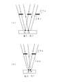
- the thickness of the article can be inspected by irradiating the inspected object 10 with stripe light 25 (see FIG. 4 and the like) obliquely and inspecting the phase shift occurring at the boundary portion of the inspected object 10. It is a thing.
- region of the test object 10 is specified using the difference in the brightness
- the thickness can be inspected by detecting the phase shift of the striped light 25 in FIG.
- the configuration of the thickness inspection apparatus 100 according to the present embodiment will be described in detail with reference to the functional block diagram of FIG.
- the moving means 1 includes a mounting member 11 for mounting the inspection object 10 and a transport mechanism 12 for transporting the mounting member 11 in the horizontal direction.
- the surface of the mounting member 11 is set to a color different from the color of the inspection object 10. For example, when inspecting the inspection object 10 made of a metal color, a member having a slightly dark surface color is used. Composed. However, if the brightness of the dark surface color is darkened, the reflected light cannot be received when the striped light 25 is irradiated. For this reason, it sets to the color which can receive the reflected light of the striped light 25, and can judge clearly the difference in a brightness
- the transport mechanism 12 is configured to move the placement member 11 in a direction orthogonal to the line sensor 21 and is configured by a member such as a transport belt, a motor, or a slide rail.
- the moving means 1 is configured by providing the mounting member 11 and the transport mechanism 12, but may be configured by a worm shaft mechanism or the like.
- the image acquiring unit 2 includes an illuminating unit 22 that irradiates the striped light 25 onto the mounting member 11 and a line sensor 21 that receives the light irradiated by the illuminating unit 22.
- the illuminating means 22 irradiates light at an angle of 45 degrees with respect to the horizontal direction along the carrying direction of the mounting member 11, and alternately has bright and dark slits in front of the light source 23.
- a striped plate 24 is provided to irradiate the mounting member 11 with striped light 25 that alternately repeats light and dark colors. In the case of irradiating the striped light 25, the striped light 25 oblique to the transport direction in the plane of the mounting member 11 is irradiated by 45 degrees.
- the striped light 25 when the striped light 25 is irradiated on the horizontal plane from an angle of 45 degrees with respect to the horizontal direction, the fringe on the side far from the light source 23 becomes unclear as compared to the side near the light source 23.
- the striped plate 24 is disposed at a position where the interval and the freshness of light and darkness can be ignored so that the phase shift at the light and dark intervals can be inspected.
- a light quantity will become small as it goes to the outer side of the test object 10.
- a lens is provided in order to increase the amount of light, the distance between the striped lights 25 is distorted due to the distortion of the lens, and an accurate thickness inspection cannot be performed. Therefore, in this embodiment, for example, a semi-cylindrical cylindrical lens 23a is provided as a light amount correction lens in front of the light source 23 to secure the light amount with respect to the inspection object 10 and to eliminate the distortion of the striped light 25. I am doing so.
- the cylindrical lens 23a When the cylindrical lens 23a is provided, as shown in FIG. 3, the cylindrical lens 23a is arranged so that the cross section in the direction along the fringe line is semicircular and the cross section in the longitudinal direction perpendicular to the fringe line is rectangular. Deploy. If it does in this way, it can be made to condense toward the center of inspection object 10 without producing distortion to the interval of a stripe by cylindrical lens 23a. Then, by adjusting the condensing point of the cylindrical lens 23a to the line sensor 21 (see FIG. 1), the amount of light at the line sensor 21 is increased so that the inspection can be performed accurately.
- the light source 23 and the striped plate 24 are connected as follows. It is configured as follows.
- the light source if a point light source is used, one point of the inspection object 10 is irradiated only with light from one point of the light source, and the reflection is appropriate for the unevenness of the inspection object 10 as shown in FIG. It becomes impossible to reflect light toward the line sensor.
- a surface light source as shown in FIG. 8 (b)
- light can be emitted from various directions of the light source to one point of the inspection object 10.
- the reflected light in various directions can be generated and the reflected light can be incident on the line sensor. Therefore, a light source having a surface light source having a size corresponding to the unevenness angle to be detected of the inspection object 10 is used.
- a collimating lens that makes the light source parallel light is used, so that it can cope with the unevenness angle of the inspection object 10 to be detected.
- a surface light source If such a surface light source is used, the light from the center becomes parallel light passing through the center of the collimating lens, and the light from the end becomes parallel light passing from the end to the center of the collimating lens.
- the light irradiation angle according to the size of the light source can be determined.
- light can be irradiated from various directions with the light intensity kept constant, and irregularities with angles of ⁇ 1 to ⁇ 2 in FIGS. 8B and 8C can be detected.
- an angle to be detected is set, by using a surface light source having a size corresponding to this angle, the unevenness corresponding to the angle can be detected.
- the striped plate 24 can be configured as shown in FIG. That is, the striped plate 24 is arranged so that there are exactly the same number of the light shielding portions 24a and the slit portions 24b within the light width of the condensed light. In this way, when attention is paid to one bright point of the inspection object 10, the light is brightened by the light from the two slit portions 24b, while the dark one point is darkened by the two light shielding portions 24a. On the other hand, if the number of the light shielding portions 24a and the slit portions 24b is different, as shown in FIG.
- the reflected light obtained by such a light source is acquired by the line sensor 21 and stored in the storage means 3 as a two-dimensional image.
- the image stored in the storage unit 3 is an image including the striped light 25 on the mounting member 11 and the striped light 25 on the inspection object 10. In the region A1 where 10 exists, the phase of the striped light 25 is shifted.
- the filtering means 4 extracts an area A1 (see FIG. 5) where the inspection object 10 exists from the image acquired by the line sensor 21.
- the area A1 of the inspection object 10 is extracted based on the difference in luminance between the mounting member 11 and the inspection object 10. Specifically, when the luminance value of the mounting member 11 is low and the luminance value of the inspection object 10 is set to a high state, as shown in the lower diagram of FIG. Since the luminance value of the area A1 of the object 10 is increased, a predetermined luminance width corresponding to the luminance value is set, and the image area A1 having the luminance width is extracted.
- the mounting member 11 is used as a dark color system to extract the luminance of the metallic inspection object 10.
- the inspection object 10 is a dark color system
- the mounting member 11 is extracted.
- the image area A1 having a dark-color luminance width may be extracted with a metallic color.
- the mounting member 11 and the inspection object 10 may be set to the same metal color when the brightness values of the images acquired by the line sensor 21 differ from the height difference.
- the filtering means 4 information relating to the shape of the inspection object 10 is stored in advance in the storage means 3 and stored in the storage means 3 and an image having a predetermined luminance width as shown in FIG. 5. It is detected whether or not the shape of the inspection object 10 matches, and if it matches, it is determined that the area is the area A1 of the inspection object 10.
- the phase difference calculating means 5 calculates the difference between the phase of the striped light 25 in the region A1 of the inspection object 10 and the phase of the striped light 25 irradiated on the mounting member 11.
- phase difference As a first embodiment, on a specific inspection line including the region A1 of the inspection object 10, Fourier transform is performed for each predetermined width, and the frequency and phase are calculated from the real number component and the imaginary number component. Extract. When this phase is extracted, the phase is calculated with reference to a reference point on the line of the line sensor 21, the phase of the striped light 25 in the outer region A4 with reference to this reference point, and the reference point as a reference. The phase difference of the area A1 of the inspection object 10 thus obtained is calculated.
- the frequency of the striped light 25 is the same in the outer area A4 and the area A1 of the inspection object 10, but the inspection object.
- the phase is shifted from the boundary portion of the object 10 as a boundary. This phase shift is proportional to the height of the inspection object 10, and the phase shift increases as the height of the inspection object 10 increases.
- the phase shift is 180 degrees or a multiple thereof, and as shown in FIG. The phase shift is not known at the part.
- an image of the vicinity area A2 obtained by inflating the area A1 of the inspection object 10 is acquired, and it is detected whether or not the striped light 25 is missing on the inspection line in the vicinity area A2.
- the relationship between the thickness of the inspection object 10 and the striped light 25 is a relationship in which the phase is exactly a multiple of 180 degrees
- the striped light 25 is missing on one side of the inspection line. Therefore, the omission of the striped light 25 is extracted, and the phase difference of the inspection object 10 is calculated based on the number.
- the region where the striped light 25 does not exist when one striped light is missing, it is determined that the phase is 180 degrees out of phase, and when two striped lights are missing, It is determined that the phase is 360 degrees.
- a region A2 obtained by expanding the region A1 extracted by template matching or the like is used as the region where the striped light 25 does not exist.
- the second phase difference calculation method When detecting the phase difference, if frequency analysis is performed on the line of the line sensor 21, the thickness at that portion can be detected. For example, when the thickness is discontinuous as shown in FIG. If the position of the line shifts, the thickness will change greatly. In the above embodiment, the brightness of the striped light must be clarified for frequency analysis. Therefore, in the second embodiment, the thickness can be accurately inspected even if there is a discontinuous thickness change, and the thickness can be inspected even when the brightness of the striped light is reduced. ing.
- the acquired two-dimensional image is divided into minute regions that can be regarded as a substantially straight line of striped light, and the direction of the straight line is detected.
- the luminance value is projected in a one-dimensional direction while rotating the minute region, and the direction with the most luminance change is set as the direction of the straight line. That is, when the luminance is projected in a direction orthogonal to the direction of the straight line, the luminance histogram is relatively flat, whereas when the luminance is projected in the direction matching the direction of the straight line, the luminance is The histogram has the largest luminance change only at the position where the straight line exists.
- the direction of the straight line is detected as described above, and, for example, the center point of the straight line is extracted as the representative point of the straight line.
- the phase difference namely, thickness
- the striped light at that position in the state where the inspection object does not exist is stored, and the striped light and For example, a method for calculating the distance can be used.
- the thickness detector 6 calculates the thickness of the inspection object 10 based on this phase difference.
- the value of the thickness is calculated based on the relationship between the angle of the striped light 25, the pitch between light and dark and the phase, and it is determined whether or not the value is within a predetermined reference value range.
- the thickness value is calculated to determine whether the product is good or bad, but the phase difference itself is determined to be the thickness, and the thickness is detected based on the phase difference and the reference phase difference. Also good.
- the quality determination result of the test object 10 by the thickness is output via the output means 9, and at that time, the value of the thickness etc. is output via a display.
- the striped light erasing unit 7 erases the bright and dark image of the striped light 25 acquired by the image acquiring unit 2.
- an image included in the luminance value of the dark stripe portion is erased using a band pass filter.
- the image region A1 of the inspection object 10 obtained by the previous filtering means 4 is extracted, and the dark striped portion in the image region A1 is erased.
- an image obtained by removing dark stripes from the image area A1 of the inspection object 10 is extracted.
- the image energy component including the striped light 25 is converged by performing a two-dimensional Fourier transform on the obtained image, and a mask is applied to that portion.
- a method of erasing by applying can also be used.
- the surface inspection means 8 inspects the formation state of the surface of the inspection object 10 based on the image of the inspection object 10 obtained by the striped light erasing means 7.
- various methods can be used. For example, a pixel having a predetermined luminance value that is generated when a flaw is present is extracted, and a defect is determined depending on the size of the area of the pixel. A method for discriminating is used. Then, the determination result of good / bad is output via the output means 9.
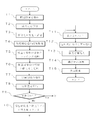
- the conveyance mechanism 12 when inspecting the thickness of the inspection object 10 and the formation state of the surface, the conveyance mechanism 12 is driven in a state where the inspection object 10 is placed on the placement member 11, and moved to below the line sensor 21. (Step S1). And the striped light 25 is irradiated from the diagonal direction through the illumination means 22 (step S2), reflected light is acquired with the line sensor 21, and the two-dimensional image is memorize
- a predetermined brightness width is read from the storage means 3 as a brightness value corresponding to the inspection object 10, and an image area included in the brightness width is extracted (step S4).
- the image area is matched with information related to the shape of the inspection object 10 stored in advance in the storage means 3 (step S5), and a matching image area A1 is extracted.
- step S6 the image region A1 of the inspection object 10 and the striped light 25 in the region on the mounting member 11 are Fourier transformed for each predetermined line, and the respective phases are calculated to obtain the phase difference (step S6). Based on the phase difference, the thickness of the inspection object 10 is calculated (step S7), and compared with the reference value, the judgment result of good / bad is output (step S8).
- step S9 After inspecting the thickness of the inspection object 10 in this way, dark stripes are erased from the striped light 25 irradiated on the surface of the inspection object 10 via the striped light erasing means 7 (step) S9) The surface formation state is inspected based on the image of the inspection object 10 obtained by the erasure (step S10).
- the image of inspection object 10 can be acquired from the difference in the brightness of mounting member 11 and inspection object 10, the phase of the striped light of the image within this luminance range, and other than that By seeing the difference from the phase of the striped light in the region, it is possible to reduce the arithmetic processing in the useless region.
- the inspection object 10 when inspecting the thickness of the inspection object 10 and the formation state of the surface, the inspection object 10 is placed on the mounting member 11, and the transport mechanism 12 is driven to move below the line sensor 21. (Step T1). Then, the striped light 25 is irradiated from the oblique direction through the illumination unit 22 (step T2), and the reflected light is acquired by the line sensor 21 and stored in the storage unit 3 as a two-dimensional image (step T3).
- a predetermined luminance width is read from the storage means 3 as a luminance value corresponding to the reflected luminance of the inspection object 10 from the image stored in the storage means 3, and an image area included in the luminance width is acquired ( In step T4), the image area is matched with information relating to the shape of the inspection object 10 stored in advance in the storage means 3 (step T5), and a matching image area A1 is extracted.
- the image area A1 of the inspection object 10 is expanded (step T6), and the image area A1 in the inspection object 10 and the vicinity area A2 where the expansion process is performed. Is extracted (step T7). Then, Fourier transformation is performed on the striped light 25 in the outer area A4 on the mounting member 11 and the inspection line in the image area A1 of the inspection object 10 to obtain a phase difference between the image area A1 of the inspection object 10 ( Step T8). At this time, when there is no phase difference (step T9: No), it is determined whether or not there is a region where the striped light 25 does not exist in the vicinity region A2.
- the missing stripe light 25 is counted (step T10), and the phase difference is shifted by 180 ⁇ n according to the count number n. (Step T11). Then, the thickness of the inspection object 10 is calculated based on the phase difference (step T12), and the thickness result is output by comparison with the reference value stored in the storage means 3 (step T13).
- step T14 After inspecting the thickness of the inspection object 10, dark stripes are erased from the striped light 25 irradiated on the surface of the inspection object 10 via the striped light 25 erasing means (step T14). ) The surface formation state is inspected based on the image of the inspection object 10 obtained by the erasure (step T15).
- the signal on the inspection line is frequency-analyzed to detect the phase difference.
- the position of the striped light by image processing is detected.
- the phase can be detected by calculating the distance between the position and the original striped light.
- the same processing is used for the conveyance of the inspection object 10, the acquisition of the image, the elimination of the striped light, and the surface inspection method.
- step U1 when a two-dimensional image is acquired from the inspection object 10 irradiated with the striped light (step U1), the image is divided into minute regions (step U2). Then, the luminance information is projected in a one-dimensional direction while rotating the minute area, and the angle at which the luminance change is greatest is extracted (step U3), and the direction is set as the direction in which the striped light faces in the minute area.
- a central point which is a representative point of the striped light, is extracted in the minute region (step U4).
- step U5 by irradiating the striped light in a state where the inspection object 10 is not placed in advance and calculating the distance from the striped light at the same position in that state (step U5), the thickness at that position is calculated. Calculate (step U6).
- the thickness at each position can be inspected even when the thickness changes discontinuously.
- the position where the luminance change is the largest is extracted by rotating the minute area so that the position of the striped light is extracted. Therefore, even if the luminance difference between the striped light and the dark part is reduced, the phase difference is accurately determined. Since it is possible to obtain the image and to reduce the difference in luminance, it is possible to perform defect inspection at the same time.
- the colors of the mounting member 11 and the inspection object 10 are separated.
- the same color is used. You may keep it.
- the striped light 25 is irradiated obliquely downward 45 degrees from the horizontal plane.
- parallel light such as laser light is provided as the light source 23.
- a lens may be provided between the light source 23 and the striped plate 24 to refract light from the light source 23 into parallel light.
- the phase difference is obtained based on the number of intersections between the virtual striped light 25 and the inspection line in the vicinity area A ⁇ b> 2 of the inspection object 10.
- the phase difference may be obtained based on the size and width of the region where the striped light 25 does not exist, instead of the number of intersections.
- the width of the region where the striped light 25 does not exist is divided by the pitch width of the striped light 25 to determine how many striped lights 25 do not exist. The phase difference may be obtained.
- DESCRIPTION OF SYMBOLS 100 Thickness inspection apparatus 1 ... Moving means 11 ... Mounting member 12 ... Conveyance mechanism 2 ... Image acquisition means 21 ... Line sensor 22 ... Illumination means 23 ... Light source 23a ... Cylindrical lens 24 ... Striped plate 25 ... Striped light 3 ... Storage means 4 ... Filtering means 5 ... Phase difference calculation means 6 ... Thickness detection means 7 ... Striped light erasing means 8 ... surface inspection means 9 ... output means 10 ... inspection object A1 ... inspection object area A2 ... vicinity area A3 ... noise A4 ... Outer area
Landscapes
- Physics & Mathematics (AREA)
- General Physics & Mathematics (AREA)
- Engineering & Computer Science (AREA)
- Computer Vision & Pattern Recognition (AREA)
- Length Measuring Devices By Optical Means (AREA)
Abstract
La présente invention concerne un dispositif de détection d'épaisseur pouvant détecter de manière précise l'épaisseur d'un objet cible en peu de temps. De la lumière zonée (25) est irradiée selon un angle dans la direction du mouvement le long d'un élément de montage (11) et une image est générée à partir de la lumière réfléchie. Un dispositif de détection d'épaisseur (100) qui détecte l'épaisseur d'un produit en détectant des déphasages comporte : un moyen de filtration (4) qui acquiert une image de l'objet cible (10) parmi des images acquises par un capteur linéaire (21) par la différence entre la luminance de l'élément de montage (11) et la luminance de l'objet cible (10) ; une phase d'une région (A1) de l'objet cible (10) acquise par le moyen de filtration (4) ; et un moyen de calcul de la différence de phase (5) qui demande la différence de phase dans la phase de la lumière zonée (25) qui irradie l'élément de montage (11). En fonction de la différence de phase demandée par le moyen de calcul de la différence de phase (5), la qualité de l'objet cible est déterminée.
Priority Applications (1)
| Application Number | Priority Date | Filing Date | Title |
|---|---|---|---|
| JP2012523863A JPWO2012005226A1 (ja) | 2010-07-05 | 2011-07-04 | 厚み検査装置 |
Applications Claiming Priority (2)
| Application Number | Priority Date | Filing Date | Title |
|---|---|---|---|
| JP2010-153474 | 2010-07-05 | ||
| JP2010153474 | 2010-07-05 |
Publications (1)
| Publication Number | Publication Date |
|---|---|
| WO2012005226A1 true WO2012005226A1 (fr) | 2012-01-12 |
Family
ID=45441205
Family Applications (1)
| Application Number | Title | Priority Date | Filing Date |
|---|---|---|---|
| PCT/JP2011/065311 Ceased WO2012005226A1 (fr) | 2010-07-05 | 2011-07-04 | Dispositif de détection d'épaisseur |
Country Status (2)
| Country | Link |
|---|---|
| JP (1) | JPWO2012005226A1 (fr) |
| WO (1) | WO2012005226A1 (fr) |
Citations (7)
| Publication number | Priority date | Publication date | Assignee | Title |
|---|---|---|---|---|
| JPS61274207A (ja) * | 1985-05-20 | 1986-12-04 | Fujitsu Ltd | 物体の三次元計測方法 |
| JPS6298204A (ja) * | 1985-10-25 | 1987-05-07 | Omron Tateisi Electronics Co | 物体認識方法およびその装置 |
| JPH06226668A (ja) * | 1993-01-29 | 1994-08-16 | Daifuku Co Ltd | 物品位置検出装置 |
| JPH0961113A (ja) * | 1995-08-28 | 1997-03-07 | Nec Robotics Eng Ltd | ラベル位置検出装置 |
| JP2711042B2 (ja) * | 1992-03-30 | 1998-02-10 | シャープ株式会社 | クリーム半田の印刷状態検査装置 |
| JPH1196378A (ja) * | 1997-09-17 | 1999-04-09 | Niigata Eng Co Ltd | 積荷位置姿勢認識装置 |
| JP2007114071A (ja) * | 2005-10-20 | 2007-05-10 | Omron Corp | 三次元形状計測装置、プログラム、コンピュータ読み取り可能な記録媒体、及び三次元形状計測方法 |
-
2011
- 2011-07-04 JP JP2012523863A patent/JPWO2012005226A1/ja not_active Withdrawn
- 2011-07-04 WO PCT/JP2011/065311 patent/WO2012005226A1/fr not_active Ceased
Patent Citations (7)
| Publication number | Priority date | Publication date | Assignee | Title |
|---|---|---|---|---|
| JPS61274207A (ja) * | 1985-05-20 | 1986-12-04 | Fujitsu Ltd | 物体の三次元計測方法 |
| JPS6298204A (ja) * | 1985-10-25 | 1987-05-07 | Omron Tateisi Electronics Co | 物体認識方法およびその装置 |
| JP2711042B2 (ja) * | 1992-03-30 | 1998-02-10 | シャープ株式会社 | クリーム半田の印刷状態検査装置 |
| JPH06226668A (ja) * | 1993-01-29 | 1994-08-16 | Daifuku Co Ltd | 物品位置検出装置 |
| JPH0961113A (ja) * | 1995-08-28 | 1997-03-07 | Nec Robotics Eng Ltd | ラベル位置検出装置 |
| JPH1196378A (ja) * | 1997-09-17 | 1999-04-09 | Niigata Eng Co Ltd | 積荷位置姿勢認識装置 |
| JP2007114071A (ja) * | 2005-10-20 | 2007-05-10 | Omron Corp | 三次元形状計測装置、プログラム、コンピュータ読み取り可能な記録媒体、及び三次元形状計測方法 |
Also Published As
| Publication number | Publication date |
|---|---|
| JPWO2012005226A1 (ja) | 2013-09-02 |
Similar Documents
| Publication | Publication Date | Title |
|---|---|---|
| JP6447637B2 (ja) | 表面欠陥検出装置、表面欠陥検出方法、及び鋼材の製造方法 | |
| JP5337050B2 (ja) | 車両用成形ガラスのひずみを反射された光学像により自動的に定量分析する方法 | |
| JP5347418B2 (ja) | 表面欠陥検査システム、方法及びプログラム | |
| WO2015098929A1 (fr) | Procédé de détection d'un défaut de surface et dispositif de détection d'un défaut de surface | |
| JP2020008501A (ja) | 表面欠陥検出装置及び表面欠陥検出方法 | |
| JP5347661B2 (ja) | 帯状体の表面検査装置、表面検査方法及びプログラム | |
| JP5194529B2 (ja) | 表面欠陥検査システム、方法及びプログラム | |
| US10955354B2 (en) | Cylindrical body surface inspection device and cylindrical body surface inspection method | |
| JP2017187348A (ja) | 表面欠陥検査システム、方法及びプログラム | |
| JP2021056183A (ja) | ワークの表面欠陥検出装置及び検出方法、ワークの表面検査システム並びにプログラム | |
| JP2004003930A (ja) | 光学的形状測定装置及び光学的形状測定方法 | |
| JP5978002B2 (ja) | 検査方法及び外観検査装置 | |
| JP6387909B2 (ja) | 表面欠陥検出方法、表面欠陥検出装置、及び鋼材の製造方法 | |
| JP6624161B2 (ja) | 塗装金属板の塗膜膨れ幅測定装置および塗装金属板の塗膜膨れ幅の測定方法 | |
| JP2010085165A (ja) | 表面検査装置および表面検査方法 | |
| WO2012005226A1 (fr) | Dispositif de détection d'épaisseur | |
| US20190355110A1 (en) | Cross talk reduction | |
| JP2004191070A (ja) | 塗装面の検査装置 | |
| CN111108367A (zh) | 透射光学系统的检查装置及使用该装置的膜缺陷检查方法 | |
| JPH09105618A (ja) | 物体の平滑な面の欠陥検査方法及び装置並びに物体表面の粗さ測定方法及び装置 | |
| JP5266118B2 (ja) | 物体表面の欠陥検査方法および欠陥検査装置 | |
| JP6765645B2 (ja) | ろう材パターンの検査方法 | |
| JPH06137845A (ja) | 鋼板の表面凹凸縞検査装置 | |
| JP2001050720A (ja) | 表面検査方法および装置 | |
| JP2024109397A (ja) | 電池外装体の外観検査装置 |
Legal Events
| Date | Code | Title | Description |
|---|---|---|---|
| 121 | Ep: the epo has been informed by wipo that ep was designated in this application |
Ref document number: 11803560 Country of ref document: EP Kind code of ref document: A1 |
|
| WWE | Wipo information: entry into national phase |
Ref document number: 2012523863 Country of ref document: JP |
|
| NENP | Non-entry into the national phase |
Ref country code: DE |
|
| 122 | Ep: pct application non-entry in european phase |
Ref document number: 11803560 Country of ref document: EP Kind code of ref document: A1 |