WO2012008459A1 - Dispositif de revêtement électrostatique - Google Patents
Dispositif de revêtement électrostatique Download PDFInfo
- Publication number
- WO2012008459A1 WO2012008459A1 PCT/JP2011/065902 JP2011065902W WO2012008459A1 WO 2012008459 A1 WO2012008459 A1 WO 2012008459A1 JP 2011065902 W JP2011065902 W JP 2011065902W WO 2012008459 A1 WO2012008459 A1 WO 2012008459A1
- Authority
- WO
- WIPO (PCT)
- Prior art keywords
- liquid
- discharge port
- electrostatic coating
- flow path
- coating apparatus
- Prior art date
- Legal status (The legal status is an assumption and is not a legal conclusion. Google has not performed a legal analysis and makes no representation as to the accuracy of the status listed.)
- Ceased
Links
Images





Classifications
-
- B—PERFORMING OPERATIONS; TRANSPORTING
- B05—SPRAYING OR ATOMISING IN GENERAL; APPLYING FLUENT MATERIALS TO SURFACES, IN GENERAL
- B05B—SPRAYING APPARATUS; ATOMISING APPARATUS; NOZZLES
- B05B5/00—Electrostatic spraying apparatus; Spraying apparatus with means for charging the spray electrically; Apparatus for spraying liquids or other fluent materials by other electric means
- B05B5/16—Arrangements for supplying liquids or other fluent material
- B05B5/1608—Arrangements for supplying liquids or other fluent material the liquid or other fluent material being electrically conductive
- B05B5/1616—Arrangements for supplying liquids or other fluent material the liquid or other fluent material being electrically conductive and the arrangement comprising means for insulating a grounded material source from high voltage applied to the material
-
- B—PERFORMING OPERATIONS; TRANSPORTING
- B05—SPRAYING OR ATOMISING IN GENERAL; APPLYING FLUENT MATERIALS TO SURFACES, IN GENERAL
- B05B—SPRAYING APPARATUS; ATOMISING APPARATUS; NOZZLES
- B05B5/00—Electrostatic spraying apparatus; Spraying apparatus with means for charging the spray electrically; Apparatus for spraying liquids or other fluent materials by other electric means
- B05B5/025—Discharge apparatus, e.g. electrostatic spray guns
- B05B5/0255—Discharge apparatus, e.g. electrostatic spray guns spraying and depositing by electrostatic forces only
-
- B—PERFORMING OPERATIONS; TRANSPORTING
- B05—SPRAYING OR ATOMISING IN GENERAL; APPLYING FLUENT MATERIALS TO SURFACES, IN GENERAL
- B05B—SPRAYING APPARATUS; ATOMISING APPARATUS; NOZZLES
- B05B5/00—Electrostatic spraying apparatus; Spraying apparatus with means for charging the spray electrically; Apparatus for spraying liquids or other fluent materials by other electric means
- B05B5/025—Discharge apparatus, e.g. electrostatic spray guns
- B05B5/053—Arrangements for supplying power, e.g. charging power
- B05B5/0533—Electrodes specially adapted therefor; Arrangements of electrodes
-
- B—PERFORMING OPERATIONS; TRANSPORTING
- B05—SPRAYING OR ATOMISING IN GENERAL; APPLYING FLUENT MATERIALS TO SURFACES, IN GENERAL
- B05B—SPRAYING APPARATUS; ATOMISING APPARATUS; NOZZLES
- B05B5/00—Electrostatic spraying apparatus; Spraying apparatus with means for charging the spray electrically; Apparatus for spraying liquids or other fluent materials by other electric means
- B05B5/08—Plant for applying liquids or other fluent materials to objects
- B05B5/087—Arrangements of electrodes, e.g. of charging, shielding, collecting electrodes
-
- B—PERFORMING OPERATIONS; TRANSPORTING
- B05—SPRAYING OR ATOMISING IN GENERAL; APPLYING FLUENT MATERIALS TO SURFACES, IN GENERAL
- B05B—SPRAYING APPARATUS; ATOMISING APPARATUS; NOZZLES
- B05B1/00—Nozzles, spray heads or other outlets, with or without auxiliary devices such as valves, heating means
- B05B1/14—Nozzles, spray heads or other outlets, with or without auxiliary devices such as valves, heating means with multiple outlet openings; with strainers in or outside the outlet opening
- B05B1/16—Nozzles, spray heads or other outlets, with or without auxiliary devices such as valves, heating means with multiple outlet openings; with strainers in or outside the outlet opening having selectively- effective outlets
Definitions
- the present invention relates to an electrostatic coating apparatus that can apply a liquid such as a chargeable oil to an object to be coated, and in particular for lubrication and rust prevention of steel materials and for preventing food from sticking to a mold.
- the present invention relates to an electrostatic coating apparatus for applying oil to an outer surface of a steel material or a mold or for forming a coating film.
- Patent Literature 1 and Patent Literature 2 disclose conventional electrostatic coating apparatuses.
- the electrostatic coating apparatus of Patent Document 1 includes a housing having a hollow portion for accommodating a fluid material, and a nozzle communicating with the hollow portion. The nozzle is formed by joining a plate-like upper nozzle lip and a plate-like lower nozzle lip.
- a flow path is formed between the upper nozzle lip and the lower nozzle lip, and the front edge of the lower nozzle lip protrudes from the front edge of the upper nozzle lip. Furthermore, the slots defined by the leading edges of the upper and lower nozzle lips are rectangular openings.
- a shim which is a metal plate member for adjusting the gap of the flow path, extends to the vicinity of the slot, and the amount of liquid discharged from the slot by the shim can be adjusted.
- the shim is electrically connected to a high voltage power source through the housing, and the liquid in the flow path is charged through the shim.
- the liquid supplied into the housing is charged in the flow path, passes through the slot, and is discharged from the front edge portion of the lower nozzle lip.
- the conventional electrostatic coating apparatus coats a relatively wide area of an object to be coated with liquid, the front edge of the lower nozzle lip is formed in a straight line in the longitudinal direction of the lower nozzle lip, thereby increasing the coating area. is doing.
- Patent Document 2 has a configuration in which an inductor bar is added to the electrostatic coating apparatus of Patent Document 1. Similar to Patent Document 1, a mist-like liquid is applied to a rectangular region of an object to be coated.
- the slot is rectangular, it is difficult to stably form a meniscus extending between the upper nozzle lip and the lower nozzle lip. As a result, the discharge direction and the discharge amount of the liquid discharged from the lower nozzle lip are not stable, and it is difficult to stably and uniformly apply the liquid to the object to be coated.
- an object of the present invention is to provide an electrostatic coating apparatus that can uniformly apply a liquid to an object to be coated.
- a first aspect of the electrostatic coating apparatus of the present invention includes a flow path through which a chargeable oil-based liquid flows and a circle communicating with one end of the flow path.
- An apparatus housing having a single or a plurality of nozzle assemblies having a discharge port in a shape, and a liquid introduction path communicating with the other end of the flow path, to which the single or a plurality of nozzle assemblies are mounted
- a charging electrode that extends into the liquid introduction path and charges the oil-based liquid with a charge, and the discharge port expands along the discharge direction of the oil-based liquid .
- the electrostatic coating apparatus of a 1st aspect Comprising: In the said flow path of each of the said single or several nozzle assembly, the said oil system Control means for controlling the liquid to be supplied at 0.5 cc / min to 4 cc / min is provided, and the diameter of the discharge port is 1 mm to 5 mm.
- the electrostatic coating apparatus of this invention is an electrostatic coating apparatus of the 1st or 2nd aspect, Comprising: The thickness of the side wall part which forms the said flow path is constant.
- the voltage charged from the charging electrode to the oil-based liquid is It is +10 KV or more and +40 KV or less, or ⁇ 40 KV or more and ⁇ 10 KV or less.
- the diameter of the flow path is directed toward the discharge port. Identical or gradually decreasing.
- the electrostatic coating apparatus according to any one of the first to fifth aspects, wherein the discharge grounding means for grounding the charging electrode is provided. Is provided.
- the electrostatic coating apparatus according to any one of the first to sixth aspects, wherein the single or plural electrostatic coating apparatuses are concentric with the discharge port.
- a ring-shaped resistor that is spaced apart from each of the nozzle assemblies in the discharge direction, and a potential difference is provided between the charging electrode and the resistor.
- oil-type liquid in this specification means the liquid containing oil components, such as lubricating oil, mold release oil, and antirust oil.
- An electrostatic coating apparatus uses a nozzle having a circular discharge port, supplies charged liquid to a flow path in the nozzle, and atomizes the liquid discharged from the discharge port. . Therefore, the shape of the meniscus formed at the discharge port is uniform, and becomes circular when viewed from the front. In addition, since there is no obstacle that obstructs the meniscus at and near the discharge port, the meniscus can be stably and reliably formed at the discharge port. As a result, the liquid at the discharge port can be discharged stably.
- FIG. 4 is a cross-sectional view taken along line IV-IV in FIG. It is an enlarged view of the V section of FIG. (A) is a sectional view of the nozzle for explaining the behavior of the meniscus formed at the nozzle outlet and the atomization of the liquid, and (b) is along the line VI-VI in FIG. 6 (a).
- FIG. 4 is a cross-sectional view taken along line IV-IV in FIG. It is an enlarged view of the V section of FIG. (A) is a sectional view of the nozzle for explaining the behavior of the meniscus formed at the nozzle outlet and the atomization of the liquid, and (b) is along the line VI-VI in FIG. 6 (a).
- FIG. 7C is a diagram showing the discharged liquid along line VII-VII in FIG. 6A. It is sectional drawing of the modification of a nozzle assembly. It is a partial section front view showing typically the electrostatic painting device concerning a 2nd embodiment. It is a bottom view of the electrostatic coating apparatus of FIG. (A) is a front view of the nozzle assembly shown in FIG. 8, (b) is a top view of FIG. 10 (a), and (c) is a bottom view of FIG. 10 (a). is there.
- FIG. 11 is a cross-sectional view taken along line XI-XI in FIG. It is an enlarged view of the XII section of Drawing 11 for explaining the behavior of the meniscus formed in a discharge mouth, and atomization of liquid.
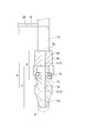
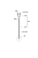
- FIG. 1 is a partial sectional front view schematically showing the electrostatic coating apparatus 1 according to the first embodiment
- FIG. 2 is a bottom view of the electrostatic coating apparatus of FIG.
- the electrostatic coating apparatus 1 includes a flow path 2 (see FIG. 4) through which a chargeable oil-based liquid (hereinafter referred to as a liquid) flows, and a circular discharge port 7d communicating with one end of the flow path 2.
- a nozzle housing 6 having a liquid introduction passage 13 communicating with the other end of the flow path 2 and holding the nozzle assembly 6, and in the liquid introduction passage 13 (see FIG. 4). And is arranged concentrically with the discharge port 7d and charged in the discharge direction (downward in FIG. 1 (ie, downward in the vertical direction)).
- a ring-shaped resistor 25 The nozzle assembly 6 according to this embodiment includes a nozzle 7 and a nozzle holding portion 8.
- the discharge port 7d expands in the liquid discharge direction (downward in the vertical direction in FIG. 1) (see FIG. 4), and a potential difference is provided between the charging electrode 9 and the resistor 25. Details of the flow path 2 and the discharge port 7d will be described later.
- the electrostatic coating apparatus 1 includes an apparatus housing 11 into which a nozzle holding portion 8 that holds the nozzle 7 is screwed.
- the apparatus housing 11 includes a main body part 11a and a fixing part 11b, and the fixing part 11b is fixed to the main body part 11a by a fastening member 15 such as a screw.
- the main body 11a is a square hexahedron when viewed from below
- the fixed part 11b is a hexahedron that is rectangular when viewed from below.
- a liquid supply pipe 17 connected to a storage portion 43 for storing a liquid is fixed to one end portion of a through hole extending in the longitudinal direction inside the main body portion 11a, that is, a liquid introduction path 13 (see FIG. 1). .
- the other end of the liquid introduction path 13 communicates with the liquid path 5 (see FIG. 4) of the flow path 2 of the nozzle holding unit 8.
- a known pump 45 is provided to supply liquid from the reservoir 43 to the liquid supply pipe 17.
- the pump 45 is electrically connected to a control unit 45 (for example, a microcomputer) that controls the operation of the electrostatic coating apparatus 1, and the pump 45 is operated by a signal from the control unit 41, and a predetermined amount of liquid is supplied to the liquid supply pipe 17. To the flow path 2 of the nozzle assembly 6.
- a control unit 45 for example, a microcomputer
- a cable introduction groove 21 extending substantially parallel to the liquid introduction path 13 of the main body portion 11a is provided on the surface of the fixing portion 11b facing the main body portion 11a.
- a power cable 23 connected to a power source 47 that supplies a high-voltage current extends in the cable introduction groove 21.
- the front end portion 23a of the power cable 23 is electrically connected to the charging electrode 9 composed of a rod-shaped conductive member.
- the power supply 47 is electrically connected to the control means 41 of the electrostatic coating apparatus 1, and applies a predetermined voltage from the electrode to the electrode 9 under the control of the control means 41.
- the main body portion 11a is provided with an electrode accommodation hole 29 that extends in the radial direction of the liquid introduction path 13 and continues to the liquid path 5 from one side surface of the main body portion 11a.
- the fixing portion 11b is fixed to the main body portion 11a in a state where the power cable 23 is disposed in the cable introduction groove 21 so that the charging electrode 9 extends into the electrode receiving hole 29 of the main body portion 11a. Needless to say, the liquid in the liquid introduction path 13 does not flow into the electrode accommodation hole 29.
- a resistor 25 (a member held lower than the potential of the charging electrode and higher than the ground potential) 25 is attached to the main body 11a.
- the resistor 25 includes a ring portion 25 a that is a ring-shaped metal member, and a fixing member 25 b for fixing the ring portion 25 a to the apparatus housing 11.
- the ring portion 25a is arranged so that its axis is aligned with the central axis C of the discharge port 7d.
- the ring portion 25a of the resistor 25 includes a discharge port 7d and a surface near the discharge port 7d and extending perpendicularly to the central axis C, and a liquid on the object 33 to be coated along the central axis C. It fixes so that it may be located between the surfaces to be coated. By fixing so that the ring portion 25 is disposed within this range, the dimension of the liquid coating region (see FIG. 6C) can be appropriately changed.
- the fixing member 25b includes a vertical portion extending in the vertical direction in a front view of FIG. 1, an inclined portion extending in a direction inclined at a predetermined angle with respect to the vertical direction, and continuing to the vertical portion; A horizontal portion extending in the horizontal direction and continuing to the inclined portion. Further, the horizontal portions of a plurality (three in the present embodiment) of the fixing members 25b are fastened by bolts and nuts 27 (see FIG. 2) at equal intervals in the circumferential direction of the ring portion 25a.
- the vertical portion of the fixing member 25b is fixed to the side surface of the main body portion 11a.
- the outer diameter, the inner diameter, and the radial dimension of the ring portion 25a are appropriately set depending on the type of liquid to be discharged, conductivity, discharge amount, current magnitude of the high voltage source, and the like.
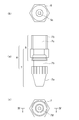
- FIGS. 3A is a front view of the nozzle assembly 6 shown in FIG. 1, FIG. 3B is a top view of FIG. 3A, and FIG. 3C is FIG. 4 is a cross-sectional view taken along line IV-IV (diameter direction of the flow path 2) of FIG. 3C, and FIG. 5 is an enlarged view of a portion V of FIG.
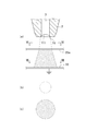
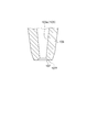
- FIG. 6A is a cross-sectional view of the nozzle 7 for explaining the behavior of the meniscus 111 formed in the discharge port 7d and the atomization of the liquid
- FIG. 6B is a line of FIG. 6A.
- FIG. 7C is a diagram showing the liquid ejected along VI-VI
- FIG. 6C is a diagram showing the liquid ejected along line VII-VI in FIG.
- the nozzle 7 shown in FIG. 6 is the same as the nozzle 7 shown in FIG.
- the nozzle 7 is provided with a flow path constituting path 3 that constitutes the flow path 2 and extends in a straight line through the nozzle 7.
- the nozzle 7 has a discharge port 7 d that is provided at the tip 7 a and communicates with the flow path constituting path 3.
- a nozzle holding part 8 is attached to the rear end part 7 b of the nozzle 7, and a liquid path 5 extending in the longitudinal direction of the nozzle holding part 8 communicates with the flow path constituting path 3 of the nozzle 7.
- the flow path 2 is constituted by the flow path constituting path 3 and the fluid path 5.
- the flow path constituting path 3 and the liquid path 5 have the same diameter and a circular shape.
- the opening provided in the rear end portion 8 b of the nozzle holding portion 8 is a supply port 5 c and continues to the liquid path 5.
- the nozzle 7 and the nozzle holding part 8 are connected to each other via an O-ring 16. Accordingly, the liquid flows out of the flow path constituting path 3 and the fluid path 5 at the connection portion between the flow path constituting path 3 and the fluid path 5, and the foreign matter from the outside of the nozzle assembly 6 flows into the flow path constituting path 3 and the fluid path. No entry into 5
- the discharge port 7d of the nozzle 7 connects the inner peripheral surface 3a defining the flow path constituting path 3 and the front end surface 7e of the nozzle 7, and the diameter of the discharge port 7d becomes closer to the front end surface 7e.
- the taper surface gradually increases (expands along the discharge direction).
- the nozzle 7 and the nozzle holding portion 8 should be formed from any material that is electrically conductive and electrically insulating. Can do. *
- a uniform meniscus 111 is formed at the discharge port 7d as shown in FIG.
- the liquid level at the boundary between the flow path constituting path 3 and the discharge port 7d protrudes in the direction of the flow path constituted path 3 (upward in the vertical direction) and discharges.
- a meniscus 111 symmetric about the center axis C of the outlet 7d is formed.
- the liquid reaching the tip 7f of the discharge port 7d is drawn by the coating object 33 having a potential difference with respect to the potential supplied to the charging electrode 9 as described later, and flies downward.
- the inventors have formed a meniscus that is well-balanced because no member or the like that inhibits the formation and behavior of the meniscus extends in the discharge port 7d and its vicinity, and the discharge port is circular. I got the knowledge that. As a result, uniform coating can be performed on the object to be coated.
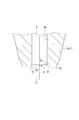
- the discharge port 7d has a predetermined expansion angle ⁇ with respect to the central axis C direction (vertical direction in FIG. 5) in the diametrical cross section, the discharge port 7d is uniform with respect to the coating region of the object 33
- the knowledge that the quantity of liquid adheres is acquired. More specifically, as shown in FIG. 5, when the discharge port 3 is viewed in a cross section in the diameter direction, the discharge port tangent D at the tip 7f connected to the front end surface 7e of the discharge port 7d and the central axis of the discharge port 7d
- the discharge port 7d is configured such that the angle with the center C, that is, the expansion angle ⁇ is greater than 0 degree and less than 90 degrees.
- the expansion angle ⁇ is 0 degrees or less (that is, the diameter of the discharge port 7d is the same as the diameter of the flow path constituting path 203 or smaller than the diameter of the flow path constituting path 203 on the front end face 7e side)
- the discharge is performed.
- the tendency of the liquid to fly in the direction of the central axis C becomes strong, and the liquids that fly fly collide with each other in the process of reaching the object to be coated, so that the liquid is uniformly applied to the object to be coated. Not reach.
- the spread angle ⁇ is 90 degrees or more (that is, when the discharge port 7d has the same diameter as the flow path 202 (flow path constituting path 203)), the spread angle ⁇ is 0 degrees or less.
- the discharged liquid has a strong tendency to fly in the direction of the central axis C, and the flying liquid collides in the process of reaching the object 33 and the liquid does not reach the object 33 uniformly. .
- the charging electrode 9 is disposed in the apparatus housing 11 and the liquid is charged in the apparatus housing 11 before the liquid is supplied into the flow path 2 of the nozzle assembly 6. It is. Therefore, compared to the conventional configuration in which charging is performed in the vicinity of the discharge port of the nozzle assembly, it is less affected by the external atmosphere (for example, atmospheric humidity). Therefore, according to the configuration of this embodiment, the charging process is performed stably and reliably. be able to. Moreover, since the area
- the operation of the electrostatic coating apparatus 1 will be described.
- the electrostatic coating apparatus 1 is oriented such that the nozzle 7 of the electrostatic coating apparatus 1 is positioned vertically below the workpiece 33 (see FIG. 6).
- the liquid is introduced from the storage unit 43 by the pump 45 into the liquid path 5 of the nozzle holding unit 8 through the liquid supply pipe 17.
- the liquid in the liquid path 5 is charged with a high voltage (for example, a potential of ⁇ 80 kV) by the charging electrode 12.
- the negatively charged liquid flows through the flow path constituting path 3 vertically downward, is discharged from the front end 7f of the discharge port 7d, and has a potential difference with the charging electrode 9 (for example, the potential is ⁇ 20 kV) (FIGS. 6A and 6B).
- the charging electrode 9 and the resistor 25 have the same polarity charge, so that the liquid does not reach the resistor 25 and is grounded. Head to the object 33 being painted. Further, since the liquid that forms a meniscus at the discharge port 7d is charged with the same polarity as that of the resistor 25, the liquid liquid particles are repelled and atomized (see FIG. 6C).
- the pressure applied to the liquid in order to supply the liquid from the storage portion 43 into the flow path 2 is not so large as to discharge the liquid from the discharge port 7d.
- the diffusion radius of the liquid discharged from the discharge port 7d depends on the diameter of the resistor 25, the liquid supply speed, and the like.
- the electrostatic coating apparatus 1 of the present embodiment includes a discharge grounding device 51 which is a discharge grounding means for releasing electric charge remaining on the charging electrode 9, the nozzle assembly 6, and the like. Even after power supply from the power supply 47 to the charging electrode 9 is cut off by a signal from the control means 41, if charge remains in the charging electrode 9, there is a risk of liquid being discharged from the discharge port 207d, There is a risk of electric shock. Therefore, the discharge ground device 51 is provided, and the timing at which the power supply 47 is turned off and the timing at which the discharge ground device 51 is operated are synchronized by the control means 41 to prevent the above-mentioned undesirable situation.
- the discharge grounding device 51 is immersed in the insulating liquid 55, an electromagnetic coil 53 that is turned on and off by the control means 41, an insulating liquid tank 56 that contains an insulating liquid 55 having electrical insulating properties such as insulating oil and pure water, and the like. And a pair of terminals 57 and 59 that are spaced apart from each other, and a conductive movable piece 61 that can be electrically connected between the terminals 57 and 59. One terminal 57 is electrically connected to the power cable 23 and the other terminal 59 is grounded.
- the movable piece 61 moves to a position away from the pair of terminals 57 and 59 (to the electromagnetic coil 53 side) by electromagnetic force.
- the electromagnetic coil 53 is turned off, the electromagnetic force disappears, and the movable piece 61 returns to a position where the movable piece 61 is in contact with both terminals 57 and 59 (a state where the movable piece 61 is indicated by a two-dot chain line) by an elastic member (not shown).
- the liquid supply by the pump 45 and the voltage application by the power source 47 are stopped by the signal from the control means 41, and the electromagnetic coil 53 is turned off.
- the terminals 57 and 59 of the discharge grounding device 51 are short-circuited, and the charge remaining on the charging electrode 9 and the nozzle assembly 206 is discharged through the ground.
- the electrostatic coating apparatus 1 is operated to apply the liquid, the electromagnetic coil 53 is on and the terminals 57 and 59 are disconnected. Accordingly, the voltage applied to the charging electrode 9 is not discharged.
- FIG. 8 is a partial sectional front view schematically showing the electrostatic coating apparatus 201 according to the second embodiment
- FIG. 9 is a bottom view of the electrostatic coating apparatus 201 of FIG.
- the electrostatic coating apparatus 201 according to the present embodiment is different from the first embodiment in that the structure of the nozzle assembly and the resistor are not provided.
- the configuration, action, and effect of the electrostatic coating apparatus 201 are the same as those of the electrostatic coating apparatus 1 unless otherwise specified.
- the electrostatic coating apparatus 201 includes a nozzle assembly 206 having a flow path 202 through which mainly chargeable oil-based liquid flows, a circular discharge port 207 d communicating with one end of the flow path 202, and a flow path 202.
- An apparatus housing 11 having a liquid introduction path 13 communicating with the other end and to which the nozzle assembly 106 is mounted, and a charging electrode extending in the liquid introduction path 13 for charging the oil-based liquid with charges 9 and the discharge port 207d expands along the discharge direction of an oil-based liquid (hereinafter referred to as liquid) (see FIG. 12).
- the nozzle assembly 206 includes a nozzle 207 and a nozzle holding portion 208 having an outer diameter larger than the outer diameter of the nozzle 207. Details of the flow path 202 and the discharge port 207d will be described later.
- the electrostatic coating apparatus 201 includes an apparatus housing 11 to which the screw part 208a of the nozzle holding part 208 is screwed.
- a liquid supply pipe 17 connected to a reservoir 43 that stores liquid is connected to one end of a liquid introduction path 13 (see FIG. 8) that extends in the longitudinal direction inside the main body 11a of the apparatus housing 11. ing.
- the other end of the liquid introduction path 13 communicates with the liquid path 205 (see FIG. 11) of the nozzle holding unit 208.
- a discharge grounding device 51 is provided as in the first embodiment.
- FIGS. 10A is a front view of the nozzle assembly 206 shown in FIG. 8, FIG. 10B is a top view of FIG. 10A, and FIG. 10C is FIG. 11 is a cross-sectional view taken along line XI-XI (diameter direction of the flow path 102) of FIG. 10A, and FIG. 12 is a meniscus 311 formed at the discharge port 207d. It is an enlarged view of the XII part of FIG. 11 for demonstrating the behavior of this and liquid atomization.
- the nozzle 207 is provided with a flow path constituting path 203 that forms a flow path 202 that extends in the longitudinal direction and extends linearly.
- the nozzle 207 has a discharge port 207 d provided at the tip end portion 207 a and communicating with the flow path constituting path 203.
- a nozzle holding part 208 is attached to the rear end part 207 b of the nozzle 207, and a liquid path 205 extending in the longitudinal direction of the nozzle holding part 208 communicates with a flow path constituting path 203 of the nozzle 207.
- the flow path 202 is comprised by the flow path structure path 203 and the fluid path 205.
- the flow path constituting path 203 and the liquid path 205 are formed such that their center lines are concentric with each other, and the former diameter D2 is smaller than the latter diameter D1.
- the discharge port 207d of the nozzle 207 connects the inner peripheral surface 203a defining the flow path constituting path 203 and the front end surface 207e of the nozzle 207, and has a diameter dimension as it approaches the front end surface 207e.
- the taper surface gradually increases.
- the thickness of the cylindrical side wall portion 203b that forms the inner peripheral surface 203a of the nozzle 207 is determined as follows. It is constant over the entire length. Therefore, the diameter of the inner peripheral surface 203a is also constant over the entire length of the nozzle 207.
- the nozzle 207 and the nozzle holding portion 208 should be formed of any electrically conductive or electrically insulating material. Can do.
- a uniform meniscus 311 is formed at the discharge port 207d as shown in FIG.
- the liquid level at the boundary between the flow path constituting path 203 and the discharge port 207d protrudes in the direction of the flow path constituted path 203 (upward in the vertical direction), and reaches the discharge port 207d.
- a meniscus 311 that is axially symmetric with respect to the central axis C is formed.
- the liquid reaching the tip 207f of the discharge port 207d is drawn by a coating object having a potential difference with respect to the potential supplied to the charging electrode 209 as will be described later, and flies downward.
- the inventors do not extend a member or the like that inhibits the formation and behavior of the meniscus 311 in the vicinity of the discharge port 207d, and in a configuration in which the discharge port 207d is circular, a desired discharge amount of liquid is discharged from the nozzle 207.
- the diameter of the flow path constituting path 203 of the nozzle 207 needs to be set to a dimension within a predetermined range.
- the diameter of the discharge port 207d (more preferably, the diameter D3 of the tip 207f) is sized to 1 mm or more and 5 mm or less, and the amount of oil supplied to the flow path constituting path 203 (flow path 202) is set to 0. It was found that the particles constituting the liquid discharged from the discharge port 207d can be further miniaturized when the flow rate is 5 cc / min to 4 cc / min.
- the liquid can be coated on the object to be coated with a very thin coating thickness (for example, 5 ⁇ m to 20 ⁇ m).
- the diameter of the discharge port 207d (particularly, the diameter D3 of the front end portion 207f) is smaller than 1 mm, if the above-mentioned amount of liquid is supplied, the flight from the front end portion 207f through the discharge port 207d is not stable and even. Liquid is not discharged. Further, when the diameter of the discharge port 207d (particularly, the diameter D3 of the front end portion 207f) is larger than 5 mm, the amount of oil feeding is larger than the amount that the liquid can fly from the front end portion 207f through the discharge port 207d. May not fly in spray form.
- the inventors have found that when the shape of the nozzle 207 is configured as described above, the voltage required to discharge the liquid can be reduced as compared with the nozzle 7 of the first embodiment. That is, the applied voltage used in the electrostatic coating apparatus 1 of the first embodiment is ⁇ 30 KV to ⁇ 80 KV, but the electrostatic coating apparatus 301 of the second embodiment applies a voltage of ⁇ 15 KV to ⁇ 30 KV. You can paint by doing. Therefore, according to the second embodiment, since the painting operation can be performed with a lower applied voltage, it is possible to further improve the safety against an electric shock to the human body or the destruction of the auxiliary equipment of the electrostatic coating apparatus.
- the electrostatic coating apparatus of 1st and 2nd embodiment is a structure which applies a negative charge and applies a liquid
- the structure which applies a positive charge and applies a liquid is also possible.
- the first embodiment uses the voltage of +30 KV to +80 KV
- the second embodiment uses the voltage of +15 KV to +30 KV, and the effects and advantages of the present invention can be obtained.
- the discharge port 207d has a predetermined expansion angle ⁇ with respect to the central axis C direction (vertical direction in FIG. 12) in the diametrical cross section (FIG. 12), the discharge port 207d enters the coating region of the object 33 On the other hand, it has been found that a uniform amount of liquid adheres. More specifically, as shown in FIG. 12, when the flow path constituting path 203 is viewed in a cross section in the diameter direction, the discharge port 207d is connected to the discharge port tangent D, which is a tangent to the front end portion 207f connected to the front end surface 207e.
- the discharge port 207d is configured such that the angle with the central axis C of the discharge port 207d, that is, the spread angle ⁇ is larger than 0 degree and smaller than 90 degrees.
- the expansion angle ⁇ is 0 degrees or less (that is, the diameter D3 of the tip 207f of the discharge port 207d is the same as or smaller than the diameter of the flow path constituting path 203 on the front end face 207e side)
- the liquid to be ejected has a strong tendency to fly in the direction of the central axis C (inward in the radial direction of the discharge port 207d), and the liquid to be collided in the process of reaching the object to be coated.
- the liquid does not reach the object uniformly.
- the spread angle ⁇ is 90 degrees or more (that is, when the discharge port 7d has the same diameter as the flow path 2 (flow path constituting path 3))
- the spread angle ⁇ is 0 degrees or less.
- the liquid to be ejected has a strong tendency to fly in the direction of the central axis C, and the flying liquid collides in the process of reaching the object to be coated 33 and the liquid does not reach the object to be coated uniformly.
- the charging electrode 9 is disposed in the apparatus housing 11 and the liquid is charged in the apparatus housing 11 before the liquid is supplied into the flow path 202 of the nozzle assembly 206. It is. Therefore, compared to the conventional configuration in which charging is performed in the vicinity of the discharge port 207d of the nozzle assembly 206, it is less affected by the external atmosphere (for example, atmospheric humidity). Therefore, according to the configuration of the present embodiment, the charging process can be performed stably and reliably. It can be performed.
- the shape of the nozzle assembly 206 and the flow path 202 can be a shape suitable for liquid discharge.
- the diameter of the liquid introduction path 13 is set larger than the diameter of the flow path 202 in order to secure a space necessary for efficiently charging the liquid.
- the operation of the electrostatic coating apparatus 1 will be described.
- the electrostatic coating apparatus 1 is oriented such that the nozzle 7 of the electrostatic coating apparatus 1 is positioned vertically below the workpiece 33 (see FIG. 6).
- the liquid is introduced from the storage portion 43 by the pump 45 into the liquid path 205 of the nozzle holding portion 208 via the liquid supply pipe 17.
- the liquid in the liquid path 205 is charged with a high voltage (for example, a potential of ⁇ 20 kV) by the charging electrode 12.
- the negatively charged liquid flows vertically downward in the flow path constituting path 203, forms a meniscus 311 at the discharge port 207d, and is discharged from the front end 207f by electrostatic force toward the grounded object 33 to be coated. . Since the discharged liquid is charged with the same polarity of electric charge, the fine particles constituting the liquid repel each other and atomize (see FIG. 12).
- the pressure applied to the liquid from the pump 45 for supplying the liquid from the storage unit 43 into the flow path 202 is not large enough to discharge the liquid from the discharge port 207d.
- the diffusion radius of the liquid discharged from the discharge port 207d depends on the amount of oil fed, the distance from the discharge port 207d to the object 33, and the like.
- the electrostatic coating apparatus of the first and second embodiments employs a configuration in which the discharge port faces downward in the vertical direction, but the present invention is not limited to this configuration.
- the present invention can be applied to an electrostatic coating apparatus in which the electrostatic discharge port faces upward in the vertical direction.
- the nozzle assembly 6 of 1st Embodiment was set as the structure provided with the nozzle 7 and the nozzle holding
- the flow path 2 is not composed of the flow path constituting path 3 and the liquid path 5, but is constituted by a single path.
- FIG. 7 is a longitudinal sectional view of a modified example of the nozzle assembly.
- the nozzle assembly 106 includes a flow path 103 configured so that the diameter of the inner peripheral surface 103 a gradually decreases from the supply port side (see 5 c in FIG. 4) toward the discharge port 107.
- the diameter of the flow path 103 is smaller than the diameter of the liquid introduction path (see reference numeral 13 in FIG. 4).
- the diameter of the discharge port 107 preferably, the tip end portion 107f
- wear is in the range of 1 mm to 5 mm. wear.
- the discharge port 7d (207d) and the flow path constituting path 3a (203a) are connected at a predetermined angle, but the present invention is not limited to this configuration.
- the discharge port 7d (207d) and the flow path constituting path 3a (203a) may be connected with a smooth curved surface.
- the front end face 7e (207e) extends in the horizontal direction, the present invention is not limited to this configuration. As shown in FIG. 5 (FIG. 12), when the nozzle 7 (207) is viewed in the diameter direction cross section of the flow path constituting path 3 (203), in the vicinity of the front end portion 7f (207f) of the front end face 7e (207e).
- the angle between the tangent (in both embodiments, extending to the horizontal plane constituting the front end face 7e (207e)) and the central axis C, that is, the front end face angle ⁇ is 90 degrees or less, and ⁇ ( ⁇ is It is configured so as to be greater than or equal to the aforementioned expansion angle.
- ⁇ is the front end surface 7e parallel to the inclined surface constituting the discharge port 7d.
- the electrostatic coating apparatuses 1 and 201 in the first and second embodiments and their modifications are configured to include a single nozzle assembly, but the present invention is not limited to this configuration, and the nozzle assembly is not limited to this configuration. It can also be set as the structure provided with two or more.
- the diameter of each discharge port (preferably its tip) is set to 1 mm or more and 5 mm or less to allow flow.
- the configuration has a circular discharge port in a bottom view, but the present invention is not limited to this configuration.
- the discharge port can be a polygonal shape such as a triangle or a quadrangle in a bottom view and a point-symmetric shape.
- the shape of the ring part is preferably a polygonal shape such as a triangle or a quadrangle in a bottom view and a point-symmetric shape.
- the resistor 25 provided in the electrostatic coating apparatus 1 of the first embodiment is a member for adjusting the dimensions of the coating region. For example, if the distance from the discharge port 7d and the size of the diameter of the resistor 25 are configured as shown in FIG. 1, the coating region can be made wider than when painting without the resistor 25. Accordingly, in any of the configurations of the first and second embodiments and the modification, it is optional whether or not the resistor is provided, and the object, function, and effect of the present invention are realized regardless of the presence or absence of the resistor. Needless to say, you can.
Landscapes
- Electrostatic Spraying Apparatus (AREA)
- Nozzles (AREA)
Abstract
L'invention porte sur un dispositif de revêtement électrostatique, qui comporte : un ensemble ou de multiples ensembles de buse (6) ayant un canal d'écoulement (2) à travers lequel un liquide à base d'huile pouvant être chargé s'écoule, et un orifice de décharge circulaire (7d) communiquant avec une extrémité du canal d'écoulement (2) ; un boîtier de dispositif (11) qui a un canal d'introduction de liquide (13) communiquant avec l'autre extrémité du canal d'écoulement précédemment mentionné, et dans lequel l'ensemble ou les multiples ensembles de buse (6) sont montés ; et une électrode de charge (9) qui s'étend dans le canal d'introduction de liquide (13) et qui charge le liquide à base d'huile, l'orifice de décharge circulaire (7d) subissant une expansion dans la direction de décharge du liquide à base d'huile.
Applications Claiming Priority (4)
| Application Number | Priority Date | Filing Date | Title |
|---|---|---|---|
| JP2010-160239 | 2010-07-15 | ||
| JP2010160239 | 2010-07-15 | ||
| JP2011037563A JP5919456B2 (ja) | 2010-07-15 | 2011-02-23 | 静電塗装装置 |
| JP2011-037563 | 2011-02-23 |
Publications (1)
| Publication Number | Publication Date |
|---|---|
| WO2012008459A1 true WO2012008459A1 (fr) | 2012-01-19 |
Family
ID=45469456
Family Applications (1)
| Application Number | Title | Priority Date | Filing Date |
|---|---|---|---|
| PCT/JP2011/065902 Ceased WO2012008459A1 (fr) | 2010-07-15 | 2011-07-12 | Dispositif de revêtement électrostatique |
Country Status (2)
| Country | Link |
|---|---|
| JP (1) | JP5919456B2 (fr) |
| WO (1) | WO2012008459A1 (fr) |
Cited By (16)
| Publication number | Priority date | Publication date | Assignee | Title |
|---|---|---|---|---|
| JP5271437B1 (ja) * | 2012-05-14 | 2013-08-21 | ナガセテクノエンジニアリング株式会社 | 静電塗布装置及び液体の塗布方法 |
| US12138160B2 (en) | 2014-11-26 | 2024-11-12 | Edwards Lifesciences Corporation | Transcatheter prosthetic heart valve and delivery system |
| US12285330B2 (en) | 2013-03-14 | 2025-04-29 | Edwards Lifesciences Cardiaq Llc | Prosthesis for atraumatically grasping intralumenal tissue and methods of delivery |
| US12295839B2 (en) | 2019-04-23 | 2025-05-13 | Edwards Lifesciences Corporation | Motorized implant delivery system |
| US12303385B2 (en) | 2013-02-04 | 2025-05-20 | Edwards Lifesciences Corporation | Method of implanting a spacer body in a mitral valve |
| US12310853B2 (en) | 2014-09-28 | 2025-05-27 | Edwards Lifesciences Corporation | Systems and methods for treating cardiac dysfunction |
| US12318290B2 (en) | 2010-09-23 | 2025-06-03 | Edwards Lifesciences Cardiaq Llc | Replacement heart valves, delivery devices and methods |
| US12343252B2 (en) | 2009-04-15 | 2025-07-01 | Edwards Lifesciences Cardiaq Llc | Vascular implant and delivery system |
| US12376961B2 (en) | 2008-05-01 | 2025-08-05 | Edwards Lifesciences Corporation | Method of implanting a prosthetic heart valve assembly |
| US12409031B2 (en) | 2009-12-04 | 2025-09-09 | Edwards Lifesciences Corporation | Prosthetic valve having a multi-part frame |
| US12427016B2 (en) | 2009-04-29 | 2025-09-30 | Edwards Lifesciences Corporation | Apparatus and method for replacing a diseased cardiac valve |
| US12447014B2 (en) | 2019-04-12 | 2025-10-21 | Edwards Lifesciences Corporation | Valve with multi-part frame and associated resilient bridging features |
| US12447011B2 (en) | 2016-07-21 | 2025-10-21 | Edwards Lifesciences Corporation | Replacement heart valve prosthesis |
| US12533233B2 (en) | 2021-10-27 | 2026-01-27 | Edwards Lifesciences Corporation | System and method for crimping and loading a prosthetic heart valve |
| US12551207B2 (en) | 2008-11-21 | 2026-02-17 | Percutaneous Cardiovascular Solutions Pty Ltd | Heart valve prosthesis and method |
| US12558218B2 (en) | 2017-07-06 | 2026-02-24 | Edwards Lifesciences Corporation | Steerable delivery system and components |
Families Citing this family (2)
| Publication number | Priority date | Publication date | Assignee | Title |
|---|---|---|---|---|
| KR101692585B1 (ko) * | 2013-10-18 | 2017-01-03 | 파나소닉 아이피 매니지먼트 가부시키가이샤 | 정전 도포 방법 및 정전 도포 장치 |
| JP6112130B2 (ja) * | 2015-03-25 | 2017-04-12 | トヨタ自動車株式会社 | 静電ノズル、吐出装置及び半導体モジュールの製造方法 |
Citations (4)
| Publication number | Priority date | Publication date | Assignee | Title |
|---|---|---|---|---|
| JPS5013889Y1 (fr) * | 1969-02-22 | 1975-04-28 | ||
| JP2000233142A (ja) * | 1999-02-15 | 2000-08-29 | Nordson Kk | 導電性塗料の多色静電塗装色替え装置 |
| JP2004122091A (ja) * | 2002-08-05 | 2004-04-22 | Minoru Industrial Co Ltd | 静電噴霧装置 |
| JP2008517742A (ja) * | 2004-10-20 | 2008-05-29 | ザ プロクター アンド ギャンブル カンパニー | 内部電極及び外部電極を備える静電スプレーノズル |
Family Cites Families (1)
| Publication number | Priority date | Publication date | Assignee | Title |
|---|---|---|---|---|
| JP4974923B2 (ja) * | 2008-02-06 | 2012-07-11 | 浜松ホトニクス株式会社 | ナノ材料の観察試料作製装置及び作製方法 |
-
2011
- 2011-02-23 JP JP2011037563A patent/JP5919456B2/ja active Active
- 2011-07-12 WO PCT/JP2011/065902 patent/WO2012008459A1/fr not_active Ceased
Patent Citations (4)
| Publication number | Priority date | Publication date | Assignee | Title |
|---|---|---|---|---|
| JPS5013889Y1 (fr) * | 1969-02-22 | 1975-04-28 | ||
| JP2000233142A (ja) * | 1999-02-15 | 2000-08-29 | Nordson Kk | 導電性塗料の多色静電塗装色替え装置 |
| JP2004122091A (ja) * | 2002-08-05 | 2004-04-22 | Minoru Industrial Co Ltd | 静電噴霧装置 |
| JP2008517742A (ja) * | 2004-10-20 | 2008-05-29 | ザ プロクター アンド ギャンブル カンパニー | 内部電極及び外部電極を備える静電スプレーノズル |
Cited By (19)
| Publication number | Priority date | Publication date | Assignee | Title |
|---|---|---|---|---|
| US12376961B2 (en) | 2008-05-01 | 2025-08-05 | Edwards Lifesciences Corporation | Method of implanting a prosthetic heart valve assembly |
| US12551207B2 (en) | 2008-11-21 | 2026-02-17 | Percutaneous Cardiovascular Solutions Pty Ltd | Heart valve prosthesis and method |
| US12343252B2 (en) | 2009-04-15 | 2025-07-01 | Edwards Lifesciences Cardiaq Llc | Vascular implant and delivery system |
| US12427016B2 (en) | 2009-04-29 | 2025-09-30 | Edwards Lifesciences Corporation | Apparatus and method for replacing a diseased cardiac valve |
| US12409031B2 (en) | 2009-12-04 | 2025-09-09 | Edwards Lifesciences Corporation | Prosthetic valve having a multi-part frame |
| US12318290B2 (en) | 2010-09-23 | 2025-06-03 | Edwards Lifesciences Cardiaq Llc | Replacement heart valves, delivery devices and methods |
| JP5271437B1 (ja) * | 2012-05-14 | 2013-08-21 | ナガセテクノエンジニアリング株式会社 | 静電塗布装置及び液体の塗布方法 |
| WO2013172356A1 (fr) * | 2012-05-14 | 2013-11-21 | ナガセテクノエンジニアリング株式会社 | Appareil d'application électrostatique et procédé d'application de liquide |
| US9630205B2 (en) | 2012-05-14 | 2017-04-25 | Nagase Techno-Engineering Co., Ltd. | Electrostatic application apparatus and method for applying liquid |
| US12303385B2 (en) | 2013-02-04 | 2025-05-20 | Edwards Lifesciences Corporation | Method of implanting a spacer body in a mitral valve |
| US12357453B2 (en) | 2013-02-04 | 2025-07-15 | Edwards Lifesciences Corporation | Prosthetic heart valve with atrial sealing member |
| US12285330B2 (en) | 2013-03-14 | 2025-04-29 | Edwards Lifesciences Cardiaq Llc | Prosthesis for atraumatically grasping intralumenal tissue and methods of delivery |
| US12310853B2 (en) | 2014-09-28 | 2025-05-27 | Edwards Lifesciences Corporation | Systems and methods for treating cardiac dysfunction |
| US12138160B2 (en) | 2014-11-26 | 2024-11-12 | Edwards Lifesciences Corporation | Transcatheter prosthetic heart valve and delivery system |
| US12447011B2 (en) | 2016-07-21 | 2025-10-21 | Edwards Lifesciences Corporation | Replacement heart valve prosthesis |
| US12558218B2 (en) | 2017-07-06 | 2026-02-24 | Edwards Lifesciences Corporation | Steerable delivery system and components |
| US12447014B2 (en) | 2019-04-12 | 2025-10-21 | Edwards Lifesciences Corporation | Valve with multi-part frame and associated resilient bridging features |
| US12295839B2 (en) | 2019-04-23 | 2025-05-13 | Edwards Lifesciences Corporation | Motorized implant delivery system |
| US12533233B2 (en) | 2021-10-27 | 2026-01-27 | Edwards Lifesciences Corporation | System and method for crimping and loading a prosthetic heart valve |
Also Published As
| Publication number | Publication date |
|---|---|
| JP5919456B2 (ja) | 2016-05-18 |
| JP2012035254A (ja) | 2012-02-23 |
Similar Documents
| Publication | Publication Date | Title |
|---|---|---|
| JP5919456B2 (ja) | 静電塗装装置 | |
| US5685482A (en) | Induction spray charging apparatus | |
| CN108348935B (zh) | 静电喷雾装置及静电喷雾方法 | |
| JP6637851B2 (ja) | 静電噴霧発生装置 | |
| US20150125619A1 (en) | Electrostatic application apparatus and method for applying liquid | |
| JP6589280B2 (ja) | 静電噴霧装置 | |
| KR20020005721A (ko) | 하이 매스 전달 전기분무기 | |
| SE438966B (sv) | Sprutanordning for pulver, med i munstycksoppningen tangentiellt inledd spridningsgas | |
| EP1802400B1 (fr) | Buse de pulverisation electrostatique pourvue d'electrodes interieures et exterieures | |
| CN104245148B (zh) | 静电涂装用的喷涂装置 | |
| JP2016144786A (ja) | 静電噴霧装置 | |
| JP6841893B2 (ja) | 静電噴霧発生装置 | |
| JP2010279931A (ja) | 静電塗装用スプレーガン | |
| JP2017074568A (ja) | マスキング治具を用いた液体塗着方法、そのためのマスキング治具、及び、そのマスキング治具を用いた静電噴霧装置 | |
| JP2016221433A (ja) | 静電噴霧装置用マスキング治具、そのマスキング治具を備える静電噴霧装置、及び、そのマスキング治具を用いた静電噴霧方法 | |
| JP2021079375A (ja) | マスキング治具 | |
| US20190217316A1 (en) | Spray Plume Shaping System and Method | |
| CN101184555B (zh) | 粉体静电喷涂用的喷枪 | |
| KR101263591B1 (ko) | 콘젯 모드 정전기 스프레이 장치 | |
| JP5833781B1 (ja) | 静電噴霧装置 | |
| JP4773218B2 (ja) | 静電塗装用ガン | |
| JP6613481B2 (ja) | 液体塗着方法 | |
| JP2024018337A (ja) | 静電噴霧装置 | |
| RU2850657C1 (ru) | Пневматический распылитель для фитосанитарных работ | |
| US10239072B2 (en) | Energy dissipation unit for high voltage charged paint system |
Legal Events
| Date | Code | Title | Description |
|---|---|---|---|
| 121 | Ep: the epo has been informed by wipo that ep was designated in this application |
Ref document number: 11806789 Country of ref document: EP Kind code of ref document: A1 |
|
| NENP | Non-entry into the national phase |
Ref country code: DE |
|
| 122 | Ep: pct application non-entry in european phase |
Ref document number: 11806789 Country of ref document: EP Kind code of ref document: A1 |