WO2012014306A1 - 空調給湯システム - Google Patents
空調給湯システム Download PDFInfo
- Publication number
- WO2012014306A1 WO2012014306A1 PCT/JP2010/062828 JP2010062828W WO2012014306A1 WO 2012014306 A1 WO2012014306 A1 WO 2012014306A1 JP 2010062828 W JP2010062828 W JP 2010062828W WO 2012014306 A1 WO2012014306 A1 WO 2012014306A1
- Authority
- WO
- WIPO (PCT)
- Prior art keywords
- water supply
- hot water
- air conditioning
- heat exchanger
- refrigerant
- Prior art date
- Legal status (The legal status is an assumption and is not a legal conclusion. Google has not performed a legal analysis and makes no representation as to the accuracy of the status listed.)
- Ceased
Links
Images





Classifications
-
- F—MECHANICAL ENGINEERING; LIGHTING; HEATING; WEAPONS; BLASTING
- F25—REFRIGERATION OR COOLING; COMBINED HEATING AND REFRIGERATION SYSTEMS; HEAT PUMP SYSTEMS; MANUFACTURE OR STORAGE OF ICE; LIQUEFACTION SOLIDIFICATION OF GASES
- F25B—REFRIGERATION MACHINES, PLANTS OR SYSTEMS; COMBINED HEATING AND REFRIGERATION SYSTEMS; HEAT PUMP SYSTEMS
- F25B7/00—Compression machines, plants or systems, with cascade operation, i.e. with two or more circuits, the heat from the condenser of one circuit being absorbed by the evaporator of the next circuit
-
- F—MECHANICAL ENGINEERING; LIGHTING; HEATING; WEAPONS; BLASTING
- F25—REFRIGERATION OR COOLING; COMBINED HEATING AND REFRIGERATION SYSTEMS; HEAT PUMP SYSTEMS; MANUFACTURE OR STORAGE OF ICE; LIQUEFACTION SOLIDIFICATION OF GASES
- F25B—REFRIGERATION MACHINES, PLANTS OR SYSTEMS; COMBINED HEATING AND REFRIGERATION SYSTEMS; HEAT PUMP SYSTEMS
- F25B13/00—Compression machines, plants or systems, with reversible cycle
-
- F—MECHANICAL ENGINEERING; LIGHTING; HEATING; WEAPONS; BLASTING
- F25—REFRIGERATION OR COOLING; COMBINED HEATING AND REFRIGERATION SYSTEMS; HEAT PUMP SYSTEMS; MANUFACTURE OR STORAGE OF ICE; LIQUEFACTION SOLIDIFICATION OF GASES
- F25B—REFRIGERATION MACHINES, PLANTS OR SYSTEMS; COMBINED HEATING AND REFRIGERATION SYSTEMS; HEAT PUMP SYSTEMS
- F25B25/00—Machines, plants or systems, using a combination of modes of operation covered by two or more of the groups F25B1/00 - F25B23/00
- F25B25/005—Machines, plants or systems, using a combination of modes of operation covered by two or more of the groups F25B1/00 - F25B23/00 using primary and secondary systems
-
- F—MECHANICAL ENGINEERING; LIGHTING; HEATING; WEAPONS; BLASTING
- F25—REFRIGERATION OR COOLING; COMBINED HEATING AND REFRIGERATION SYSTEMS; HEAT PUMP SYSTEMS; MANUFACTURE OR STORAGE OF ICE; LIQUEFACTION SOLIDIFICATION OF GASES
- F25B—REFRIGERATION MACHINES, PLANTS OR SYSTEMS; COMBINED HEATING AND REFRIGERATION SYSTEMS; HEAT PUMP SYSTEMS
- F25B2313/00—Compression machines, plants or systems with reversible cycle not otherwise provided for
- F25B2313/029—Control issues
- F25B2313/0294—Control issues related to the outdoor fan, e.g. controlling speed
-
- F—MECHANICAL ENGINEERING; LIGHTING; HEATING; WEAPONS; BLASTING
- F25—REFRIGERATION OR COOLING; COMBINED HEATING AND REFRIGERATION SYSTEMS; HEAT PUMP SYSTEMS; MANUFACTURE OR STORAGE OF ICE; LIQUEFACTION SOLIDIFICATION OF GASES
- F25B—REFRIGERATION MACHINES, PLANTS OR SYSTEMS; COMBINED HEATING AND REFRIGERATION SYSTEMS; HEAT PUMP SYSTEMS
- F25B2339/00—Details of evaporators; Details of condensers
- F25B2339/04—Details of condensers
- F25B2339/047—Water-cooled condensers
Definitions
- the present invention relates to an air conditioning and hot water supply system, and in particular, an air conditioning refrigerant circuit performing switching between cooling and heating and a hot water supply refrigerant circuit performing hot water supply are mutually exchangeably connected via an intermediate heat exchanger.
- the present invention is suitable for an air conditioning and hot water supply system in which a dual refrigeration cycle of an air conditioning cycle and a hot water supply cycle is formed.
- Patent Document 1 As an air conditioning and hot water supply system of this type, for example, there is one shown in Patent Document 1.
- This patent document 1 includes a high temperature cycle performing high temperature output and a medium temperature cycle performing medium temperature output or low temperature output, and a system in which an evaporator of the high temperature cycle and a condenser of the medium temperature cycle are configured to be able to exchange heat. It is disclosed. According to the technology of Patent Document 1, since the medium temperature cycle waste heat can be effectively used in the high temperature cycle, economical operation is possible.
- the exhaust heat of the medium temperature cycle (air conditioning cycle) can be used as a heat source of the high temperature cycle (hot water supply cycle) only when the heat release amount of the medium temperature cycle is greater than the heat absorption of the high temperature cycle It is. That is, only when the air conditioning load of the air conditioning cycle is high, the operation of the hot water supply cycle using exhaust heat of the air conditioning cycle can be performed. For example, when air conditioning a space with high thermal insulation performance, a space with little internal heat generation due to few residents, etc., or when performing air conditioning under conditions where the outside air temperature is low at night, the air conditioning load becomes low.
- Patent Document 1 requires the high temperature cycle only by the exhaust heat from the medium temperature cycle. There remains a problem that it is not possible to drive according to the ability.
- the present invention has been made to solve the above-described problems, and an object thereof is the required capacity of a hot water supply cycle while utilizing exhaust heat from the air conditioning cycle even when the air conditioning load is smaller than the hot water supply load. It is providing the air-conditioning and hot-water supply system which can perform the operation according to. In addition, even if there is a difference between the heat release amount of the air conditioning cycle and the heat absorption amount of the hot water supply cycle, the efficiency of the entire system can be improved by exchanging heat with the air only with the difference. It is another object of the present invention to provide an air conditioning and hot water supply system that can be performed.
- the present invention relates to an air conditioning refrigerant circuit, a hot water supply refrigerant circuit, and a space between an air conditioning refrigerant circulating in the air conditioning refrigerant circuit and a hot water supply refrigerant circulating in the hot water supply refrigerant circuit.
- An air conditioning and hot water supply system having an intermediate heat exchanger for performing heat exchange and a control device for controlling operation, wherein the air conditioning refrigerant circuit includes an air conditioning compressor, an air conditioning flow path switching valve, the intermediate heat A heat source for air conditioning for exchanging heat between the atmosphere and the air conditioning refrigerant in a circuit formed by connecting an exchanger, an expansion valve for air conditioning, and a use side heat exchanger for air conditioning sequentially by a refrigerant pipe and forming an annular shape
- An air conditioning heat source side heat exchanger unit comprising a side heat exchanger and an air conditioning outdoor fan for blowing air to the air conditioning heat source side heat exchanger, an air conditioning flow path switching valve and the air conditioning expansion valve Connected in series or in parallel with the intermediate heat exchanger with the valve
- the hot water supply refrigerant circuit includes a hot water supply compressor, a hot water supply use side heat exchanger for performing heat exchange with a hot water supply use side heat transfer medium, a hot water supply expansion valve, and the intermediate heat exchanger sequentially with
- a hot water supply heat source side heat exchanger for exchanging heat between the atmosphere and the hot water supply refrigerant and a hot water supply fan for blowing air to the hot water supply heat source side heat exchanger in a circuit formed in an annular shape by being connected
- a heat source side heat exchanger unit for hot water supply comprising an outdoor fan, connected between the hot water supply compressor and the hot water supply expansion valve in series or in parallel with the intermediate heat exchanger,
- the control device In the first load state in which the heat release amount is larger than the heat absorption amount, the control device generates, from the heat source side heat exchanger unit for air conditioning, a differential heat amount corresponding to a difference between the heat release amount and the heat absorption amount.
- the hot water supply heat source side heat exchanger unit is configured to absorb the differential heat amount from the atmosphere by the hot water supply heat source side heat exchanger unit. It is characterized by controlling.
- the air conditioning refrigerant circuit and the hot water supply refrigerant circuit are connected so as to be able to exchange heat via the intermediate heat exchanger, and the air conditioning refrigerant circuit is provided with the air conditioning heat source side heat exchanger. Since the circuit is provided with the heat source side heat exchanger for hot water supply, the required capacity of the hot water supply cycle while utilizing the exhaust heat from the air conditioning cycle under the load conditions of both the first load condition and the second load condition. You can drive according to the Moreover, in the present invention, the control device calculates the heat release amount on the air conditioning side and the heat absorption amount on the hot water supply side, and the heat source side heat exchanger unit for air conditioning and the hot water supply exchange heat with the atmosphere. Since the operation of the heat source side heat exchanger unit is controlled, the efficiency of the entire air conditioning and hot water supply system can be improved.
- control the heat source side heat exchanger unit for air conditioning includes controlling the number of rotations of the air conditioning outdoor fan, the first air conditioning refrigerant flow control valve, and the second air conditioning refrigerant Controlling the opening degree of the flow control valve, switching the number of paths of the heat source side heat exchanger for air conditioning, controlling by combining them, adjusting the heat exchange amount of the other heat source side heat exchangers for air conditioning All the controls for it are included.
- controlling the heat source side heat exchanger unit for hot water supply controlling the number of rotations of the outdoor fan for hot water supply, the first hot water supply refrigerant flow control valve and the second hot water supply refrigerant flow control Controlling the valve opening degree of the valve, switching the number of paths of the heat source side heat exchanger for hot water supply, controlling in combination thereof, and adjusting the heat exchange amount of the other heat source side heat exchangers for hot water supply All control is included.
- the air conditioning heat source side heat exchanger unit is connected in parallel with the intermediate heat exchanger, and the hot water supply heat source side heat exchanger unit is connected in parallel with the intermediate heat exchanger
- the heat source side heat exchanger unit for air conditioning is a first refrigerant flow control valve for air conditioning provided at an inlet and an outlet of the heat source side heat exchanger for air conditioning to control a flow rate of the air conditioning refrigerant.
- a second air conditioning refrigerant flow control valve, and the hot water supply heat source side heat exchanger unit is provided at an inlet / outlet of the hot water supply heat source side heat exchanger to control the flow rate of the hot water supply refrigerant.
- the first hot water supply refrigerant flow control valve and the second hot water supply refrigerant flow control valve are provided. It is because control of the whole system is easy.
- control device controls the rotation speed of the outdoor fan for air conditioning in the first load state, and the rotation speed of the outdoor fan for hot water supply in the second load state. It is preferable to set it as the structure to control. It is because adjustment of the amount of heat exchange is easy.
- the control device controls the rotational speed of the outdoor fan for air conditioning in the first load state, the heat exchange amount of the heat source side heat exchanger unit for air conditioning and the differential heat amount Adjusting the opening degree of at least one of the first air conditioning refrigerant flow control valve and the second air conditioning refrigerant flow control valve so as to compensate for the difference between the In the second load state, even if the rotational speed of the outdoor fan for hot water supply is controlled, the difference between the heat exchange amount of the heat source side heat exchanger unit for hot water supply and the differential heat quantity is in advance When the temperature is out of the defined range, control is performed to adjust the opening degree of at least one of the first hot water supply refrigerant flow control valve and the second hot water supply refrigerant flow control valve so as to compensate for the difference. It is preferable to do.
- the air conditioning refrigerant in the first load state, only by controlling the rotational speed of the outdoor fan for air conditioning, the air conditioning refrigerant is distributed to the intermediate heat exchanger and the heat source side heat exchanger unit for air conditioning at a desired flow rate. Even when the flow can not be performed, the air conditioning amount refrigerant is intermediate by adjusting (throttling) the valve opening of at least one of the first air conditioning refrigerant flow control valve and the second air conditioning refrigerant flow control valve. As it is easy to flow to the heat exchanger, it can be distributed to a desired flow rate. Therefore, the air conditioning exhaust heat can be used for the hot water supply cycle without waste.
- the hot water supply is adjusted by adjusting (throttling) at least one of the first hot water supply refrigerant flow control valve and the second hot water supply refrigerant flow control valve.
- Refrigerant can be distributed to the intermediate heat exchanger and the heat source side heat exchanger unit for hot water supply at a desired flow rate.
- the control device controls the degree of opening of the hot water supply expansion valve so as to satisfy a predetermined condition required in the hot water supply operation. At least one of the number of rotations of the outdoor fan for air conditioning and the valve opening degree of the expansion valve for air conditioning is controlled so as to satisfy a predetermined condition required in the operation, and in the case of the second load state, After controlling the valve opening degree of the air conditioning expansion valve to satisfy a required predetermined condition, the number of revolutions of the hot water supply outdoor fan and the hot water supply expansion valve to satisfy the predetermined condition required in the hot water supply operation Preferably, at least one of the valve openings is controlled. According to this configuration, among the heat release amount of the air conditioning cycle and the heat absorption amount of the hot-water supply cycle, the smaller one of the heat amounts is controlled first, and then the larger heat amount cycle is controlled. There is an advantage that it is easy to adjust the balance.
- the control device calculates a target condensation temperature in the cooling operation and a target evaporation temperature in the hot water supply operation based on the calculated heat release amount, the heat absorption amount, and the outside air temperature.
- the target condensation temperature is set to the predetermined condition required in the cooling operation
- the target evaporation temperature is set to the predetermined condition required in the hot-water supply operation.
- the control device in the case of a third load state in which the difference between the heat release amount and the heat absorption amount is within a predetermined range, is configured to perform the air conditioning heat source side heat exchanger unit and the hot water supply. Control to stop heat exchange with the atmosphere by the heat source side heat exchanger unit and to perform operation by heat exchange between the air conditioning refrigerant circuit and the hot water supply refrigerant circuit through the intermediate heat exchanger It is preferable to use it. According to this configuration, since the operation can be performed using only the intermediate heat exchanger, it is not necessary to rotate the air conditioning outdoor fan and the hot water supply outdoor fan. Therefore, reduction of power consumption can be expected.
- the air conditioning heat source side heat exchanger is constituted by a plurality of paths through which the air conditioning refrigerant flows
- the hot water heat source side heat exchanger is constituted by a plurality of paths through which the hot water supply refrigerant flows.
- the control device performs control to switch the number of paths of the heat source side heat exchanger for air conditioning in the first load state, and in the second load state, the path of the heat source side heat exchanger for hot water supply Preferably, control is performed to switch the number.
- the heat transfer area can be reduced to operate the cycle efficiently, and the flow rate of the refrigerant flowing to the heat exchanger can be reduced, so that the shortage of the refrigerant can be prevented.
- the air conditioning refrigerant circuit includes an air conditioning refrigerant return pipe for returning the air conditioning refrigerant from the air conditioning heat source side heat exchanger to the suction side of the air conditioning compressor, and the air conditioning refrigerant return pipe.
- the hot water supply refrigerant circuit includes the air conditioning partition valve provided in the refrigerant return pipe, and the hot water supply refrigerant circuit is a hot water supply for the hot water supply refrigerant to return from the hot water supply heat source side heat exchanger to the suction side of the hot water supply compressor. It is preferable to have a configuration including a refrigerant return pipe for hot water supply and a hot water supply gate valve provided in the refrigerant return pipe for hot water supply. According to this configuration, since the refrigerant can be returned to the suction side of the compressor, the refrigerant shortage can be prevented.
- the control device performs a heating operation using the air conditioning heat source side heat exchanger and the intermediate heat exchanger as an evaporator, and in the hot water supply refrigerant circuit,
- the system includes a strong heating operation mode for performing a hot water supply operation using the heat source side heat exchanger for hot water supply as an evaporator, and in the strong heating operation mode, the control device includes a first air conditioning refrigerant flow control valve and a second air conditioning
- the refrigerant flow control valve is opened to flow the air conditioning refrigerant to both the air conditioning heat source side heat exchanger and the intermediate heat exchanger, and the first hot water supply refrigerant flow control valve and the second hot water supply refrigerant flow control It is preferable to open the valve and control the hot water supply refrigerant to flow to the hot water supply heat source side heat exchanger without flowing to the intermediate heat exchanger.
- the inlet of the use side heat exchanger for hot water supply and the water supply port of the heat transfer medium on the use side of hot water supply are connected by piping, and the outlet of the use side heat exchanger for hot water supply and the hot water supply
- the hot water supply port of the heat transfer medium on the use side is connected by piping to form a flow path through which the heat transfer medium on the use side for hot water supply flows, and the hot water use side heat exchanger of the flow path and the hot water supply port
- a hot water supply channel configured to be provided with a hot water storage tank for storing the heat transfer medium on the use side for hot water supply at a position between the two, and the control device comprises the intermediate heat exchanger in the refrigerant circuit for air conditioning.
- the hot water supply refrigerant circuit includes an instantaneous boiling operation mode for performing a hot water supply operation using the heat source side heat exchanger for hot water supply and the intermediate heat exchanger as an evaporator;
- the control device Note that the first air conditioning refrigerant flow control valve and the second air conditioning refrigerant flow control valve are closed, and the number of revolutions of the hot water supply compressor is controlled to a predetermined number of revolutions, and the amount of heat released from the air conditioning refrigerant circuit It is preferable to control the outdoor fan for hot water supply so as to absorb the heat difference from the air corresponding to the difference between the heat absorption amount of the hot water supply refrigerant circuit.
- the control device performs a cooling operation using the heat source side heat exchanger for air conditioning and the intermediate heat exchanger as the condenser in the air conditioning refrigerant circuit, and in the hot water supply refrigerant circuit, A rapid cooling operation mode for performing a hot water supply operation using the intermediate heat exchanger as an evaporator is provided, and in the rapid cooling operation mode, the control device controls the first hot water supply refrigerant flow control valve and the second hot water supply refrigerant The flow control valve is closed, and the number of rotations of the air conditioning compressor is controlled to a predetermined number of rotations so that the difference between the amount of heat released from the air conditioning refrigerant circuit and the amount of heat absorbed by the hot water supply refrigerant circuit is released to the atmosphere.
- the air conditioning outdoor fan is controlled.
- the present invention not only when the air conditioning load is larger than the hot water supply load, but also when the air conditioning load is smaller than the hot water supply load, an operation according to the required capacity of the hot water supply cycle while utilizing exhaust heat from the air conditioning cycle. It can be performed. Moreover, according to the present invention, even if there is a difference between the heat release amount of the air conditioning cycle and the heat absorption amount of the hot water supply cycle, only the heat amount of the difference can be exchanged with the atmosphere, so the efficiency of the entire system Improve. Further, since the present invention is provided with various operation modes, it is possible to meet various operation requests while balancing the heat release amount of the air conditioning cycle and the heat absorption amount of the hot water supply cycle.
- FIG. 5 is an operation diagram showing flows of a refrigerant and a heat transfer medium in a cooling / hot water supply sole operation mode shown in FIG. 2;
- FIG. 5 is an operation diagram showing flows of a refrigerant and a heat transfer medium in a heating / hot-water supply sole operation mode shown in FIG.
- FIG. 3 is an operation diagram showing flows of a refrigerant and a heat transfer medium in a control 1 mode of a schedule operation mode shown in FIG. 2.
- FIG. 5 is an operation diagram showing flows of a refrigerant and a heat transfer medium in a control 2 mode of the schedule operation mode shown in FIG. 2.
- FIG. 5 is an operation diagram showing flows of a refrigerant and a heat transfer medium in a control 3 mode in the schedule operation mode shown in FIG. 2.
- FIG. 6 is an operation diagram showing flows of a refrigerant and a heat transfer medium in the strong heating operation mode shown in FIG. 3; It is a flowchart which shows the procedure of the control processing in the instant boiling operation mode shown in FIG. It is a flowchart which shows the procedure of the control processing in the instant boiling operation mode shown in FIG. It is a flowchart which shows the procedure of the control processing in the rapid cooling operation mode shown in FIG. It is a flowchart which shows the procedure of the control processing in the exhaust heat zero operation mode shown in FIG. It is a flowchart which shows the procedure of the control processing in the exhaust heat zero operation mode shown in FIG. It is a flowchart which shows the procedure of the control processing in the energy saving operation mode shown in FIG.
- the air conditioning and hot water supply system drives the air conditioning compressor 21 to switch between the cooling operation and the heating operation to perform the operation.
- a hot water supply refrigerant circuit 6 for performing a hot water supply operation by driving the hot water supply compressor 41
- a cold and hot water circulation circuit 8 for performing air conditioning of a room of the house 60 by exchanging heat with the air conditioning refrigerant circuit 5.
- a hot water supply flow path 9 performing heat exchange with the hot water supply refrigerant circuit 6 and a control device 1a performing operation control, and the air conditioning refrigerant circuit 5 and the hot water supply refrigerant circuit 6 are intermediate heat exchangers 23
- the system is a system in which a dual refrigeration cycle of an air conditioning cycle and a hot water supply cycle is formed by being thermally connected.
- the air conditioning and hot water supply system has a unit configuration including a heat pump unit 1 disposed outside the room and an indoor unit 2 disposed indoors, and the heat pump unit 1 includes an air conditioning refrigerant circuit 5 and a hot water supply refrigerant.
- a circuit 6, a cold and hot water circulation circuit 8 for air conditioning, a hot water supply flow path 9, and a control device 1a are incorporated.
- the indoor unit 2 incorporates an indoor heat exchanger 61 which exchanges heat with indoor air of the house 60.
- the air conditioning refrigerant circuit 5 is a circuit in which a refrigeration cycle (air conditioning cycle) is formed by circulating the air conditioning refrigerant, and the air conditioning compressor 21 that compresses the air conditioning refrigerant and the four ways of switching the air conditioning refrigerant flow path Valve (air-conditioning channel switching valve) 22, intermediate heat exchanger 23, which exchanges heat with the hot-water supply refrigerant circulating in the hot-water supply refrigerant circuit 6, air-conditioning refrigerant tank 26, air-conditioning expansion valve 27, which decompresses the air-conditioning refrigerant
- An air conditioning outdoor fan 25 feeds the air conditioning refrigerant main circuit 5a annularly formed by connecting the air conditioning use-side heat exchanger 28 that exchanges heat with the air conditioning cold / hot water circulation circuit 8 with a refrigerant pipe
- the air-conditioning heat source side heat exchanger 24 which exchanges heat with the atmosphere is connected.
- heat exchange is performed with the air conditioning cold / hot water circulation circuit 8, but heat exchange may be
- the air conditioning heat source side heat exchanger 24 is arranged in parallel with the intermediate heat exchanger 23 at a position between the four-way valve 22 of the air conditioning refrigerant main circuit 5a and the air conditioning expansion valve 27.
- a refrigerant flow control valve for air conditioning 35d is incorporated.
- the heat source side heat exchanger for air conditioning 24, the outdoor fan 25 for air conditioning, the first expansion valve 35c, and the second expansion valve 35d correspond to the heat source side heat exchanger unit for air conditioning of the present invention.
- a refrigerant suitable for use conditions is used from R410a, R134a, HFO1234yf, HFO1234ze, and CO2.
- the air conditioning compressor 21 is a variable displacement compressor capable of capacity control.
- a piston type, a rotary type, a scroll type, a screw type, or a centrifugal type can be employed.
- the air conditioning compressor 21 is a scroll compressor, and capacity control is possible by inverter control, and the rotational speed is variable from low speed to high speed.
- the air conditioning refrigerant tank 26 has a function as a buffer that controls the amount of the air conditioning refrigerant that changes by switching the flow path of the air conditioning refrigerant circuit 5.
- the air conditioning expansion valve 27 can reduce the pressure of the air conditioning refrigerant to a predetermined pressure by adjusting the opening degree of the valve.
- the air conditioning cold / hot water circulation circuit 8 is a circuit through which water flows as a heat transfer medium of the air conditioning use side for heat exchange with the air conditioning refrigerant circuit 5, and the four way valve 53, the air conditioning cold / hot water circulation pump 52 and the house 60 Connect the installed indoor heat exchanger 61 with the air conditioning cold and hot water piping 55a, connect the indoor heat exchanger 61 and the four-way valve 22 with the air conditioning hot and cold water piping 55b, and connect the four-way valve 53 and the air conditioning use side heat It is a circuit formed in an annular shape by connecting the exchanger 28 with the air conditioning cold and hot water piping 55c.
- the water (cold water or hot water) flowing in the air conditioning cold / hot water circulation circuit 8 exchanges heat with the air in the house 60 via the indoor heat exchanger 61 to cool or heat the inside of the house 60.
- brine such as ethylene glycol may be used as the heat transfer medium on the use side for air conditioning, which flows in the cold and hot water circulation circuit 8 for air conditioning. It goes without saying that use in brine is also applicable in cold regions.
- cold water or “hot water” may be used as water flowing through the air conditioning cold / hot water circulation circuit 8 but “cold water” means water flowing through the air conditioning cold / hot water circulation circuit 8 during cooling.
- hot water is used in the meaning of water flowing through the air conditioning cold and hot water circulation circuit 8 at the time of heating.
- the hot water supply refrigerant circuit 6 is a circuit in which a refrigeration cycle (hot water supply cycle) is formed by circulating the hot water supply refrigerant, and exchanges heat with the hot water supply compressor 41 and the hot water supply flow path 9 that compress the hot water supply refrigerant.
- a hot water use side heat exchanger 42, a hot water supply refrigerant tank 46 having a function as a buffer for controlling the amount of hot water supply refrigerant, a hot water supply expansion valve 43 for reducing the hot water supply refrigerant, and an air conditioning refrigerant circuit 5 are circulated.
- the intermediate heat exchanger 23, which exchanges heat with the air conditioning refrigerant, is connected by a refrigerant pipe to the hot water supply refrigerant main circuit 6a formed annularly, the hot water supplying heat exchange with the air sent from the outdoor hot water supply fan 45
- the heat source side heat exchanger 44 is connected.
- the heat source side heat exchanger 44 for hot water supply is parallel to the intermediate heat exchanger 23 at a position between the hot water supply compressor 41 and the hot water supply expansion valve 43 of the hot water supply refrigerant main circuit 6a.
- (Second hot water supply refrigerant flow control valve) 49c is incorporated.
- the heat source side heat exchanger for hot water supply 44, the outdoor fan 45 for hot water supply, the third expansion valve 49a, and the fourth expansion valve 49c correspond to the heat source side heat exchanger unit for hot water supply of the present invention.
- a refrigerant suitable for use conditions is used from R410a, R134a, HFO1234yf, HFO1234ze, and CO2.
- the hot water supply compressor 41 can perform capacity control by inverter control, and has a variable rotational speed from low speed to high speed.
- the hot water use side heat exchanger 42 is not illustrated, the hot water supply heat transfer pipe through which the water supplied to the hot water supply flow path 9 flows is in thermal contact with the hot water supply refrigerant heat transfer pipe through which the hot water supply refrigerant flows. It is configured.
- the hot water supply expansion valve 43 can reduce the pressure of the hot water supply refrigerant to a predetermined pressure by adjusting the opening degree of the valve.
- a plate type heat exchanger is used as the intermediate heat exchanger 23.
- two-way valves 35a and 35b are provided at the inlet and outlet of the intermediate heat exchanger 23 of the air conditioning refrigerant circuit 5, respectively, and two way valves are provided at the inlet and outlet of the intermediate heat exchanger 23 of the hot water supply refrigerant circuit 6, respectively.
- Valves 49b and 49d are provided respectively.
- the hot water supply flow path 9 is a flow path through which water as a heat transfer medium on the hot water use side flows, and the inlet of the hot water use side heat exchanger 42 and the water supply port 78 are connected by the hot water supply pipe 72 This is a flow path formed by connecting the outlet of the use side heat exchanger 42 and the hot water supply port 79 by the hot water supply pipe 73.
- a hot water storage tank 70 is attached to the hot water supply pipe 73, and the water supplied from the water supply port 78 is heat-exchanged by the hot water use utilization heat exchanger 42 to become hot water, and the hot water storage tank 70 Stored in The hot water stored in the hot water storage tank 70 is supplied from the hot water supply port 79 to the hot water supply load side (bath, washroom, kitchen, etc.). Further, at the bottom of the hot water storage tank 70, a drain pipe 71a and a drain valve 71b are provided. The drain valve 71b is normally closed, and upon receiving a command from the controller 1a, the drain valve 71b is opened so that the hot water stored in the hot water storage tank 70 is drained to the outside through the drain pipe 71a. It has become. Although not shown, a flow sensor for detecting the flow rate of water is incorporated in the hot water supply flow passage 9.
- the air conditioning and hot water supply system includes a plurality of temperature sensors TH1 to TH20. Specifically, in order to measure the temperature of the water flowing through the hot water supply passage 9, a temperature sensor TH2 is provided at the inlet of the hot water use side heat exchanger 42, and a temperature sensor TH1 is provided at the water supply port 78. Further, in order to measure the temperature of the cold / hot water flowing through the cold / hot water circulation circuit 8 for air conditioning, the temperature sensor TH4 at the inlet at the time of heating operation of the air conditioning use side heat exchanger 28 A temperature sensor TH3 is provided at the outlet during operation, and a temperature sensor TH5 is provided at the outlet of the indoor heat exchanger 61, respectively.
- the temperature sensor TH6 is provided at the suction port 41a of the hot water supply compressor 41, and the temperature sensor TH7 is provided at the discharge port 41b of the hot water supply compressor 41.
- a temperature sensor TH8 is provided at the outlet of the hot water supply expansion valve 43, a temperature sensor TH9 at the outlet of the heat source side heat exchanger 44 for hot water supply, and a temperature sensor TH10 at the outlet of the intermediate heat exchanger 23.
- the temperature sensor TH11 is provided at the suction port 21a of the air conditioning compressor 21 and the temperature sensor TH12 is provided at the discharge opening 21b of the air conditioning compressor 21.
- Temperature sensor TH13 and temperature sensor TH14 at the inlet and outlet of the intermediate heat exchanger 23, temperature sensor TH15 and temperature sensor TH16 at the inlet and outlet of the air conditioning heat source side heat exchanger 24, temperature at the outlet of the air conditioning expansion valve 43 during cooling operation
- a sensor TH17 is provided at the outlet of the air conditioning use-side heat exchanger 28 during the cooling operation, and a temperature sensor TH18 is provided.
- a temperature sensor TH19 for measuring the outside air temperature a temperature sensor TH20 for measuring the room temperature of the house 60, and a temperature for measuring the temperature of the hot water stored in the hot water storage tank 70 A sensor TH21 is also provided.
- the air conditioning compressor 21 is provided with a rotation number detection sensor RA for detecting the rotation number.
- the rotation speed detection sensor RH is similarly provided in the hot water supply compressor 41 as well.
- the air conditioning expansion valve 27 is provided with a valve opening degree detection sensor PA for detecting the opening degree of the valve, and the hot water supply expansion valve 43 is provided with a valve opening degree detection sensor PH for detecting the opening degree of the valve. There is.
- the control device 1a receives a command signal from a remote controller (not shown), temperature sensors TH1 to TH21, rotational speed detection sensors RA, RH, detection signals from valve opening degree detection sensors PA, PH, etc., and based on these input signals Drive / stop of the air conditioning compressor 21 and the hot water supply compressor 41, switching of the four-way valves 22, 53, adjustment of the opening degree of the air conditioning expansion valve 27 and the hot water supply expansion valve 43, expansion valves 35c, 35d , 49a, 49c adjustment of valve opening, drive / stop of air conditioning cold / hot water circulation pump 52, opening / closing two-way valve 35a, 35b, 49a, 49d, 54a, 54b, etc. necessary for operation of other air conditioning hot water supply systems I have control.
- the air-conditioning and hot-water supply system according to the first embodiment is “cooling / hot-water supply sole operation mode”, “heating / hot-water supply sole operation mode”, “scheduled operation mode”, “strong heating operation mode”, “instant heating operation”
- the “cooling / hot water supply independent operation mode” is an operation mode in which the cooling operation by the air conditioning refrigerant circuit 5 and the hot water supply operation by the hot water supply refrigerant circuit 6 are independently performed.
- this operation mode as shown in FIG. 2, in the hot water supply cycle, the hot water supply compressor 41 is operated, the hot water supply use side heat exchanger 42 is used as a condenser, and the hot water supply heat source side heat exchanger 44 is evaporated. The intermediate heat exchanger 23 is not used.
- the air conditioning compressor 21 is operated, the air conditioning use side heat exchanger 28 is used as an evaporator, and the air conditioning heat source side heat exchanger 24 is used as a condenser. Is not in use.
- the “heating / hot water supply independent operation mode” is an operation mode in which the heating operation by the air conditioning refrigerant circuit 5 and the hot water supply operation by the hot water supply refrigerant circuit 6 are performed independently.
- the hot water supply compressor 41 in the hot water supply cycle, the hot water supply compressor 41 is operated, the hot water supply use side heat exchanger 42 is used as a condenser, and the hot water supply heat source side heat exchanger 44 is evaporated.
- the intermediate heat exchanger 23 is not used.
- the air conditioning compressor 21 is operated, the air conditioning use side heat exchanger 28 is used as a condenser, and the air conditioning heat source side heat exchanger 24 is used as an evaporator. Is not in use.
- the air conditioning refrigerant circuit 5 performs heat exchange between the air conditioning refrigerant flowing through the air conditioning refrigerant circuit 5 via the intermediate heat exchanger 23 and the hot water supply refrigerant flowing through the hot water supply refrigerant circuit 6.
- This is an operation mode in which the cooling operation and the hot water supply operation by the hot water supply refrigerant circuit 6 are performed.
- three operation modes from control 1 to control 3 are set according to the magnitude of the heat supply heat absorption amount required by the hot water supply refrigerant circuit 6 and the air conditioning heat release amount required by the air conditioning refrigerant circuit 5. ing.
- control 1 mode When the difference between the hot-water heat absorption amount and the air-conditioning heat radiation amount is within a predetermined range and it can be considered that the hot-water heat absorption amount and the air-conditioning heat radiation amount are equal, that is, the load of the air-conditioning and hot water supply system is in the third load state
- the control 1 mode as shown in FIG. 2, in the hot water supply cycle, the hot water supply compressor 41 is operated, the hot water supply use side heat exchanger 42 is used as a condenser, and the hot water supply heat source side heat exchanger 44 is not In use, the intermediate heat exchanger 23 is used as an evaporator.
- the air conditioning compressor 21 is operated, the air conditioning use side heat exchanger 28 is used as an evaporator, the air conditioning heat source side heat exchanger 24 is not used, and the intermediate heat exchanger 23 is Used as a condenser. That is, in the control 1 mode, since the balance between the hot water supply heat absorption amount and the air conditioning heat release amount is maintained, the intermediate heat exchanger is not used, without using the hot water supply heat source side heat exchanger 44 and the air conditioning heat source side heat exchanger 24. Operation using only 23 is performed.
- control 2 mode When the air-conditioning heat release amount is larger than the hot-water heat absorption amount, that is, the operation mode performed when the load of the air-conditioning and hot-water supply system is in the first load state is the “control 2 mode”.
- the control 2 mode as shown in FIG. 2, in the hot water supply cycle, the hot water supply compressor 41 is operated, the hot water supply use side heat exchanger 42 is used as a condenser, and the hot water supply heat source side heat exchanger 44 is not In use, the intermediate heat exchanger 23 is used as an evaporator.
- the air conditioning compressor 21 is operated, the air conditioning use side heat exchanger 28 is used as an evaporator, and the air conditioning heat source side heat exchanger 24 is used as a condenser. Is used as a condenser. That is, in the control 2 mode, since the air conditioning heat release amount is larger than the hot water supply heat absorption amount, it is not possible to balance the heat amount only by radiating the exhaust heat of the air conditioning cycle to the hot water supply cycle via the intermediate heat exchanger 23. The cooling operation and the hot-water supply operation are performed while radiating the difference heat amount (excessive portion) corresponding to the difference between the heat release amount and the hot-water heat absorption amount from the heat source side heat exchanger 24 for air conditioning to the atmosphere.
- control 3 mode The operation mode performed when the hot water supply / reception amount of heat is larger than the air conditioning heat release amount, that is, when the load of the air conditioning and hot water supply system is in the second load state is the “control 3 mode”.
- the control 3 mode as shown in FIG. 2, in the hot water supply cycle, the hot water supply compressor 41 is operated, the hot water supply use side heat exchanger 42 is used as a condenser, and the hot water supply heat source side heat exchanger 44 is evaporated.
- the intermediate heat exchanger 23 is used as an evaporator.
- the air conditioning compressor 21 is operated, the air conditioning use side heat exchanger 28 is used as an evaporator, the air conditioning heat source side heat exchanger 24 is not used, and the intermediate heat exchanger 23 is Used as a condenser. That is, in the control 3 mode, since the amount of heat absorbed by the hot water supply is larger than the amount of heat released from the air conditioning, the heat of the air conditioning cycle can not be balanced simply by radiating the exhaust heat to the hot water supply cycle through the intermediate heat exchanger 23. A cooling operation and a hot water supply operation are performed while absorbing heat from the atmosphere via the heat source side heat exchanger 44 for hot water supply, which corresponds to the difference between the heat release amount and the hot water heat absorption amount.
- the “strong heating operation mode” is an operation mode in which a heating operation by the air conditioning refrigerant circuit 5 using the intermediate heat exchanger 23 supplementarily and a hot water supply operation by the hot water supply refrigerant circuit 6 are performed.
- this operation mode as shown in FIG. 3, in the hot water supply cycle, the hot water supply compressor 41 is operated, the hot water supply use side heat exchanger 42 is used as a condenser, and the hot water supply heat source side heat exchanger 44 is evaporated.
- the intermediate heat exchanger 23 is not used.
- the air conditioning compressor 21 is operated, the air conditioning use side heat exchanger 28 is used as a condenser, and the air conditioning heat source side heat exchanger 24 is used as an evaporator.
- This strong heating operation mode not only uses the heat source side heat exchanger 24 for air conditioning as an evaporator, but also uses the heat transfer surface of the plate of the intermediate heat exchanger 23 as the intermediate heat exchanger 23 as an evaporator. By using it, the evaporation temperature of the air conditioning cycle can be raised, so this is an operation mode particularly suitable for the case where the room is not sufficiently warmed in winter.
- the air conditioning refrigerant circuit performs heat exchange between the air conditioning refrigerant flowing through the air conditioning refrigerant circuit 5 via the intermediate heat exchanger 23 and the hot water supply refrigerant flowing through the hot water supply refrigerant circuit 6 It is an operation mode in which the cooling operation by 5 and the hot water supply operation by the hot water supply refrigerant circuit 6 are performed.
- this operation mode as shown in FIG. 3, in the hot water supply cycle, the hot water supply compressor 41 is operated, the hot water supply use side heat exchanger 42 is used as a condenser, and the hot water supply heat source side heat exchanger 44 is evaporated.
- the intermediate heat exchanger 23 is used as an evaporator.
- This instantaneous boiling operation mode is an operation mode suitable for the case where the hot water supply load is temporarily increased, for example, when a large amount of hot water is temporarily required.
- the air conditioning refrigerant circuit 5 exchanges heat between the air conditioning refrigerant flowing through the air conditioning refrigerant circuit 5 via the intermediate heat exchanger 23 and the hot water supply refrigerant flowing through the hot water supply refrigerant circuit 6.
- the hot water supply compressor 41 in the hot water supply cycle, the hot water supply compressor 41 is operated, the hot water supply use side heat exchanger 42 is used as a condenser, and the hot water supply heat source side heat exchanger 44 is not In use, the intermediate heat exchanger 23 is used as an evaporator.
- the air conditioning compressor 21 is operated at a predetermined operating speed (Max speed)
- the air conditioning use side heat exchanger 28 is used as an evaporator
- the air conditioning heat source side heat exchanger 24 is used.
- the intermediate heat exchanger 23 is used as a condenser.
- the rapid cooling operation mode is an operation mode suitable for instantaneous cooling of the room in summer.
- the “exhaust-free air zero operation mode” is an air conditioning refrigerant circuit while performing heat exchange between the air conditioning refrigerant flowing through the air conditioning refrigerant circuit 5 via the intermediate heat exchanger 23 and the hot water supply refrigerant flowing through the hot water supply refrigerant circuit 6 It is an operation mode in which the cooling operation by 5 and the hot water supply operation by the hot water supply refrigerant circuit 6 are performed.
- this operation mode as shown in FIG. 3, in the hot water supply cycle, the hot water supply compressor 41 is operated, the hot water supply use side heat exchanger 42 is used as a condenser, and the hot water supply heat source side heat exchanger 44 is not In use, the intermediate heat exchanger 23 is used as an evaporator.
- the air conditioning compressor 21 is operated (later stopped), the air conditioning use side heat exchanger 28 is used as an evaporator, and the air conditioning heat source side heat exchanger 24 is not used.
- the exchanger 23 is used as a condenser.
- the exhaust heat zero operation mode is an operation mode suitable for operation in a situation where it is not desirable to emit hot air from the heat source side heat exchanger 24 for air conditioning.
- the air conditioning refrigerant circuit 5 performs heat exchange between the air conditioning refrigerant flowing through the air conditioning refrigerant circuit 5 via the intermediate heat exchanger 23 and the hot water supply refrigerant flowing through the hot water supply refrigerant circuit 6.
- This is an operation mode in which the cooling operation and the hot water supply operation by the hot water supply refrigerant circuit 6 are performed.
- the hot water supply compressor 41 in the hot water supply cycle, the hot water supply compressor 41 is operated, the hot water supply use side heat exchanger 42 is used as a condenser, and the hot water supply heat source side heat exchanger 44 is not In use, the intermediate heat exchanger 23 is used as an evaporator.
- This energy saving operation mode is an operation mode suitable for the case where it is desired to perform the hot-water supply / cooling operation by suppressing the electricity cost anyway.
- FIGS. 4 to 19 the white thick arrows attached to the heat exchanger indicate the flow of heat, and the arrows attached to the circuits 5, 6, 8 and 9 indicate , Coolant or fluid flows in the respective circuits.
- the white two-way valve indicates the open state
- the black two-way valve indicates the closed state.
- the expansion valves 35c, 35d, 49a, 49c indicate the open state in the case of white and the closed state in the case of black.
- the arc-shaped solid lines drawn on the four-way valves 22 and 53 indicate the flow paths of fluid flowing through the four-way valves.
- the air conditioning outdoor fan 25 and the hot water supply outdoor fan 45 indicate that it is in operation, and in the case of black, it indicates that it is stopped. Also, the heat exchanger indicated by the dotted line indicates that the operating mode is not used, that is, the refrigerant is not flowing.
- the high temperature and high pressure gas refrigerant discharged from the discharge port 21 b of the air conditioning compressor 21 flows into the air conditioning heat source side heat exchanger 24 through the four-way valve 22.
- the high-temperature, high-pressure gas refrigerant flowing in the air-conditioning heat source side heat exchanger 24 dissipates heat to the atmosphere sent from the air-conditioning outdoor fan 25, condenses, and condenses.
- the high pressure liquid refrigerant After flowing through the air conditioning refrigerant tank 26, the high pressure liquid refrigerant is decompressed and expanded by the air conditioning expansion valve 27 adjusted to a predetermined opening degree, and becomes a low-temperature low pressure gas-liquid two-phase refrigerant. It flows into the exchanger 28.
- the gas-liquid two-phase refrigerant flowing in the air-conditioning use-side heat exchanger 28 absorbs heat from the high-temperature cold water flowing in the air-conditioning cold / hot water circulation circuit 8 and evaporates to become a low-pressure gas refrigerant.
- the low pressure gas refrigerant flows into the suction port 21a of the air conditioning compressor 21 through the four-way valve 22, and is compressed again by the air conditioning compressor 21 to be a high temperature high pressure gas refrigerant.
- the cold water radiated to the air conditioning refrigerant flowing through the air conditioning use-side heat exchanger 28 passes through the air conditioning cold and hot water piping 55a by driving the air conditioning hot and cold water circulation pump 52 It flows into the heat exchanger 61.
- the indoor heat exchanger 61 heat exchange is performed between the cold water in the air conditioning cold and hot water circulation circuit 8 and the high temperature air in the house 60, and the air of the house 60 is cooled. That is, the room of the house 60 is cooled. At this time, the cold water flowing through the indoor heat exchanger 61 absorbs heat from the air in the house 60 and is heated.
- the heated cold water flows through the air conditioning cold and hot water pipes 55b and 55c by the air conditioning cold and hot water circulation pump 52, and flows through the air conditioning refrigerant circuit 5 while flowing through the air conditioning use side heat exchanger 28 again. It exchanges heat with the refrigerant and is cooled.
- the gas refrigerant compressed by the hot water supply compressor 41 and brought to a high temperature and high pressure flows into the hot water supply use side heat exchanger 42.
- the high-temperature and high-pressure gas refrigerant flowing in the hot water use side heat exchanger 42 dissipates heat to the water flowing in the hot water supply flow path 9, condenses and liquefies.
- the liquefied high-pressure refrigerant flows through the hot-water supply refrigerant tank 46 and is decompressed and expanded by the hot-water supply expansion valve 43 adjusted to a predetermined opening degree, and becomes a low-temperature low-pressure gas-liquid two-phase refrigerant.
- the gas-liquid two-phase refrigerant While flowing through the heat source side heat exchanger for hot water supply 44, the gas-liquid two-phase refrigerant absorbs heat from the air sent from the outdoor fan for hot water supply 45 and evaporates to become a low pressure gas refrigerant.
- the low pressure gas refrigerant flows into the suction port 41a of the hot water supply compressor 41, is compressed again by the hot water supply compressor 41, and becomes a high temperature and high pressure gas refrigerant.
- the water flowing into the water supply port 78 flows in the hot water supply pipe 72 and is guided to the hot water use side heat exchanger 42.
- the water that has flowed into the hot water use side heat exchanger 42 absorbs heat from the hot water supply refrigerant flowing through the hot water supply refrigerant circuit 6 in the hot water use side heat exchanger 42 and changes to high temperature hot water.
- the hot water flows in the hot water supply pipe 73, is stored in the hot water storage tank 70, and is guided from the hot water supply port 79 to the hot water supply load side according to the user's request.
- This operation mode No. In 1 the flow path to which the refrigerant flows to the intermediate heat exchanger 23 is closed by the two-way valve 35a, 35b, 49b, 49d, and heat exchange between the air conditioning refrigerant and the hot water supply refrigerant is not performed. .
- the high temperature and high pressure gas refrigerant discharged from the discharge port 21 b of the air conditioning compressor 21 flows through the four-way valve 22 into the air conditioning use side heat exchanger 28.
- the high-temperature and high-pressure gas refrigerant flowing in the air-conditioning use side heat exchanger 28 dissipates heat to the hot water flowing in the air-conditioning hot and cold water circuit 8, condenses, and liquefies.
- the high pressure liquid refrigerant is decompressed and expanded by the air conditioning expansion valve 27 adjusted to a predetermined opening degree to become a low temperature low pressure gas-liquid two-phase refrigerant, and passes through the air conditioning refrigerant tank 26 to perform heat source side heat exchange for air conditioning Flow into the vessel 24.
- the gas-liquid two-phase refrigerant flowing in the air-conditioning heat source side heat exchanger 24 absorbs heat from the air sent from the air-conditioning outdoor fan 25, evaporates, and becomes a low-pressure gas refrigerant.
- the low pressure gas refrigerant flows into the suction port 21a of the air conditioning compressor 21 through the four-way valve 22, and is compressed again by the air conditioning compressor 21 to be a high temperature high pressure gas refrigerant.
- hot water which is absorbed by heating from the air conditioning refrigerant flowing through the air conditioning use-side heat exchanger 28 is driven by the air conditioning cold / hot water circulation pump 52 to perform air conditioning cold / hot water piping 55a.
- heat exchange is performed between the hot water in the air conditioning cold and hot water circulation circuit 8 and the low temperature air in the house 60, and the air of the house 60 is heated. That is, the room of the house 60 is heated.
- the hot water flowing through the indoor heat exchanger 61 dissipates heat to the air in the house 60 and is cooled.
- the cooled hot water flows through the air conditioning cold and hot water pipes 55b and 55c by the air conditioning cold and hot water circulation pump 52, and while flowing again through the air conditioning use side heat exchanger 28, the air conditioning refrigerant flowing through the air conditioning refrigerant circuit 5 And heat exchange with each other.
- the flow of the hot water supply refrigerant in the hot water supply refrigerant circuit 6 and the flow of water in the hot water supply flow path 9 are the same as in the “cooling / hot water supply only operation mode”, and therefore the description thereof is omitted here. Further, in this “heating / hot-water supply sole operation mode”, the flow path for the refrigerant to the intermediate heat exchanger 23 is closed by the two-way valves 35a, 35b, 49b, 49d, and the air conditioning refrigerant and the hot water supply refrigerant There is no heat exchange between
- the control device 1a calculates and compares the heat release amount required by the air conditioning refrigerant circuit 5 and the heat absorption amount required by the hot water supply refrigerant circuit 6, and based on the comparison result, "Control 1 mode” “Control 2 mode” or “control 3 mode” is determined, and the operation of the air conditioning and hot water supply system is controlled according to the determination.
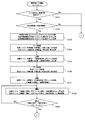
- the procedure of the control process performed by the control device 1a will be described with reference to FIGS. 6 to 8.
- step S1 the control device 1a performs reception processing of various data. Specifically, the control device 1a receives data of the target hot water temperature (boiling temperature), the target hot water amount (flow rate), and the tap water temperature in the hot water supply cycle, and also the target temperature (preset temperature) in the air conditioning cycle, the target Receive data on air volume and room temperature.
- the target hot water temperature and the target hot water amount of the hot water supply cycle are data input to the control device 1a by setting of the remote controller, and the tap water temperature is data input from the temperature sensor TH1. Further, the target temperature and the target air volume of the air conditioning cycle are data input to the control device 1a from the setting of the remote controller, and the indoor temperature is data input from the temperature sensor TH20.
- control device 1a performs arithmetic processing based on the various data received in step S1.
- control device 1a has a target capacity (Qh) in the hot water supply cycle, a target rotational speed of hot water supply compressor 41, a target discharge temperature (Td) of hot water supply compressor 41, and an input for hot water supply compressor 41.
- a target capacity (Qh) in the hot water supply cycle a target rotational speed of hot water supply compressor 41
- Td target discharge temperature
- Wccomp the target capacity in the air conditioning cycle
- the target number of revolutions of the air conditioning compressor 21 the target evaporation temperature (Te) of the air conditioning refrigerant
- Wccomp input
- step S3 the controller 1a calculates the hot water heat absorption amount from the difference between the target capacity (Qh) of the hot water supply cycle and the compressor input (Whcomp), and also the target capacity (Qc) of the air conditioning cycle and the compressor.
- the air-conditioning heat radiation amount is calculated from the sum of the input (Wccomp).
- step S4 the control device 1a determines whether the hot-water heat absorption amount calculated in step S3 and the air-conditioning heat radiation amount are equal, that is, whether the current state is the third load state.
- step S4 when the difference between the hot water heat absorption amount and the air conditioning heat release amount is within a predetermined numerical range, it is determined that both are equal.
- step S5 the control device 1a performs the process of "control 1 mode".
- the control device 1a opens the two-way valves 35a, 35b, 49b, 49d at the inlet and outlet of the intermediate heat exchanger 23, and the third expansion valve 49a and the third expansion valve 49a at the inlet and outlet of the heat source side heat exchanger 44 for hot water supply
- the fourth expansion valve 49 c is closed, and the first expansion valve 35 c and the second expansion valve 35 d at the inlet and outlet of the air conditioning heat source side heat exchanger 24 are closed. That is, since the hot-water supply heat absorption amount and the air-conditioning heat release amount are equal, the control device 1a makes it possible to perform the cooling operation and the hot-water supply operation using only the intermediate heat exchanger 23.
- step S6 the control device 1a controls the operation of the hot water supply cycle and the air conditioning cycle in accordance with the calculation result in step S2. Specifically, the control device 1a controls the hot water supply compressor 41 so that the target rotational speed is achieved in the hot water supply cycle, stops the hot water supply outdoor fan 45, and achieves the target discharge temperature (Td). The valve opening degree of the hot water supply expansion valve 43 is controlled. Further, the control device 1a controls the air conditioning compressor 21 so as to achieve the target rotation speed in the air conditioning cycle, stops the air conditioning outdoor fan 25, and attains the target evaporation temperature (Te). The valve opening degree of the valve 27 is controlled. Then, in the next step, the process returns as a return, and the process of scheduled operation is ended.
- the control device 1a controls the hot water supply compressor 41 so that the target rotational speed is achieved in the hot water supply cycle, stops the hot water supply outdoor fan 45, and achieves the target discharge temperature (Td).
- the valve opening degree of the hot water supply expansion valve 43 is controlled.
- step S7 determines whether hot-water supply heat-absorption amount is less than the air-conditioning heat release.
- the control device 1a performs the process of "control 2 mode" and the hot water supply heat storage amount is If it is determined that the air-conditioning radiation amount is exceeded, that is, if the current state is the second load state, the control device 1a performs the process of "control 3 mode".
- step S8 the control device 1a opens the two-way valve 35a, 35b, 49b, 49d at the inlet / outlet of the intermediate heat exchanger 23.
- the third expansion valve 49a and the fourth expansion valve 49c at the inlet and outlet of the heat exchanger 44 are closed, and the first expansion valve 35c and the second expansion valve 35d at the inlet and outlet of the heat source side heat exchanger 24 for air conditioning are opened.
- control unit 1a since the control unit 1a has a larger amount of air conditioning heat radiation than the amount of heat absorption of hot water, the controller 1a dissipates the difference heat corresponding to the difference between the amount of heat of air conditioning and the heat absorption of hot water from the heat source side heat exchanger 24 for air conditioning to the atmosphere.
- the cooling operation and the hot water supply operation can be performed.
- step S9 the control device 1a performs reception processing of various data. Specifically, the control device 1a receives the data of the heat supply heat absorption amount and the air conditioning radiation amount calculated in step S3 and the data of the outside air temperature inputted from the temperature sensor TH19. Then, the process proceeds to step S10, and the control device 1a determines the target evaporation temperature (Te) of the hot water supply refrigerant in the hot water supply cycle and the target condensation temperature (Tc) of the air conditioning refrigerant in the air conditioning cycle based on the various data received in step S9. Calculate).
- Te target evaporation temperature
- Tc target condensation temperature
- step S11 the control device 1a controls the operation of the hot water supply cycle and the air conditioning cycle according to the calculation result in step S9. Specifically, the control device 1a controls the hot water supply compressor 41 so that the target rotational speed is achieved in the hot water supply cycle, stops the hot water supply outdoor fan 45, and achieves the target evaporation temperature (Te). The valve opening degree of the hot water supply expansion valve 43 is controlled. Further, in the air conditioning cycle, the control device 1a controls the air conditioning compressor 21 to achieve the target rotation speed, and controls the rotation speed of the air conditioning outdoor fan 25 to achieve the target condensation temperature (Tc). The valve opening degree of the air conditioning expansion valve 27 is controlled so as to reach the target condensation temperature (Tc).
- step S12 the controller 1a determines whether the target evaporation temperature (Te) of the hot water supply cycle has been reached.
- the process proceeds to Step S13, and the control device 1a determines whether or not the target condensing temperature (Tc) of the air conditioning cycle is reached.
- the process proceeds to Step S15, and the control device 1a confirms whether the operation of the hot water supply cycle has become the target hot water supply capacity (Qh) and the operation of the air conditioning cycle is the target air conditioning capacity Check if it is (Qc). And when it determines with Yes by step S15, it becomes a return by the following step, and complete
- step S12 when it is determined No in step S12, the process returns to step S11, and the control device 1a adjusts the valve opening degree of the hot water supply expansion valve 43 until the target evaporation temperature (Te) of the hot water supply cycle is reached.
- the control device 1a adjusts the valve opening degree of the hot water supply expansion valve 43 until the target evaporation temperature (Te) of the hot water supply cycle is reached.
- the hot water supply cycle with a small amount of heat is controlled to the target evaporation temperature (Te). Then, if it is determined No in step S13, the opening degrees of the first expansion valve 35c and the second expansion valve 35d are adjusted (slightly closed) in step S14.
- step S11 the process returns to step S11, and the control device 1a adjusts the opening degree of the first expansion valve 35c and the second expansion valve 35d until the target condensing temperature (Tc) of the air conditioning cycle is reached.
- the controller 1a controls the operation of the air conditioning cycle after the hot water supply cycle reaches the target evaporation temperature (Te).
- the order of control for setting the air conditioning cycle to the target condensation temperature (Tc) is the first to adjust the rotational speed of the air conditioning outdoor fan 25 (step S11), and the air conditioning cycle is still the target condensation temperature If (Tc) does not hold (No in step S14), the opening degree of the first expansion valve 35c and the second expansion valve 35d at the inlet / outlet of the heat source side heat exchanger 24 for air conditioning is additionally adjusted. ing. That is, even if the control device 1a controls the number of rotations of the outdoor fan 25 for air conditioning, the difference between the heat exchange amount of the heat source side heat exchanger 24 for air conditioning and the hot water heat absorption amount obtained in step S3 and the air conditioning heat radiation amount. If the difference between the heat quantity difference and the equivalent heat quantity is outside the predetermined range, the opening degrees of the first expansion valve 35c and the second expansion valve 35d are adjusted to compensate for the difference, and the heat quantity to be exchanged is It is controlled to keep balance.
- step S16 the control device 1a opens the two-way valve 35a, 35b, 49b, 49d at the inlet / outlet of the intermediate heat exchanger 23
- the third expansion valve 49a and the fourth expansion valve 49c at the inlet and outlet of the heat exchanger 44 are opened, and the first expansion valve 35c and the second expansion valve 35d at the inlet and outlet of the air conditioning heat source side heat exchanger 24 are closed. That is, since the amount of heat absorbed by the hot water supply is larger than the amount of heat released from the air conditioning, the control device 1a absorbs heat from the air at the heat source side heat exchanger 44 for heat supply. While the cooling operation and the hot water supply operation can be performed.
- step S17 the control device 1a performs various data reception processing. Specifically, the control device 1a receives the data of the heat supply heat absorption amount and the air conditioning radiation amount calculated in step S3 and the data of the outside air temperature inputted from the temperature sensor TH19. Then, the process proceeds to step S18, and the control device 1a determines the target evaporation temperature (Te) of the hot water supply refrigerant in the hot water supply cycle and the target condensation temperature (Tc) of the air conditioning refrigerant in the air conditioning cycle based on the various data received in step S17. Calculate).
- Te target evaporation temperature
- Tc target condensation temperature
- step S19 the control device 1a controls the operation of the hot water supply cycle and the air conditioning cycle according to the calculation result in step S18.
- the control device 1a controls the hot water supply compressor 41 to achieve the target rotational speed, and controls the rotational speed of the hot water supply outdoor fan 45 to achieve the target evaporation temperature (Te).
- the degree of opening of the hot water supply expansion valve 43 is controlled so as to achieve the target evaporation temperature (Te).
- the control device 1a controls the air conditioning compressor 21 so as to achieve the target rotational speed in the air conditioning cycle, stops the air conditioning outdoor fan 25, and attains the target condensation temperature (Tc).
- the valve opening degree of the valve 27 is controlled.
- step S20 the controller 1a determines whether the target condensing temperature (Tc) of the air conditioning cycle has been reached.
- the process proceeds to Step S21, and the control device 1a determines whether or not the target evaporation temperature (Te) of the hot water supply cycle is reached.
- the process proceeds to Step S23, and the control device 1a confirms whether the operation of the hot water supply cycle has become the target hot water supply capacity (Qh) and the operation of the air conditioning cycle is the target air conditioning capacity Check if it is (Qc). And when it determines with Yes by step S23, it becomes a return by the following step, and complete
- step S20 when it is determined No in step S20, the process returns to step S19, and the control device 1a adjusts the valve opening degree of the air conditioning expansion valve 27 until the target condensing temperature (Tc) of the air conditioning cycle is reached.
- Tc target condensing temperature
- the air-conditioning cycle having a small heat amount is controlled to be the target condensation temperature (Tc).
- the opening degrees of the third expansion valve 49a and the fourth expansion valve 49c are adjusted in step S22 (slightly closed).
- step S19 the control device 1a adjusts the opening degree of the third expansion valve 49a and the fourth expansion valve 49c until the target evaporation temperature (Te) of the hot water supply cycle is reached.
- the control device 1a controls the operation of the hot water supply cycle after the air conditioning cycle reaches the target condensation temperature (Tc).
- the order of control for setting the hot water supply cycle to the target evaporation temperature (Te) is the first to adjust the rotation speed of the outdoor fan 45 for hot water supply (step S19), and the hot water supply cycle is still the target evaporation temperature If (Te) does not hold (No in step S21), the opening degree of the third expansion valve 49a and the fourth expansion valve 49c at the inlet / outlet of the heat source side heat exchanger for hot water supply 44 is additionally adjusted. ing.
- the control device 1a controls the number of rotations of the hot water supply outdoor fan 45, the difference between the heat exchange amount of the hot water supply heat source side heat exchanger 44 and the hot water heat absorption amount obtained in step S3 and the air conditioning heat radiation amount If the difference between the heat quantity difference and the equivalent heat quantity is outside the predetermined range, the opening degrees of the third expansion valve 49a and the fourth expansion valve 49d are adjusted to compensate for the difference, and the heat quantity to be exchanged is It is controlled to keep balance.
- control 1 mode will be described with reference to FIG.
- the first expansion valve 35c, the second expansion valve 35d, the third expansion valve 49a, and the fourth expansion valve 49c are closed, and the air conditioning outdoor fan 25 and the hot water supply outdoor fan 45 are stopped. .
- the high temperature and high pressure gas refrigerant discharged from the discharge port 21 b of the air conditioning compressor 21 flows into the intermediate heat exchanger 23 through the four-way valve 22.
- the high temperature and high pressure gas refrigerant flowing in the intermediate heat exchanger 23 dissipates heat to the low temperature hot water supply refrigerant flowing in the intermediate heat exchanger 23, condenses and liquefies.
- the high pressure liquid refrigerant is decompressed and expanded by the air conditioning expansion valve 27 adjusted to a predetermined opening degree, and becomes a low-temperature low pressure gas-liquid two-phase refrigerant. It flows into the exchanger 28.
- the gas-liquid two-phase refrigerant flowing in the air-conditioning use-side heat exchanger 28 absorbs heat from the high-temperature cold water flowing in the air-conditioning cold / hot water circulation circuit 8 and evaporates to become a low-pressure gas refrigerant.
- the low pressure gas refrigerant flows into the suction port 21a of the air conditioning compressor 21 through the four-way valve 22, and is compressed again by the air conditioning compressor 21 to be a high temperature high pressure gas refrigerant.
- the cold water radiated to the air conditioning refrigerant flowing through the air conditioning use-side heat exchanger 28 passes through the air conditioning cold and hot water piping 55a by driving the air conditioning hot and cold water circulation pump 52 It flows into the heat exchanger 61.
- the indoor heat exchanger 61 heat exchange is performed between the cold water in the air conditioning cold and hot water circulation circuit 8 and the high temperature air in the house 60, and the air of the house 60 is cooled. That is, the room of the house 60 is cooled. At this time, the cold water flowing through the indoor heat exchanger 61 absorbs heat from the air in the house 60 and is heated.
- the heated cold water flows through the air conditioning cold and hot water pipes 55b and 55c by the air conditioning cold and hot water circulation pump 52, and flows through the air conditioning refrigerant circuit 5 while flowing through the air conditioning use side heat exchanger 28 again. It exchanges heat with the refrigerant and is cooled.
- the gas refrigerant compressed by the hot water supply compressor 41 and brought to a high temperature and high pressure flows into the hot water supply use side heat exchanger 42.
- the high-temperature and high-pressure gas refrigerant flowing in the hot water use side heat exchanger 42 dissipates heat to the water flowing in the hot water supply flow path 9, condenses and liquefies.
- the liquefied high-pressure refrigerant flows through the hot-water supply refrigerant tank 46 and is decompressed and expanded by the hot-water supply expansion valve 43 adjusted to a predetermined opening degree, and becomes a low-temperature low-pressure gas-liquid two-phase refrigerant.
- the gas-liquid two-phase refrigerant absorbs heat from the high temperature air-conditioning refrigerant flowing through the intermediate heat exchanger 23, evaporates, and becomes a low pressure gas refrigerant.
- the low pressure gas refrigerant flows into the suction port 41a of the hot water supply compressor 41, is compressed again by the hot water supply compressor 41, and becomes a high temperature and high pressure gas refrigerant.
- the water flowing into the water supply port 78 flows in the hot water supply pipe 72 and is guided to the hot water use side heat exchanger 42.
- the water that has flowed into the hot water use side heat exchanger 42 absorbs heat from the hot water supply refrigerant flowing through the hot water supply refrigerant circuit 6 in the hot water use side heat exchanger 42 and changes to high temperature hot water.
- the hot water flows in the hot water supply pipe 73, is stored in the hot water storage tank 70, and is guided from the hot water supply port 79 to the hot water supply load side according to the user's request.
- control 1 mode only the intermediate heat exchanger 23 is used without using the heat source side heat exchanger 24 for air conditioning and the heat source side heat exchanger 44 for hot water supply because the hot water heat absorption amount and the air conditioning heat radiation amount are equal.
- the efficiency of the entire system can be improved without wasting the exhaust heat of the air conditioning cycle.
- control 2 mode will be described with reference to FIG.
- the first expansion valve 35c and the second expansion valve 35d are open, but the third expansion valve 49a and the fourth expansion valve 49c are closed. Further, although the air conditioning outdoor fan 25 is rotating, the hot water supplying outdoor fan 45 is stopped.
- the high temperature and high pressure gas refrigerant discharged from the discharge port 21b of the air conditioning compressor 21 flows through the four-way valve 22 into the intermediate heat exchanger 23 and the air conditioning heat source side heat exchanger 24.
- the high temperature / high pressure gas refrigerant flowing in the intermediate heat exchanger 23 dissipates heat to the low temperature hot water supply refrigerant flowing in the intermediate heat exchanger 23, condenses and condenses, and also the high temperature flowing in the air conditioning heat source side heat exchanger 24
- the high-pressure gas refrigerant releases heat to the atmosphere sent from the air conditioning outdoor fan 25, condenses, and condenses.
- the high pressure liquid refrigerant After flowing through the air conditioning refrigerant tank 26, the high pressure liquid refrigerant is decompressed and expanded by the air conditioning expansion valve 27 adjusted to a predetermined opening degree, and becomes a low-temperature low pressure gas-liquid two-phase refrigerant. It flows into the exchanger 28.
- the gas-liquid two-phase refrigerant flowing in the air-conditioning use-side heat exchanger 28 absorbs heat from the high-temperature cold water flowing in the air-conditioning cold / hot water circulation circuit 8 and evaporates to become a low-pressure gas refrigerant.
- the low pressure gas refrigerant flows into the suction port 21a of the air conditioning compressor 21 through the four-way valve 22, and is compressed again by the air conditioning compressor 21 to be a high temperature high pressure gas refrigerant.
- the gas refrigerant compressed by the hot water supply compressor 41 and brought to a high temperature and high pressure flows into the hot water supply use side heat exchanger 42.
- the high-temperature and high-pressure gas refrigerant flowing in the hot water use side heat exchanger 42 dissipates heat to the water flowing in the hot water supply flow path 9, condenses and liquefies.
- the liquefied high-pressure refrigerant flows through the hot-water supply refrigerant tank 46 and is decompressed and expanded by the hot-water supply expansion valve 43 adjusted to a predetermined opening degree, and becomes a low-temperature low-pressure gas-liquid two-phase refrigerant.
- the gas-liquid two-phase refrigerant absorbs heat from the high temperature air-conditioning refrigerant flowing through the intermediate heat exchanger 23, evaporates, and becomes a low pressure gas refrigerant.
- the low pressure gas refrigerant flows into the suction port 41a of the hot water supply compressor 41, is compressed again by the hot water supply compressor 41, and becomes a high temperature and high pressure gas refrigerant.
- the difference heat amount corresponding to the difference between the air-conditioning heat release amount and the hot-water heat absorption amount is Heat is dissipated.
- the hot water supply heat source side heat exchanger 44 is not used in the hot water supply cycle. That is, in the hot water supply cycle, it is possible to operate the air conditioning and hot water supply system using the exhaust heat of the air conditioning cycle for the hot water supply cycle using only the intermediate heat exchanger 23. Therefore, according to the control 2 mode, the efficiency of the entire system can be improved without wasting the exhaust heat of the air conditioning cycle.
- control 3 mode will be described with reference to FIG.
- the first expansion valve 35c and the second expansion valve 35d are closed, but the third expansion valve 49a and the fourth expansion valve 49c are open. Further, although the air conditioning outdoor fan 25 is stopped, the hot water supply outdoor fan 45 is rotating.
- the high temperature and high pressure gas refrigerant discharged from the discharge port 21 b of the air conditioning compressor 21 flows into the intermediate heat exchanger 23 through the four-way valve 22.
- the high temperature and high pressure gas refrigerant flowing in the intermediate heat exchanger 23 dissipates heat to the low temperature hot water supply refrigerant flowing in the intermediate heat exchanger 23, condenses and liquefies.
- the high pressure liquid refrigerant is decompressed and expanded by the air conditioning expansion valve 27 adjusted to a predetermined opening degree, and becomes a low-temperature low pressure gas-liquid two-phase refrigerant. It flows into the exchanger 28.
- the gas-liquid two-phase refrigerant flowing in the air-conditioning use-side heat exchanger 28 absorbs heat from the high-temperature cold water flowing in the air-conditioning cold / hot water circulation circuit 8 and evaporates to become a low-pressure gas refrigerant.
- the low pressure gas refrigerant flows into the suction port 21a of the air conditioning compressor 21 through the four-way valve 22, and is compressed again by the air conditioning compressor 21 to be a high temperature high pressure gas refrigerant.
- the gas refrigerant compressed by the hot water supply compressor 41 and brought to a high temperature and high pressure flows into the hot water supply use side heat exchanger 42.
- the high-temperature and high-pressure gas refrigerant flowing in the hot water use side heat exchanger 42 dissipates heat to the water flowing in the hot water supply flow path 9, condenses and liquefies.
- the liquefied high-pressure refrigerant flows through the hot-water supply refrigerant tank 46 and is decompressed and expanded by the hot-water supply expansion valve 43 adjusted to a predetermined opening degree, and becomes a low-temperature low-pressure gas-liquid two-phase refrigerant.
- the gas-liquid two-phase refrigerant is sent from the high temperature air conditioning refrigerant flowing through the intermediate heat exchanger 23 and the outdoor fan 45 for hot water supply while flowing through the intermediate heat exchanger 23 and the heat source side heat exchanger for hot water supply 44. It absorbs heat from the atmosphere and evaporates to become a low pressure gas refrigerant.
- the low pressure gas refrigerant flows into the suction port 41a of the hot water supply compressor 41, is compressed again by the hot water supply compressor 41, and becomes a high temperature and high pressure gas refrigerant.
- the air conditioning heat source side heat exchanger 24 is not used. That is, the exhaust heat of the air conditioning cycle dissipates heat to the hot water supply cycle through only the intermediate heat exchanger 23. In other words, the exhaust heat of the air conditioning cycle is all used for the hot water supply cycle. Therefore, according to this control 3 mode, the efficiency of the entire system can be improved without wasting the exhaust heat of the air conditioning cycle.
- the two-way valves 35a, 35b are open, the two-way valves 49b, 49d are closed, and the expansion valves 35c, 35d, 49a, 49c are open. Therefore, the hot water supply refrigerant does not flow to the intermediate heat exchanger 23, but flows only to the hot water supply heat source side heat exchanger 44, and the air conditioning refrigerant is both the intermediate heat exchanger 23 and the air conditioning heat source side heat exchanger 24. Flow to the
- the high temperature and high pressure gas refrigerant discharged from the discharge port 21 b of the air conditioning compressor 21 flows through the four-way valve 22 into the air conditioning use side heat exchanger 28.
- the high-temperature and high-pressure gas refrigerant flowing in the air-conditioning use side heat exchanger 28 dissipates heat to the hot water flowing in the air-conditioning hot and cold water circuit 8, condenses, and liquefies.
- the high pressure liquid refrigerant is decompressed and expanded by the air conditioning expansion valve 27 adjusted to a predetermined opening degree to become a low temperature low pressure gas-liquid two-phase refrigerant, and passes through the air conditioning refrigerant tank 26 to perform heat source side heat exchange for air conditioning Flows into the heat exchanger 24 and the intermediate heat exchanger 23.
- the gas-liquid two-phase refrigerant flowing in the air-conditioning heat source side heat exchanger 24 absorbs heat from the air sent from the air-conditioning outdoor fan 25, evaporates, and becomes a low-pressure gas refrigerant.
- the gas-liquid two-phase refrigerant flowing in the intermediate heat exchanger 23 absorbs a little heat from the plate on which the hot-water supply refrigerant is not flowing, and evaporates to become a low-pressure gas refrigerant.
- the low pressure gas refrigerant flows into the suction port 21a of the air conditioning compressor 21 through the four-way valve 22, and is compressed again by the air conditioning compressor 21 to be a high temperature high pressure gas refrigerant.
- the gas refrigerant compressed by the hot water supply compressor 41 and brought to a high temperature and high pressure flows into the hot water supply use side heat exchanger 42.
- the high-temperature and high-pressure gas refrigerant flowing in the hot water use side heat exchanger 42 dissipates heat to the water flowing in the hot water supply flow path 9, condenses and liquefies.
- the liquefied high-pressure refrigerant flows through the hot-water supply refrigerant tank 46 and is decompressed and expanded by the hot-water supply expansion valve 43 adjusted to a predetermined opening degree, and becomes a low-temperature low-pressure gas-liquid two-phase refrigerant.
- the gas-liquid two-phase refrigerant absorbs heat from the air sent from the outdoor fan for hot water supply 45 and evaporates to become a low pressure gas refrigerant. Then, the low pressure gas refrigerant leaving the heat source side heat exchanger for hot water supply 44 flows into the suction port 41a of the hot water supply compressor 41, is compressed again by the hot water supply compressor 41, and becomes a high temperature high pressure gas refrigerant.
- a major feature of the strong heating operation mode is that the intermediate heat exchanger 23 in which the hot water supply refrigerant is not flowing is used as an evaporator in the air conditioning cycle. That is, the feature of this mode is that the heat is absorbed also from the heat transfer surface of the empty plate and the capacity of the heating operation by the refrigerant circuit 5 for air conditioning is enhanced even if the content is a little. Therefore, when the room of the house 60 is difficult to warm up sufficiently in winter, it is effective to operate in the strong heating operation mode.
- step S101 the control device 1a determines whether or not the tank temperature input from the temperature sensor TH21 is equal to or less than a temperature at which hot water can be supplied. In the case of Yes in step S101, the control device 1a determines in step S102 whether the hot water supply heat absorption amount is larger than the air conditioning heat release amount.
- step S103 If the amount of heat absorbed by the hot water supply is larger than the amount discharged from the air conditioning, the process proceeds to step S103, and the control device 1a opens the two-way valves 35a, 35b, 49b, and 49d at the inlet and outlet of the intermediate heat exchanger 23, and The third expansion valve 49a and the fourth expansion valve 49c at the inlet and outlet of the heat exchanger 44 are opened, and the first expansion valve 35c and the second expansion valve 35d at the inlet and outlet of the air conditioning heat source side heat exchanger 24 are closed. That is, since the amount of heat absorbed by the hot water supply is larger than the amount of heat released from the air conditioning, the control device 1a absorbs heat from the air at the heat source side heat exchanger 44 for heat supply. While the cooling operation and the hot water supply operation can be performed.
- step S104 the control device 1a performs reception processing of various data. Specifically, the control device 1a receives the target hot water amount, the target hot water temperature, the tap water temperature (input from the temperature sensor TH1), and the outdoor temperature (input from the temperature sensor TH19) in the hot water supply cycle. Furthermore, the control device 1a receives a target temperature, a target air volume, an indoor temperature (input from the temperature sensor TH20), and an outdoor temperature (input from the temperature sensor TH19) in the air conditioning cycle.
- step S105 the control device 1a determines the target capacity in the air conditioning cycle, the number of rotations of the air conditioning compressor 21, the number of rotations of the air conditioning outdoor fan 25, the compression for air conditioning The discharge temperature of the machine 21, the power consumption of the air conditioning compressor 21, and the heat release amount are calculated.
- step S106 the control device 1a receives data of the heat release amount of the air conditioning cycle calculated in step S105, and receives data of the target hot water amount, target hot water temperature, tap water temperature, and outdoor temperature in the hot water supply cycle. .
- step S107 the control device 1a sets the target capacity in the hot water supply cycle, the rotational speed of the hot water supply compressor 41, the rotational speed of the hot water supply outdoor fan 45, the discharge temperature of the hot water supply compressor 41, and the hot water supply The power consumption of the compressor 21 is calculated.
- step S108 the control device 1a controls the operation of the hot water supply cycle and the air conditioning cycle according to the calculation result performed earlier.
- control device 1a controls the hot water supply compressor 41 so as to achieve the target rotational speed in the hot water supply cycle, and controls the rotational speed of the hot water supply outdoor fan 45 so as to achieve the target rotational speed.
- the valve opening degree of the hot water supply expansion valve 43 is controlled to achieve the target capacity.
- control device 1a controls the air conditioning compressor 21 so as to achieve the target rotation speed in the air conditioning cycle, stops the air conditioning outdoor fan 25 and also operates the valve for the air conditioning expansion valve 27 to achieve the target capacity. Control the opening degree.
- step S109 the control device 1a determines whether or not the hot water supply cycle and the air conditioning cycle each have a target capacity. When it is judged as Yes at Step S109, it progresses to Step S110, and it is judged whether control device 1a needs hot-water supply water. If it is necessary to add water, the process proceeds to step S111, where the controller 1a closes the tank return valve (not shown) and opens the water circuit valve (not shown) to perform water addition. On the other hand, if No in step S110, the process proceeds to step S112, where the control device 1a closes the tank return valve (not shown) and closes the water circuit valve (not shown). In other words, do not add water.
- step S113 hot water is supplied from the faucet on the hot water supply load side (not shown) via the hot water supply port 79. Then, in the next step, the process returns as a return and the process of the instantaneous heating operation mode is exited. If No in step S109, the process returns to step S108, and if it is determined No in step S101 and if it is determined No in step S102, the process returns as a return to the processing of the instantaneous heating operation mode Get out of.
- step S201 the control device 1a determines whether the cooling request is equal to or more than the maximum capacity of the cooling only operation. In the case of Yes in step S201, the control device 1a determines in step S202 whether the amount of heat released by air conditioning is larger than the amount of heat absorbed by the hot water supply.
- step S203 the control device 1a opens the two-way valve 35a, 35b, 49b, 49d at the inlet / outlet of the intermediate heat exchanger 23
- the third expansion valve 49a and the fourth expansion valve 49c at the inlet and outlet of the heat exchanger 44 are closed, and the first expansion valve 35c and the second expansion valve 35d at the inlet and outlet of the heat source side heat exchanger 24 for air conditioning are opened.
- control unit 1a since the control unit 1a has a larger amount of air conditioning heat dissipation than the amount of heat absorption of hot water, it dissipates the difference heat corresponding to the difference between the amount of heat absorption of hot water and the heat release of air conditioning from the heat source side heat exchanger 24 for air conditioning to the atmosphere.
- the cooling operation and the hot water supply operation can be performed.
- step S204 the control device 1a performs reception processing of various data. Specifically, the control device 1a receives the target hot water amount, the target hot water temperature, the tap water temperature (input from the temperature sensor TH1), and the outdoor temperature (input from the temperature sensor TH19) in the hot water supply cycle. Furthermore, the control device 1a receives target temperature, target air volume, indoor temperature (input from the temperature sensor TH20) and outdoor temperature (input from the temperature sensor TH19) data in the air conditioning cycle. Then, the process proceeds to step S205, and the control device 1a determines the target capacity in the air conditioning cycle, the discharge temperature of the air conditioning compressor 21, the power consumption of the air conditioning compressor 21, and the heat radiation amount based on the various data received in step S204. Calculate
- step S206 the control device 1a receives data of the heat release amount of the air conditioning cycle calculated in step S205, and receives data of the target hot water amount, target hot water temperature, tap water temperature, and outdoor temperature in the hot water supply cycle. .
- step S207 the control device 1a sets the target capacity in the hot water supply cycle, the rotational speed of the hot water supply compressor 41, the rotational speed of the hot water supply outdoor fan 45, the discharge temperature of the hot water supply compressor 41, and the hot water supply The power consumption of the compressor 21 is calculated.
- step S208 the control device 1a controls the operation of the hot water supply cycle and the air conditioning cycle according to the calculation result performed earlier.
- control device 1a controls the hot water supply compressor 41 so that the target rotational speed is achieved in the hot water supply cycle, and controls the hot water supply outdoor fan 45 to stop, and the hot water supply so as to achieve the target capacity.
- Valve opening degree of the expansion valve 43 is controlled.
- the control device 1a controls the air conditioning compressor 21 so as to attain a predetermined number of revolutions, and controls the rotation of the air conditioning outdoor fan 25 so as to achieve a predetermined number of revolutions.
- the valve opening degree of the air conditioning expansion valve 27 is controlled so that
- the predetermined number of rotations of the air conditioning compressor 21 is set to the maximum number of used rotations, it is not limited to the maximum number of rotations.
- predetermined number of rotations of the air conditioning outdoor fan 25 is also set to the maximum number of used rotations, it is not limited to the maximum number of rotations.
- step S209 the control device 1a determines whether or not the hot water supply cycle and the air conditioning cycle each have a target capacity.
- the process returns to the next step and the process of the rapid cooling operation mode is exited. If No in step S209, the process returns to step S208, and if it is determined No in step S201, and if it is determined No in step S202, the process returns as a return to the rapid cooling operation mode processing. Get out.
- the load of the hot water supply operation is not dissipated to the atmosphere via the heat source side heat exchanger 24 for air conditioning, but the difference heat amount corresponding to the difference between the air conditioning heat release amount and the hot water supply heat absorption amount.
- the cooling operation and the hot water supply operation are performed by heat exchange only with the intermediate heat exchanger 23 without using the heat source side heat exchanger 24 for air conditioning. It makes it possible. The control will be described below.
- step S301 the control device 1a determines whether the air conditioning heat release amount is larger than the hot water supply heat absorption amount. If the air-conditioning radiation amount is larger than the hot-water heat absorption amount, the process proceeds to step S302, and the control device 1a opens the two-way valves 35a, 35b, 49b, and 49d at the inlet and outlet of the intermediate heat exchanger 23, and the heat source side for hot-water supply
- the third expansion valve 49a and the fourth expansion valve 49c at the inlet and outlet of the heat exchanger 44 are closed, and the first expansion valve 35c and the second expansion valve 35d at the inlet and outlet of the heat source side heat exchanger 24 for air conditioning are closed.
- step S303 the control device 1a performs reception processing of various data. Specifically, the control device 1a receives the target hot water amount, the target hot water temperature, the tap water temperature (input from the temperature sensor TH1), and the outdoor temperature (input from the temperature sensor TH19) in the hot water supply cycle. Furthermore, the control device 1a receives data of a target temperature, a target air volume, an indoor temperature (input from the temperature sensor TH20), and an outdoor temperature (input from the temperature sensor TH19) in the air conditioning cycle.
- step S304 the control device 1a determines the target capacity in the air conditioning cycle, the number of rotations of the air conditioning compressor 21, the number of rotations of the air conditioning outdoor fan 25 and the compression for air conditioning based on the various data received in step S303.
- the discharge temperature of the machine 21, the power consumption of the air conditioning compressor 21, and the heat release amount are calculated.
- step S305 the control device 1a receives data of the heat release amount of the air conditioning cycle calculated in step S304, and receives data of the target hot water amount, target hot water temperature, tap water temperature, and outdoor temperature in the hot water supply cycle.
- step S306 the control device 1a calculates the target capacity in the hot water supply cycle, the rotational speed of the hot water supply compressor 41, the rotational speed of the hot water supply outdoor fan 45, and the discharge temperature of the hot water supply compressor 41.
- step S307 the control device 1a controls the operation of the hot water supply cycle and the air conditioning cycle according to the calculation result performed earlier.
- control device 1a controls the hot water supply compressor 41 so that the target rotational speed is achieved in the hot water supply cycle, and controls the hot water supply outdoor fan 45 to stop, and the hot water supply so as to achieve the target capacity.
- Valve opening degree of the expansion valve 43 is controlled.
- control device 1a controls the air conditioning compressor 21 to achieve the target rotation speed, controls the rotation of the air conditioning outdoor fan 25 to achieve the target rotation speed, and achieves the target capacity.
- the valve opening degree of the air conditioning expansion valve 27 is controlled.
- step S308 the control device 1a determines whether or not the hot water supply cycle and the air conditioning cycle each have a target capacity.
- the process proceeds to step S309, and the control device 1a determines whether the hot water stored in the hot water storage tank 70 satisfies the hot water storage amount (the amount that can be stored in the hot water storage tank 70). Determine When the amount of hot water storage is not satisfied (in the case of No in step S309), the operation is continued as it is (step S310), and the process returns to step S309.
- step S311 the control device 1a opens the drain valve 71b to discharge the hot water in the hot water storage tank 70 from the drain pipe 71a to the outside.
- step S312 the control device 1a stops the operation of the air conditioning cycle. That is, the control device 1a stops the operation of the air conditioning compressor 21 and the air conditioning outdoor fan 25.
- step S313 the controller 1a opens the third expansion valve 49a and the fourth expansion valve 49c at the inlet and outlet of the heat source side heat exchanger for hot water supply 44, and the two-way valve at the inlet and outlet of the intermediate heat exchanger 23. Close 49b and 49d.
- control device 1a proceeds to step S314 to receive various data. Specifically, the control device 1a determines the current time in the hot water supply cycle, the boiling completion target time, the temperature in the hot water storage tank (input from the temperature sensor TH21), the tap water temperature (input from the temperature sensor TH1), the outdoor temperature Receiving the input from the temperature sensor TH19).
- step S315 the process proceeds to step S315, and based on the various data received in step S314, the control device 1a determines the target capacity in the hot water supply cycle, the number of rotations of the hot water supply compressor 41, the number of rotations of the hot water supply outdoor fan 45, the compression for hot water supply
- the discharge temperature of the machine 21, the power consumption of the hot water supply compressor 21, and the valve opening degree of the hot water supply expansion valve 43 are calculated.
- step S316 the control device 1a controls the operation of the hot water supply cycle according to the calculation result performed earlier. Specifically, in the hot water supply cycle, the control device 1a controls the hot water supply compressor 41 so as to achieve the target rotational speed, and controls the rotation of the hot water supply outdoor fan 45 so as to achieve the target rotational speed.
- step S308 the process returns to step S307, and if NO in step S301, the process returns and the process of the zero exhaust heat operation mode is ended.
- the zero exhaust heat operation mode uses the intermediate heat exchanger 23 as an evaporator in the hot water supply cycle, and the hot water supply operation is performed so as to match the air conditioned heat output even when the air conditioning heat release amount is larger than the hot water heat absorption amount.
- the air conditioning exhaust heat is dissipated to the hot water supply cycle to perform the hot water supply operation.
- the zero exhaust heat operation mode when the hot water in the hot water storage tank 70 is full, the hot water is discharged from the drain pipe 71a to the outside. That is, air conditioning exhaust heat can be discharged to the outside air by using the air conditioning exhaust heat to boil hot water once and then discharging unnecessary hot water to the outside.
- the control device 1a operates the system as it is if the third load state in which the amount of heat supplied by heat supply and the amount of heat released by the air conditioning are equal.
- the control device 1a performs the hot water supply operation so as to be the third load state. Control. Then, the controller 1a performs the hot water supply operation while taking into consideration the current time, the remaining time, and the operation capacity so that the target hot water amount and the target hot water temperature are achieved by the target time, and the controller 1a performs the cooling operation if necessary. Even in the middle, the system is controlled to stop the energy saving operation mode and switch to the normal exhaust heat recovery operation (that is, the scheduled operation mode).
- step S401 the controller 1a determines whether the air conditioning heat radiation amount and the hot water supply heat absorption amount are equal (whether the difference between the air conditioning heat radiation amount and the hot water heat absorption amount is within a predetermined range ) Or not. If it is determined that the amount of heat released from the air conditioning and the amount of heat absorbed by the hot water supply are equal, the process proceeds to step S402, where the control device 1a opens the two-way valves 35a, 35b, 49b, and 49d at the inlet and outlet of the intermediate heat exchanger 23.
- control device 1a is in a state where it is possible to perform the cooling operation and the hot water supply operation using only the intermediate heat exchanger 23, since the hot water supply heat absorption amount and the air conditioning heat release amount are equal.
- step S403 the control device 1a performs reception processing of various data. Specifically, the control device 1a receives data of a target temperature, a target air volume, a target air volume, an indoor temperature (input from the temperature sensor TH20), and an outdoor temperature (input from the temperature sensor TH19) in the air conditioning cycle. Then, the process proceeds to step S404, and the control device 1a determines the target capacity in the air conditioning cycle, the number of revolutions of the air conditioning compressor 21, the number of revolutions of the air conditioning outdoor fan 25, the compression for air conditioning based on various data received in step S403. The discharge temperature of the machine 21, the power consumption of the air conditioning compressor 21, and the heat release amount are calculated.
- step S405 the control device 1a receives data of the heat release amount of the air conditioning cycle calculated in step S404, and receives data of the target hot water amount, target hot water temperature, tap water temperature, and outdoor temperature in the hot water supply cycle. .
- step S406 the control device 1a is used for the target capacity in the hot water supply cycle, the rotational speed of the hot water supply compressor 41, the rotational speed of the hot water supply outdoor fan 45, the discharge temperature of the hot water supply compressor 41, and the hot water supply The power consumption of the compressor 41 is calculated.
- step S407 the control device 1a controls the operation of the hot water supply cycle and the air conditioning cycle according to the calculation result performed earlier.
- control device 1a controls the hot water supply compressor 41 so that the target rotational speed is achieved in the hot water supply cycle, and controls the hot water supply outdoor fan 45 to stop, and the hot water supply so as to achieve the target capacity.
- Valve opening degree of the expansion valve 43 is controlled.
- control device 1a controls the air conditioning compressor 21 to achieve the target rotation speed in the air conditioning cycle and controls the air conditioning outdoor fan 25 to stop, and the air conditioning expansion valve to achieve the target capacity. Control the valve opening degree of 27.
- step S408 the control device 1a determines whether or not the hot water supply cycle and the air conditioning cycle each have a target capacity.
- the control device 1a stops the operation of the air conditioning cycle and starts the hot water supply independent operation only by the hot water supply cycle. That is, the control device 1a stops the operation of the air conditioning compressor 21 and the air conditioning outdoor fan 25.
- step S410 the controller 1a opens the third expansion valve 49a and the fourth expansion valve 49c at the inlet / outlet of the heat source side heat exchanger for hot water supply 44, and the two-way valve at the inlet / outlet of the intermediate heat exchanger 23. Close 49b and 49d.
- control device 1a proceeds to step S411 and receives various data. Specifically, the control device 1a determines the current time in the hot water supply cycle, the boiling completion target time, the temperature in the hot water storage tank (input from the temperature sensor TH21), the tap water temperature (input from the temperature sensor TH1), the outdoor temperature Receiving the input from the temperature sensor TH19). Then, the process proceeds to step S412, and the control device 1a determines the target capacity in the hot water supply cycle, the number of rotations of the hot water supply compressor 41, the number of rotations of the hot water supply outdoor fan 45, the compression for hot water supply The discharge temperature of the machine 21, the power consumption of the hot water supply compressor 21, and the valve opening degree of the hot water supply expansion valve 43 are calculated.
- step S413 the control device 1a controls the operation of the hot water supply cycle according to the calculation result performed earlier. Specifically, in the hot water supply cycle, the control device 1a controls the hot water supply compressor 41 so as to achieve the target rotational speed, and controls the rotation of the hot water supply outdoor fan 45 so as to achieve the target rotational speed. Then, in the next step, it becomes a return and exits the processing of the energy saving operation mode. If NO in step S408, the process returns to step S407, and if NO in step S401, the process returns and the process of the energy saving operation mode is exited. As described above, since the energy saving operation mode is operated while utilizing all of the air conditioning exhaust heat for the hot water supply operation, it can be said that the energy saving operation mode is an operation mode excellent in energy saving performance.
- the air conditioning and hot water supply system when the air conditioning heat release amount is larger than the hot water supply heat absorption amount, the intermediate heat exchanger 23 and for air conditioning in the air conditioning cycle. It is possible to perform the cooling operation while radiating heat in the heat source side heat exchanger 24 and perform the hot water supply operation while absorbing heat from the intermediate heat exchanger 23 in the hot water supply cycle.
- the cooling operation is performed while radiating heat in the intermediate heat exchanger 23 in the air-conditioning cycle, and in the hot-water supply cycle, the intermediate heat exchanger 23 and the heat source side heat exchange for hot water supply It is possible to perform the hot water supply operation while absorbing heat from the heater 44.
- the cooling operation and the hot water supply operation may be performed while the heat exchange between the air conditioning cycle and the hot water supply cycle is performed via the intermediate heat exchanger 23 it can.
- the air conditioning and hot water supply system according to the present embodiment, it is possible to perform the cooling operation and the hot water supply operation according to the magnitude relation between the air conditioning heat release amount and the hot water supply heat absorption amount.
- the air conditioning and hot water supply system according to the present embodiment, only the differential heat quantity corresponding to the difference between the air conditioning heat release amount and the hot water supply heat absorption amount is used as the heat source side heat exchanger 24 for air conditioning or the heat source side heat exchanger 44 for hot water supply. Since the system is controlled to exchange heat via the system, the efficiency of the entire system is improved.
- various operation requests can be answered and convenience is enhanced.
- the intermediate heat exchanger 23 and the heat source side heat exchanger 44 for hot water supply are connected in series, and intermediate heat exchange It is characterized in that the unit 23 and the heat source side heat exchanger 24 for air conditioning are connected in series.
- the refrigerant pipe between the four-way valve 22 and the air-conditioning expansion valve 27 in the air-conditioning refrigerant circuit 5 from the four-way valve 22 side, the two-way valve 35a, the intermediate heat exchanger 23, and the two-way valve
- the first expansion valve 35c, the heat source side heat exchanger 24 for air conditioning, the second expansion valve 35d, and the refrigerant tank 26 for air conditioning are incorporated in series in this order.
- an air conditioning bypass pipe 101 for bypassing the intermediate heat exchanger 23 is connected to the air conditioning refrigerant circuit 5, and an air conditioning bypass valve 35 e is attached to the air conditioning bypass pipe 101.
- the 49b, the fourth expansion valve 49c, the heat source side heat exchanger for hot water supply 44, and the third expansion valve 49a are incorporated in series in this order.
- a hot water supply bypass pipe 201 for bypassing the intermediate heat exchanger 23 is connected to the hot water supply refrigerant circuit 6, and a hot water supply bypass valve 49e is attached to the hot water supply bypass pipe 201.
- the two-way valves 35a, 35b, 49b, 49d, the expansion valves 35c, 35d, 49a, 49c, and the bypass valves 35e, 49e are appropriately controlled by the air conditioning and hot water supply system according to the second embodiment, The same operation as the air conditioning and hot water supply system according to the first embodiment can be performed.
- both the air conditioning heat source side heat exchanger 324 and the hot water supply heat source side heat exchanger 444 have a plurality of paths. It is characterized in that it is configured.
- the air conditioning heat source side heat exchanger 324 provided in the air conditioning refrigerant circuit 5 is formed with a two-pass flow path, and closes one path if necessary, and the other path
- the air conditioning refrigerant can flow only to the In order to return the air conditioning refrigerant remaining in the closed path to the suction side of the air conditioning compressor 21, the air conditioning heat source side heat exchanger 324 and the suction side of the air conditioning compressor 21 return the air conditioning refrigerant. It is connected by a pipe 301.
- the air conditioning refrigerant return pipe 301 is provided with an air conditioning partition valve 301a. When the air conditioning partition valve 301a is opened, the air conditioning refrigerant remaining in the air conditioning heat source side heat exchanger 324 is for air conditioning. It flows through the refrigerant return pipe 301 and returns to the suction side of the air conditioning compressor 21.
- the heat source side heat exchanger for hot water supply 444 provided in the hot water supply refrigerant circuit 6 is formed with a two-pass flow path, and closes one path if necessary, and the hot water supply refrigerant only in the other path
- the structure is capable of In order to return the hot water supply refrigerant remaining in the closed path to the suction side of the hot water supply compressor 41, the hot water supply heat source side heat exchanger 444 and the suction side of the hot water supply compressor 41 return the hot water supply refrigerant. It is connected by piping 401.
- the hot water supply refrigerant return pipe 401 is provided with a hot water supply gate valve 401a.
- the hot water supply refrigerant remaining in the hot water source heat source side heat exchanger 444 is for hot water supply. It flows through the refrigerant return pipe 401 and returns to the suction side of the hot water supply compressor 41.
- the path of the air conditioning heat source side heat exchanger 324 The heat exchange amount of the heat source side heat exchanger 324 for air-conditioning can be adjusted by switching the number by the control device 1a. Further, with regard to the heat source side heat exchanger for hot water supply 441, the heat exchange amount of the heat source side heat exchanger for hot water supply 444 can be adjusted by the control device 1a switching the number of passes. The number of heat exchangers may be appropriately selected in accordance with the specification of the air conditioning and hot water supply system.
- Reference Signs List 1 a control device 5 air conditioning refrigerant circuit 5 a air conditioning refrigerant main circuit 6 hot water supply refrigerant circuit 6 a hot water supply refrigerant main circuit 9 hot water supply flow path 21 air conditioning compressor 22 Four-way valve (flow path switching valve for air conditioning) 24, 24 ... heat source side heat exchanger for air conditioning, 25 ... outdoor fan for air conditioning, 27 ... expansion valve for air conditioning, 28 ... use side heat exchanger for air conditioning, 35 c ...
- first air conditioning refrigerant flow control valve 35 d second expansion valve (second air conditioning refrigerant flow control valve) 41 hot water supply compressor 42 hot water use side heat exchanger 43 Expansion valve for hot water supply, 44, 444: Heat source side heat exchanger for hot water supply, 45: Outdoor fan for hot water supply, 49a: third expansion valve (first refrigerant flow control valve for hot water supply), 49c: fourth expansion valve (second Refrigerant flow control valve for hot water supply), 70 ... hot water storage tank, 71a ... drain piping, 71b ... drain valve, 8 ... water inlet, 79 ... hot water port, 301 ... return refrigerant for air conditioning piping, 301a ... air conditioning gate valve, 401 ... refrigerant hot water return pipe, 401a ... hot water supply gate valve
Landscapes
- Engineering & Computer Science (AREA)
- Physics & Mathematics (AREA)
- Mechanical Engineering (AREA)
- Thermal Sciences (AREA)
- General Engineering & Computer Science (AREA)
- Heat-Pump Type And Storage Water Heaters (AREA)
- Air Conditioning Control Device (AREA)
Abstract
【課題】空調負荷が給湯負荷より小さい場合であっても、空調サイクルからの排熱を利用しながら給湯サイクルの運転を行うことができる空調給湯システムを提供する。 【解決手段】本発明は、冷房運転と暖房運転とを切替えて行う空調用冷媒回路(5)と、給湯運転を行う給湯用冷媒回路(6)と、空調用冷媒回路を循環する空調用冷媒と給湯用冷媒回路を循環する給湯用冷媒との間で熱交換を行う中間熱交換器(23)と、運転の制御を行う制御装置(1a)とを有する空調給湯システムである。制御装置は、冷房運転において空調用冷媒回路が必要とする放熱量および給湯運転において給湯用冷媒回路が必要とする吸熱量を演算する。放熱量が吸熱量より大きければその差分の熱量を空調用熱源側熱交換器から大気に放熱し、吸熱量が放熱量より大きければその差分の熱量を給湯用熱源側熱交換器にて大気から吸熱するよう制御する。
Description
本発明は、空調給湯システムに係り、特に、冷房と暖房とを切替えて行う空調用冷媒回路と給湯を行う給湯用冷媒回路とを中間熱交換器を介して互いに熱交換可能に接続して、空調サイクルと給湯サイクルの二元冷凍サイクルが形成される空調給湯システムに好適なものである。
この種の空調給湯システムとして、例えば特許文献1に示すものがある。この特許文献1には、高温出力を行う高温サイクルと、中温出力または低温出力を行う中温サイクルとを備え、高温サイクルの蒸発器と中温サイクルの凝縮器とが熱交換可能に構成されたシステムが開示されている。この特許文献1の技術によれば、中温サイクルの排熱を高温サイクルで有効に利用できるため、経済的な運転が可能である。
しかしながら、特許文献1に記載の技術では、中温サイクル(空調サイクル)の排熱を高温サイクル(給湯サイクル)の熱源として利用できるのは、中温サイクルの排熱量が高温サイクルの吸熱量より多いときのみである。つまり、空調サイクルの空調負荷が高い場合にしか空調サイクルの排熱を利用した給湯サイクルの運転を行うことができないのである。例えば、断熱性能の高い空間や、居住者が少ないなどで内部発熱の少ない空間を空調する場合や、夜間で外気温度が低下している条件下で空調を行う場合には、空調負荷は低くなることが想定され、環境条件次第では、給湯負荷が空調負荷を上回る可能性があるが、このような場合に、特許文献1に記載の技術では、中温サイクルからの排熱のみでは高温サイクルの要求能力に応じた運転を行うことができないといった課題が残されている。
本発明は、上記した課題を解決するためになされたものであり、その目的は、空調負荷が給湯負荷より小さい場合であっても、空調サイクルからの排熱を利用しながら給湯サイクルの要求能力に応じた運転を行うことができる空調給湯システムを提供することにある。また、空調サイクルの放熱量と給湯サイクルの吸熱量との間で差が生じた場合であっても、その差分の熱量だけを大気と熱交換することにより、システム全体の効率を向上させることができる空調給湯システムを提供することも本発明の別の目的である。
上記目的を達成するために、本発明は、空調用冷媒回路と、給湯用冷媒回路と、前記空調用冷媒回路を循環する空調用冷媒と前記給湯用冷媒回路を循環する給湯用冷媒との間で熱交換を行う中間熱交換器と、運転の制御を行う制御装置とを有する空調給湯システムであって、前記空調用冷媒回路は、空調用圧縮機、空調用流路切替弁、前記中間熱交換器、空調用膨張弁、空調用利用側熱交換器を順次冷媒配管で接続して環状に形成された回路に、大気と前記空調用冷媒との間で熱交換をするための空調用熱源側熱交換器と、前記空調用熱源側熱交換器に大気を送風する空調用室外ファンとを備えて成る空調用熱源側熱交換器ユニットを、前記空調用流路切替弁と前記空調用膨張弁との間で前記中間熱交換器と直列または並列に接続して構成され、前記給湯用冷媒回路は、給湯用圧縮機、給湯用利用側の熱搬送媒体と熱交換を行う給湯用利用側熱交換器、給湯用膨張弁、前記中間熱交換器を順次冷媒配管で接続して環状に形成された回路に、大気と前記給湯用冷媒との間で熱交換をするための給湯用熱源側熱交換器と、前記給湯用熱源側熱交換器に大気を送風する給湯用室外ファンとを備えて成る給湯用熱源側熱交換器ユニットを、前記給湯用圧縮機と前記給湯用膨張弁との間で前記中間熱交換器と直列または並列に接続して構成され、前記制御装置は、前記吸熱量より前記放熱量の方が大きい第1負荷状態の場合には、前記放熱量と前記吸熱量との差に相当する差分熱量を前記空調用熱源側熱交換器ユニットから大気に放熱するよう前記空調用熱源側熱交換器ユニットを制御し、前記放熱量より前記吸熱量の方が大きい第2負荷状態の場合には、前記差分熱量を前記給湯用熱源側熱交換器ユニットにて大気から吸熱するよう前記給湯用熱源側熱交換器ユニットを制御することを特徴とするものである。
本発明によれば、空調用冷媒回路と給湯用冷媒回路とを中間熱交換器を介して熱交換可能に接続すると共に、空調用冷媒回路に空調用熱源側熱交換器を設け、給湯用冷媒回路に給湯用熱源側熱交換器を設けた構成となっているため、第1負荷状態と第2負荷状態の両方の負荷状態において、空調サイクルからの排熱を利用しながら給湯サイクルの要求能力に応じた運転を行うことができる。しかも、本発明では、制御装置が空調側の放熱量と給湯側の吸熱量とを演算し、その差に相当する差分熱量を大気と熱交換するように空調用熱源側熱交換器ユニットおよび給湯用熱源側熱交換器ユニットの動作を制御しているため、空調給湯システム全体の効率を向上することができる。
ここで、本発明において、「空調用熱源側熱交換器ユニットを制御すること」には、空調用室外ファンの回転数を制御すること、第1空調用冷媒流量制御弁および第2空調用冷媒流量制御弁の弁開度を制御すること、空調用熱源側熱交換器のパス数を切替えること、これらを組み合わせて制御すること、その他の空調用熱源側熱交換器の熱交換量を調整するための制御全てが含まれている。また、同様に、「給湯用熱源側熱交換器ユニットを制御すること」には、給湯用室外ファンの回転数を制御すること、第1給湯用冷媒流量制御弁および第2給湯用冷媒流量制御弁の弁開度を制御すること、給湯用熱源側熱交換器のパス数を切替えること、これらを組み合わせて制御すること、その他の給湯用熱源側熱交換器の熱交換量を調整するための制御全てが含まれている。
また、上記構成において、前記空調用熱源側熱交換器ユニットは、前記中間熱交換器と並列に接続され、前記給湯用熱源側熱交換器ユニットは、前記中間熱交換器と並列に接続されるシステムであって、前記空調用熱源側熱交換器ユニットは、前記空調用冷媒の流量を制御するために前記空調用熱源側熱交換器の出入口にそれぞれ設けられた第1空調用冷媒流量制御弁および第2空調用冷媒流量制御弁と、を備え、前記給湯用熱源側熱交換器ユニットは、前記給湯用冷媒の流量を制御するために前記給湯用熱源側熱交換器の出入口にそれぞれ設けられた第1給湯用冷媒流量制御弁および第2給湯用冷媒流量制御弁と、を備えた構成とするのが好ましい。システム全体の制御が簡単だからである。
また、上記構成において、前記制御装置は、前記第1負荷状態の場合には前記空調用室外ファンの回転数を制御し、前記第2負荷状態の場合には前記給湯用室外ファンの回転数を制御する構成とするのが好ましい。熱交換量の調整が簡単だからである。
また、上記構成において、前記制御装置は、前記第1負荷状態において、前記空調用室外ファンの回転数を制御しても、前記空調用熱源側熱交換器ユニットの熱交換量と前記差分熱量との間の差が予め定めた範囲外にある場合には、その差を補うように前記第1空調用冷媒流量制御弁および前記第2空調用冷媒流量制御弁の少なくとも一方の弁開度を調整するよう制御し、前記第2負荷状態において、前記給湯用室外ファンの回転数を制御しても、前記給湯用熱源側熱交換器ユニットの熱交換量と前記差分熱量との間の差が予め定めた範囲外にある場合には、その差を補うように前記第1給湯用冷媒流量制御弁および前記第2給湯用冷媒流量制御弁の少なくとも一方の弁開度を調整するよう制御する構成とするのが好ましい。
この構成によれば、第1負荷状態において、空調用室外ファンの回転数を制御するだけでは、空調用冷媒を中間熱交換器と空調用熱源側熱交換器ユニットに所望の流量に分配して流すことができないような場合であっても、第1空調用冷媒流量制御弁および第2空調用冷媒流量制御弁の少なくとも一方の弁開度を調整する(絞る)ことにより、空調量冷媒が中間熱交換器に流れやすくなるため、所望の流量に分配することができる。よって、空調排熱を無駄なく給湯サイクルに利用できる。また同様に、この構成によれば、第2負荷状態において、第1給湯用冷媒流量制御弁および第2給湯用冷媒流量制御弁の少なくとも一方の弁開度を調整する(絞る)ことにより、給湯用冷媒を中間熱交換器と給湯用熱源側熱交換器ユニットに所望の流量に分配して流すことができる。
また、上記構成において、前記制御装置は、前記第1負荷状態の場合には、前記給湯運転において要求される所定条件を満たすように前記給湯用膨張弁の弁開度を制御した後に、前記冷房運転において要求される所定条件を満たすように前記空調用室外ファンの回転数および前記空調用膨張弁の弁開度の少なくとも一方を制御し、前記第2負荷状態の場合には、前記冷房運転において要求される所定条件を満たすように前記空調用膨張弁の弁開度を制御した後に、前記給湯運転において要求される所定条件を満たすように前記給湯用室外ファンの回転数および前記給湯用膨張弁の弁開度の少なくとも一方を制御する構成とするのが好ましい。この構成によれば、空調サイクルの放熱量と給湯サイクルの吸熱量のうち熱量の小さい方のサイクルを先に制御し、その後、熱量の大きい方のサイクルを制御するようにしているので、熱量のバランスを調整し易いといった利点がある。
また、上記構成において、前記制御装置は、演算された前記放熱量および前記吸熱量と、外気温度とに基づいて、前記冷房運転における目標凝縮温度と、前記給湯運転における目標蒸発温度とを演算し、前記目標凝縮温度を前記冷房運転において要求される前記所定条件に設定し、前記目標蒸発温度を前記給湯運転において要求される前記所定条件に設定する構成とするのが好ましい。
また、上記構成において、前記制御装置は、前記放熱量と前記吸熱量との差が予め定めた範囲内にある第3負荷状態の場合には、前記空調用熱源側熱交換器ユニットおよび前記給湯用熱源側熱交換器ユニットによる大気との熱交換を中止して、前記中間熱交換器を介した前記空調用冷媒回路と前記給湯用冷媒回路との間の熱交換による運転を行うよう制御する構成とするのが好ましい。この構成によれば、中間熱交換器のみを用いて運転ができるので、空調用室外ファンおよび給湯用室外ファンを回転させなくて済む。よって、消費電力の低減が見込める。
また、上記構成において、前記空調用熱源側熱交換器は前記空調用冷媒が流れる複数のパスで構成され、前記給湯用熱源側熱交換器は前記給湯用冷媒が流れる複数のパスで構成され、前記制御装置は、前記第1負荷状態の場合には前記空調用熱源側熱交換器のパス数を切替える制御を行い、前記第2負荷状態の場合には前記給湯用熱源側熱交換器のパス数を切替える制御を行う構成とするのが好ましい。この構成によれば、伝熱面積を小さくして効率良くサイクルを運転することができるうえ、熱交換器に流す冷媒流量を少なくすることができるため冷媒不足を防ぐことができる。
また、上記構成において、前記空調用冷媒回路は、前記空調用熱源側熱交換器から前記空調用圧縮機の吸込側へと前記空調用冷媒を戻すための空調用冷媒戻り配管と、前記空調用冷媒戻り配管に設けられた空調用仕切弁とを備え、前記給湯用冷媒回路は、前記給湯用熱源側熱交換器から前記給湯用圧縮機の吸込側へと前記給湯用冷媒が戻るための給湯用冷媒戻り配管と、前記給湯用冷媒戻り配管に設けられた給湯用仕切弁とを備えた構成とするのが好ましい。この構成によれば、冷媒を圧縮機の吸込側へ戻すことができるので、冷媒不足を防止することができる。
また、上記構成において、前記制御装置は、前記空調用冷媒回路では、前記空調用熱源側熱交換器および前記中間熱交換器を蒸発器として用いた暖房運転を行い、前記給湯用冷媒回路では、前記給湯用熱源側熱交換器を蒸発器として用いた給湯運転を行う強暖房運転モードを備え、前記強暖房運転モードにおいて、前記制御装置は、第1空調用冷媒流量制御弁および第2空調用冷媒流量制御弁を開けて、前記空調用冷媒を前記空調用熱源側熱交換器と前記中間熱交換器の両方に流し、かつ、第1給湯用冷媒流量制御弁および第2給湯用冷媒流量制御弁を開けて、前記給湯用冷媒を前記中間熱交換器に流すことなく前記給湯用熱源側熱交換器に流すように制御する構成とするのが好ましい。
また、上記構成において、前記給湯用利用側熱交換器の入口と前記給湯用利用側の熱搬送媒体の給水口とを配管で接続し、前記給湯用利用側熱交換器の出口と前記給湯用利用側の熱搬送媒体の給湯口とを配管で接続して、前記給湯用利用側の熱搬送媒体が流れる流路を形成し、その流路の前記給湯用利用側熱交換器と前記給湯口の間の位置に前記給湯用利用側の熱搬送媒体を蓄える貯湯タンクを設けて構成された給湯流路を備え、前記制御装置は、前記空調用冷媒回路では、前記中間熱交換器を凝縮器として用いた冷房運転を行い、前記給湯用冷媒回路では、前記給湯用熱源側熱交換器および前記中間熱交換器を蒸発器として用いた給湯運転を行う瞬間沸き上げ運転モードを備え、前記瞬間沸き上げ運転モードにおいて、前記制御装置は、前記第1空調用冷媒流量制御弁および前記第2空調用冷媒流量制御弁を閉じると共に、前記給湯用圧縮機の回転数を所定の回転数に制御し、前記空調用冷媒回路の放熱量と前記給湯用冷媒回路の吸熱量との差に相当する差分熱量を大気から吸熱するように前記給湯用室外ファンを制御する構成とするのが好ましい。
また、上記構成において、前記制御装置は、前記空調用冷媒回路では、前記空調用熱源側熱交換器および前記中間熱交換器を凝縮器として用いた冷房運転を行い、前記給湯用冷媒回路では、前記中間熱交換器を蒸発器として用いた給湯運転を行う急冷却運転モードを備え、前記急冷却運転モードにおいて、前記制御装置は、前記第1給湯用冷媒流量制御弁および前記第2給湯用冷媒流量制御弁を閉じると共に、前記空調用圧縮機の回転数を所定の回転数に制御し、前記空調用冷媒回路の放熱量と前記給湯用冷媒回路の吸熱量との差を大気に放熱するように前記空調用室外ファンを制御する構成とするのが好ましい。
本発明によれば、空調負荷が給湯負荷より大きい場合だけでなく、空調負荷が給湯負荷より小さい場合であっても、空調サイクルからの排熱を利用しながら給湯サイクルの要求能力に応じた運転を行うことができる。しかも、本発明によれば、空調サイクルの放熱量と給湯サイクルの吸熱量との間で差が生じた場合であっても、その差分の熱量だけを大気と熱交換できるので、システム全体の効率が向上する。また、本発明は、様々な運転モードを備えているため、空調サイクルの放熱量と給湯サイクルの吸熱量とのバランスを図りながら、様々な運転要求に対応することができる。
本発明の第1の実施の形態例に係る空調給湯システムは、図1に示すように、空調用圧縮機21を駆動して冷房運転と暖房運転とを切り替えて運転を行う空調用冷媒回路5と、給湯用圧縮機41を駆動して給湯運転を行う給湯用冷媒回路6と、空調用冷媒回路5と熱交換を行って、住宅60の室内の空調を行う空調用冷温水循環回路8と、給湯用冷媒回路6と熱交換を行って給湯を行う給湯流路9と、運転の制御を行う制御装置1aとを備え、空調用冷媒回路5と給湯用冷媒回路6とが中間熱交換器23を介して熱的に接続されて空調サイクルと給湯サイクルの二元冷凍サイクルが形成されたシステムである。
この空調給湯システムは、室外に配置されるヒートポンプユニット1と、室内に配置される室内ユニット2とを備えたユニット構成となっており、ヒートポンプユニット1には、空調用冷媒回路5、給湯用冷媒回路6、空調用冷温水循環回路8、給湯流路9、および制御装置1aが組み込まれている。また、室内ユニット2には、住宅60の室内空気と熱交換を行う室内熱交換器61が組み込まれている。
空調用冷媒回路5は、空調用冷媒が循環することにより冷凍サイクル(空調サイクル)が形成される回路であり、空調用冷媒を圧縮する空調用圧縮機21、空調用冷媒の流路を切り替える四方弁(空調用流路切替弁)22、給湯用冷媒回路6を循環する給湯用冷媒と熱交換を行う中間熱交換器23、空調用冷媒タンク26、空調用冷媒を減圧する空調用膨張弁27、空調用冷温水循環回路8と熱交換を行う空調用利用側熱交換器28を冷媒配管で接続して環状に形成された空調用冷媒メイン回路5aに、空調用室外ファン25から送られてくる大気と熱交換を行う空調用熱源側熱交換器24を接続した構成となっている。ここでは空調用冷温水循環回路8と熱交換するとしているが、この空調用冷温水循環回路8を介さず、直接住宅60の室内空気と熱交換してもよい。
より詳細に説明すると、この空調用熱源側熱交換器24は、空調用冷媒メイン回路5aの四方弁22と空調用膨張弁27の間の位置に、中間熱交換器23と並列になるようにして接続されており、空調用熱源側熱交換器24の出入口には、それぞれ空調用冷媒の流量を制御する第1膨張弁(第1空調用冷媒流量制御弁)35cおよび第2膨張弁(第2空調用冷媒流量制御弁)35dが組み込まれている。ここで、空調用熱源側熱交換器24、空調用室外ファン25、第1膨張弁35c、および第2膨張弁35dが、本発明の空調用熱源側熱交換器ユニットに相当する。なお、空調用冷媒回路5を循環する空調用冷媒には、R410a、R134a,HFO1234yf,HFO1234ze、CO2の中から使用条件に適した冷媒が用いられる。
次に、上記した空調用冷媒回路5に組み込まれる各機器の構造について、詳細に説明する。空調用圧縮機21は、容量制御が可能な可変容量型の圧縮機である。このような圧縮機としては、ピストン式、ロータリー式、スクロール式、スクリュー式、遠心式のものを採用可能である。具体的には、空調用圧縮機21は、スクロール式の圧縮機であり、インバータ制御により容量制御が可能で、低速から高速まで回転速度が可変である。
空調用利用側熱交換器28は、図示しないが、空調用冷媒が流れる空調用冷媒伝熱管と水(空調用利用側の熱搬送媒体)が流れる空調用冷温水伝熱管とが熱的に接触するように構成されている。空調用冷媒タンク26は、空調用冷媒回路5の流路の切替えによって変化する空調用冷媒の量を制御するバッファとしての機能を備えたものである。空調用膨張弁27は、弁の開度を調整することにより、空調用冷媒の圧力を所定の圧力まで減圧することができる。
空調用冷温水循環回路8は、空調用冷媒回路5と熱交換を行うための空調用利用側の熱搬送媒体として水が流れる回路であり、四方弁53と空調用冷温水循環ポンプ52と住宅60に設置された室内熱交換器61とを空調用冷温水配管55aで接続し、室内熱交換器61と四方弁22とを空調用冷温水配管55bで接続し、四方弁53と空調用利用側熱交換器28とを空調用冷温水配管55cで接続して、環状に形成された回路である。この空調用冷温水循環回路8内を流れる水(冷水または温水)は、室内熱交換器61を介して住宅60内の空気と熱交換して、住宅60内を冷房または暖房する。ここで、空調用冷温水循環回路8内を流れる空調用利用側の熱搬送媒体として、水の代わりにエチレングリコールなどのブラインを用いても良い。ブラインを用いると寒冷地でも適用できることは言うまでもない。
なお、以下の説明において、空調用冷温水循環回路8を流れる水として「冷水」または「温水」という言葉が用いられることがあるが、「冷水」とは冷房時に空調用冷温水循環回路8を流れる水の意味で用いられ、「温水」とは暖房時に空調用冷温水循環回路8を流れる水の意味で用いられていることを、ここで付言しておく。
給湯用冷媒回路6は、給湯用冷媒が循環することにより冷凍サイクル(給湯サイクル)が形成される回路であり、給湯用冷媒を圧縮する給湯用圧縮機41、給湯流路9と熱交換を行う給湯用利用側熱交換器42、給湯用冷媒の量を制御するバッファとしての機能を備えた給湯用冷媒タンク46、給湯用冷媒を減圧する給湯用膨張弁43、空調用冷媒回路5を循環する空調用冷媒と熱交換を行う中間熱交換器23を冷媒配管で接続して環状に形成された給湯用冷媒メイン回路6aに、給湯用室外ファン45から送られてくる大気と熱交換を行う給湯用熱源側熱交換器44を接続した構成となっている。
より詳細に説明すると、この給湯用熱源側熱交換器44は、給湯用冷媒メイン回路6aの給湯用圧縮機41と給湯用膨張弁43の間の位置に、中間熱交換器23と並列になるようにして接続されており、給湯用熱源側熱交換器44の出入口には、それぞれ給湯用冷媒の流量を制御する第3膨張弁(第1給湯用冷媒流量制御弁)49aおよび第4膨張弁(第2給湯用冷媒流量制御弁)49cが組み込まれている。ここで、給湯用熱源側熱交換器44、給湯用室外ファン45、第3膨張弁49a、および第4膨張弁49cが、本発明の給湯用熱源側熱交換器ユニットに相当する。なお、給湯用冷媒回路6を循環する給湯用冷媒には、R410a、R134a,HFO1234yf,HFO1234ze、CO2の中から使用条件に適した冷媒が用いられる。
次に、上記した給湯用冷媒回路6に組み込まれる各機器の構造について、詳細に説明する。給湯用圧縮機41は、空調用圧縮機21と同様にインバータ制御により容量制御が可能で、低速から高速まで回転速度が可変である。給湯用利用側熱交換器42は、図示しないが、給湯流路9に供給される水が流れる給湯用水伝熱管と、給湯用冷媒が流れる給湯用冷媒伝熱管とが熱的に接触するように構成されている。給湯用膨張弁43は、弁の開度を調整することにより、給湯用冷媒の圧力を所定の圧力まで減圧することができる。
ここで、本実施形態では、中間熱交換器23としてプレート式熱交換器が用いられている。また、空調用冷媒回路5の中間熱交換器23の出入口には、それぞれ二方弁35a、35bが設けられており、給湯用冷媒回路6の中間熱交換器23の出入口には、それぞれ二方弁49b、49dがそれぞれ設けられている。
給湯流路9は、給湯用利用側の熱搬送媒体としての水が流れる流路であり、給湯用利用側熱交換器42の入口と給水口78とを給湯用配管72で接続し、給湯用利用側熱交換器42の出口と給湯口79とを給湯用配管73で接続して形成された流路である。給湯用配管73には、貯湯タンク70が取り付けられており、給水口78から供給された水は、給湯用利用側熱交換器42にて熱交換されてお湯になった後、この貯湯タンク70に蓄えられる。そして、貯湯タンク70内に蓄えられた湯は、給湯口79から給湯負荷側(浴槽、洗面所、台所など)へ供給される。また、貯湯タンク70の底部には、ドレン配管71aとドレン弁71bが設けられている。ドレン弁71bは通常は閉じており、制御装置1aからの指令を受けると、ドレン弁71bが開き、貯湯タンク70内に蓄えられている湯がドレン配管71aを通って外部に排出されるようになっている。なお、給湯流路9には、図示しないが、水の流量を検知する流量センサが組み込まれている。
この空調給湯システムには、複数の温度センサTH1~TH20を備えている。具体的には、給湯流路9を流れる水の温度を測定するために、給湯用利用側熱交換器42の入口に温度センサTH2が、給水口78に温度センサTH1がそれぞれ設けられている。また、空調用冷温水循環回路8を流れる冷温水の温度を測定するために、空調用利用側熱交換器28の暖房運転時における入口に温度センサTH4が、空調用利用側熱交換器28の暖房運転時における出口に温度センサTH3が、室内熱交換器61の出口に温度センサTH5がそれぞれ設けられている。
また、給湯用冷媒回路6を流れる給湯用冷媒の温度を測定するために、給湯用圧縮機41の吸込口41aに温度センサTH6が、給湯用圧縮機41の吐出口41bに温度センサTH7が、給湯用膨張弁43の出口に温度センサTH8が、給湯用熱源側熱交換器44の出口に温度センサTH9が、中間熱交換器23の出口に温度センサTH10がそれぞれ設けられている。
また、空調用冷媒回路5を流れる空調用冷媒の温度を測定するために、空調用圧縮機21の吸込口21aに温度センサTH11が、空調用圧縮機21の吐出口21bに温度センサTH12が、中間熱交換器23の出入口に温度センサTH13および温度センサTH14が、空調用熱源側熱交換器24の出入口に温度センサTH15および温度センサTH16が、空調用膨張弁43の冷房運転時の出口に温度センサTH17が、空調用利用側熱交換器28の冷房運転時の出口に温度センサTH18が、それぞれ設けられている。
また、空調給湯システムには、外気温度を測定するための温度センサTH19、住宅60の室内温度を測定するための温度センサTH20,および貯湯タンク70内に蓄えられた湯温を測定するための温度センサTH21も設けられている。
さらに、空調用圧縮機21には回転数を検知するための回転数検知センサRAが設けられている。給湯用圧縮機41にも同様に回転数検知センサRHが設けられている。また、空調用膨張弁27には弁の開度を検知する弁開度検知センサPAが設けられ、給湯用膨張弁43には弁の開度を検知する弁開度検知センサPHが設けられている。
制御装置1aは、図示しないリモコンからの指令信号、温度センサTH1~TH21、回転数検知センサRA、RH、弁開度検知センサPA、PHからの検知信号などを入力し、これらの入力信号に基づいて、空調用圧縮機21および給湯用圧縮機41の駆動/停止、四方弁22、53の切り替え、空調用膨張弁27および給湯用膨張弁43の弁の開度の調整、膨張弁35c、35d、49a、49cの弁の開度の調整、空調用冷温水循環ポンプ52の駆動/停止、二方弁35a、35b、49a、49d、54a、54bの開閉、その他の空調給湯システムの運転に必要な制御を行っている。
続いて、第1の実施の形態例に係る空調給湯システムにて行われる各種運転モードについて説明していくが、まず各種運転モードの概要について図2および図3を用いて説明する。第1の実施の形態例に係る空調給湯システムは、「冷房・給湯単独運転モード」、「暖房・給湯単独運転モード」、「スケジュール運転モード」、「強暖房運転モード」、「瞬間沸き上げ運転モード」、「急冷却運転モード」、「排熱風ゼロ運転モード」、「省エネ運転モード」の8つの運転モードを備えている。
「冷房・給湯単独運転モード」は、空調用冷媒回路5による冷房運転と、給湯用冷媒回路6による給湯運転とをそれぞれ単独で行う運転モードである。この運転モードは、図2に示すように、給湯サイクルにおいて、給湯用圧縮機41が運転され、給湯用利用側熱交換器42が凝縮器として使用され、給湯用熱源側熱交換器44が蒸発器として使用され、中間熱交換器23が不使用である。一方、空調サイクルでは、空調用圧縮機21が運転され、空調用利用側熱交換器28が蒸発器として使用され、空調用熱源側熱交換器24が凝縮器として使用され、中間熱交換器23は不使用である。
「暖房・給湯単独運転モード」は、空調用冷媒回路5による暖房運転と、給湯用冷媒回路6による給湯運転とをそれぞれ単独で行う運転モードである。この運転モードは、図2に示すように、給湯サイクルにおいて、給湯用圧縮機41が運転され、給湯用利用側熱交換器42が凝縮器として使用され、給湯用熱源側熱交換器44が蒸発器として使用され、中間熱交換器23が不使用である。一方、空調サイクルでは、空調用圧縮機21が運転され、空調用利用側熱交換器28が凝縮器として使用され、空調用熱源側熱交換器24が蒸発器として使用され、中間熱交換器23は不使用である。
「スケジュール運転モード」は、中間熱交換器23を介して空調用冷媒回路5を流れる空調用冷媒と給湯用冷媒回路6を流れる給湯用冷媒とで熱交換を行いながら、空調用冷媒回路5による冷房運転と、給湯用冷媒回路6による給湯運転とを行う運転モードである。このスケジュール運転モードは、給湯用冷媒回路6が必要とする給湯吸熱量と空調用冷媒回路5が必要とする空調放熱量との大小によって、制御1~制御3までの3つの運転モードが設定されている。
給湯吸熱量と空調放熱量との差が予め定めた範囲内にあることにより給湯吸熱量と空調放熱量とが等しいとみなすことができる場合、即ち、空調給湯システムの負荷が第3負荷状態にある場合に行われる運転モードが「制御1モード」である。制御1モードは、図2に示すように、給湯サイクルにおいて、給湯用圧縮機41が運転され、給湯用利用側熱交換器42が凝縮器として使用され、給湯用熱源側熱交換器44が不使用であり、中間熱交換器23が蒸発器として使用される。一方、空調サイクルでは、空調用圧縮機21が運転され、空調用利用側熱交換器28が蒸発器として使用され、空調用熱源側熱交換器24が不使用であり、中間熱交換器23が凝縮器として使用される。つまり、制御1モードでは、給湯吸熱量と空調放熱量とのバランスが取れているので、給湯用熱源側熱交換器44および空調用熱源側熱交換器24を使用せずに、中間熱交換器23のみを用いた運転が行われる。
給湯吸熱量よりも空調放熱量の方が大きい場合、即ち、空調給湯システムの負荷が第1負荷状態にある場合に行われる運転モードが「制御2モード」である。制御2モードは、図2に示すように、給湯サイクルにおいて、給湯用圧縮機41が運転され、給湯用利用側熱交換器42が凝縮器として使用され、給湯用熱源側熱交換器44が不使用であり、中間熱交換器23が蒸発器として使用される。一方、空調サイクルでは、空調用圧縮機21が運転され、空調用利用側熱交換器28が蒸発器として使用され、空調用熱源側熱交換器24が凝縮器として使用され、中間熱交換器23が凝縮器として使用される。つまり、制御2モードでは、給湯吸熱量より空調放熱量の方が大きいので、空調サイクルの排熱を中間熱交換器23を介して給湯サイクルに放熱するだけでは熱量のバランスが取れないため、空調放熱量と給湯吸熱量の差に相当する差分熱量(余剰分)を、空調用熱源側熱交換器24から大気に放熱しながら冷房運転と給湯運転が行われている。
空調放熱量よりも給湯吸熱量の方が大きい場合、即ち、空調給湯システムの負荷が第2負荷状態にある場合に行われる運転モードが「制御3モード」である。制御3モードは、図2に示すように、給湯サイクルにおいて、給湯用圧縮機41が運転され、給湯用利用側熱交換器42が凝縮器として使用され、給湯用熱源側熱交換器44が蒸発器として使用され、中間熱交換器23が蒸発器として使用される。一方、空調サイクルでは、空調用圧縮機21が運転され、空調用利用側熱交換器28が蒸発器として使用され、空調用熱源側熱交換器24が不使用であり、中間熱交換器23が凝縮器として使用される。つまり、制御3モードでは、空調放熱量より給湯吸熱量の方が大きいので、空調サイクルの排熱を中間熱交換器23を介して給湯サイクルに放熱するだけでは熱量のバランスが取れないため、空調放熱量と給湯吸熱量の差に相当する差分熱量(不足分)を、給湯用熱源側熱交換器44を介して大気から吸熱しながら冷房運転と給湯運転が行われている。
「強暖房運転モード」は、中間熱交換器23を補助的に用いた空調用冷媒回路5による暖房運転と、給湯用冷媒回路6による給湯運転とを行う運転モードである。この運転モードは、図3に示すように、給湯サイクルにおいて、給湯用圧縮機41が運転され、給湯用利用側熱交換器42が凝縮器として使用され、給湯用熱源側熱交換器44が蒸発器として使用され、中間熱交換器23は不使用である。一方、空調サイクルでは、空調用圧縮機21が運転され、空調用利用側熱交換器28が凝縮器として使用され、空調用熱源側熱交換器24が蒸発器として使用され、中間熱交換器23が補助的な蒸発器として使用される。この強暖房運転モードは、空調用熱源側熱交換器24を蒸発器として用いるだけでなく、中間熱交換器23のプレートの伝熱面を利用して少しでも中間熱交換器23を蒸発器として利用することにより、空調サイクルの蒸発温度を高めることができるため、特に冬季で室内が十分に暖まらないような場合に適した運転モードである。
「瞬間沸き上げ運転モード」は、中間熱交換器23を介して空調用冷媒回路5を流れる空調用冷媒と給湯用冷媒回路6を流れる給湯用冷媒とで熱交換を行いながら、空調用冷媒回路5による冷房運転と、給湯用冷媒回路6による給湯運転とを行う運転モードである。この運転モードは、図3に示すように、給湯サイクルにおいて、給湯用圧縮機41が運転され、給湯用利用側熱交換器42が凝縮器として使用され、給湯用熱源側熱交換器44が蒸発器として使用され、中間熱交換器23が蒸発器として使用される。一方、空調サイクルでは、空調用圧縮機21が運転され、空調用利用側熱交換器28が蒸発器として使用され、空調用熱源側熱交換器24が不使用であり、中間熱交換器23が凝縮器として使用される。この瞬間沸き上げ運転モードは、たくさんのお湯が一時的に必要となった場合など、給湯負荷が一時的に高まる場合に適した運転モードである。
「急冷却運転モード」は、中間熱交換器23を介して空調用冷媒回路5を流れる空調用冷媒と給湯用冷媒回路6を流れる給湯用冷媒とで熱交換を行いながら、空調用冷媒回路5による冷房運転と、給湯用冷媒回路6による給湯運転とを行う運転モードである。この運転モードは、図3に示すように、給湯サイクルにおいて、給湯用圧縮機41が運転され、給湯用利用側熱交換器42が凝縮器として使用され、給湯用熱源側熱交換器44が不使用であり、中間熱交換器23が蒸発器として使用される。一方、空調サイクルでは、空調用圧縮機21が所定の使用回転数(Max回転数)で運転され、空調用利用側熱交換器28が蒸発器として使用され、空調用熱源側熱交換器24が凝縮器として使用され、中間熱交換器23が凝縮器として使用される。この急冷却運転モードは、夏季において瞬時に室内を冷却したい場合に適した運転モードである。
「排熱風ゼロ運転モード」は、中間熱交換器23を介して空調用冷媒回路5を流れる空調用冷媒と給湯用冷媒回路6を流れる給湯用冷媒とで熱交換を行いながら、空調用冷媒回路5による冷房運転と、給湯用冷媒回路6による給湯運転とを行う運転モードである。この運転モードは、図3に示すように、給湯サイクルにおいて、給湯用圧縮機41が運転され、給湯用利用側熱交換器42が凝縮器として使用され、給湯用熱源側熱交換器44が不使用であり、中間熱交換器23が蒸発器として使用される。一方、空調サイクルでは、空調用圧縮機21が運転(後に停止)され、空調用利用側熱交換器28が蒸発器として使用され、空調用熱源側熱交換器24が不使用であり、中間熱交換器23が凝縮器として使用される。この排熱風ゼロ運転モードは、空調用熱源側熱交換器24から熱風を出したくないような状況での運転に適した運転モードである。
「省エネ運転モード」は、中間熱交換器23を介して空調用冷媒回路5を流れる空調用冷媒と給湯用冷媒回路6を流れる給湯用冷媒とで熱交換を行いながら、空調用冷媒回路5による冷房運転と、給湯用冷媒回路6による給湯運転とを行う運転モードである。この運転モードは、図3に示すように、給湯サイクルにおいて、給湯用圧縮機41が運転され、給湯用利用側熱交換器42が凝縮器として使用され、給湯用熱源側熱交換器44が不使用であり、中間熱交換器23が蒸発器として使用される。一方、空調サイクルでは、空調用圧縮機21が運転(後に停止)され、空調用利用側熱交換器28が蒸発器として使用され、空調用熱源側熱交換器24が不使用であり、中間熱交換器23が凝縮器として使用される。この省エネ運転モードは、とにかく電気代を抑えて給湯・冷房運転を行いたい場合に適した運転モードである。
続いて、上記した各運転モードの詳細について、図4~図19を参照しながら説明する。なお、図4、図5、図9~図12において、熱交換器に付された白色の太矢印は熱の流れを示しており、各回路5、6、8、9に付された矢印は、冷媒または流体が各回路を流れる向きを示している。また、白色の二方弁は開状態であることを示し、黒色の二方弁は閉状態であることを示している。また、膨張弁35c、35d、49a、49cは、白色の場合は開状態であり、黒色の場合は閉状態であることを示している。また、四方弁22、53に描かれた円弧状の実線は、四方弁を流れる流体の流路を示している。また、空調用室外ファン25および給湯用室外ファン45は、白色の場合は運転中であることを示しており、黒色の場合は停止中であることを示している。また、点線で示されている熱交換器は、その運転モードにおいて使用されていない、即ち、冷媒が流れていないことを示している。
まず、「冷房・給湯単独運転モード」における冷媒と熱搬送媒体の流れについて、図4を参照しながら詳しく説明する。
空調用冷媒回路5では、空調用圧縮機21の吐出口21bより吐出された高温高圧のガス冷媒は、四方弁22を通って、空調用熱源側熱交換器24に流入する。空調用熱源側熱交換器24内を流れる高温高圧のガス冷媒は、空調用室外ファン25から送られてくる大気へ放熱して凝縮し、液化する。この高圧の液冷媒は、空調用冷媒タンク26を流れた後に所定の開度に調節された空調用膨張弁27で減圧、膨張し、低温低圧の気液二相冷媒となり、空調用利用側熱交換器28に流入する。空調用利用側熱交換器28内を流れる気液二相冷媒は、空調用冷温水循環回路8内を流れる高温の冷水から吸熱して蒸発し、低圧のガス冷媒となる。この低圧のガス冷媒は、四方弁22を通って、空調用圧縮機21の吸込口21aに流入し、空調用圧縮機21により再び圧縮されて高温高圧のガス冷媒となる。
空調用冷温水循環回路8では、空調用利用側熱交換器28を流れる空調用冷媒に放熱した冷水は、空調用冷温水循環ポンプ52を駆動することにより、空調用冷温水配管55aを通って、室内熱交換器61に流入する。室内熱交換器61では、空調用冷温水循環回路8内の冷水と、住宅60内の高温の空気とで熱交換が行われ、住宅60の空気が冷却される。つまり、住宅60の室内が冷房される。このとき、室内熱交換器61を流れる冷水は、住宅60内の空気から吸熱して昇温される。この昇温された冷水は、空調用冷温水循環ポンプ52により空調用冷温水配管55b、55cを流れていき、再び空調用利用側熱交換器28を流れる間に空調用冷媒回路5を流れる空調用冷媒と熱交換を行って、冷却される。
一方、給湯用冷媒回路6では、給湯用圧縮機41で圧縮され高温高圧となったガス冷媒は、給湯用利用側熱交換器42に流入する。給湯用利用側熱交換器42内を流れる高温高圧のガス冷媒は、給湯流路9内を流れる水へ放熱して凝縮し、液化する。そして、液化した高圧の冷媒は、給湯用冷媒タンク46を流れた後に所定の開度に調節された給湯用膨張弁43で減圧、膨張して、低温低圧の気液二相冷媒となる。この気液二相冷媒は、給湯用熱源側熱交換器44を流れる間に、給湯用室外ファン45から送られてくる大気から吸熱して蒸発し、低圧のガス冷媒となる。この低圧のガス冷媒は、給湯用圧縮機41の吸込口41aに流入し、給湯用圧縮機41により再び圧縮されて高温高圧のガス冷媒となる。
給湯流路9では、給水口78に流入した水は、給湯用配管72内を流れて給湯用利用側熱交換器42へと導かれる。給湯用利用側熱交換器42に流入した水は、給湯用利用側熱交換器42にて、給湯用冷媒回路6を流れる給湯用冷媒から吸熱して、高温の湯に変化する。この湯は、給湯用配管73内を流れて貯湯タンク70にて蓄えられ、利用者の要求により、給湯口79から給湯負荷側へと導かれていく。
この運転モードNo.1では、二方弁35a、35b、49b、49dにより、中間熱交換器23へ冷媒が流れる流路は閉鎖されており、空調用冷媒と給湯用冷媒との間での熱交換は行われない。
次に、「暖房・給湯単独運転モード」における冷媒と熱搬送媒体の流れについて、図5を参照しながら詳しく説明する。
空調用冷媒回路5では、空調用圧縮機21の吐出口21bより吐出された高温高圧のガス冷媒は、四方弁22を通って、空調用利用側熱交換器28に流入する。空調用利用側熱交換器28内を流れる高温高圧のガス冷媒は、空調用冷温水回路8内を流れる温水へ放熱して凝縮し、液化する。この高圧の液冷媒は、所定の開度に調節された空調用膨張弁27で減圧、膨張し、低温低圧の気液二相冷媒となり、空調用冷媒タンク26を通って空調用熱源側熱交換器24に流入する。空調用熱源側熱交換器24内を流れる気液二相冷媒は、空調用室外ファン25から送られてくる大気から吸熱して蒸発し、低圧のガス冷媒となる。この低圧のガス冷媒は、四方弁22を通って、空調用圧縮機21の吸込口21aに流入し、空調用圧縮機21により再び圧縮されて高温高圧のガス冷媒となる。
空調用冷温水循環回路8では、空調用利用側熱交換器28を流れる空調用冷媒から吸熱して昇温された温水は、空調用冷温水循環ポンプ52を駆動することにより、空調用冷温水配管55aを通って、室内熱交換器61に流入する。室内熱交換器61では、空調用冷温水循環回路8内の温水と、住宅60内の低温の空気とで熱交換が行われ、住宅60の空気が加熱される。つまり、住宅60の室内が暖房される。このとき、室内熱交換器61を流れる温水は、住宅60内の空気へ放熱して冷却される。この冷却された温水は、空調用冷温水循環ポンプ52により空調用冷温水配管55b、55cを流れていき、再び空調用利用側熱交換器28を流れる間に空調用冷媒回路5を流れる空調用冷媒と熱交換を行って、昇温される。
なお、給湯用冷媒回路6における給湯用冷媒の流れ、給湯流路9における水の流れは、「冷房・給湯単独運転モード」と同じであるため、ここでの説明は省略する。また、この「暖房・給湯単独運転モード」では、二方弁35a、35b、49b、49dにより、中間熱交換器23へ冷媒が流れる流路は閉鎖されており、空調用冷媒と給湯用冷媒との間での熱交換は行われない。
次に、「スケジュール運転モード」における冷媒および熱搬送媒体の流れと、この運転モードにおける制御について、図6~図11を参照しながら説明する。スケジュール運転モードでは、制御装置1aが、空調用冷媒回路5が必要とする放熱量および給湯用冷媒回路6が必要とする吸熱量を演算して比較し、その比較結果に基づいて「制御1モード」、「制御2モード」、「制御3モード」の何れかのモードを決定し、その決定に従って空調給湯システムの運転を制御している。そこで、まず、制御装置1aが行う制御処理の手順について、図6~図8を参照しながら説明する。
スケジュール運転が開始されると、まず、ステップS1で制御装置1aは、各種データの受信処理を行う。具体的には、制御装置1aは、給湯サイクルにおける目標湯温(沸き上げ温度)、目標湯量(流量)、および水道水温度のデータを受信すると共に、空調サイクルにおける目標温度(設定温度)、目標風量、および室内温度のデータを受信する。なお、給湯サイクルの目標湯温および目標湯量は、リモコンの設定により制御装置1aに入力されるデータであり、水道水温度は温度センサTH1から入力されるデータである。また、空調サイクルの目標温度および目標風量は、リモコンの設定より制御装置1aに入力されるデータであり、室内温度は温度センサTH20から入力されるデータである。
次いで、ステップS2に進み、制御装置1aは、ステップS1で受信した各種データに基づいて演算処理を行う。具体的には、制御装置1aは、給湯サイクルにおける目標能力(Qh)、給湯用圧縮機41の目標回転数、給湯用圧縮機41の目標吐出温度(Td)、および給湯用圧縮機41の入力(Whcomp)を演算すると共に、空調サイクルにおける目標能力(Qc)、空調用圧縮機21の目標回転数、空調用冷媒の目標蒸発温度(Te)、および空調用圧縮機21の入力(Wccomp)を演算する。次いで、ステップS3に進み、制御装置1aは、給湯サイクルの目標能力(Qh)と圧縮機入力(Whcomp)との差から給湯吸熱量を演算すると共に、空調サイクルの目標能力(Qc)と圧縮機入力(Wccomp)との和から空調放熱量を演算する。
次いで、ステップS4に進んで、制御装置1aは、ステップS3で演算した給湯吸熱量と空調放熱量とが等しいか否か、即ち、現在の状態が第3負荷状態であるかを判定する。なお、このステップS4では、給湯吸熱量と空調放熱量との差が予め定めた数値範囲にある場合に、両者は等しいと判定される。ステップS4でYesと判定された場合には、ステップS5に進み、制御装置1aは、「制御1モード」の処理を行う。具体的には、制御装置1aは、中間熱交換器23の出入口の二方弁35a、35b、49b、49dを開け、給湯用熱源側熱交換器44の出入口にある第3膨張弁49aおよび第4膨張弁49cを閉め、空調用熱源側熱交換器24の出入口にある第1膨張弁35cおよび第2膨張弁35dを閉める。つまり、制御装置1aは、給湯吸熱量と空調放熱量とが等しいため、中間熱交換器23のみを用いて冷房運転と給湯運転を行うことができる状態にする。
次いで、ステップS6に進み、制御装置1aは、ステップS2での演算結果に従って給湯サイクルおよび空調サイクルの運転を制御する。具体的には、制御装置1aは、給湯サイクルにおいて、目標回転数となるように給湯用圧縮機41を制御し、給湯用室外ファン45を停止すると共に、目標吐出温度(Td)となるように給湯用膨張弁43の弁開度を制御する。また、制御装置1aは、空調サイクルにおいて、目標回転数となるように空調用圧縮機21を制御し、空調用室外ファン25を停止すると共に、目標蒸発温度(Te)となるように空調用膨張弁27の弁開度を制御する。そして、次のステップでリターンとなって、スケジュール運転の処理を抜ける。
一方、ステップS4でNoと判定された場合には、ステップS7に進み、制御装置1aは、給湯吸熱量が空調放熱量未満かを判定する。給湯吸熱量が空調放熱量未満であると判定された場合、即ち、現在の状態が第1負荷状態の場合には、制御装置1aは、「制御2モード」の処理を行い、給湯吸熱量が空調放熱量を超えていると判定された場合、即ち、現在の状態が第2負荷状態の場合には、制御装置1aは、「制御3モード」の処理を行う。
次に、制御2モードの処理について説明する。この制御2の処理では、図6に示すように、まず、ステップS8において、制御装置1aが、中間熱交換器23の出入口の二方弁35a、35b、49b、49dを開け、給湯用熱源側熱交換器44の出入口にある第3膨張弁49aおよび第4膨張弁49cを閉め、空調用熱源側熱交換器24の出入口にある第1膨張弁35cおよび第2膨張弁35dを開ける。つまり、制御装置1aは、給湯吸熱量より空調放熱量の方が大きいため、空調放熱量と給湯吸熱量との差に相当する差分熱量を空調用熱源側熱交換器24から大気に放熱しながら冷房運転と給湯運転を行うことができる状態にする。
次いで、ステップS9に進み、制御装置1aは、各種データの受信処理を行う。具体的には、制御装置1aは、ステップS3で演算した給湯吸熱量および空調放熱量のデータと、温度センサTH19から入力された外気温度のデータを受信する。そして、ステップS10に進み、制御装置1aは、ステップS9で受信した各種データに基づいて、給湯サイクルにおける給湯用冷媒の目標蒸発温度(Te)と、空調サイクルにおける空調用冷媒の目標凝縮温度(Tc)を演算する。
次いで、ステップS11に進み、制御装置1aは、ステップS9での演算結果に従って給湯サイクルおよび空調サイクルの運転を制御する。具体的には、制御装置1aは、給湯サイクルにおいて、目標回転数となるように給湯用圧縮機41を制御し、給湯用室外ファン45を停止すると共に、目標蒸発温度(Te)となるように給湯用膨張弁43の弁開度を制御する。また、制御装置1aは、空調サイクルにおいて、目標回転数となるように空調用圧縮機21を制御し、目標凝縮温度(Tc)となるように空調用室外ファン25の回転数を制御すると共に、目標凝縮温度(Tc)となるように空調用膨張弁27の弁開度を制御する。
次いで、ステップS12に進み、制御装置1aは、給湯サイクルの目標蒸発温度(Te)になっているか否かを判定する。ステップS12でYesと判定された場合は、ステップS13に進んで、制御装置1aは、空調サイクルの目標凝縮温度(Tc)になっているか否かを判定する。ステップS13でYesと判定された場合には、ステップS15に進み、制御装置1aは、給湯サイクルの運転が目標給湯能力(Qh)となっているかを確認すると共に、空調サイクルの運転が目標空調能力(Qc)となっているかを確認する。そして、ステップS15でYesと判定された場合には、次のステップでリターンとなって、スケジュール運転の処理を抜ける。なお、ステップS15でNoと判定された場合には、ステップS11に戻る。
一方、ステップS12でNoと判定された場合には、ステップS11に戻り、制御装置1aは、給湯サイクルの目標蒸発温度(Te)となるまで、給湯用膨張弁43の弁開度を調整する。このように、制御2モードの処理では、給湯吸熱量が空調放熱量より小さいため、まず、熱量の小さい給湯サイクルが目標蒸発温度(Te)になるように制御している。そして、ステップS13でNoと判定された場合には、ステップS14にて第1膨張弁35cおよび第2膨張弁35dの開度を調整する(少し閉める)。そして、ステップS11に戻り、制御装置1aは、空調サイクルの目標凝縮温度(Tc)となるまで、第1膨張弁35cおよび第2膨張弁35dの開度を調整する。このように、制御2モードの処理では、制御装置1aは、給湯サイクルが目標蒸発温度(Te)になった後に、空調サイクルの運転を制御しているのである。
ここで、空調サイクルを目標凝縮温度(Tc)にするための制御の順番は、空調用室外ファン25の回転数の調整(ステップS11)を行うのが先であり、それでも空調サイクルが目標凝縮温度(Tc)にならない場合(ステップS14でNoの場合)に、空調用熱源側熱交換器24の出入口にある第1膨張弁35cおよび第2膨張弁35dの開度を補助的に調整するようにしている。つまり、制御装置1aは、空調用室外ファン25の回転数を制御しても、空調用熱源側熱交換器24の熱交換量と、ステップS3で求めた給湯吸熱量と空調放熱量との差に相当する差分熱量との間の差が予め定めた範囲外にある場合に、その差を補うように第1膨張弁35cと第2膨張弁35dの開度を調整して、交換する熱量のバランスを保つように制御しているのである。
制御3モードの処理では、図7に示すように、まず、ステップS16において、制御装置1aが、中間熱交換器23の出入口の二方弁35a、35b、49b、49dを開け、給湯用熱源側熱交換器44の出入口にある第3膨張弁49aおよび第4膨張弁49cを開け、空調用熱源側熱交換器24の出入口にある第1膨張弁35cおよび第2膨張弁35dを閉める。つまり、制御装置1aは、空調放熱量より給湯吸熱量の方が大きいため、給湯吸熱量と空調放熱量との差に相当する差分熱量を給湯用熱源側熱交換器44にて大気から吸熱しながら冷房運転と給湯運転を行うことができる状態にする。
次いで、ステップS17に進み、制御装置1aは、各種データの受信処理を行う。具体的には、制御装置1aは、ステップS3で演算した給湯吸熱量および空調放熱量のデータと、温度センサTH19から入力された外気温度のデータを受信する。そして、ステップS18に進み、制御装置1aは、ステップS17で受信した各種データに基づいて、給湯サイクルにおける給湯用冷媒の目標蒸発温度(Te)と、空調サイクルにおける空調用冷媒の目標凝縮温度(Tc)を演算する。
次いで、ステップS19に進み、制御装置1aは、ステップS18での演算結果に従って給湯サイクルおよび空調サイクルの運転を制御する。具体的には、制御装置1aは、給湯サイクルにおいて、目標回転数となるように給湯用圧縮機41を制御し、目標蒸発温度(Te)となるように給湯用室外ファン45の回転数を制御すると共に、目標蒸発温度(Te)となるように給湯用膨張弁43の弁開度を制御する。また、制御装置1aは、空調サイクルにおいて、目標回転数となるように空調用圧縮機21を制御し、空調用室外ファン25を停止すると共に、目標凝縮温度(Tc)となるように空調用膨張弁27の弁開度を制御する。
次いで、ステップS20に進み、制御装置1aは、空調サイクルの目標凝縮温度(Tc)になっているか否かを判定する。ステップS20でYesと判定された場合は、ステップS21に進んで、制御装置1aは、給湯サイクルの目標蒸発温度(Te)になっているか否かを判定する。ステップS21でYesと判定された場合には、ステップS23に進み、制御装置1aは、給湯サイクルの運転が目標給湯能力(Qh)となっているかを確認すると共に、空調サイクルの運転が目標空調能力(Qc)となっているかを確認する。そして、ステップS23でYesと判定された場合には、次のステップでリターンとなって、スケジュール運転の処理を抜ける。なお、ステップS23でNoと判定された場合には、ステップS19に戻る。
一方、ステップS20でNoと判定された場合には、ステップS19に戻り、制御装置1aは、空調サイクルの目標凝縮温度(Tc)となるまで、空調用膨張弁27の弁開度を調整する。このように、制御3モードの処理では、空調放熱量が給湯吸熱量より小さいため、まず、熱量の小さい空調サイクルが目標凝縮温度(Tc)になるようするように制御している。そして、ステップS21でNoと判定された場合には、ステップS22にて第3膨張弁49aおよび第4膨張弁49cの開度を調整する(少し閉める)。そして、ステップS19に戻り、制御装置1aは、給湯サイクルの目標蒸発温度(Te)となるまで、第3膨張弁49aおよび第4膨張弁49cの開度を調整する。このように、制御3モードの処理では、制御装置1aは、空調サイクルが目標凝縮温度(Tc)になった後に、給湯サイクルの運転を制御しているのである。
ここで、給湯サイクルを目標蒸発温度(Te)にするための制御の順番は、給湯用室外ファン45の回転数の調整(ステップS19)を行うのが先であり、それでも給湯サイクルが目標蒸発温度(Te)にならない場合(ステップS21でNoの場合)に、給湯用熱源側熱交換器44の出入口にある第3膨張弁49aおよび第4膨張弁49cの開度を補助的に調整するようにしている。つまり、制御装置1aは、給湯用室外ファン45の回転数を制御しても、給湯用熱源側熱交換器44の熱交換量と、ステップS3で求めた給湯吸熱量と空調放熱量との差に相当する差分熱量との間の差が予め定めた範囲外にある場合に、その差を補うように第3膨張弁49aと第4膨張弁49dの開度を調整して、交換する熱量のバランスを保つように制御しているのである。
次に、スケジュール運転モードでの冷媒および熱搬送媒体の流れについて、図9~図11を参照しながら説明する。最初に、「制御1モード」について図9を用いて説明する。制御1モードでは、第1膨張弁35c、第2膨張弁35d、第3膨張弁49a、および第4膨張弁49cは閉じており、空調用室外ファン25および給湯用室外ファン45は停止している。
空調用冷媒回路5では、空調用圧縮機21の吐出口21bより吐出された高温高圧のガス冷媒は、四方弁22を通って、中間熱交換器23に流入する。中間熱交換器23内を流れる高温高圧のガス冷媒は、中間熱交換器23を流れる低温の給湯用冷媒へ放熱して凝縮し、液化する。この高圧の液冷媒は、空調用冷媒タンク26を流れた後に所定の開度に調節された空調用膨張弁27で減圧、膨張し、低温低圧の気液二相冷媒となり、空調用利用側熱交換器28に流入する。空調用利用側熱交換器28内を流れる気液二相冷媒は、空調用冷温水循環回路8内を流れる高温の冷水から吸熱して蒸発し、低圧のガス冷媒となる。この低圧のガス冷媒は、四方弁22を通って、空調用圧縮機21の吸込口21aに流入し、空調用圧縮機21により再び圧縮されて高温高圧のガス冷媒となる。
空調用冷温水循環回路8では、空調用利用側熱交換器28を流れる空調用冷媒に放熱した冷水は、空調用冷温水循環ポンプ52を駆動することにより、空調用冷温水配管55aを通って、室内熱交換器61に流入する。室内熱交換器61では、空調用冷温水循環回路8内の冷水と、住宅60内の高温の空気とで熱交換が行われ、住宅60の空気が冷却される。つまり、住宅60の室内が冷房される。このとき、室内熱交換器61を流れる冷水は、住宅60内の空気から吸熱して昇温される。この昇温された冷水は、空調用冷温水循環ポンプ52により空調用冷温水配管55b、55cを流れていき、再び空調用利用側熱交換器28を流れる間に空調用冷媒回路5を流れる空調用冷媒と熱交換を行って、冷却される。
一方、給湯用冷媒回路6では、給湯用圧縮機41で圧縮され高温高圧となったガス冷媒は、給湯用利用側熱交換器42に流入する。給湯用利用側熱交換器42内を流れる高温高圧のガス冷媒は、給湯流路9内を流れる水へ放熱して凝縮し、液化する。そして、液化した高圧の冷媒は、給湯用冷媒タンク46を流れた後に所定の開度に調節された給湯用膨張弁43で減圧、膨張して、低温低圧の気液二相冷媒となる。この気液二相冷媒は、中間熱交換器23を流れる間に、中間熱交換器23を流れる高温の空調用冷媒から吸熱して蒸発し、低圧のガス冷媒となる。この低圧のガス冷媒は、給湯用圧縮機41の吸込口41aに流入し、給湯用圧縮機41により再び圧縮されて高温高圧のガス冷媒となる。
給湯流路9では、給水口78に流入した水は、給湯用配管72内を流れて給湯用利用側熱交換器42へと導かれる。給湯用利用側熱交換器42に流入した水は、給湯用利用側熱交換器42にて、給湯用冷媒回路6を流れる給湯用冷媒から吸熱して、高温の湯に変化する。この湯は、給湯用配管73内を流れて貯湯タンク70にて蓄えられ、利用者の要求により、給湯口79から給湯負荷側へと導かれていく。
このように、制御1モードでは、給湯吸熱量と空調放熱量が等しいため、空調用熱源側熱交換器24および給湯用熱源側熱交換器44を使用せず、中間熱交換器23のみを使用して、空調サイクルの排熱を給湯サイクルに利用した空調給湯システムの運転が可能である。よって、この制御1モードによれば、空調サイクルの排熱を無駄にすることなく、システム全体の効率化を図ることができる。
次に、「制御2モード」について図10を用いて説明する。制御2モードでは、第1膨張弁35cおよび第2膨張弁35dは開いているが、第3膨張弁49aおよび第4膨張弁49cは閉じている。また、空調用室外ファン25は回転しているが、給湯用室外ファン45は停止している。
空調用冷媒回路5では、空調用圧縮機21の吐出口21bより吐出された高温高圧のガス冷媒は、四方弁22を通って、中間熱交換器23および空調用熱源側熱交換器24に流入する。中間熱交換器23内を流れる高温高圧のガス冷媒は、中間熱交換器23を流れる低温の給湯用冷媒へ放熱して凝縮し、液化すると同時に、空調用熱源側熱交換器24内を流れる高温高圧のガス冷媒は、空調用室外ファン25から送られてくる大気へ放熱して凝縮し、液化する。この高圧の液冷媒は、空調用冷媒タンク26を流れた後に所定の開度に調節された空調用膨張弁27で減圧、膨張し、低温低圧の気液二相冷媒となり、空調用利用側熱交換器28に流入する。空調用利用側熱交換器28内を流れる気液二相冷媒は、空調用冷温水循環回路8内を流れる高温の冷水から吸熱して蒸発し、低圧のガス冷媒となる。この低圧のガス冷媒は、四方弁22を通って、空調用圧縮機21の吸込口21aに流入し、空調用圧縮機21により再び圧縮されて高温高圧のガス冷媒となる。
一方、給湯用冷媒回路6では、給湯用圧縮機41で圧縮され高温高圧となったガス冷媒は、給湯用利用側熱交換器42に流入する。給湯用利用側熱交換器42内を流れる高温高圧のガス冷媒は、給湯流路9内を流れる水へ放熱して凝縮し、液化する。そして、液化した高圧の冷媒は、給湯用冷媒タンク46を流れた後に所定の開度に調節された給湯用膨張弁43で減圧、膨張して、低温低圧の気液二相冷媒となる。この気液二相冷媒は、中間熱交換器23を流れる間に、中間熱交換器23を流れる高温の空調用冷媒から吸熱して蒸発し、低圧のガス冷媒となる。この低圧のガス冷媒は、給湯用圧縮機41の吸込口41aに流入し、給湯用圧縮機41により再び圧縮されて高温高圧のガス冷媒となる。
なお、制御2モードにおける空調用冷温水循環回路8の冷水の流れ、および給湯流路9における水の流れは、制御1モードと同じであるため、ここでの説明は省略する。
このように、制御2モードでは、給湯吸熱量より空調放熱量の方が大きいため、空調放熱量と給湯吸熱量との差に相当する差分熱量は、空調用熱源側熱交換器24から大気に放熱される。このとき、給湯サイクルでは、給湯用熱源側熱交換器44は使用されていない。つまり、給湯サイクルでは、中間熱交換器23のみを使用して、空調サイクルの排熱を給湯サイクルに利用した空調給湯システムの運転が可能である。よって、この制御2モードによれば、空調サイクルの排熱を無駄にすることなく、システム全体の効率化を図ることができる。
次に、「制御3モード」について図11を用いて説明する。制御3モードでは、第1膨張弁35cおよび第2膨張弁35dは閉じているが、第3膨張弁49aおよび第4膨張弁49cは開いている。また、空調用室外ファン25は停止しているが、給湯用室外ファン45は回転している。
空調用冷媒回路5では、空調用圧縮機21の吐出口21bより吐出された高温高圧のガス冷媒は、四方弁22を通って、中間熱交換器23に流入する。中間熱交換器23内を流れる高温高圧のガス冷媒は、中間熱交換器23を流れる低温の給湯用冷媒へ放熱して凝縮し、液化する。この高圧の液冷媒は、空調用冷媒タンク26を流れた後に所定の開度に調節された空調用膨張弁27で減圧、膨張し、低温低圧の気液二相冷媒となり、空調用利用側熱交換器28に流入する。空調用利用側熱交換器28内を流れる気液二相冷媒は、空調用冷温水循環回路8内を流れる高温の冷水から吸熱して蒸発し、低圧のガス冷媒となる。この低圧のガス冷媒は、四方弁22を通って、空調用圧縮機21の吸込口21aに流入し、空調用圧縮機21により再び圧縮されて高温高圧のガス冷媒となる。
一方、給湯用冷媒回路6では、給湯用圧縮機41で圧縮され高温高圧となったガス冷媒は、給湯用利用側熱交換器42に流入する。給湯用利用側熱交換器42内を流れる高温高圧のガス冷媒は、給湯流路9内を流れる水へ放熱して凝縮し、液化する。そして、液化した高圧の冷媒は、給湯用冷媒タンク46を流れた後に所定の開度に調節された給湯用膨張弁43で減圧、膨張して、低温低圧の気液二相冷媒となる。この気液二相冷媒は、中間熱交換器23および給湯用熱源側熱交換器44を流れる間に、中間熱交換器23を流れる高温の空調用冷媒および給湯用室外ファン45から送られてくる大気からそれぞれ吸熱して蒸発し、低圧のガス冷媒となる。この低圧のガス冷媒は、給湯用圧縮機41の吸込口41aに流入し、給湯用圧縮機41により再び圧縮されて高温高圧のガス冷媒となる。
なお、制御3モードにおける空調用冷温水循環回路8の冷水の流れ、および給湯流路9における水の流れは、制御1モードと同じであるため、ここでの説明は省略する。
このように、制御3モードでは、空調放熱量より給湯吸熱量の方が大きいため、給湯吸熱量と空調放熱量との差に相当する差分熱量は、給湯用熱源側熱交換器44にて大気から吸熱される。このとき、空調サイクルでは、空調用熱源側熱交換器24は使用されていない。つまり、空調サイクルの排熱は、中間熱交換器23のみを介して給湯サイクルに放熱している。別言すれば、空調サイクルの排熱は、全て給湯サイクルに利用されている。よって、この制御3モードによれば、空調サイクルの排熱を無駄にすることなく、システム全体の効率化を図ることができる。
次に、「強暖房運転モード」における冷媒と熱搬送媒体の流れについて、図12を参照しながら詳しく説明する。強暖房運転モードでは、二方弁35a、35bが開いており、二方弁49b、49dが閉じており、膨張弁35c、35d、49a、49cは開いている。よって、給湯用冷媒は、中間熱交換器23には流れずに、給湯用熱源側熱交換器44のみに流れ、空調用冷媒は中間熱交換器23と空調用熱源側熱交換器24の両方に流れるようになっている。
空調用冷媒回路5では、空調用圧縮機21の吐出口21bより吐出された高温高圧のガス冷媒は、四方弁22を通って、空調用利用側熱交換器28に流入する。空調用利用側熱交換器28内を流れる高温高圧のガス冷媒は、空調用冷温水回路8内を流れる温水へ放熱して凝縮し、液化する。この高圧の液冷媒は、所定の開度に調節された空調用膨張弁27で減圧、膨張し、低温低圧の気液二相冷媒となり、空調用冷媒タンク26を通って空調用熱源側熱交換器24および中間熱交換器23に流入する。空調用熱源側熱交換器24内を流れる気液二相冷媒は、空調用室外ファン25から送られてくる大気から吸熱して蒸発し、低圧のガス冷媒となる。一方、中間熱交換器23内を流れる気液二相冷媒は、給湯用冷媒の流れていないプレートから多少は吸熱して蒸発し、低圧のガス冷媒となる。この低圧のガス冷媒は、四方弁22を通って、空調用圧縮機21の吸込口21aに流入し、空調用圧縮機21により再び圧縮されて高温高圧のガス冷媒となる。
一方、給湯用冷媒回路6では、給湯用圧縮機41で圧縮され高温高圧となったガス冷媒は、給湯用利用側熱交換器42に流入する。給湯用利用側熱交換器42内を流れる高温高圧のガス冷媒は、給湯流路9内を流れる水へ放熱して凝縮し、液化する。そして、液化した高圧の冷媒は、給湯用冷媒タンク46を流れた後に所定の開度に調節された給湯用膨張弁43で減圧、膨張して、低温低圧の気液二相冷媒となる。この気液二相冷媒は、給湯用熱源側熱交換器44を流れる間に、給湯用室外ファン45から送られてくる大気から吸熱して蒸発し、低圧のガス冷媒となる。そして、給湯用熱源側熱交換器44を出た低圧のガス冷媒は給湯用圧縮機41の吸込口41aに流入し、給湯用圧縮機41により再び圧縮されて高温高圧のガス冷媒となる。
なお、空調用冷温水循環回路8における温水の流れは、「暖房・給湯単独運転モード」と同じであるため、ここでの説明は省略する。また、給湯流路9における水の流れは、「冷房・給湯単独運転モード」と同じであるため、同様に、ここでの説明は省略する。
ここで、強暖房運転モードの大きな特徴は、給湯用冷媒の流れていない中間熱交換器23を空調サイクルにおいて蒸発器として用いている点にある。つまり、中身が空のプレートの伝熱面からも吸熱して少しでも空調用冷媒回路5による暖房運転の能力を高めている点がこのモードの特徴である。よって、冬季で住宅60の室内が十分に暖まり難いような場合に、この強暖房運転モードによる運転を行うのが効果的である。
次に、「瞬間沸き上げ運転モード」における冷媒および熱搬送媒体の流れと、この運転モードにおける制御について説明するが、冷媒および熱搬送媒体の流れについては、スケジュール運転モードの「制御3モード」(図11参照)と同じであるため、ここでの説明は省略し、瞬間沸き上げ運転モードの制御についてのみ図13および図14を用いて説明することにする。
瞬間沸き上げ運転モードが開始されると、まず、ステップS101で制御装置1aは、温度センサTH21から入力されるタンク温度が給湯可能な温度以下であるか否かを判定する。ステップS101でYesの場合には、制御装置1aは、給湯吸熱量が空調放熱量よりも大であるか否かをステップS102で判定する。給湯吸熱量の方が空調放熱量より大きい場合には、ステップS103に進み、制御装置1aは、中間熱交換器23の出入口の二方弁35a、35b、49b、49dを開け、給湯用熱源側熱交換器44の出入口にある第3膨張弁49aおよび第4膨張弁49cを開け、空調用熱源側熱交換器24の出入口にある第1膨張弁35cおよび第2膨張弁35dを閉める。つまり、制御装置1aは、空調放熱量より給湯吸熱量の方が大きいため、給湯吸熱量と空調放熱量との差に相当する差分熱量を給湯用熱源側熱交換器44にて大気から吸熱しながら冷房運転と給湯運転を行うことができる状態にする。
次いで、ステップS104に進み、制御装置1aは、各種データの受信処理を行う。具体的には、制御装置1aは、給湯サイクルにおける目標湯量、目標湯温、水道水温度(温度センサTH1からの入力)、室外温度(温度センサTH19からの入力)を受信する。さらに、制御装置1aは、空調サイクルにおける目標温度、目標風量、室内温度(温度センサTH20からの入力)、室外温度(温度センサTH19からの入力)を受信する。そして、ステップS105に進み、制御装置1aは、ステップS104で受信した各種データに基づいて、空調サイクルにおける目標能力、空調用圧縮機21の回転数、空調用室外ファン25の回転数、空調用圧縮機21の吐出温度、空調用圧縮機21の消費電力、および放熱量を演算する。
次いで、ステップS106に進み、制御装置1aは、ステップS105で演算した空調サイクルの放熱量のデータを受信すると共に、給湯サイクルにおける目標湯量、目標湯温、水道水温度、室外温度のデータを受信する。そして、次のステップS107に進み、制御装置1aは、給湯サイクルにおける目標能力、給湯用圧縮機41の回転数、給湯用室外ファン45の回転数、給湯用圧縮機41の吐出温度、および給湯用圧縮機21の消費電力を演算する。そして、ステップS108に進み、制御装置1aは、先ほど行った演算結果に従って給湯サイクルおよび空調サイクルの運転を制御する。
具体的には、制御装置1aは、給湯サイクルにおいて、目標回転数となるように給湯用圧縮機41を制御し、目標回転数となるように給湯用室外ファン45の回転数を制御すると共に、目標能力となるように給湯用膨張弁43の弁開度を制御する。また、制御装置1aは、空調サイクルにおいて、目標回転数となるように空調用圧縮機21を制御し、空調用室外ファン25を停止すると共に、目標能力となるように空調用膨張弁27の弁開度を制御する。
次いで、ステップS109に進み、制御装置1aは、給湯サイクルおよび空調サイクルはそれぞれ目標能力になっているか否かを判定する。ステップS109でYesと判定された場合は、ステップS110に進んで、制御装置1aは、給湯加水の必要があるか否かを判定する。加水の必要がある場合には、ステップS111に進んで、制御装置1aは、タンク戻り弁(図示せず)を閉じ、水回路弁(図示せず)を開けて加水する。一方、ステップS110でNoの場合には、ステップS112に進んで、制御装置1aは、タンク戻り弁(図示せず)を閉じ、水回路弁(図示せず)を閉じる。つまり、加水を行わない。そして、ステップS113にて、給湯口79を経由して給湯負荷側(図示せず)の蛇口からお湯が供給される。そして、次のステップでリターンとなって、瞬間沸き上げ運転モードの処理を抜ける。なお、ステップS109でNoの場合には、ステップS108に戻り、ステップS101でNoと判定された場合、およびステップS102でNoと判定された場合には、リターンとなって瞬間沸き上げ運転モードの処理を抜ける。
このように、瞬間沸き上げ運転モードは、給湯サイクルにおいて、中間熱交換器23と給湯用熱源側熱交換器44の両方を蒸発器として用いて運転することにより、たくさんのお湯が必要な場合など高い給湯要求にも対応できる運転モードであると言える。
次に、「急冷却運転モード」における冷媒および熱搬送媒体の流れと、この運転モードにおける制御について説明するが、冷媒および熱搬送媒体の流れについては、スケジュール運転モードの「制御2モード」(図10参照)と同じであるため、ここでの説明は省略し、急冷却運転モードの制御についてのみ図15を用いて説明することにする。
急冷却運転モードが開始されると、まず、ステップS201で制御装置1aは、冷房要求は冷房単独運転の最大能力以上であるか否かを判定する。ステップS201でYesの場合には、制御装置1aは、空調放熱量が給湯吸熱量よりも大であるか否かをステップS202で判定する。空調放熱量の方が給湯吸熱量より大きい場合には、ステップS203に進み、制御装置1aは、中間熱交換器23の出入口の二方弁35a、35b、49b、49dを開け、給湯用熱源側熱交換器44の出入口にある第3膨張弁49aおよび第4膨張弁49cを閉め、空調用熱源側熱交換器24の出入口にある第1膨張弁35cおよび第2膨張弁35dを開ける。つまり、制御装置1aは、給湯吸熱量より空調放熱量の方が大きいため、給湯吸熱量と空調放熱量との差に相当する差分熱量を空調用熱源側熱交換器24から大気に放熱しながら冷房運転と給湯運転を行うことができる状態にする。
次いで、ステップS204に進み、制御装置1aは、各種データの受信処理を行う。具体的には、制御装置1aは、給湯サイクルにおける目標湯量、目標湯温、水道水温度(温度センサTH1からの入力)、室外温度(温度センサTH19からの入力)を受信する。さらに、制御装置1aは、空調サイクルにおける目標温度、目標風量、室内温度(温度センサTH20からの入力)、室外温度(温度センサTH19からの入力)データを受信する。そして、ステップS205に進み、制御装置1aは、ステップS204で受信した各種データに基づいて、空調サイクルにおける目標能力、空調用圧縮機21の吐出温度、空調用圧縮機21の消費電力、および放熱量を演算する。
次いで、ステップS206に進み、制御装置1aは、ステップS205で演算した空調サイクルの放熱量のデータを受信すると共に、給湯サイクルにおける目標湯量、目標湯温、水道水温度、室外温度のデータを受信する。そして、次のステップS207に進み、制御装置1aは、給湯サイクルにおける目標能力、給湯用圧縮機41の回転数、給湯用室外ファン45の回転数、給湯用圧縮機41の吐出温度、および給湯用圧縮機21の消費電力を演算する。そして、ステップS208に進み、制御装置1aは、先ほど行った演算結果に従って給湯サイクルおよび空調サイクルの運転を制御する。
具体的には、制御装置1aは、給湯サイクルにおいて、目標回転数となるように給湯用圧縮機41を制御し、給湯用室外ファン45を停止するよう制御すると共に、目標能力となるように給湯用膨張弁43の弁開度を制御する。また、制御装置1aは、空調サイクルにおいて、所定の回転数となるように空調用圧縮機21を制御し、所定の回転数となるように空調用室外ファン25の回転を制御すると共に、目標能力となるように空調用膨張弁27の弁開度を制御する。ここでは、空調用圧縮機21の所定の回転数は最大使用回転数に設定しているが、最大回転数に限るものではない。また、空調用室外ファン25の所定の回転数も最大使用回転数に設定しているが、最大回転数に限るものではない。
次いで、ステップS209に進み、制御装置1aは、給湯サイクルおよび空調サイクルはそれぞれ目標能力になっているか否かを判定する。ステップS209でYesと判定された場合は、次のステップでリターンとなって、急冷却運転モードの処理を抜ける。なお、ステップS209でNoの場合には、ステップS208に戻り、ステップS201でNoと判定された場合、およびステップS202でNoと判定された場合には、リターンとなって急冷却運転モードの処理を抜ける。
このように、急冷却運転モードは、空調サイクルにおいて、中間熱交換器23と空調用熱源側熱交換器24の両方を凝縮器として用いて運転することにより、住宅60の室内を急冷却したいなどの冷房単独運転の最大能力を超える冷房要求にも対応することができる。
次に、「排熱風ゼロ運転モード」における冷媒および熱搬送媒体の流れと、この運転モードにおける制御について説明するが、冷媒および熱搬送媒体の流れについては、スケジュール運転モードの「制御1モード」(図9参照)と同じであるため、ここでの説明は省略し、排熱風ゼロ運転モードの制御についてのみ図16および図17を用いて説明することにする。この排熱風ゼロ運転モードでは、空調放熱量が給湯吸熱量より大きい場合であっても、空調放熱量に合うように給湯運転の能力(負荷)を高めるようにして、冷房排熱が出ないように制御している点に大きな特徴がある。即ち、排熱風ゼロ運転モードでは、空調放熱量と給湯吸熱量との差に相当する差分熱量を、空調用熱源側熱交換器24を介して大気に放熱するのではなく、給湯運転の負荷を高めるようにして空調放熱量と給湯吸熱量との熱量のバランスを図ることにより、空調用熱源側熱交換器24を用いることなく中間熱交換器23のみによる熱交換で冷房運転と給湯運転を行うことを可能にしているのである。以下、その制御について説明する。
排熱風ゼロ運転モードが開始されると、まず、ステップS301で制御装置1aは、空調放熱量が給湯吸熱量よりも大であるか否かを判定する。空調放熱量の方が給湯吸熱量より大きい場合には、ステップS302に進み、制御装置1aは、中間熱交換器23の出入口の二方弁35a、35b、49b、49dを開け、給湯用熱源側熱交換器44の出入口にある第3膨張弁49aおよび第4膨張弁49cを閉め、空調用熱源側熱交換器24の出入口にある第1膨張弁35cおよび第2膨張弁35dを閉める。
次いで、ステップS303に進み、制御装置1aは、各種データの受信処理を行う。具体的には、制御装置1aは、給湯サイクルにおける目標湯量、目標湯温、水道水温度(温度センサTH1からの入力)、室外温度(温度センサTH19からの入力)を受信する。さらに、制御装置1aは、空調サイクルにおける目標温度、目標風量、室内温度(温度センサTH20からの入力)、および室外温度(温度センサTH19からの入力)のデータを受信する。そして、ステップS304に進み、制御装置1aは、ステップS303で受信した各種データに基づいて、空調サイクルにおける目標能力、空調用圧縮機21の回転数、空調用室外ファン25の回転数、空調用圧縮機21の吐出温度、空調用圧縮機21の消費電力、および放熱量を演算する。
次いで、ステップS305に進み、制御装置1aは、ステップS304で演算した空調サイクルの放熱量のデータを受信すると共に、給湯サイクルにおける目標湯量、目標湯温、水道水温度、室外温度のデータを受信する。そして、次のステップS306に進み、制御装置1aは、給湯サイクルにおける目標能力、給湯用圧縮機41の回転数、給湯用室外ファン45の回転数、および給湯用圧縮機41の吐出温度を演算する。そして、ステップS307に進み、制御装置1aは、先ほど行った演算結果に従って給湯サイクルおよび空調サイクルの運転を制御する。
具体的には、制御装置1aは、給湯サイクルにおいて、目標回転数となるように給湯用圧縮機41を制御し、給湯用室外ファン45を停止するよう制御すると共に、目標能力となるように給湯用膨張弁43の弁開度を制御する。また、制御装置1aは、空調サイクルにおいて、目標回転数となるように空調用圧縮機21を制御し、目標回転数となるように空調用室外ファン25の回転を制御すると共に、目標能力となるように空調用膨張弁27の弁開度を制御する。
次いで、ステップS308に進み、制御装置1aは、給湯サイクルおよび空調サイクルはそれぞれ目標能力になっているか否かを判定する。ステップS308でYesと判定された場合には、ステップS309に進んで、制御装置1aは、貯湯タンク70に蓄えられた湯が、貯湯量(貯湯タンク70に蓄えることができる量)を満たしているかを判定する。貯湯量が満たされていない場合(ステップS309でNoの場合)は、そのまま運転が続行され(ステップS310)、ステップS309に戻る。
一方、ステップS309でYesの場合には、次のステップS311に進み、制御装置1aは、ドレン弁71bを開放して、貯湯タンク70内のお湯をドレン配管71aから外部に排出する。次いで、制御装置1aは、ステップS312に進んで、空調サイクルの運転を停止する。つまり、制御装置1aは、空調用圧縮機21および空調用室外ファン25の運転を停止する。そして、ステップS313に進んで、制御装置1aは、給湯用熱源側熱交換器44の出入口にある第3膨張弁49aおよび第4膨張弁49cを開け、中間熱交換器23の出入口の二方弁49b、49dを閉める。
次いで、制御装置1aは、ステップS314に進んで、各種データを受信する。具体的には、制御装置1aは、給湯サイクルにおける現在時刻、沸き上げ完了目標時間、貯湯タンク内温度(温度センサTH21からの入力)、水道水温度(温度センサTH1からの入力)、室外温度(温度センサTH19からの入力)を受信する。そして、ステップS315に進み、制御装置1aは、ステップS314で受信した各種データに基づいて、給湯サイクルにおける目標能力、給湯用圧縮機41の回転数、給湯用室外ファン45の回転数、給湯用圧縮機21の吐出温度、給湯用圧縮機21の消費電力、および給湯用膨張弁43の弁開度を演算する。次いで、ステップS316に進み、制御装置1aは、先ほど行った演算結果に従って給湯サイクルの運転を制御する。具体的には、制御装置1aは、給湯サイクルにおいて、目標回転数となるように給湯用圧縮機41を制御し、目標回転数となるよう給湯用室外ファン45の回転を制御する。そして、次のステップでリターンとなって、排熱風ゼロ運転モードの処理を抜ける。なお、ステップS308でNoの場合には、ステップS307に戻り、ステップS301でNoと判定された場合には、リターンとなって排熱風ゼロ運転モードの処理を抜ける。
このように、排熱風ゼロ運転モードは、給湯サイクルにおいて中間熱交換器23を蒸発器として用い、空調放熱量が給湯吸熱量より大きい場合であっても、空調放熱量に合うように給湯運転の能力(負荷)を高めるようにして空調排熱を給湯サイクルに放熱して給湯運転を行うようにしている。そして、排熱風ゼロ運転モードでは、貯湯タンク70内のお湯が一杯になったら、お湯をドレン配管71aから外部に排出するようにしている。つまり、空調排熱を一旦お湯を沸かすために利用し、その後、不要となったお湯を外部に排出することで、空調排熱を外気に放出することができる。よって、例えば、近所の住宅の窓が開いているために、空調用室外ファン25を回すと熱風がその窓から入り込む可能性があるので、空調用室外ファン25をなるべく回さずに運転したいといった要求に、この排熱風ゼロ運転モードは答えることができる。
次に、「省エネ運転モード」における冷媒および熱搬送媒体の流れと、この運転モードにおける制御について説明するが、冷媒および熱搬送媒体の流れについては、スケジュール運転モードの「制御1モード」(図9参照)と同じであるため、ここでの説明は省略し、省エネ運転モードの制御についてのみ図18および図19を用いて説明することにする。この省エネ運転モードでは、給湯吸熱量と空調放熱量が等しい第3負荷状態であれば、制御装置1aは、そのままシステムを運転する。一方、給湯吸熱量より空調放熱量が大きい第1負荷状態、もしくは空調放熱量より給湯吸熱量の方が大きい第2負荷状態のときには、制御装置1aは、第3負荷状態となるように給湯運転をコントロールしている。そして、制御装置1aは、目標時間までに目標湯量および目標湯温になるように、現在時間と残り時間と運転能力を考慮しながら給湯運転を行い、必要ならば、制御装置1aは、冷房運転が途中でも、省エネ運転モードを停止して、通常の排熱回収運転(即ち、スケジュール運転モード)に切替えるようシステムの制御を行う。
省エネ運転モードが開始されると、まず、ステップS401で制御装置1aは、空調放熱量と給湯吸熱量とが等しいか(空調放熱量と給湯吸熱量との差が予め定めた範囲内にあるか)否かを判定する。空調放熱量と給湯吸熱量とが等しいとみなされた場合には、ステップS402に進み、制御装置1aは、中間熱交換器23の出入口の二方弁35a、35b、49b、49dを開け、給湯用熱源側熱交換器44の出入口にある第3膨張弁49aおよび第4膨張弁49cを閉め、空調用熱源側熱交換器24の出入口にある第1膨張弁35cおよび第2膨張弁35dを閉める。つまり、制御装置1aは、給湯吸熱量と空調放熱量とが等しいバランスであるため、中間熱交換器23のみを用いた冷房運転と給湯運転を行うことができる状態にする。
次いで、ステップS403に進み、制御装置1aは、各種データの受信処理を行う。具体的には、制御装置1aは、空調サイクルにおける目標温度、目標風量、目標風量、室内温度(温度センサTH20からの入力)、および室外温度(温度センサTH19からの入力)のデータを受信する。そして、ステップS404に進み、制御装置1aは、ステップS403で受信した各種データに基づいて、空調サイクルにおける目標能力、空調用圧縮機21の回転数、空調用室外ファン25の回転数、空調用圧縮機21の吐出温度、空調用圧縮機21の消費電力、および放熱量を演算する。
次いで、ステップS405に進み、制御装置1aは、ステップS404で演算した空調サイクルの放熱量のデータを受信すると共に、給湯サイクルにおける目標湯量、目標湯温、水道水温度、室外温度のデータを受信する。そして、次のステップS406に進み、制御装置1aは、給湯サイクルにおける目標能力、給湯用圧縮機41の回転数、給湯用室外ファン45の回転数、給湯用圧縮機41の吐出温度、および給湯用圧縮機41の消費電力を演算する。そして、ステップS407に進み、制御装置1aは、先ほど行った演算結果に従って給湯サイクルおよび空調サイクルの運転を制御する。
具体的には、制御装置1aは、給湯サイクルにおいて、目標回転数となるように給湯用圧縮機41を制御し、給湯用室外ファン45を停止するよう制御すると共に、目標能力となるように給湯用膨張弁43の弁開度を制御する。また、制御装置1aは、空調サイクルにおいて、目標回転数となるように空調用圧縮機21を制御し、空調用室外ファン25を停止するよう制御すると共に、目標能力となるように空調用膨張弁27の弁開度を制御する。
次いで、ステップS408に進み、制御装置1aは、給湯サイクルおよび空調サイクルはそれぞれ目標能力になっているか否かを判定する。ステップS408でYesと判定された場合には、ステップS409に進んで、制御装置1aは、空調サイクルの運転を停止して給湯サイクルのみによる給湯単独運転を開始する。つまり、制御装置1aは、空調用圧縮機21および空調用室外ファン25の運転を停止する。そして、ステップS410に進んで、制御装置1aは、給湯用熱源側熱交換器44の出入口にある第3膨張弁49aおよび第4膨張弁49cを開け、中間熱交換器23の出入口の二方弁49b、49dを閉める。
次いで、制御装置1aは、ステップS411に進んで、各種データを受信する。具体的には、制御装置1aは、給湯サイクルにおける現在時刻、沸き上げ完了目標時間、貯湯タンク内温度(温度センサTH21からの入力)、水道水温度(温度センサTH1からの入力)、室外温度(温度センサTH19からの入力)を受信する。そして、ステップS412に進み、制御装置1aは、ステップS411で受信した各種データに基づいて、給湯サイクルにおける目標能力、給湯用圧縮機41の回転数、給湯用室外ファン45の回転数、給湯用圧縮機21の吐出温度、給湯用圧縮機21の消費電力、および給湯用膨張弁43の弁開度を演算する。
次いで、ステップS413に進み、制御装置1aは、先ほど行った演算結果に従って給湯サイクルの運転を制御する。具体的には、制御装置1aは、給湯サイクルにおいて、目標回転数となるように給湯用圧縮機41を制御し、目標回転数となるよう給湯用室外ファン45の回転を制御する。そして、次のステップでリターンとなって、省エネ運転モードの処理を抜ける。なお、ステップS408でNoの場合には、ステップS407に戻り、ステップS401でNoと判定された場合には、リターンとなって省エネ運転モードの処理を抜ける。このように、省エネ運転モードは、空調排熱を全て給湯運転に利用しながら運転を行うため、省エネ性に優れた運転モードであると言える。
以上、説明したように本発明の第1の実施の形態例に係る空調給湯システムによれば、空調放熱量が給湯吸熱量より大きい場合には、空調サイクルにおいて、中間熱交換器23と空調用熱源側熱交換器24にて放熱しながら冷房運転を行い、給湯サイクルにおいて、中間熱交換器23から吸熱しながら給湯運転を行うことができる。また、空調放熱量が給湯吸熱量より小さい場合には、空調サイクルにおいて、中間熱交換器23にて放熱しながら冷房運転を行い、給湯サイクルにおいて、中間熱交換器23および給湯用熱源側熱交換器44から吸熱しながら給湯運転を行うことができる。また、空調放熱量と給湯吸熱量とが等しい場合には、空調サイクルと給湯サイクルとの間の熱の授受を、中間熱交換器23を介して行いながら冷房運転と給湯運転とを行うことができる。
つまり、本実施の形態例に係る空調給湯システムによれば、空調放熱量と給湯吸熱量との大小関係に応じた冷房運転および給湯運転を行うことができる。
また、本実施の形態例に係る空調給湯システムによれば、空調放熱量と給湯吸熱量の差に相当する差分熱量のみを空調用熱源側熱交換器24または給湯用熱源側熱交換器44を介して熱交換するよう制御されたシステムになっているため、システム全体の効率が向上する。
また、本実施の形態例に係る空調給湯システムでは、「冷房・給湯単独運転モード」、「暖房・給湯単独運転モード」、「スケジュール運転モード」、「強暖房運転モード」、「瞬間沸き上げ運転モード」、「急冷却運転モード」、「排熱風ゼロ運転モード」、「省エネ運転モード」の8つの運転モードを備えているので、多彩な運転要求に答えることができ、利便性が高まる。
次に、本発明の第2の実施の形態例に係る空調給湯システムについて説明するが、先に述べた第1の実施の形態例に係る空調給湯システムと同一の構成の部分は、同一の符号を付して、その説明は省略している。本発明の第2の実施の形態例に係る空調給湯システムは、図20に示すように、中間熱交換器23と給湯用熱源側熱交換器44とが直列に接続され、かつ、中間熱交換器23と空調用熱源側熱交換器24とが直列に接続されている点が特徴となっている。
より具体的に説明すると、空調用冷媒回路5における四方弁22と空調用膨張弁27との間の冷媒配管に、四方弁22側から、二方弁35a、中間熱交換器23、二方弁35b、第1膨張弁35c、空調用熱源側熱交換器24、第2膨張弁35d、空調用冷媒タンク26の順にそれぞれが直列に組み込まれている。そして、空調用冷媒回路5には、中間熱交換器23をバイパスするための空調用バイパス配管101が接続され、この空調用バイパス配管101には空調用バイパス弁35eが取り付けられている。
同様に、給湯用冷媒回路6における給湯用圧縮機41と給湯用膨張弁43との間の冷媒配管に、給湯用圧縮機41側から、二方弁49d、中間熱交換器23、二方弁49b、第4膨張弁49c、給湯用熱源側熱交換器44、第3膨張弁49aの順にそれぞれが直列に組み込まれている。そして、給湯用冷媒回路6には、中間熱交換器23をバイパスするための給湯用バイパス配管201が接続され、この給湯用バイパス配管201には給湯用バイパス弁49eが取り付けられている。
この第2の実施の形態例に係る空調給湯システムによっても、二方弁35a、35b、49b、49d、膨張弁35c、35d、49a、49c、バイパス弁35e、49eを適宜に開閉制御すれば、第1の実施の形態例に係る空調給湯システムと同様の運転を行うことができる。
次に、本発明の第3の実施の形態例に係る空調給湯システムについて説明するが、先に述べた第1の実施の形態例に係る空調給湯システムと同一の構成の部分は、同一の符号を付して、その説明は省略している。本発明の第3の実施の形態例に係る空調給湯システムは、図21に示すように、空調用熱源側熱交換器324と給湯用熱源側熱交換器444とが共に複数のパスを備えた構成となっている点が特徴となっている。
より具体的に説明すると、空調用冷媒回路5に設けられた空調用熱源側熱交換器324は、2パスの流路が形成されおり、必要に応じて一方のパスを閉鎖し、他方のパスのみに空調用冷媒を流すことができる構成となっている。また、閉鎖されたパスに残った空調用冷媒を空調用圧縮機21の吸込側に戻すために、空調用熱源側熱交換器324と空調用圧縮機21の吸込側とは、空調用冷媒戻り配管301で接続されている。なお、この空調用冷媒戻り配管301には空調用仕切弁301aが設けられており、この空調用仕切弁301aを開けると、空調用熱源側熱交換器324に残っている空調用冷媒が空調用冷媒戻り配管301を流れて空調用圧縮機21の吸込側に戻るようになっている。
給湯用冷媒回路6に設けられた給湯用熱源側熱交換器444も同様に、2パスの流路が形成されおり、必要に応じて一方のパスを閉鎖し、他方のパスのみに給湯用冷媒を流すことができる構成となっている。また、閉鎖されたパスに残った給湯用冷媒を給湯用圧縮機41の吸込側に戻すために、給湯用熱源側熱交換器444と給湯用圧縮機41の吸込側とは、給湯用冷媒戻り配管401で接続されている。なお、この給湯用冷媒戻り配管401には給湯用仕切弁401aが設けられており、この給湯用仕切弁401aを開けると、給湯用熱源側熱交換器444に残っている給湯用冷媒が給湯用冷媒戻り配管401を流れて給湯用圧縮機41の吸込側に戻るようになっている。
この第3の実施の形態例に係る空調給湯システムによれば、第1の実施の形態例に係る空調給湯システムの運転を行うことができることに加えて、空調用熱源側熱交換器324のパス数を制御装置1aが切替えることにより、空調用熱源側熱交換器324の熱交換量を調整することができる。また、給湯用熱源側熱交換器444についても、制御装置1aがパス数を切替えることにより、給湯用熱源側熱交換器444の熱交換量を調整することができる。なお、熱交換器のパス数については、空調給湯システムの仕様に応じて適宜選択すれば良い。
1a…制御装置、5…空調用冷媒回路、5a…空調用冷媒メイン回路、6…給湯用冷媒回路、6a…給湯用冷媒メイン回路、9…給湯流路、21…空調用圧縮機、22…四方弁(空調用流路切替弁)、24、324…空調用熱源側熱交換器、25…空調用室外ファン、27…空調用膨張弁、28…空調用利用側熱交換器、35c…第1膨張弁(第1空調用冷媒流量制御弁)、35d…第2膨張弁(第2空調用冷媒流量制御弁)、41…給湯用圧縮機、42…給湯用利用側熱交換器、43…給湯用膨張弁、44、444…給湯用熱源側熱交換器、45…給湯用室外ファン、49a…第3膨張弁(第1給湯用冷媒流量制御弁)、49c…第4膨張弁(第2給湯用冷媒流量制御弁)、70…貯湯タンク、71a…ドレン配管、71b…ドレン弁、78…給水口、79…給湯口、301…空調用冷媒戻り配管、301a…空調用仕切弁、401…給湯用冷媒戻り配管、401a…給湯用仕切弁
Claims (12)
- 空調用冷媒回路と、給湯用冷媒回路と、前記空調用冷媒回路を循環する空調用冷媒と前記給湯用冷媒回路を循環する給湯用冷媒との間で熱交換を行う中間熱交換器と、運転の制御を行う制御装置とを有する空調給湯システムであって、
前記空調用冷媒回路は、空調用圧縮機、空調用流路切替弁、前記中間熱交換器、空調用膨張弁、空調用利用側熱交換器を順次冷媒配管で接続して環状に形成された回路に、大気と前記空調用冷媒との間で熱交換をするための空調用熱源側熱交換器と、前記空調用熱源側熱交換器に大気を送風する空調用室外ファンとを備えて成る空調用熱源側熱交換器ユニットを、前記空調用流路切替弁と前記空調用膨張弁との間で前記中間熱交換器と直列または並列に接続して構成され、
前記給湯用冷媒回路は、給湯用圧縮機、給湯用利用側の熱搬送媒体と熱交換を行う給湯用利用側熱交換器、給湯用膨張弁、前記中間熱交換器を順次冷媒配管で接続して環状に形成された回路に、大気と前記給湯用冷媒との間で熱交換をするための給湯用熱源側熱交換器と、前記給湯用熱源側熱交換器に大気を送風する給湯用室外ファンとを備えて成る給湯用熱源側熱交換器ユニットを、前記給湯用圧縮機と前記給湯用膨張弁との間で前記中間熱交換器と直列または並列に接続して構成され、
前記制御装置は、前記吸熱量より前記放熱量の方が大きい第1負荷状態の場合には、前記放熱量と前記吸熱量との差に相当する差分熱量を前記空調用熱源側熱交換器ユニットから大気に放熱するよう前記空調用熱源側熱交換器ユニットを制御し、前記放熱量より前記吸熱量の方が大きい第2負荷状態の場合には、前記差分熱量を前記給湯用熱源側熱交換器ユニットにて大気から吸熱するよう前記給湯用熱源側熱交換器ユニットを制御する
ことを特徴とする空調給湯システム。 - 請求項1の記載において、
前記空調用熱源側熱交換器ユニットは、前記中間熱交換器と並列に接続され、
前記給湯用熱源側熱交換器ユニットは、前記中間熱交換器と並列に接続されるシステムであって、
前記空調用熱源側熱交換器ユニットは、前記空調用冷媒の流量を制御するために前記空調用熱源側熱交換器の出入口にそれぞれ設けられた第1空調用冷媒流量制御弁および第2空調用冷媒流量制御弁と、を備え、
前記給湯用熱源側熱交換器ユニットは、前記給湯用冷媒の流量を制御するために前記給湯用熱源側熱交換器の出入口にそれぞれ設けられた第1給湯用冷媒流量制御弁および第2給湯用冷媒流量制御弁と、を備えた、
ことを特徴とする空調給湯システム。 - 請求項1または2の記載において、
前記制御装置は、前記第1負荷状態の場合には前記空調用室外ファンの回転数を制御し、前記第2負荷状態の場合には前記給湯用室外ファンの回転数を制御する
ことを特徴とする空調給湯システム。 - 請求項3の記載において、
前記制御装置は、前記第1負荷状態において、前記空調用室外ファンの回転数を制御しても、前記空調用熱源側熱交換器ユニットの熱交換量と前記差分熱量との間の差が予め定めた範囲外にある場合には、その差を補うように前記第1空調用冷媒流量制御弁および前記第2空調用冷媒流量制御弁の少なくとも一方の弁開度を調整するよう制御し、前記第2負荷状態において、前記給湯用室外ファンの回転数を制御しても、前記給湯用熱源側熱交換器ユニットの熱交換量と前記差分熱量との間の差が予め定めた範囲外にある場合には、その差を補うように前記第1給湯用冷媒流量制御弁および前記第2給湯用冷媒流量制御弁の少なくとも一方の弁開度を調整するよう制御する
ことを特徴とする空調給湯システム。 - 請求項3の記載において、
前記制御装置は、前記第1負荷状態の場合には、前記給湯運転において要求される所定条件を満たすように前記給湯用膨張弁の弁開度を制御した後に、前記冷房運転において要求される所定条件を満たすように前記空調用室外ファンの回転数および前記空調用膨張弁の弁開度の少なくとも一方を制御し、前記第2負荷状態の場合には、前記冷房運転において要求される所定条件を満たすように前記空調用膨張弁の弁開度を制御した後に、前記給湯運転において要求される所定条件を満たすように前記給湯用室外ファンの回転数および前記給湯用膨張弁の弁開度の少なくとも一方を制御する
ことを特徴とする空調給湯システム。 - 請求項5の記載において、
前記制御装置は、演算された前記放熱量および前記吸熱量と、外気温度とに基づいて、前記冷房運転における目標凝縮温度と、前記給湯運転における目標蒸発温度とを演算し、前記目標凝縮温度を前記冷房運転において要求される前記所定条件に設定し、前記目標蒸発温度を前記給湯運転において要求される前記所定条件に設定する
ことを特徴とする空調給湯システム。 - 請求項1または2の記載において、
前記制御装置は、前記放熱量と前記吸熱量との差が予め定めた範囲内にある第3負荷状態の場合には、前記空調用熱源側熱交換器ユニットおよび前記給湯用熱源側熱交換器ユニットによる大気との熱交換を中止して、前記中間熱交換器を介した前記空調用冷媒回路と前記給湯用冷媒回路との間の熱交換による運転を行うよう制御する
ことを特徴とする空調給湯システム。 - 請求項1または2の記載において、
前記空調用熱源側熱交換器は前記空調用冷媒が流れる複数のパスで構成され、
前記給湯用熱源側熱交換器は前記給湯用冷媒が流れる複数のパスで構成され、
前記制御装置は、前記第1負荷状態の場合には前記空調用熱源側熱交換器のパス数を切替える制御を行い、前記第2負荷状態の場合には前記給湯用熱源側熱交換器のパス数を切替える制御を行う
ことを特徴とする空調給湯システム。 - 請求項8の記載において、
前記空調用冷媒回路は、前記空調用熱源側熱交換器から前記空調用圧縮機の吸込側へと前記空調用冷媒を戻すための空調用冷媒戻り配管と、前記空調用冷媒戻り配管に設けられた空調用仕切弁とを備え、
前記給湯用冷媒回路は、前記給湯用熱源側熱交換器から前記給湯用圧縮機の吸込側へと前記給湯用冷媒が戻るための給湯用冷媒戻り配管と、前記給湯用冷媒戻り配管に設けられた給湯用仕切弁とを備えた
ことを特徴とする空調給湯システム。 - 請求項1または2の記載において、
前記制御装置は、前記空調用冷媒回路では、前記空調用熱源側熱交換器および前記中間熱交換器を蒸発器として用いた暖房運転を行い、前記給湯用冷媒回路では、前記給湯用熱源側熱交換器を蒸発器として用いた給湯運転を行う強暖房運転モードを備え、
前記強暖房運転モードにおいて、前記制御装置は、第1空調用冷媒流量制御弁および第2空調用冷媒流量制御弁を開けて、前記空調用冷媒を前記空調用熱源側熱交換器と前記中間熱交換器の両方に流し、かつ、第1給湯用冷媒流量制御弁および第2給湯用冷媒流量制御弁を開けて、前記給湯用冷媒を前記中間熱交換器に流すことなく前記給湯用熱源側熱交換器に流すように制御する
ことを特徴とする空調給湯システム。 - 請求項1または2の記載において、
前記給湯用利用側熱交換器の入口と前記給湯用利用側の熱搬送媒体の給水口とを配管で接続し、前記給湯用利用側熱交換器の出口と前記給湯用利用側の熱搬送媒体の給湯口とを配管で接続して、前記給湯用利用側の熱搬送媒体が流れる流路を形成し、その流路の前記給湯用利用側熱交換器と前記給湯口の間の位置に前記給湯用利用側の熱搬送媒体を蓄える貯湯タンクを設けて構成された給湯流路を備え、
前記制御装置は、前記空調用冷媒回路では、前記中間熱交換器を凝縮器として用いた冷房運転を行い、前記給湯用冷媒回路では、前記給湯用熱源側熱交換器および前記中間熱交換器を蒸発器として用いた給湯運転を行う瞬間沸き上げ運転モードを備え、
前記瞬間沸き上げ運転モードにおいて、前記制御装置は、前記第1空調用冷媒流量制御弁および前記第2空調用冷媒流量制御弁を閉じると共に、前記給湯用圧縮機の回転数を所定の回転数に制御し、前記空調用冷媒回路の放熱量と前記給湯用冷媒回路の吸熱量との差に相当する差分熱量を大気から吸熱するように前記給湯用室外ファンを制御する
ことを特徴とする空調給湯システム。 - 請求項1または2の記載において、
前記制御装置は、前記空調用冷媒回路では、前記空調用熱源側熱交換器および前記中間熱交換器を凝縮器として用いた冷房運転を行い、前記給湯用冷媒回路では、前記中間熱交換器を蒸発器として用いた給湯運転を行う急冷却運転モードを備え、
前記急冷却運転モードにおいて、前記制御装置は、前記第1給湯用冷媒流量制御弁および前記第2給湯用冷媒流量制御弁を閉じると共に、前記空調用圧縮機の回転数を所定の回転数に制御し、前記空調用冷媒回路の放熱量と前記給湯用冷媒回路の吸熱量との差を大気に放熱するように前記空調用室外ファンを制御する
ことを特徴とする空調給湯システム。
Priority Applications (4)
| Application Number | Priority Date | Filing Date | Title |
|---|---|---|---|
| PCT/JP2010/062828 WO2012014306A1 (ja) | 2010-07-29 | 2010-07-29 | 空調給湯システム |
| CN201080068271.0A CN103026150B (zh) | 2010-07-29 | 2010-07-29 | 空调热水供给系统 |
| EP10855316.5A EP2600081A4 (en) | 2010-07-29 | 2010-07-29 | AIR CONDITIONING AND HOT WATER SUPPLY SYSTEM |
| JP2012526251A JP5572711B2 (ja) | 2010-07-29 | 2010-07-29 | 空調給湯システム |
Applications Claiming Priority (1)
| Application Number | Priority Date | Filing Date | Title |
|---|---|---|---|
| PCT/JP2010/062828 WO2012014306A1 (ja) | 2010-07-29 | 2010-07-29 | 空調給湯システム |
Publications (1)
| Publication Number | Publication Date |
|---|---|
| WO2012014306A1 true WO2012014306A1 (ja) | 2012-02-02 |
Family
ID=45529550
Family Applications (1)
| Application Number | Title | Priority Date | Filing Date |
|---|---|---|---|
| PCT/JP2010/062828 Ceased WO2012014306A1 (ja) | 2010-07-29 | 2010-07-29 | 空調給湯システム |
Country Status (4)
| Country | Link |
|---|---|
| EP (1) | EP2600081A4 (ja) |
| JP (1) | JP5572711B2 (ja) |
| CN (1) | CN103026150B (ja) |
| WO (1) | WO2012014306A1 (ja) |
Cited By (4)
| Publication number | Priority date | Publication date | Assignee | Title |
|---|---|---|---|---|
| KR20140144467A (ko) * | 2013-06-11 | 2014-12-19 | 엘지전자 주식회사 | 난방시스템의 제어방법 |
| EP2821732A4 (en) * | 2012-03-02 | 2015-11-25 | Hitachi Ltd | HEAT EXCHANGE SYSTEM AND OPERATING METHOD THEREFOR |
| CN114087744A (zh) * | 2020-07-29 | 2022-02-25 | 广东美的制冷设备有限公司 | 空调器及其空调控制方法、控制装置和可读存储介质 |
| CN116801590A (zh) * | 2023-06-30 | 2023-09-22 | 国创移动能源创新中心(江苏)有限公司 | 一种整合能源设备的热管理系统及其工作方法 |
Families Citing this family (9)
| Publication number | Priority date | Publication date | Assignee | Title |
|---|---|---|---|---|
| CN104344599B (zh) * | 2013-08-08 | 2018-10-26 | 珠海格力电器股份有限公司 | 空调系统 |
| CN107923655B (zh) * | 2015-08-17 | 2021-01-22 | 三菱电机株式会社 | 热利用装置 |
| JP2017116122A (ja) * | 2015-12-18 | 2017-06-29 | 三星電子株式会社Samsung Electronics Co.,Ltd. | 熱交換装置 |
| JP6992411B2 (ja) * | 2017-11-01 | 2022-01-13 | 株式会社デンソー | 機器冷却装置 |
| CN111486613B (zh) * | 2020-04-29 | 2022-05-20 | 广东美的暖通设备有限公司 | 空调系统及其控制方法和装置、存储介质 |
| JP7559394B2 (ja) * | 2020-07-17 | 2024-10-02 | Smc株式会社 | チラー |
| CN112728712B (zh) * | 2021-01-21 | 2022-05-06 | 广东美的暖通设备有限公司 | 多联机运行能力检测方法、多联机、存储介质及装置 |
| CN113479031A (zh) * | 2021-07-16 | 2021-10-08 | 上海金脉电子科技有限公司 | 一种车载空调压缩机散热量检测系统及方法 |
| CN114543388B (zh) * | 2022-03-03 | 2023-07-11 | 河南牧业经济学院 | 一种制冷装置余热回收装置及制冷装置余热回收系统 |
Citations (6)
| Publication number | Priority date | Publication date | Assignee | Title |
|---|---|---|---|---|
| JPS59134469A (ja) * | 1983-01-20 | 1984-08-02 | 松下電器産業株式会社 | 冷暖房給湯加熱装置 |
| JPH01219454A (ja) * | 1988-02-26 | 1989-09-01 | Takenaka Komuten Co Ltd | ビル空調システム |
| JPH0432669A (ja) * | 1990-05-25 | 1992-02-04 | Matsushita Electric Ind Co Ltd | ヒートポンプシステムとその制御方法 |
| JPH09264614A (ja) * | 1996-03-29 | 1997-10-07 | Matsushita Electric Ind Co Ltd | 空気調和機 |
| JP2005299935A (ja) * | 2004-04-06 | 2005-10-27 | Fujitsu General Ltd | 空気調和装置 |
| JP2009008381A (ja) * | 2007-05-30 | 2009-01-15 | Daikin Ind Ltd | 空気調和装置 |
Family Cites Families (1)
| Publication number | Priority date | Publication date | Assignee | Title |
|---|---|---|---|---|
| CA2467058A1 (en) * | 2001-12-12 | 2003-06-19 | Quantum Energy Technologies Pty Limited | Energy efficient heat pump systems for water heating and air conditioning |
-
2010
- 2010-07-29 JP JP2012526251A patent/JP5572711B2/ja not_active Expired - Fee Related
- 2010-07-29 EP EP10855316.5A patent/EP2600081A4/en not_active Withdrawn
- 2010-07-29 WO PCT/JP2010/062828 patent/WO2012014306A1/ja not_active Ceased
- 2010-07-29 CN CN201080068271.0A patent/CN103026150B/zh not_active Expired - Fee Related
Patent Citations (6)
| Publication number | Priority date | Publication date | Assignee | Title |
|---|---|---|---|---|
| JPS59134469A (ja) * | 1983-01-20 | 1984-08-02 | 松下電器産業株式会社 | 冷暖房給湯加熱装置 |
| JPH01219454A (ja) * | 1988-02-26 | 1989-09-01 | Takenaka Komuten Co Ltd | ビル空調システム |
| JPH0432669A (ja) * | 1990-05-25 | 1992-02-04 | Matsushita Electric Ind Co Ltd | ヒートポンプシステムとその制御方法 |
| JPH09264614A (ja) * | 1996-03-29 | 1997-10-07 | Matsushita Electric Ind Co Ltd | 空気調和機 |
| JP2005299935A (ja) * | 2004-04-06 | 2005-10-27 | Fujitsu General Ltd | 空気調和装置 |
| JP2009008381A (ja) * | 2007-05-30 | 2009-01-15 | Daikin Ind Ltd | 空気調和装置 |
Non-Patent Citations (1)
| Title |
|---|
| See also references of EP2600081A4 * |
Cited By (6)
| Publication number | Priority date | Publication date | Assignee | Title |
|---|---|---|---|---|
| EP2821732A4 (en) * | 2012-03-02 | 2015-11-25 | Hitachi Ltd | HEAT EXCHANGE SYSTEM AND OPERATING METHOD THEREFOR |
| KR20140144467A (ko) * | 2013-06-11 | 2014-12-19 | 엘지전자 주식회사 | 난방시스템의 제어방법 |
| KR102044700B1 (ko) * | 2013-06-11 | 2019-11-14 | 엘지전자 주식회사 | 난방시스템의 제어방법 |
| CN114087744A (zh) * | 2020-07-29 | 2022-02-25 | 广东美的制冷设备有限公司 | 空调器及其空调控制方法、控制装置和可读存储介质 |
| CN114087744B (zh) * | 2020-07-29 | 2023-04-25 | 广东美的制冷设备有限公司 | 空调器及其空调控制方法、控制装置和可读存储介质 |
| CN116801590A (zh) * | 2023-06-30 | 2023-09-22 | 国创移动能源创新中心(江苏)有限公司 | 一种整合能源设备的热管理系统及其工作方法 |
Also Published As
| Publication number | Publication date |
|---|---|
| EP2600081A1 (en) | 2013-06-05 |
| CN103026150B (zh) | 2015-06-03 |
| CN103026150A (zh) | 2013-04-03 |
| JPWO2012014306A1 (ja) | 2013-09-09 |
| JP5572711B2 (ja) | 2014-08-13 |
| EP2600081A4 (en) | 2015-12-30 |
Similar Documents
| Publication | Publication Date | Title |
|---|---|---|
| JP5572711B2 (ja) | 空調給湯システム | |
| JP5615381B2 (ja) | 給湯空調複合装置 | |
| JP5380226B2 (ja) | 空調給湯システム及びヒートポンプユニット | |
| JP5629367B2 (ja) | 空調給湯システム | |
| JP5373964B2 (ja) | 空調給湯システム | |
| CN103080668B (zh) | 空气调节装置 | |
| JP5121747B2 (ja) | 地中熱ヒートポンプ装置 | |
| JP5689079B2 (ja) | 冷凍サイクル装置 | |
| JP5629280B2 (ja) | 排熱回収システムおよびその運転方法 | |
| KR101045435B1 (ko) | 냉매사이클 연동 물 순환 시스템 | |
| JP5959716B2 (ja) | 空気調和装置 | |
| WO2013008278A1 (ja) | 空気調和装置 | |
| JPWO2014083681A1 (ja) | 空気調和装置 | |
| JP5996089B2 (ja) | 空気調和装置 | |
| JP5955409B2 (ja) | 空気調和装置 | |
| JP2007163071A (ja) | ヒートポンプ式冷暖房装置 | |
| JP5492347B2 (ja) | 空調給湯システム及び空調給湯システムの制御方法 | |
| JPWO2011108073A1 (ja) | 空調給湯システム | |
| JP5499153B2 (ja) | 空気調和装置 | |
| JP2001296055A (ja) | 貯湯式の給湯熱源装置 | |
| JP2015124908A (ja) | 給湯空調システム | |
| JP5791717B2 (ja) | 空気調和装置 | |
| WO2025046764A1 (ja) | 蓄熱タンク及び蓄熱空調給湯システム |
Legal Events
| Date | Code | Title | Description |
|---|---|---|---|
| WWE | Wipo information: entry into national phase |
Ref document number: 201080068271.0 Country of ref document: CN |
|
| 121 | Ep: the epo has been informed by wipo that ep was designated in this application |
Ref document number: 10855316 Country of ref document: EP Kind code of ref document: A1 |
|
| WWE | Wipo information: entry into national phase |
Ref document number: 2012526251 Country of ref document: JP |
|
| NENP | Non-entry into the national phase |
Ref country code: DE |
|
| WWE | Wipo information: entry into national phase |
Ref document number: 2010855316 Country of ref document: EP |