WO2012014697A1 - Codeur et actionneur - Google Patents
Codeur et actionneur Download PDFInfo
- Publication number
- WO2012014697A1 WO2012014697A1 PCT/JP2011/066134 JP2011066134W WO2012014697A1 WO 2012014697 A1 WO2012014697 A1 WO 2012014697A1 JP 2011066134 W JP2011066134 W JP 2011066134W WO 2012014697 A1 WO2012014697 A1 WO 2012014697A1
- Authority
- WO
- WIPO (PCT)
- Prior art keywords
- encoder
- tooth tip
- central axis
- actuator
- encoder disk
- Prior art date
- Legal status (The legal status is an assumption and is not a legal conclusion. Google has not performed a legal analysis and makes no representation as to the accuracy of the status listed.)
- Ceased
Links
Images


Classifications
-
- G—PHYSICS
- G01—MEASURING; TESTING
- G01D—MEASURING NOT SPECIALLY ADAPTED FOR A SPECIFIC VARIABLE; ARRANGEMENTS FOR MEASURING TWO OR MORE VARIABLES NOT COVERED IN A SINGLE OTHER SUBCLASS; TARIFF METERING APPARATUS; MEASURING OR TESTING NOT OTHERWISE PROVIDED FOR
- G01D5/00—Mechanical means for transferring the output of a sensing member; Means for converting the output of a sensing member to another variable where the form or nature of the sensing member does not constrain the means for converting; Transducers not specially adapted for a specific variable
- G01D5/12—Mechanical means for transferring the output of a sensing member; Means for converting the output of a sensing member to another variable where the form or nature of the sensing member does not constrain the means for converting; Transducers not specially adapted for a specific variable using electric or magnetic means
- G01D5/244—Mechanical means for transferring the output of a sensing member; Means for converting the output of a sensing member to another variable where the form or nature of the sensing member does not constrain the means for converting; Transducers not specially adapted for a specific variable using electric or magnetic means influencing characteristics of pulses or pulse trains; generating pulses or pulse trains
- G01D5/245—Mechanical means for transferring the output of a sensing member; Means for converting the output of a sensing member to another variable where the form or nature of the sensing member does not constrain the means for converting; Transducers not specially adapted for a specific variable using electric or magnetic means influencing characteristics of pulses or pulse trains; generating pulses or pulse trains using a variable number of pulses in a train
- G01D5/2454—Encoders incorporating incremental and absolute signals
- G01D5/2455—Encoders incorporating incremental and absolute signals with incremental and absolute tracks on the same encoder
- G01D5/2457—Incremental encoders having reference marks
Definitions
- the present invention relates to an encoder and an actuator. This application claims priority on July 30, 2010 based on Japanese Patent Application No. 2010-172261 for which it applied to Japan, and uses the content here.
- the position and the like of the moving unit can be controlled with high accuracy by detecting the rotation position and the like of the rotation drive unit.
- the rotation drive unit for example, in an actuator having a ball screw mechanism, by detecting the rotational position of a nut connected to a motor with an encoder, the linear movement position, linear movement speed, etc. of a screw shaft meshing with the nut can be controlled with high accuracy. Can do.
- an electromagnetic induction encoder is used as disclosed in Patent Document 1 and the like.
- an encoder is provided in a rotary linear conversion mechanism (a conversion mechanism that converts rotational motion into linear motion) such as a ball screw mechanism
- an encoder disk is provided on the end surface in the central axis direction of the rotary motion portion such as a nut.
- the rotational position of the rotary motion unit is detected.
- the present invention has been made in view of such circumstances, and an object of the present invention is to provide an encoder and an actuator that can detect the rotation of an actuator having a rotation linear conversion mechanism satisfactorily.
- One aspect of the encoder of the present invention is an actuator that rotates a rotary motion unit that is directly or indirectly connected to a linear motion unit with respect to the linear motion unit to linearly move the linear motion unit in a central axis direction.
- An encoder that detects rotation of the rotary motion unit the encoder disk being disposed at one end of the rotary motion unit in the central axis direction and having a detection pattern formed on an outer peripheral surface thereof, and facing the outer peripheral surface. And a detector for detecting the detection pattern.
- One aspect of the actuator of the present invention is a conversion mechanism that converts rotational motion into linear motion, a drive portion that rotates the rotational motion portion of the conversion mechanism relative to the linear motion portion, and detection of rotation of the rotational motion portion.
- an encoder according to the present invention is used as the encoder.
- the linear motion portion of the actuator using the conversion mechanism that converts the rotational motion into the linear motion receives an external force (reaction force) in the central axis direction
- the rotational motion portion moves slightly in the central axis method. Since the distance between the encoder disk and the detector does not change or the two contact, the rotation of the rotational motion can be detected stably. Therefore, the linear motion unit can be controlled with high accuracy.
- the actuator A is an actuator incorporating a ball screw mechanism (rotating linear conversion mechanism 101 that converts rotational motion into linear motion).
- the actuator A can reciprocate the screw shaft 1 as an output shaft in the central axis direction, and can stop the screw shaft 1 at an arbitrary position in the central axis direction.
- Applications of the actuator A include, for example, automobiles (steering, etc.), industrial robots, semiconductor manufacturing apparatuses, injection molding machines (mold drive units), and the like.
- the rotating linear conversion mechanism 101 is a ball screw mechanism, and includes a screw shaft 1, a nut 2 disposed in the circumferential direction of the screw shaft 1, and a number of rolling elements (balls) interposed between the screw shaft 1 and the nut 2. 3). And the screw shaft 1 can be smoothly moved with respect to the nut 2 using the rolling of the rolling element 3.
- the screw shaft 1 has a substantially cylindrical shape, and a spiral rolling element rolling groove is formed on the outer peripheral surface thereof.
- the rolling element rolling groove is formed in a spiral shape with respect to the center line L.
- the nut 2 has a cylindrical shape having an inner peripheral surface into which the screw shaft 1 can be inserted.
- a spiral loaded rolling element rolling groove corresponding to the rolling element rolling groove of the screw shaft 1 is formed on the inner peripheral surface of the nut 2.
- a load rolling-element rolling path is formed from a rolling-element rolling groove and a load rolling-element rolling groove.
- the circulation pipe 2a is embedded as a separate body.
- a return path for returning the rolling elements 3 that roll on the load rolling element rolling path and a direction changing path that connects the load rolling element rolling path and the return path are formed.
- the circulation pipe 2a is screwed and fixed with a circulation pipe presser 2b.
- the actuator A includes a hollow motor 110 that rotates the nut 2 of the rotary linear conversion mechanism 101, an encoder 130 that detects the rotational position of the nut 2, and a detection signal of the encoder 130 and a drive signal to the hollow motor 110.
- a control unit for outputting is provided.
- the rotation position of the nut 2 is detected by the encoder 130, and a control unit (not shown) issues a command to the hollow motor 110 based on the detection result, thereby controlling the moving amount of the screw shaft 1 and the like.
- the hollow motor 110 is integrally incorporated in the housing 74.
- a permanent magnet 111 serving as a rotor of the hollow motor 110 is fixed to the outer peripheral surface of the nut 2.
- a three-phase coil 112 serving as a stator of the hollow motor 110 is integrally fixed to the housing 74 so as to surround the permanent magnet 111.
- the screw shaft 1 moving in the central axis direction moves in and out of the housing 74 by rotating the nut 2 by the hollow motor 110.
- Both ends of the nut 2 in the axial direction are rotatably supported by bearings 76 and 77.
- the bearings 76 and 77 are incorporated in the housing 74.
- An encoder 130 is provided on one end side of the nut 2 with the bearings 76 and 77 interposed therebetween.
- An outer cylinder 75 is provided on the other end side of the nut 2.
- the outer cylinder 75 is provided on the inner peripheral surface of the housing 74.
- the outer cylinder 75 is formed with a spline groove 75a that prevents the screw shaft 1 from rotating about the central axis L and allows the screw shaft 1 to linearly move in the direction of the central axis L.
- a spline shaft 1 a is formed on a part of the screw shaft 1.
- the spline shaft 1 a faces the spline groove 75 a of the outer cylinder 75.
- the spline groove 75a and the spline shaft 1a constitute a detent mechanism. Since the rotation of the screw shaft 1 around the central axis L is restricted by the anti-rotation mechanism (1a, 75a), the screw shaft 1 does not rotate together with the nut 2.
- Encoder 130 is provided on one end side of nut 2 in the direction of central axis L.
- the encoder 130 includes an encoder disk 132, a detector 136, and the like.
- the encoder disk 132 is fixed to one end surface of the nut 2 formed in a substantially cylindrical shape via an adapter 135.
- the encoder disk 132 is a disk-shaped member made of a magnetic material such as steel having a thickness of about 10 mm, for example.
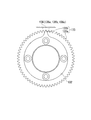
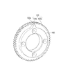
- a gear 133 is formed on the outer peripheral surface of the encoder disk 132 as a detection pattern.
- the encoder disk 132 is formed in a donut board shape with a hole in the center. The inner diameter of the hole is set larger than the outer diameter of the screw shaft 1.
- the adapter 135 is also provided with a through hole having the same inner diameter as that of the encoder disk 132. Therefore, when the screw shaft 1 linearly moves in the direction of the central axis L, the screw shaft 1 can penetrate the encoder disk 132 and the adapter 135 and linearly move.
- the gear 133 has tooth tips (flat teeth) parallel to the central axis L direction.
- the gear 133 is formed by overlapping two first tooth tips 133 a and second tooth tips 133 b in the thickness direction of the encoder disk 132.
- a first tooth tip 133 a having a width of 5 mm is formed in the thickness direction from the surface of the encoder disk 132 that contacts the adapter 135.
- a second second tooth tip 133b having a width of 5 mm is formed overlapping the first tooth tip 133a in the thickness direction.
- the first tooth tip 133 a has, for example, 64 teeth formed on the outer peripheral surface of the encoder disk 132 at equal intervals.
- the second tooth tip 133 b is formed with one tooth on the outer peripheral surface of the encoder disk 132.
- Two detection patterns (a first tooth tip 133 a and a second tooth tip 133 b) are formed on the outer peripheral surface of the encoder disk 132.
- One of the plurality of teeth of the first tooth tip 133a and one tooth of the second tooth tip 133b are integrally formed.
- the tooth profile of the first tooth tip 133a and the second tooth tip 133b is not limited to the involute curve.
- the tooth profile of the first tooth tip 133a and the second tooth tip 133b may be a cycloid curve or a trochoid curve.
- the tooth shapes of the first tooth tip 133a and the second tooth tip 133b may be trapezoidal or flat.
- the tooth shapes of the first tooth tip 133a and the second tooth tip 133b have tooth tips (flat teeth) parallel to the central axis L direction in any tooth shape.
- a detector 136 is disposed on the outer peripheral surface side of the encoder disk 132 so as to face the gear 133.
- an electromagnetic induction type detector can be used as this detector 136.
- the electromagnetic induction type detector 136 is fixed to the inner peripheral surface of the housing 74 with an interval of, for example, about 1 mm from the outer peripheral surface (tooth tip) of the encoder disk 132.
- the electromagnetic induction type detector 136 is a chip type sensor incorporating a detection element (excitation coil and detection coil). A signal from the detection element of the electromagnetic induction detector 136 is output to a readout circuit (not shown). The readout circuit detects the electromagnetic induction generated in the detection element in accordance with the presence of the metal to be detected (first tooth tip 133a, second tooth tip 133b), and outputs it as a detection signal via a comparator or the like.
- the electromagnetic induction type detector 136 has two detection elements 136a and 136b for the first tooth tip 133a and one detection element 136c for the second tooth tip 133b.
- an A-phase signal and a B-phase signal are output.
- a Z-phase signal is output. Since the second tooth tip 133 b has one tooth on the outer peripheral surface of the encoder disk 132, the Z-phase signal is output only once for one rotation of the encoder disk 132.
- the Z-phase signal is used as a signal for the origin.
- the detection elements 136a and 136b for detecting the first tooth tip 133a are arranged substantially at the center in the thickness direction (center axis L direction) of the first tooth tip 133a.
- the detection element 136c for detecting the second tooth tip 133b is disposed substantially at the center in the thickness direction (the central axis L direction) of the second tooth tip 133b.
- the electromagnetic induction type detector 136 is disposed on the outer peripheral surface side (radial direction) of the encoder disk 132 with a predetermined distance. Therefore, even when the encoder disk 132 moves in the direction of the central axis L due to the influence of an external force (reaction force), the distance between the encoder disk 132 and the electromagnetic induction detector 136 does not change. For this reason, it is possible to continue to accurately detect the rotation (rotation position, rotation speed, rotation amount) of the nut 2 to which the encoder disk 132 is attached.
- the encoder disk 132 may move in the direction of the central axis L by, for example, about 1 to 2 mm.
- the distance between the encoder disk 132 and the electromagnetic induction detector 136 does not change. Moreover, even if the encoder disk 132 is translated in the direction of the central axis L by about 1 to 2 mm with respect to the electromagnetic induction detector 136, the first tooth tip 133a and the second tooth tip 133a are within the detection range of the electromagnetic induction detector 136. There is a tooth tip 133b. This is because the gear 133 (first tooth tip 133a, second tooth tip 133b) of the encoder 130 is a tooth tip parallel to the central axis direction, and the gear 13 (first tooth tip 133a, second tooth tip).
- the encoder 130 detects the detection pattern (first tooth tip 133a, second tooth tip 133b) of the encoder 130 regardless of the parallel movement of the encoder disk 132 in the central axis L direction, and rotates the nut 2 ( The rotation position, rotation speed, and rotation amount) can be accurately obtained.
- the detection pattern (first tooth tip 133a, second tooth tip 133b) of the encoder disk 132 even in a poor environment where a lot of dust, oil, etc. are present. Can be detected satisfactorily.
- the encoder disk 132 can be easily manufactured.
- the encoder 130 has a plurality of detection patterns (first tooth tip 133a, second tooth tip 133b) corresponding to a plurality of output phases (A phase, B phase, Z phase), rotation of the nut 2 is performed. It can be obtained with high accuracy.
- the actuator A includes the encoder 130 described above, the positioning of the screw shaft 1 can be controlled with high accuracy.
- encoder disk 232 encoder disk 232
- differences from the above-described encoder disk 132 will be mainly described.
- the encoder disk 232 has substantially the same outer shape as the encoder disk 132.
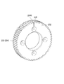
- a gear 233 is formed on the outer peripheral surface of the encoder disk 232 as a detection pattern.
- the gear 233 has a tooth tip 234 having the same shape as the first tooth tip 133a.
- tooth tip 2334 for example, 64 teeth are formed on the outer peripheral surface of the encoder disk 232 at equal intervals.
- the length of the tooth tip 234 in the central axis L direction is formed substantially the same as the thickness of the encoder disk 132.
- the tooth tip 234 is formed with a width of 10 mm in the thickness direction of the encoder disk 132. This is almost twice the length (thickness) of the first tooth tip 133a.
- One of the 64 teeth 234k is formed such that the length (thickness) in the direction of the central axis L is about half of the length of the other teeth.
- the teeth 234k are formed with a width of 5 mm in the thickness direction of the encoder disk 132.
- the length of the first tooth tip 133a is the same as that described above.
- the teeth 234k are formed with the same tooth width at the same time as the other teeth, and then processed into a half tooth width by an end mill or the like.
- a groove 235 extending in the central axis L direction is formed on the outer peripheral surface of the encoder disk 232 at the same position as the teeth 234k in the circumferential direction.
- the length of the groove 235 in the central axis L direction is 5 mm.
- the groove 235 is formed deeper than the tooth base of the tooth 234k (gear 233).
- two detection patterns (tooth tips 234, grooves 235) are formed on the outer peripheral surface of the encoder disk 232.
- the two detection elements 136a and 136b of the electromagnetic induction detector 136 detect a region of the tooth tip 234 where the groove 235 does not exist in the width direction.
- the two detection elements 136a and 136b output an A phase signal and a B phase signal.
- the detection element 136c of the electromagnetic induction detector 136 detects an area where the groove 235 exists in the width direction in the tooth tip 234.
- One detection element 136c outputs a Z-phase signal by not detecting the groove 235. Since the bottom of the groove 235 is outside the detection range of the detection element 136c, the detection element 136c cannot detect the groove 235. For this reason, the detection element 136c outputs the same signal as the detection elements 136a and 136b in the region where the tooth tip 234 exists. On the other hand, the detection element 136c outputs a signal different from the detection elements 136a and 136b in a portion where the groove 235 exists.
- the detection element 136c may be a case where no signal is output in a portion where the groove 235 exists. Therefore, the detection element 136 c outputs a Z-phase signal only once per rotation of the encoder disk 132 corresponding to the groove 235.
- the encoder disk 232 since the encoder disk 232 only forms (processes) the small groove 235 after forming the tooth tip 234, the processing time is short and can be manufactured at low cost.
- the present invention is not limited thereto. Any mechanism / form may be used as long as it is a rotational linear conversion mechanism that converts rotational motion into linear motion.
- the present invention is not limited to this.
- a deflector type or an end cap type may be used.
- the nut 2 was rotated as a drive part of the actuator A was demonstrated, it is not restricted to this. It may be a case where the screw shaft 1 is rotated and the nut 2 is linearly moved.
- the encoder 130 is not limited to detecting the amount of movement of the drive unit, but may be a case of detecting the amount of movement of the output unit. In this case, a detent mechanism that restricts the rotation of the nut 2 around the central axis L is provided in place of the detent mechanism (1a, 75a).
- the electromagnetic induction type has been described as the encoder 130 (detector 136), but is not limited thereto. For example, it may be optical, magnetic, or contact type.
- the present invention is not limited to this.
- it may be a slit hole, a magnetic pattern, or the like.
- the rotation of the rotational motion can be detected stably.
- the linear motion unit can be controlled with high accuracy.
Landscapes
- Physics & Mathematics (AREA)
- General Physics & Mathematics (AREA)
- Transmission Devices (AREA)
- Transmission And Conversion Of Sensor Element Output (AREA)
Abstract
L'invention concerne un codeur (130) destiné à une utilisation avec un actionneur (A) qui fait tourner une unité de déplacement en rotation (2) raccordée, soit directement soit indirectement, à une unité de déplacement linéaire (1) et déplace linéairement l'unité de déplacement linéaire (1) dans la direction d'un axe central (L). Le codeur (130) est équipé des éléments suivants : un disque de codeur (132), qui est monté à une extrémité dans la direction de l'axe central (L) de l'unité de déplacement en rotation (2), et dont la surface périphérique extérieure porte un motif de détection ; et un détecteur (136), qui est disposé de façon à faire face à la surface périphérique extérieure, et qui détecte le motif de détection.
Priority Applications (1)
| Application Number | Priority Date | Filing Date | Title |
|---|---|---|---|
| JP2012526420A JPWO2012014697A1 (ja) | 2010-07-30 | 2011-07-14 | エンコーダ、アクチュエータ |
Applications Claiming Priority (2)
| Application Number | Priority Date | Filing Date | Title |
|---|---|---|---|
| JP2010-172261 | 2010-07-30 | ||
| JP2010172261 | 2010-07-30 |
Publications (1)
| Publication Number | Publication Date |
|---|---|
| WO2012014697A1 true WO2012014697A1 (fr) | 2012-02-02 |
Family
ID=45529913
Family Applications (1)
| Application Number | Title | Priority Date | Filing Date |
|---|---|---|---|
| PCT/JP2011/066134 Ceased WO2012014697A1 (fr) | 2010-07-30 | 2011-07-14 | Codeur et actionneur |
Country Status (2)
| Country | Link |
|---|---|
| JP (1) | JPWO2012014697A1 (fr) |
| WO (1) | WO2012014697A1 (fr) |
Cited By (2)
| Publication number | Priority date | Publication date | Assignee | Title |
|---|---|---|---|---|
| CN111247396A (zh) * | 2017-11-07 | 2020-06-05 | Cts公司 | 包括开关和图案化磁体的旋转位置传感器 |
| CN113383209A (zh) * | 2018-12-06 | 2021-09-10 | 谐波传动系统有限公司 | 双绝对式编码器 |
Citations (3)
| Publication number | Priority date | Publication date | Assignee | Title |
|---|---|---|---|---|
| JPS6450910A (en) * | 1987-08-21 | 1989-02-27 | Tamagawa Seiki Co Ltd | Magnetic encoder |
| JP2000257604A (ja) * | 1999-03-05 | 2000-09-19 | Hirata Corp | 直動駆動装置及びこれを用いた直動駆動方法 |
| JP2007120621A (ja) * | 2005-10-28 | 2007-05-17 | Ogino Kogyo Kk | 位置決め装置 |
-
2011
- 2011-07-14 WO PCT/JP2011/066134 patent/WO2012014697A1/fr not_active Ceased
- 2011-07-14 JP JP2012526420A patent/JPWO2012014697A1/ja not_active Withdrawn
Patent Citations (3)
| Publication number | Priority date | Publication date | Assignee | Title |
|---|---|---|---|---|
| JPS6450910A (en) * | 1987-08-21 | 1989-02-27 | Tamagawa Seiki Co Ltd | Magnetic encoder |
| JP2000257604A (ja) * | 1999-03-05 | 2000-09-19 | Hirata Corp | 直動駆動装置及びこれを用いた直動駆動方法 |
| JP2007120621A (ja) * | 2005-10-28 | 2007-05-17 | Ogino Kogyo Kk | 位置決め装置 |
Cited By (4)
| Publication number | Priority date | Publication date | Assignee | Title |
|---|---|---|---|---|
| CN111247396A (zh) * | 2017-11-07 | 2020-06-05 | Cts公司 | 包括开关和图案化磁体的旋转位置传感器 |
| CN111247396B (zh) * | 2017-11-07 | 2022-11-04 | Cts公司 | 包括开关和图案化磁体的旋转位置传感器 |
| CN113383209A (zh) * | 2018-12-06 | 2021-09-10 | 谐波传动系统有限公司 | 双绝对式编码器 |
| CN113383209B (zh) * | 2018-12-06 | 2024-03-29 | 谐波传动系统有限公司 | 双绝对式编码器 |
Also Published As
| Publication number | Publication date |
|---|---|
| JPWO2012014697A1 (ja) | 2013-09-12 |
Similar Documents
| Publication | Publication Date | Title |
|---|---|---|
| CN103097771A (zh) | 电动致动器 | |
| JP4875111B2 (ja) | 角度位置を検出する検出装置、電動機、ステアリングコラムおよび減速装置 | |
| US20110016960A1 (en) | Device For Detecting Angular Position, Electric Motor, Steering Column And Reduction Gear | |
| JP5955309B2 (ja) | 電動リニアアクチュエータ及びその電動モータ | |
| JP6275406B2 (ja) | 磁気エンコーダ装置および回転検出装置 | |
| JP5878381B2 (ja) | 多回転アブソリュートロータリーエンコーダ | |
| KR20040058208A (ko) | 다회전식 인코더 | |
| US20200304003A1 (en) | Adaptive installation rotary encoder | |
| JPWO2012014697A1 (ja) | エンコーダ、アクチュエータ | |
| TW202448082A (zh) | 致動器 | |
| WO2022202654A1 (fr) | Dispositif d'engrenage à modulation magnétique, dispositif d'entraînement et robot | |
| JP2015117787A (ja) | 電動アクチュエータ | |
| US20210257886A1 (en) | Electric actuator | |
| US10739163B2 (en) | Sensor assembly for determining a number of rotations of a permanent magnet | |
| JP2017082918A (ja) | 回転制限装置、これを備える回転直動変換装置、電動パワーステアリング装置および車両並びに機械装置 | |
| JP7853083B2 (ja) | 回転テーブル装置 | |
| JP2005031011A (ja) | 位置検出装置 | |
| KR20200052858A (ko) | 모터 | |
| JP6565476B2 (ja) | 回転直動変換装置、これを備える電動パワーステアリング装置および車両並びに機械装置 | |
| JP2013093964A (ja) | 直線運動案内機構付アクチュエータ | |
| JP5495058B2 (ja) | 車両用操舵装置及びその製造方法 | |
| US20260109393A1 (en) | Vehicle steering apparatus and vehicle including the same | |
| WO2020085162A1 (fr) | Structure de transmission de puissance magnétique | |
| KR20250069268A (ko) | 중공축 모터에 구비되어 회전량을 검출하는 엔코더 | |
| JP2024108378A (ja) | 直動アクチュエータ、直動アクチュエータシステム、および、リードの算出方法 |
Legal Events
| Date | Code | Title | Description |
|---|---|---|---|
| 121 | Ep: the epo has been informed by wipo that ep was designated in this application |
Ref document number: 11812289 Country of ref document: EP Kind code of ref document: A1 |
|
| WWE | Wipo information: entry into national phase |
Ref document number: 2012526420 Country of ref document: JP |
|
| NENP | Non-entry into the national phase |
Ref country code: DE |
|
| 122 | Ep: pct application non-entry in european phase |
Ref document number: 11812289 Country of ref document: EP Kind code of ref document: A1 |