WO2012014985A1 - ジェットミル - Google Patents
ジェットミル Download PDFInfo
- Publication number
- WO2012014985A1 WO2012014985A1 PCT/JP2011/067289 JP2011067289W WO2012014985A1 WO 2012014985 A1 WO2012014985 A1 WO 2012014985A1 JP 2011067289 W JP2011067289 W JP 2011067289W WO 2012014985 A1 WO2012014985 A1 WO 2012014985A1
- Authority
- WO
- WIPO (PCT)
- Prior art keywords
- chamber
- classification
- jet mill
- powder
- pulverization
- Prior art date
- Legal status (The legal status is an assumption and is not a legal conclusion. Google has not performed a legal analysis and makes no representation as to the accuracy of the status listed.)
- Ceased
Links
Images

Classifications
-
- B—PERFORMING OPERATIONS; TRANSPORTING
- B02—CRUSHING, PULVERISING, OR DISINTEGRATING; PREPARATORY TREATMENT OF GRAIN FOR MILLING
- B02C—CRUSHING, PULVERISING, OR DISINTEGRATING IN GENERAL; MILLING GRAIN
- B02C19/00—Other disintegrating devices or methods
- B02C19/06—Jet mills
- B02C19/066—Jet mills of the jet-anvil type
-
- B—PERFORMING OPERATIONS; TRANSPORTING
- B02—CRUSHING, PULVERISING, OR DISINTEGRATING; PREPARATORY TREATMENT OF GRAIN FOR MILLING
- B02C—CRUSHING, PULVERISING, OR DISINTEGRATING IN GENERAL; MILLING GRAIN
- B02C19/00—Other disintegrating devices or methods
- B02C19/06—Jet mills
-
- B—PERFORMING OPERATIONS; TRANSPORTING
- B02—CRUSHING, PULVERISING, OR DISINTEGRATING; PREPARATORY TREATMENT OF GRAIN FOR MILLING
- B02C—CRUSHING, PULVERISING, OR DISINTEGRATING IN GENERAL; MILLING GRAIN
- B02C19/00—Other disintegrating devices or methods
- B02C19/06—Jet mills
- B02C19/068—Jet mills of the fluidised-bed type
-
- B—PERFORMING OPERATIONS; TRANSPORTING
- B02—CRUSHING, PULVERISING, OR DISINTEGRATING; PREPARATORY TREATMENT OF GRAIN FOR MILLING
- B02C—CRUSHING, PULVERISING, OR DISINTEGRATING IN GENERAL; MILLING GRAIN
- B02C23/00—Auxiliary methods or auxiliary devices or accessories specially adapted for crushing or disintegrating not provided for in preceding groups or not specially adapted to apparatus covered by a single preceding group
- B02C23/08—Separating or sorting of material, associated with crushing or disintegrating
- B02C23/10—Separating or sorting of material, associated with crushing or disintegrating with separator arranged in discharge path of crushing or disintegrating zone
- B02C23/12—Separating or sorting of material, associated with crushing or disintegrating with separator arranged in discharge path of crushing or disintegrating zone with return of oversize material to crushing or disintegrating zone
-
- B—PERFORMING OPERATIONS; TRANSPORTING
- B07—SEPARATING SOLIDS FROM SOLIDS; SORTING
- B07B—SEPARATING SOLIDS FROM SOLIDS BY SIEVING, SCREENING, SIFTING OR BY USING GAS CURRENTS; SEPARATING BY OTHER DRY METHODS APPLICABLE TO BULK MATERIAL, e.g. LOOSE ARTICLES FIT TO BE HANDLED LIKE BULK MATERIAL
- B07B7/00—Selective separation of solid materials carried by, or dispersed in, gas currents
- B07B7/08—Selective separation of solid materials carried by, or dispersed in, gas currents using centrifugal force
- B07B7/083—Selective separation of solid materials carried by, or dispersed in, gas currents using centrifugal force generated by rotating vanes, discs, drums, or brushes
-
- B—PERFORMING OPERATIONS; TRANSPORTING
- B07—SEPARATING SOLIDS FROM SOLIDS; SORTING
- B07B—SEPARATING SOLIDS FROM SOLIDS BY SIEVING, SCREENING, SIFTING OR BY USING GAS CURRENTS; SEPARATING BY OTHER DRY METHODS APPLICABLE TO BULK MATERIAL, e.g. LOOSE ARTICLES FIT TO BE HANDLED LIKE BULK MATERIAL
- B07B7/00—Selective separation of solid materials carried by, or dispersed in, gas currents
- B07B7/08—Selective separation of solid materials carried by, or dispersed in, gas currents using centrifugal force
- B07B7/086—Selective separation of solid materials carried by, or dispersed in, gas currents using centrifugal force generated by the winding course of the gas stream
Definitions
- the present invention relates to a jet mill that finely pulverizes toner, powder paint, minerals, and the like.
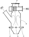
- This type of jet mill has a cylindrical container 20 capable of storing raw material powder (hereinafter simply referred to as “powder”) as shown in FIG.
- a fluidized bed type jet mill in which a plurality of gas ejection nozzles 21 are provided so as to face each other from the wall toward the center, and the powders collide with each other by being placed on the gas ejected from the gas ejection nozzle 21. is there.
- the jet mill having this configuration stable performance can be obtained.
- the powder is retained in the machine and pulverized, there is a problem that the powder remains in the machine after the pulverization is completed.
- the powder is swirled together with the air current and pulverized by a gas jet nozzle provided on the peripheral wall of a cylindrical pulverization chamber as exemplified in Patent Document 1 and Patent Document 2 below.
- a jet mill that classifies a pulverized powder by sending it to a classification chamber above the pulverization chamber.
- a plurality of gas ejection nozzles are attached to the outer peripheral wall of the crushing chamber so as to be inclined with each other, and powder is placed on the ejection gas by the ejection gas from the gas ejection nozzle and swirled at high speed. Crush in.
- a collision member is provided at a position facing the gas ejection port of the gas ejection nozzle with a predetermined interval, and pulverized by causing the powder to collide with the collision member on the ejection gas.
- These jet mills of Patent Documents 1 and 2 are provided with a classification chamber in which a classification rotor is arranged in the upper part of the pulverization chamber, and classifies and collects the powder that has been pulverized to a desired particle size.
- the grinding chamber and the classification chamber are partitioned by a ring-shaped member and are in a partitioned state.
- the powder pulverized in the pulverization chamber should be sent to the classification chamber. Will stay.
- the classification chamber the powder pulverized to a predetermined particle size or less is discharged outside the machine and collected, but some of the powder not pulverized to the predetermined particle size is returned to the pulverization chamber, It stays in the classification chamber as it is.
- the pressure loss in the classification chamber increases, and the powder concentration in the classification chamber also increases, which may prevent normal classification.
- the present invention is to provide a jet mill that is compact but has high pulverization efficiency and low stagnation of powder during operation.
- a first characteristic configuration of the present invention is a jet mill having a cylindrical pulverization chamber and a classification chamber communicating with the pulverization chamber, wherein the classification chamber is provided with a classification rotor communicating with the fine powder discharge port, and the pulverization chamber Is provided with a raw material supply port and at least one gas ejection nozzle arranged to be inclined from the outer peripheral wall surface toward the rotation direction of the classification rotor, and the classification chamber is started from the inner peripheral wall surface of the pulverization chamber. It is in the shape of a cone inclined toward the classifying rotor along the axis.
- the pulverization chamber is cylindrical, and the classification chamber connected to the pulverization chamber is conical, so that the powder pulverized in the pulverization chamber is separated from the pulverization chamber by the flow of gas ejected from the gas ejection nozzle. While turning along the inner peripheral surface, it also turns along the inner peripheral surface of the classification chamber. At this time, the powder having a large particle diameter swirls in the outer crushing chamber and the area close to the crushing chamber because the swirling speed is large. This area is a pulverization area, and the powder continues to be pulverized. On the other hand, since the powder having a small particle size has a low swirl speed, it reaches the classification region in the classification chamber along the inner peripheral surface of the inner classification chamber.
- the fine powder moves to the classification area away from the grinding chamber and is subjected to the classification action by the classification rotor.
- unnecessary movement of the powder from the crushing chamber to the classification chamber is suppressed, the coarse powder to be crushed is kept in the crushing chamber, and the pulverized powder is promptly sent to the classification chamber.
- the fine powder is guided to the classification rotor, passes through the classification rotor, and is discharged out of the machine.
- the powder having an intermediate particle diameter enters the classification chamber, it is bounced by the classification rotor and returned to the grinding chamber.
- the gas can be efficiently pulverized by the collision with the inner peripheral wall surface of the pulverization chamber or between the powders in the pulverization region by the gas ejected from the gas ejection nozzle.
- the powder in the middle of pulverization in the classification chamber (corresponding to coarse powder having a relatively large particle diameter) can be reduced, the load on the classification rotor is reduced, and the coarse powder in the product is reduced. Mixing can also be suppressed.
- Another characteristic configuration of the present invention includes a truncated cone-shaped adapter that is inclined inward along the axis from the bottom surface of the grinding chamber toward the base end side of the classification rotor at the center of the grinding chamber. It is.
- the coarse powder from the classification chamber can be effectively guided to the inner wall surface of the crushing chamber. Further, by providing the truncated cone adapter at the center of the grinding chamber, unnecessary space in the grinding chamber can be reduced. That is, when there is no frustoconical adapter, the space volume of the crushing chamber becomes large, and a region where the speed of the swirling flow is small is formed at the center of the crushing chamber. In this region, coarse powder that has not been classified in the classification chamber or powder having an intermediate particle size is retained.
- the provision of the conical base eliminates the space at the center of the crushing chamber, so that the powder can be directed toward the inner peripheral surface of the crushing chamber having a high swirl speed. As a result, the powder does not stay in the central portion, and the powder in the middle of pulverization can be effectively led to the pulverization region, and as a result, the pulverization efficiency can be improved.
- grinding efficiency means the processing capacity of the jet mill per unit air volume.
- the unit air volume refers to the volume of gas per unit time ejected from the gas ejection nozzle.
- it means the total value of the volume of gas per unit time ejected from each gas ejection nozzle.
- a jet mill having a high crushing efficiency refers to a jet mill having a large processing capacity even with the same air volume, and the present invention capable of obtaining a high crushing efficiency is advantageous from the viewpoint of energy saving.
- Another characteristic configuration of the present invention is that a collision member is provided to face the tip of the gas ejection nozzle at a predetermined interval.
- the powder can be reliably collided with the collision member, so that a strong impact force can be applied to the powder. That is, the impact force that the powder receives from the collision member is greater than when the powder collides. In particular, the smaller the particle size of the powder, the smaller the chance of collision and the impact force between the powders. Therefore, sufficient impact force could not be given to the powder.
- the collision member by providing the collision member, it is possible to reliably apply an impact force to the powder, and it is possible to effectively pulverize. As a result, the pulverization efficiency is improved and the retention amount in the machine is reduced. Further, by disposing the collision member in the pulverization region where the powder is swirling, collision pulverization with the powder being swirled is also performed, so that the pulverization efficiency is improved and the retention amount in the machine is reduced.
- Another feature of the present invention is that the collision surface of the collision member is inclined toward the inner wall surface side of the casing of the crushing chamber with respect to the gas ejection nozzle.
- the collision surface of the collision member is inclined toward the inner wall surface side of the casing of the crushing chamber with respect to the gas ejection nozzle, most of the powder colliding with the collision surface is along the collision angle with the inclined surface. It is bounced back to the inner wall surface of the casing of the grinding chamber and collides with the inner wall surface of the casing. The crushing further proceeds by this collision.
- the collision member is configured by one of a cone, a pyramid, and an obliquely cut cylinder or prism.
- the collision member is either a cone, a pyramid, or an obliquely cut cylinder or prism, so that the powder rebounds and travels after colliding with the collision member according to the type of powder and the target particle size. Can be controlled.
- Another feature of the present invention is that the crushing chamber and the classification chamber are integrally arranged sideways.
- the powder By arranging the pulverization chamber and the classification chamber horizontally as one body, the powder can be collected in the pulverization region located below the pulverization chamber by using gravity in the pulverization chamber. The chance of collision between the powder and the collision member can be surely increased. Thereby, the grinding efficiency can be further improved.
- Another characteristic configuration of the present invention is that the gas ejection nozzle is disposed substantially horizontally in the lower position of the grinding chamber.
- Accelerating force can be applied to the powder more reliably and effectively pulverized by providing the gas jet nozzle in a substantially horizontal direction in the pulverization region below the pulverization chamber in which the powder is collected.
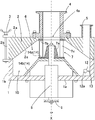
- FIG. 1 is a sectional view showing an embodiment of a jet mill according to the present invention.
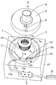
- FIG. 2 is a perspective view showing an embodiment of the jet mill of the present invention.
- FIG. 3 is a perspective view showing another embodiment of the jet mill of the present invention.
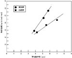
- FIG. 4 is a graph showing the performance of an example and a comparative example using the jet mill of the present invention.
- FIG. 5 is a schematic view of a jet mill used as a comparative example in the examples of the present invention.
- the jet mill according to the first embodiment of the present invention includes a bottomed cylindrical lower casing 1 that opens upward, and an upper casing 2 that is superimposed on the lower casing 1.
- the upper casing 2 is detachably attached to the lower casing 1 by a fastener 3.
- FIG. 1 when the upper casing 2 is attached to the lower casing 1, the upper casing 2 and the lower casing 1 have a common vertical axis X.
- FIG. 2 shows a state where the upper casing 2 is removed.
- the lower casing 1 generally includes a generally disc-shaped bottom portion 1a having a through hole in the center, and a cylindrical side wall portion 1b extending generally upward in the vertical direction from the radially outer end of the bottom portion 1a. It has a cup shape.
- the upper casing 2 has a generally annular shape with a fine powder discharge port 4a for discharging fine powder at the center. More specifically, the upper casing 2 includes an upper surface 2a that extends generally horizontally, a cylindrical outer peripheral surface 2b that extends generally downward in the vertical direction from the radially outer end of the upper surface 2a, and an outer peripheral surface 2b. It has a generally conical inner peripheral surface 2c extending substantially linearly obliquely upward from the lower end to the radially inner end of the upper surface 2a, that is, the fine powder discharge port 4a.
- the fine powder discharge pipe 4 is connected to the upper part of the fine powder discharge port 4a so as to share the axis X. Further, a raw material supply pipe 5 (an example of a raw material supply port) penetrating the upper casing 2 in the vertical direction is provided at one location near the outer periphery of the upper casing 2, and powder as an object to be processed is supplied with this raw material. It is supplied to the lower casing 1 via the pipe 5.
- a raw material supply pipe 5 an example of a raw material supply port penetrating the upper casing 2 in the vertical direction is provided at one location near the outer periphery of the upper casing 2, and powder as an object to be processed is supplied with this raw material. It is supplied to the lower casing 1 via the pipe 5.
- a flat circular upper surface 14a having an outer shape slightly larger than the fine powder discharge port 4a, and an inclined side surface 14b that gradually spreads outward from the outer periphery of the upper surface 14a toward the bottom 1a.
- a truncated cone-shaped bottom plate 14 (an example of a truncated cone-shaped adapter) is attached.
- the outer diameter of the lower end portion of the bottom plate 14 that is, the maximum outer diameter is set sufficiently smaller than the inner diameter of the side wall portion 1 b of the lower casing 1, the outer periphery of the bottom plate 14 and the inner surface of the side wall portion 1 b of the lower casing 1.
- a part (outermost peripheral part) of the bottom part 1a of the lower casing 1 is extended as a generally flat annular part.
- a generally frustoconical space is formed inside the jet mill by the conical inner peripheral surface 2c of the upper casing 2 and the inclined side surface 14b of the bottom plate 14, and this frustoconical space is particularly crushed.
- the lower crushing chamber 10 is divided into an upper classification chamber 6 in which classification is performed.
- the pulverization chamber 10 is provided with a gas ejection nozzle 11.
- the gas ejection nozzle 11 is provided at the tip of a gas ejection pipe 11p installed so as to penetrate the side wall portion 1b of the lower casing 1, and from the outer peripheral wall surface of the side wall portion 1b to the rotational direction side of the classification rotor 7 described later. It is arranged at an angle.
- the proximal end side of the gas ejection pipe 11p is connected to the compressor 30 by a gas supply hose 11b.
- a gas storage tank T fixed to the casing 20 that supports the jet mill is interposed between the gas supply hoses 11b.
- the gas ejection pipe 11p and the gas ejection nozzle 11 are disposed so as to be inclined laterally with respect to the radial direction of the lower casing 1, the highly compressed gas from the compressor 30 is discharged from the gas ejection nozzle 11.
- a high-speed swirling flow of gas is generated in the grinding chamber 10.
- the inclination angle with respect to the radial direction of the gas ejection pipe 11p and the gas ejection nozzle 11 is preferably set within a range of about 40 degrees to about 70 degrees. Any angle that is necessary for generating a swirling flow in the crushing chamber 10 may be used.
- the crushing chamber 10 is provided with a collision member 12 as a crushing means.
- the collision member 12 is disposed at a position spaced inward from the side wall 1b and the bottom 1a of the lower casing 1 by a predetermined distance, and is provided on the side opposite to the columnar base 12b and the rod-like member 12c of the base 12b. And a conical impact surface 12a.
- the collision member 12 is disposed at one end of a rod-shaped member 12 c installed in parallel with the gas ejection pipe 11 p, and the rod-shaped member 12 c generally extends in the radial direction of the side wall portion 1 b of the lower casing 1. It is supported by the front-end
- the support member 13 supports the rod-like member 12c so that not only the collision member 12 but also the other end of the rod-like member 12c is separated from the inner surfaces of the bottom portion 1a and the side wall portion 1b of the lower casing 1.
- the collision surface 12a is disposed so as to face the swirling flow created by the gas ejection nozzle 11 and the ejection port 11a itself of the gas ejection nozzle 11.
- the collision surface 12a and the ejection port 11a of the gas ejection nozzle 11 are set to face each other with a predetermined interval.
- the predetermined interval in the present invention is set as a distance at which the powder accelerated by the gas ejection nozzle 11 is maintained at a speed sufficient to be crushed and crushed.
- the predetermined interval varies depending on the inner diameter of the lower casing 1, the diameter of the ejection port 11 a, and the amount of air blown, but is preferably set to about 30 mm to about 260 mm.
- the predetermined interval is set to about 70 mm to about 130 mm. Is preferred.
- the powder can be finely pulverized by causing the powder supplied from the raw material supply pipe 5 into the pulverization chamber 10 to collide with the collision surface 12a by the gas ejected from the gas ejection nozzle 11 (jet airflow). .
- At least a part of the conical collision surface 12a that is, a portion close to the side wall 1b of the lower casing 1 is a specific surface inclined toward the side wall 1b of the lower casing 1 with respect to the radial direction about the axis X. Therefore, most of the powder reflected on this specific surface continues to collide with the side wall 1b of the lower casing 1 and further pulverization proceeds.
- a classification rotor 7 that is driven to rotate about the axis X is provided between the radial center of the classification chamber 6, more specifically, between the flat upper surface of the bottom plate 14 and the fine powder outlet 4 a of the upper casing 2. It has been.
- the classification rotor 7 has a generally cylindrical shape, and the outer peripheral surface thereof is connected to the frustoconical classification chamber 6, and the upper end of the classification rotor 7 is connected to the fine powder discharge port 4 a.
- the classification rotor 7 is vertically moved from a space below the lower casing 1 to a space above the upper surface 14a of the bottom plate 14 through through holes formed in the center portions of the bottom plate 14 and the lower casing 1. It is attached to the upper end of the extended rotating shaft 8. A pulley 9 is attached to the lower end of the rotating shaft 8, and the classifying rotor 7 is rotated in the direction of the arrow shown in FIG. Note that the rotation direction of the classification rotor 7 coincides with the direction of the jet airflow by the gas ejection nozzle 11.
- the classification rotor 7 includes a lower ring member 7a connected to the upper end of the rotary shaft 8, an upper ring member 7b disposed to face the lower surface around the through hole of the upper casing 2 forming the fine powder discharge port 4a, and a lower ring member 7a and the upper ring member 7b, and a large number of classifying blades 7c extended vertically.
- Each classification blade 7c is a rectangular plate extending vertically and vertically, and the inner diameter of the upper ring member 7b substantially coincides with the inner diameter of the fine powder discharge pipe 4.
- the lower ring member 7c includes a frustoconical base end connected to the upper end of the rotary shaft 8, and a disc-like portion extending radially outward from the lower end of the base end.
- the classification blade 7c is erected upward from the upper surface of the shape portion.
- the outer diameter of the disk-shaped part is substantially the same as the upper surface 14 a of the bottom plate 14, and the disk-shaped part is disposed opposite to the upper surface 14 a of the bottom plate 14.
- the classification rotor 7 is supported in a cantilever manner with respect to the rotating shaft 8 via a lower ring member 7 a.
- the shape and number of the classification blades 7c are not limited to those illustrated in FIGS. 1 and 2, and can be arbitrarily selected.
- the shape of the classification blade 7c is a flat plate shape, a wedge shape with a thick outer peripheral side and a thin inner side, a water drop shape with a curved outer peripheral side, a curved flat plate shape, a bent top end portion of the flat plate, an upper part of the classification rotor 7 It can be selected from those having an outer diameter larger than that of the lower part.
- the classifying blades 7c are arranged radially from the center along the outer peripheral surface of the classifying rotor 7. However, the classifying blades 7c may be arranged to be inclined in the counter-rotating direction side with respect to the center. In addition, with the upper casing 2 attached, a slight gap is formed between the lower surface around the through hole of the upper casing 2 and the upper end surface of the upper ring member 7b of the classification rotor 7 so as not to contact. Has been.
- annular grooves are provided on the inner surface of the upper casing 2 facing the upper ring member 7b of the classifying rotor 7 so as to be separated from each other in the radial direction.
- the gap between the upper casing 2 and the classification rotor 7 is labyrinth-sealed, and the phenomenon that coarse powder escapes from the classification chamber 6 to the fine powder discharge pipe 4 is prevented.
- a slight gap is formed so as not to contact between the lower ring member 7 a and the upper surface 14 a of the bottom plate 14.
- the powder supplied from the raw material supply pipe 5 is accelerated by the gas ejected from the gas ejection nozzle 11 and is pulverized by the collision with the collision member 12 and the inner peripheral wall surface of the lower casing 1 or the collision between the powders. .
- the powder is configured such that the powder collides with the collision member 12 and the powder collide repeatedly while the cone-shaped inner peripheral surface of the upper casing 2 is swung at high speed, and the pulverization of the powder proceeds.
- the fine powder pulverized in the pulverization process is transferred from the pulverization chamber 10 to the classification chamber 6 while rotating at high speed along the inner wall surface.
- the finely pulverized fine powder is classified by the classification rotor 7, passes through the classification rotor 7, is discharged out of the apparatus from the fine powder discharge pipe 4, and is a known collection means such as a cyclone or a dust collector. Is recovered by.
- coarse powder larger than a predetermined particle size is not passed through the classification rotor 7, but is carried to the lower side of the classification rotor 7, returned to the crushing chamber 10, and pulverized again.
- the size and inclination angle of the bottom end of the bottom plate 14 can be arbitrarily set.
- the inner diameter of the lower casing 1 is about 400 mm and the height of the inner wall surface is about 75 mm
- the outer diameter of the upper end of the bottom plate 14 is about 170 mm
- the outer diameter of the lower end is about 300 mm
- the inclination angle is about 50 degrees.
- the height can be about 75 mm.
- the outer diameter of the lower end of the bottom plate 14 may be larger than the outer diameter of the upper end so as to form an inclined surface.
- the lower casing 1 It is preferable to set it to 1/2 or more of the inner diameter.
- the fine powder discharge port 4 a may be provided on the upper surface of the bottom plate 14, and the fine powder discharge pipe 4 may be passed through the bottom plate 14 and pulled out below the lower casing 1.
- the classification rotor 7, the rotating shaft 8, and the pulley 9 are supported on the upper side of the upper casing 2.
- the number of gas ejection nozzles 11 attached to the lower casing 1 is not limited to one and may be a plurality.
- the aperture diameter of the jet nozzle 11a can also be appropriately changed according to the type, properties, particle size, or target particle size of the powder.
- the collision member 12 is not necessarily provided, but the powder is finely pulverized by collision between powders or collision of the powder with the inner peripheral wall surface of the lower casing 1 by rotating in the crushing chamber 10 at high speed. Is done.
- the shape of the collision surface 12a of the collision member 12 is not limited to the conical shape, and may be a pyramid or a spherical surface.
- the base portion 12b may be a prism or a sphere in addition to a cylinder.
- the collision surface 12a has a diameter with respect to the axis X so that the rebound after the powder collides with the collision surface 12a faces the inner wall surface of the lower casing 1. It is preferable to comprise a surface inclined toward the side wall 1b of the lower casing 1 with respect to the direction.
- the material of the collision surface 12a of the collision member 12 is preferably made of cemented carbide or ceramics from the viewpoint of preventing damage due to wear, but is not necessarily limited to these depending on the type of powder.
- Aluminum oxide, zirconium oxide, tungsten carbide, silicon carbide, titanium carbide, silicon nitride, titanium nitride and the like can be used as suitable cemented carbides and ceramics, but are not limited thereto.
- the collision member 12 When pulverizing a heat-sensitive raw material, the collision member 12 can be cooled.
- a cooling method a method in which a refrigerant flow path is provided in the collision member and the refrigerant flows can be considered.
- the pulverization force can be adjusted by appropriately changing the interval between the gas ejection nozzle 11 and the collision member 12. That is, these configurations can be appropriately changed according to the type, properties, particle size, or target particle size of the powder.
- the connecting means for connecting the support member 13 and the rod-like member 12c is configured to be able to adjust the distance between the collision surface 12a and the jet port 11a.
- the materials of the lower casing 1, the upper casing 2, the fine powder discharge pipe 4, the classification rotor 7, the gas ejection nozzle 11, and the bottom plate 14 are not particularly limited, and may be made of a general material such as stainless steel. However, in the case of a powder having a strong action to be worn, it is preferable that at least a part in contact with the powder is made of cemented carbide or ceramics in addition to the gas ejection nozzle 11 and the collision member 12.
- Aluminum oxide, zirconium oxide, tungsten carbide, silicon carbide, titanium carbide, silicon nitride, titanium nitride and the like can be used as suitable cemented carbides and ceramics, but are not limited thereto.
- FIG. 1 A second embodiment of the present invention will be described with reference to FIG.
- the nozzle 11, the classifying rotor 7 and the like are also attached according to this.
- “Arranged sideways” means that the rotation axis direction of the classifying rotor 7 and the gravity axis direction are substantially orthogonal to each other.
- the basic structure is the same as that of the first embodiment shown in FIGS. 1 and 2, but when it is turned sideways, the raw material supply pipe 5 is placed on the outer peripheral wall surface of the lower casing 1 constituting the grinding chamber 10. It is preferable that the raw material supply pipe 5 is shifted from the center of the lower casing 1 to the side, and is arranged so as to communicate with the grinding chamber 10 along the rotation direction of the classification rotor 7.
- the gas ejection nozzle 11 and the collision member 12 are provided in a substantially horizontal direction at the lower part of the lower casing 1 in the vertical direction. Therefore, since the pulverization action by the gas ejection nozzle 11 and the collision member 12 can be given to the powder in a state where the powder concentration is high in a limited space, the powder is effectively pulverized. Can be made.
- a pulverization test was performed using a horizontal jet mill according to the second embodiment shown in FIG.
- a pulverization test was performed using a fluidized bed type jet mill (Counter Jet Mill 200AFG (manufactured by Hosokawa Micron Corporation)) shown in FIG.
- FIG. 4 shows the results of these grinding tests.
- heavy calcium carbonate having an average particle diameter of 235 ⁇ m was used as an object to be processed.
- the operation was performed by adjusting the rotational speeds of the classifying rotors 7 and 27 so that the average particle diameter of the products obtained by pulverization would be approximately the same, and the pulverization efficiency at that time was compared. Further, after the operation was completed, the mass of the powder remaining in the machine was measured and compared.
- FIG. 4 shows the average particle diameter [ ⁇ m] of the powder obtained by pulverization on the horizontal axis and the processing capacity per unit air volume, that is, the pulverization efficiency [(kg / h) / (m 3 / min)] on the vertical axis. It is a graph. As shown in FIG. 4, although there is no great difference in the average particle diameter of the obtained powder between the example and the comparative example, the example has a better grinding efficiency than the comparative example. I understand. In other words, in the case of obtaining a product having the same average particle diameter, it can be seen that the example can obtain an energy saving effect as compared with the comparative example. Further, the amount of powder remaining in the machine after the end of the operation was 17 kg in the comparative example, which was much less than 2 kg in the example, and the waste of raw materials could be reduced.
- the present invention includes lithium compounds such as lithium carbonate, lithium hydroxide, lithium nickelate, lithium cobaltate, and lithium manganate; sodium nitrate (sodium nitrate), sodium hydroxide, sodium carbonate, sodium bicarbonate, sodium sulfite, sodium nitrite, Sodium compounds such as sodium sulfide, sodium silicate, sodium nitrate, sodium bisulfate, sodium thiosulfate, sodium chloride; magnesium sulfate, magnesium chloride, magnesium hydroxide, magnesium oxide, magnesium carbonate, magnesium acetate, magnesium nitrate, magnesium oxide, water
- Magnesium compounds such as magnesium oxide; aluminum such as aluminum hydroxide, aluminum sulfate, aluminum hydroxide, polyaluminum chloride, aluminum oxide, alum, aluminum chloride, aluminum nitride
- Silicon compounds such as silicon oxide, silicon nitride, silicon carbide, calcium silicate, magnesium silicate, sodium silicate, aluminum silicate, etc .
- Potassium compounds calcium compounds such as calcium carbonate, calcium chloride, calcium sulfate, calcium nitrate, calcium hydroxide; titanium compounds such as titanium oxide, barium titanate, strontium titanate, titanium carbide, titanium nitride; manganese sulfate, carbonic acid Manganese compounds such as manganese and manganese oxide; iron compounds such as iron oxide; cobalt compounds such as cobalt chloride, cobalt carbonate and cobalt oxide; nickel compounds such as nickel hydroxide and nickel oxide; yttrium oxide and yttrium iron garnet Yttrium compounds such as zirconium hydroxide, zirconium oxide, zirconia silicate, zircon sand, etc .; antimony compounds such as antimony chloride, antimony oxide, antimony sulfate, etc .; barium chloride, barium oxide, barium nitrate, barium hydroxide, Barium compounds such as barium carbonate, barium sulfate, and
Landscapes
- Engineering & Computer Science (AREA)
- Food Science & Technology (AREA)
- Disintegrating Or Milling (AREA)
Abstract
Description
特許文献1に記されたジェットミルでは、粉砕室の外周壁に対して複数の気体噴出ノズルを互いに傾けて取り付け、その気体噴出ノズルからの噴出気体により粉体を噴出気体に乗せて高速旋回させる中で粉砕する。
これらの特許文献1、2のジェットミルには、粉砕室の上部に分級ロータを配置した分級室が設けられ、粉砕され所望粒径になった粉体を分級し回収するようになっている。
また、これらのジェットミルでは、粉砕室及び分級室がコンパクトであるだけに機内滞留量が増えると、正常な運転が継続できなくなるおそれも生じる。
本発明の第1実施形態を図1及び図2に基づいて説明する。
本発明の第1実施形態によるジェットミルは、上方に開口した有底の円筒形の下部ケーシング1と、下部ケーシング1に重ね合わされる上部ケーシング2とを有する。上部ケーシング2は下部ケーシング1に締結具3により、着脱可能に取り付けられる。図1に示すように、下部ケーシング1に上部ケーシング2が取り付けられた状態では、上部ケーシング2と下部ケーシング1とは共通の縦向きの軸心Xを備えている。図2では上部ケーシング2が取り外された状態を示している。
尚、支持部材13は棒状部材12cを、衝突部材12のみでなく棒状部材12cの他端も含めた全体が下部ケーシング1の底部1a及び側壁部1bの内面から離間するように支持している。
同様に、下方リング部材7aとボトムプレート14の上面14aとの間にも接触しない程度のわずかな隙間が形成されるよう構成されている。
また、気体噴出ノズル11と衝突部材12との間隔は適宜変更することで粉砕力を調節することも可能である。すなわち、これらの構成は、粉体の種類、性状、粒度又は目的粒度に応じて適宜変更することが可能である。その目的で、支持部材13と棒状部材12cとを連結している連結手段は、衝突面12aと噴出口11aとの間隔を調節可能に構成されている。
本発明における第2実施形態を図3に基づいて説明する。
第2実施形態は、基本的に、図1、2を用いて説明した実施形態におけるジェットミルにおける粉砕室10及び分級室6を横向きに配置し、かつ、これらに付随する構成部材である気体噴出ノズル11、分級ロータ7などもこれに合わせて取り付けたものである。
「横向きに配置した」とは、分級ロータ7の回転軸方向と重力軸方向とが略直交するように配置したことをいう。
これらの粉砕試験では、被処理物として、何れも平均粒子径が235μmの重質炭酸カルシウムを使用した。粉砕によって得られる製品の平均粒子径が同程度になるように、双方の分級ロータ7,27の回転速度をそれぞれ調節して運転を行い、その際の粉砕効率を比較した。また、運転終了後には機内に残存した粉体の質量を測定し比較した。
図4に示すように、実施例と比較例の間で、得られた粉体の平均粒子径については大きな差はないものの、実施例の方が比較例よりも粉砕効率が良好であることが分かる。言い換えれば、同じ平均粒子径の製品を得る場合には、実施例が比較例に比べて省エネルギー効果が得られることが分かる。また、運転終了後に残る機内の粉体の滞留量も、比較例が17kgであったのに対して、実施例では2kgと格段に少なく、原料の無駄を減らすことができた。
2 上部ケーシング
3 締結具
4 微粉排出管
4a 微粉排出口
5 原料供給管(原料供給口)
6 分級室
7 分級ロータ
7c 分級羽根
8 回転軸
9 プーリ
10 粉砕室
11 気体噴出ノズル
11a 噴出口
12 衝突部材
12a 衝突面
12b 基体部
12c 棒状部材
13 支持部材
14 ボトムプレート(円錐台状アダプタ)
20 容器
21 気体噴出ノズル
27 分級ロータ
X 軸心
T 気体貯留タンク
Claims (7)
- 円筒形の粉砕室と、前記粉砕室と連通する分級室とを有するジェットミルであって、
前記分級室には微粉排出口に連通する分級ロータを設け、
前記粉砕室には、原料供給口と、外周壁面から前記分級ロータの回転方向側に傾けて配置された少なくとも一つの気体噴出ノズルとを設け、
前記分級室を、前記粉砕室の内周壁面を始点とし、前記分級ロータの軸心に沿って前記分級ロータに向かって傾斜する円錐状としたことを特徴とするジェットミル。 - 前記粉砕室の中央部に、前記粉砕室の底面部から前記分級ロータの基端側に向けて、前記軸心に沿って内側に傾斜した円錐台状アダプタを備えたことを特徴とする請求項1に記載のジェットミル。
- 前記気体噴出ノズルの先端部と所定の間隔をもって対向する衝突部材を設けたことを特徴とする請求項1または2に記載のジェットミル。
- 前記衝突部材の衝突面が、前記気体噴出ノズルに対して、前記粉砕室のケーシングの内壁面側に傾斜していることを特徴とする請求項3に記載のジェットミル。
- 前記衝突部材の衝突面が、円錐、角錐、及び斜めに切断された円柱又は角柱のいずれかで構成されていることを特徴とする請求項3または4に記載のジェットミル。
- 前記粉砕室及び前記分級室を一体的に横向きに配置したことを特徴とする請求項1から5のいずれか1項に記載のジェットミル。
- 前記気体噴出ノズルを粉砕室の下方部位置で、かつ略水平向きに配置したことを特徴とする請求項6に記載のジェットミル。
Priority Applications (5)
| Application Number | Priority Date | Filing Date | Title |
|---|---|---|---|
| US13/812,638 US9555416B2 (en) | 2010-07-30 | 2011-07-28 | Jet mill |
| JP2012526552A JP5849951B2 (ja) | 2010-07-30 | 2011-07-28 | ジェットミル |
| KR1020137004003A KR101797195B1 (ko) | 2010-07-30 | 2011-07-28 | 제트 밀 |
| EP11812574.9A EP2599555A4 (en) | 2010-07-30 | 2011-07-28 | Jet mill |
| CN201180036368.8A CN103025433B (zh) | 2010-07-30 | 2011-07-28 | 喷射式磨机 |
Applications Claiming Priority (2)
| Application Number | Priority Date | Filing Date | Title |
|---|---|---|---|
| JP2010-171514 | 2010-07-30 | ||
| JP2010171514 | 2010-07-30 |
Publications (1)
| Publication Number | Publication Date |
|---|---|
| WO2012014985A1 true WO2012014985A1 (ja) | 2012-02-02 |
Family
ID=45530185
Family Applications (1)
| Application Number | Title | Priority Date | Filing Date |
|---|---|---|---|
| PCT/JP2011/067289 Ceased WO2012014985A1 (ja) | 2010-07-30 | 2011-07-28 | ジェットミル |
Country Status (6)
| Country | Link |
|---|---|
| US (1) | US9555416B2 (ja) |
| EP (1) | EP2599555A4 (ja) |
| JP (1) | JP5849951B2 (ja) |
| KR (1) | KR101797195B1 (ja) |
| CN (1) | CN103025433B (ja) |
| WO (1) | WO2012014985A1 (ja) |
Cited By (4)
| Publication number | Priority date | Publication date | Assignee | Title |
|---|---|---|---|---|
| WO2015151187A1 (ja) * | 2014-03-31 | 2015-10-08 | ホソカワミクロン株式会社 | 分級機 |
| US20230072144A1 (en) * | 2021-09-06 | 2023-03-09 | James Daniel Stollings | Apparatus and method for vortex air flow material grinding |
| WO2024189227A1 (fr) | 2023-03-15 | 2024-09-19 | Novacium | Procede utilsant un four de solidification directionnelle pour produire du silicium de purete 3n ou superieure adapte a la fabrication d'anode de batterie li-ion |
| FR3162313A1 (fr) | 2024-05-15 | 2025-11-21 | HPQ Silicium Inc. | Appareil et procede pour la production continue ou semi-continue d’un materiau a base de silicium adapte a la fabrication d’anode de batterie li-ion |
Families Citing this family (13)
| Publication number | Priority date | Publication date | Assignee | Title |
|---|---|---|---|---|
| WO2015013836A1 (zh) * | 2013-07-31 | 2015-02-05 | 江西金力永磁科技有限公司 | 一种稀土永磁体生产工艺及设备 |
| DE102014211037A1 (de) * | 2014-06-10 | 2015-12-17 | Wacker Chemie Ag | Siliciumkeimpartikel für die Herstellung von polykristallinem Siliciumgranulat in einem Wirbelschichtreaktor |
| WO2016002621A1 (ja) * | 2014-06-30 | 2016-01-07 | 株式会社日清製粉グループ本社 | 粉体中の特定成分を濃縮する方法 |
| CN105728147B (zh) * | 2016-03-07 | 2018-05-08 | 钟文虎 | 对撞式气流粉碎机构及粉碎机 |
| US10737328B2 (en) * | 2017-02-08 | 2020-08-11 | Ford Global Technologies, Llc | Method of manufacturing a manganese bismuth alloy |
| US10780443B2 (en) * | 2017-05-11 | 2020-09-22 | Roger Swensen | Method, system and apparatus for hard contaminate separation from a particulate |
| DE102017116272A1 (de) * | 2017-07-19 | 2019-01-24 | Netzsch Trockenmahltechnik Gmbh | Verfahren und anlage zur herstellung eines ausgangsmaterials für die herstellung von seltenerdmagneten |
| DE102018112406A1 (de) * | 2018-05-24 | 2019-11-28 | Netzsch Trockenmahltechnik Gmbh | Verfahren und Anlage zur Herstellung eines Ausgangsmaterials für die Herstellung von Seltenerd-Magneten |
| CN110465387A (zh) * | 2019-08-29 | 2019-11-19 | 密友集团有限公司 | 气流冲突式粉碎机 |
| CN111282699B (zh) * | 2020-03-05 | 2022-04-12 | 大连环球矿产股份有限公司 | 一种可控矿物纤维晶型微细结构的装置及利用其可控方法 |
| CN111841828A (zh) * | 2020-06-16 | 2020-10-30 | 四川兴晟锂业有限责任公司 | 一种气流式单水氢氧化锂的超微粉碎设备及粉碎工艺 |
| CN117443534B (zh) * | 2023-10-23 | 2025-05-27 | 浙江力普粉碎设备有限公司 | 一种正极材料陶瓷粉碎分级机 |
| CN117861809B (zh) * | 2024-03-11 | 2024-05-28 | 福建美宏科技有限公司 | 流化床对冲式气流磨 |
Citations (4)
| Publication number | Priority date | Publication date | Assignee | Title |
|---|---|---|---|---|
| JPS57190656A (en) * | 1981-05-20 | 1982-11-24 | Hosokawa Micron Kk | Air current type crushing classifying device |
| JPH04210252A (ja) | 1990-12-14 | 1992-07-31 | Fuji Xerox Co Ltd | 微粉砕装置 |
| JPH09206620A (ja) | 1996-02-08 | 1997-08-12 | Nippon Pneumatic Mfg Co Ltd | ジェット粉砕機 |
| JP2007275849A (ja) * | 2006-04-11 | 2007-10-25 | Sunrex Kogyo Kk | ジェットミルおよびジェット粉砕方法 |
Family Cites Families (21)
| Publication number | Priority date | Publication date | Assignee | Title |
|---|---|---|---|---|
| BE793588A (fr) * | 1972-01-03 | 1973-06-29 | Geochemical Services Holdings | Broyeur servant a reduire le calibre d'une matiere particulaire |
| GB2091127B (en) * | 1980-11-13 | 1984-05-02 | Hosokawa Micron Kk | Jet pulverizes |
| US4538764A (en) * | 1983-06-30 | 1985-09-03 | Dunbar Richard M | Method and apparatus for providing finely divided powder |
| JPH01259172A (ja) * | 1988-04-09 | 1989-10-16 | Idemitsu Petrochem Co Ltd | 粉砕機 |
| US4875629A (en) * | 1988-09-02 | 1989-10-24 | Air Powder Systems | Particle pulverizer injection nozzle |
| JPH0757326B2 (ja) * | 1989-06-19 | 1995-06-21 | 富士ゼロックス株式会社 | 微粉砕装置 |
| US5547135A (en) * | 1990-10-02 | 1996-08-20 | Fuji Xerox Co., Ltd. | Micromilling apparatus |
| JPH04210255A (ja) * | 1990-12-14 | 1992-07-31 | Fuji Xerox Co Ltd | 微粉砕装置及び粉砕方法 |
| GB9226994D0 (en) * | 1992-12-24 | 1993-02-17 | Tioxide Group Services Ltd | Method of milling |
| AU2873195A (en) * | 1994-07-11 | 1996-02-09 | Pmt Gesteinsvermahlungstechnik Powder Maker Technologies Gmbh | Spiral jet mill |
| US6398139B1 (en) * | 1999-08-23 | 2002-06-04 | Roland Nied | Process for fluidized-bed jet milling, device for carrying out this process and unit with such a device for carrying out this process |
| CN1188218C (zh) * | 2000-06-01 | 2005-02-09 | 大金工业株式会社 | 粉碎树脂粒子的制造方法和装置 |
| JP2002136890A (ja) * | 2000-11-06 | 2002-05-14 | Nippon Pneumatic Mfg Co Ltd | 粉砕・分級処理装置 |
| JP2003088773A (ja) * | 2001-09-20 | 2003-03-25 | Kurimoto Ltd | ジェットミル |
| JP3992224B2 (ja) * | 2002-03-20 | 2007-10-17 | 株式会社リコー | 電子写真トナー製造用流動槽式粉砕分級機およびそれを用いたトナーの製造方法 |
| CN1465439A (zh) * | 2002-07-01 | 2004-01-07 | 株洲金科实业有限公司 | 一种立式气流冲击微粉加工装置 |
| US6951312B2 (en) * | 2002-07-23 | 2005-10-04 | Xerox Corporation | Particle entraining eductor-spike nozzle device for a fluidized bed jet mill |
| US7032849B2 (en) * | 2003-01-23 | 2006-04-25 | Ricoh Company, Ltd. | Fluidized bed pulverizing and classifying apparatus, and method of pulverizing and classifying solids |
| CN2650875Y (zh) * | 2003-10-10 | 2004-10-27 | 孔宪国 | 旋转射流式制粉机 |
| JP4386780B2 (ja) * | 2004-03-31 | 2009-12-16 | 株式会社アーステクニカ | 破砕分級装置 |
| JP2006061902A (ja) * | 2004-07-28 | 2006-03-09 | Ricoh Co Ltd | 粉砕装置及び粉砕方法 |
-
2011
- 2011-07-28 JP JP2012526552A patent/JP5849951B2/ja active Active
- 2011-07-28 EP EP11812574.9A patent/EP2599555A4/en not_active Withdrawn
- 2011-07-28 KR KR1020137004003A patent/KR101797195B1/ko not_active Expired - Fee Related
- 2011-07-28 US US13/812,638 patent/US9555416B2/en not_active Expired - Fee Related
- 2011-07-28 CN CN201180036368.8A patent/CN103025433B/zh not_active Expired - Fee Related
- 2011-07-28 WO PCT/JP2011/067289 patent/WO2012014985A1/ja not_active Ceased
Patent Citations (4)
| Publication number | Priority date | Publication date | Assignee | Title |
|---|---|---|---|---|
| JPS57190656A (en) * | 1981-05-20 | 1982-11-24 | Hosokawa Micron Kk | Air current type crushing classifying device |
| JPH04210252A (ja) | 1990-12-14 | 1992-07-31 | Fuji Xerox Co Ltd | 微粉砕装置 |
| JPH09206620A (ja) | 1996-02-08 | 1997-08-12 | Nippon Pneumatic Mfg Co Ltd | ジェット粉砕機 |
| JP2007275849A (ja) * | 2006-04-11 | 2007-10-25 | Sunrex Kogyo Kk | ジェットミルおよびジェット粉砕方法 |
Non-Patent Citations (1)
| Title |
|---|
| See also references of EP2599555A4 * |
Cited By (7)
| Publication number | Priority date | Publication date | Assignee | Title |
|---|---|---|---|---|
| WO2015151187A1 (ja) * | 2014-03-31 | 2015-10-08 | ホソカワミクロン株式会社 | 分級機 |
| JPWO2015151187A1 (ja) * | 2014-03-31 | 2017-04-13 | ホソカワミクロン株式会社 | 分級機 |
| US20230072144A1 (en) * | 2021-09-06 | 2023-03-09 | James Daniel Stollings | Apparatus and method for vortex air flow material grinding |
| US12576408B2 (en) * | 2021-09-06 | 2026-03-17 | Drema Stollings | Apparatus and method for vortex air flow material grinding |
| WO2024189227A1 (fr) | 2023-03-15 | 2024-09-19 | Novacium | Procede utilsant un four de solidification directionnelle pour produire du silicium de purete 3n ou superieure adapte a la fabrication d'anode de batterie li-ion |
| FR3146697A1 (fr) | 2023-03-15 | 2024-09-20 | Novacium | Procede utilsant un four de solidification directionnelle pour produire du silicium de purete 3n ou superieure adapte a la fabrication d’anode de batterie li-ion |
| FR3162313A1 (fr) | 2024-05-15 | 2025-11-21 | HPQ Silicium Inc. | Appareil et procede pour la production continue ou semi-continue d’un materiau a base de silicium adapte a la fabrication d’anode de batterie li-ion |
Also Published As
| Publication number | Publication date |
|---|---|
| US20130186993A1 (en) | 2013-07-25 |
| CN103025433B (zh) | 2014-08-06 |
| JP5849951B2 (ja) | 2016-02-03 |
| CN103025433A (zh) | 2013-04-03 |
| JPWO2012014985A1 (ja) | 2013-09-12 |
| KR101797195B1 (ko) | 2017-11-13 |
| EP2599555A1 (en) | 2013-06-05 |
| KR20130100986A (ko) | 2013-09-12 |
| US9555416B2 (en) | 2017-01-31 |
| EP2599555A4 (en) | 2017-06-07 |
Similar Documents
| Publication | Publication Date | Title |
|---|---|---|
| JP5849951B2 (ja) | ジェットミル | |
| JP6982467B2 (ja) | 粉体処理装置 | |
| CN203355834U (zh) | 一种用于生物农药生产的流化床气流粉碎装置 | |
| CN115672511B (zh) | 一种根茎类中药超微粉碎系统 | |
| CN105536957A (zh) | 一种叶轮及超细粉磨机、超细粉磨系统 | |
| JPH09173881A (ja) | 超微細石炭粉砕機 | |
| TW201446329A (zh) | 用噴射磨製造形態優化的細顆粒的方法、用於該方法的噴射磨和所製造的顆粒 | |
| JP2006061902A (ja) | 粉砕装置及び粉砕方法 | |
| CN212441533U (zh) | 用于制备钛白消光剂的气流粉碎机 | |
| JP2017177097A (ja) | 乾式粉砕装置 | |
| CN218394018U (zh) | 一种气流粉碎机 | |
| JP2019535514A (ja) | ミル | |
| CN209810268U (zh) | 氧化锆超细研磨机 | |
| CN102441474A (zh) | 气旋式气流粉碎机 | |
| CN216605538U (zh) | 一种超微气流粉碎机 | |
| JP5272302B2 (ja) | 粉砕装置、粉砕方法、これを使用したトナーの製造方法及びこれによって得られたトナー | |
| JP2005118725A (ja) | 粉砕ノズル、供給ノズル及びそれを備えたジェットミル、並びにそれを用いた砕料の粉砕方法 | |
| US20260124621A1 (en) | Ultrafine pulverization system for rhizome traditional chinese medicine | |
| JP2020104032A (ja) | 粉砕機、及び、粉砕分級装置 | |
| JPH11319601A (ja) | 機械式粉砕装置 | |
| CN103028472A (zh) | 一种带除渣装置的超细粉碎机 | |
| JP3053073B2 (ja) | 衝突式気流粉砕装置 | |
| JP2009095717A (ja) | 粉砕処理装置 | |
| JP2544246B2 (ja) | 遠心流動粉砕装置 | |
| JP2005288272A (ja) | 遠心式破砕機 |
Legal Events
| Date | Code | Title | Description |
|---|---|---|---|
| WWE | Wipo information: entry into national phase |
Ref document number: 201180036368.8 Country of ref document: CN |
|
| 121 | Ep: the epo has been informed by wipo that ep was designated in this application |
Ref document number: 11812574 Country of ref document: EP Kind code of ref document: A1 |
|
| WWE | Wipo information: entry into national phase |
Ref document number: 2012526552 Country of ref document: JP |
|
| NENP | Non-entry into the national phase |
Ref country code: DE |
|
| WWE | Wipo information: entry into national phase |
Ref document number: 2011812574 Country of ref document: EP |
|
| ENP | Entry into the national phase |
Ref document number: 20137004003 Country of ref document: KR Kind code of ref document: A |
|
| WWE | Wipo information: entry into national phase |
Ref document number: 13812638 Country of ref document: US |