WO2012016807A1 - Dispositif de séchage au moyen d'un gaz chaud - Google Patents
Dispositif de séchage au moyen d'un gaz chaud Download PDFInfo
- Publication number
- WO2012016807A1 WO2012016807A1 PCT/EP2011/062169 EP2011062169W WO2012016807A1 WO 2012016807 A1 WO2012016807 A1 WO 2012016807A1 EP 2011062169 W EP2011062169 W EP 2011062169W WO 2012016807 A1 WO2012016807 A1 WO 2012016807A1
- Authority
- WO
- WIPO (PCT)
- Prior art keywords
- steam
- gas
- process space
- drying
- heating
- Prior art date
- Legal status (The legal status is an assumption and is not a legal conclusion. Google has not performed a legal analysis and makes no representation as to the accuracy of the status listed.)
- Ceased
Links
Images


Classifications
-
- F—MECHANICAL ENGINEERING; LIGHTING; HEATING; WEAPONS; BLASTING
- F26—DRYING
- F26B—DRYING SOLID MATERIALS OR OBJECTS BY REMOVING LIQUID THEREFROM
- F26B21/00—Arrangements for supplying or controlling air or other gases for drying solid materials or objects
- F26B21/20—Circulating air or gases in closed cycles, e.g. wholly within the drying enclosure
-
- F—MECHANICAL ENGINEERING; LIGHTING; HEATING; WEAPONS; BLASTING
- F26—DRYING
- F26B—DRYING SOLID MATERIALS OR OBJECTS BY REMOVING LIQUID THEREFROM
- F26B17/00—Machines or apparatus for drying materials in loose, plastic, or fluidised form, e.g. granules, staple fibres, with progressive movement
- F26B17/02—Machines or apparatus for drying materials in loose, plastic, or fluidised form, e.g. granules, staple fibres, with progressive movement with movement performed by belts carrying the materials; with movement performed by belts propelling the materials over stationary surfaces
- F26B17/04—Machines or apparatus for drying materials in loose, plastic, or fluidised form, e.g. granules, staple fibres, with progressive movement with movement performed by belts carrying the materials; with movement performed by belts propelling the materials over stationary surfaces the belts being all horizontal or slightly inclined
-
- F—MECHANICAL ENGINEERING; LIGHTING; HEATING; WEAPONS; BLASTING
- F26—DRYING
- F26B—DRYING SOLID MATERIALS OR OBJECTS BY REMOVING LIQUID THEREFROM
- F26B25/00—Details of general application not covered by group F26B21/00 or F26B23/00
- F26B25/008—Seals, locks, e.g. gas barriers or air curtains, for drying enclosures
Definitions
- the invention relates to an apparatus for drying by means of a hot gas, preferably superheated steam.
- the invention has for its object to reduce the energy and investment costs for an apparatus for drying by means of a hot gas, preferably superheated steam.
- the invention is based on the idea, by means of the inventive arrangement of the means for circulation and the means for heating the gas within the process space to suck the steam atmosphere directly through fans in the process room, to pass through a heat exchanger and thereby heat and then in contact with the material to be dried bring. This saves piping and ducts and increases the energy efficiency of the drying process.
- An advantageous embodiment is that the process space is divided into several areas and each area has means for circulation and means for heating the gas. This makes it possible to form individual chambers in which the temperature or the heat supply can be individually controlled or regulated. This creates an advantageous way to make the drying process corresponding to the product flexible.
- the apparatus according to the invention works particularly well when a conveyor belt conveys the dry matter through the process space.
- a continuous drying process of bulk goods e.g. Food, animal feed or mineral resources with superheated steam in a simple, cost-effective manner be realized.
- the means for circulating the gas are arranged within a circulating belt of the conveyor belt.
- the returning part of the belt is outside the flow-through area and thus does not constitute a flow obstacle.
- the pressure loss is not unnecessarily increased thereby energy costs can be saved.
- An advantageous embodiment of the apparatus according to the invention provides that the means for the separation of excess steam comprise a sensor and a controllable valve.
- the means for the separation of excess steam comprise a sensor and a controllable valve.
- the means for separating excess steam comprise a liquefier to which the excess steam condenses.
- the excess steam can be removed from the process space in a particularly simple, cost-effective manner.
- the excess water vapor flows under the weir to a condenser and is condensed there.
- the boundary layer rises again until it reaches the lower edge of the weir.
- the weir can be arranged horizontally, vertically or diametrically.
- the arrangement of a condenser at the bottom of the process chamber also works on the same principle. As the amount of steam increases, the boundary layer shifts downward until the vapor comes into contact with the condenser. The vapor condenses on its cold surface and the boundary layer rises again.
- the arrangement of the condenser at the bottom of the process space is a particularly cost-effective solution because it can be dispensed with a weir.
- Fig. 8 shows a third arrangement variant of the second possibility
- FIG. 1 shows, in a longitudinal section 10, an apparatus 12 for drying by means of a hot gas stream, preferably superheated steam, at atmospheric pressure.
- the cross section 14 shows a, along the line A-A, sectioned view of the apparatus 12.
- the arrows 16 symbolize the line of sight.
- the apparatus 12 comprises a feed channel 18, in which a first conveyor belt 20 is arranged.
- the first conveyor belt leads an inclined plane 22 upwards in a process space 24.
- a second conveyor belt 26, which ends in a discharge channel 28, leads through the process space 24.
- the process space 24 is subdivided into a plurality of chambers 30.
- the second conveyor belt 26 passes through all the chambers 30 in succession.
- Below the second conveyor belt 26, a means configured as a heat exchanger 32 for heating the gas is arranged.
- Below the heat exchanger 32 an axial fan 34 formed means for circulating the gas is arranged.
- Each chamber includes a heat exchanger 32 and an axial fan 34.
- the apparatus 12 operates as follows: The dry material is fed onto the first conveyor belt 20 (see arrow 36). This transports the dry material up the inclined plane 22. From there it falls on the second conveyor belt 26 and passes through this successively the individual chambers 30 of the process chamber 24. At the end of the second conveyor belt, the dry material falls into the discharge channel 28 and leaves the apparatus 12th
- Figure 2 shows a first variant of the apparatus 12.
- radial fans 40 are used. These are arranged to ensure a successive flow of heat exchanger 32 and dry material above the second conveyor belt 26.
- the internal circulation of the gas is shown in cross section 14. The gas is sucked axially above the conveyor belt 26, radially compressed and then flows, as shown by the arrows 38, from below the heat exchanger 32 over, through the conveyor belt 26 to the dry material.
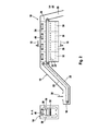
- FIG. 1 A second variant of the apparatus 12 is shown in FIG.
- axial fans 34 are used.
- the second variant differs from that shown in Figure 1 in that a returning belt 42 of the second conveyor belt 26 is disposed below the axial fans 34 and therefore is not flowed through.
- the internal circulation of the gas is shown in the sectional view 14 by the arrows 38.
- FIG. 4 shows a schematic representation of the process chamber 24 of the apparatus 12. Arranged thereon are a sensor 44 and a controllable valve 46.
- a boundary layer 48 is formed between the steam atmosphere 50 and the ambient air 52 due to a density difference.
- the drying process evaporates moisture from the dry material.
- a sensor signal 54 opens the valve 46 or puts a condenser (not shown in the figure) into operation. As a result, excess steam is removed from the process space 24 and the boundary layer 48 moves upward again.
- FIGS. 5 and 6 A second possibility according to the invention for separating steam is shown in FIGS. 5 and 6. Shown therein is a cross section 14 through the process space 24 with the second conveyor belt 26 arranged therein. Not shown are means for circulation and the means for heating the gas.
- a vertically disposed, insulated partition 58 separates the second conveyor from a condenser 56 disposed behind the partition 58.
- the condenser 56 is shown in Figs. 5 and 6 as a tube heat exchanger, but cold surfaces of a different design may also be used. Also conceivable is an arrangement of the condenser 56 and the partition wall 58 below the second conveyor belt 26, as shown in FIG. In both cases, the partition works as a weir.
- boundary layer 48 sinks to a level below the dividing wall 58 due to the increasing amount of steam, steam flows to the condenser 56 and is condensed there until the boundary layer 48 has again set to a level above the lower edge of the dividing wall 56.
- FIG. 7 A third arrangement variant according to the invention of the condenser 56 is shown in FIG. 7.
- the condenser 56 is arranged above the inclined plane 22.
- the partition 58 divides the condenser 56 from the process space 24. If the boundary layer 48 between the vapor atmosphere 50 and the ambient air 52 moves below the level of the dividing wall 58 due to the increase in steam, the vapor flows past the dividing wall 58 to the condenser 56 and is condensed there. Thus, the amount of steam in the process chamber 24 is reduced and the boundary layer 48 moves back up.
Landscapes
- Engineering & Computer Science (AREA)
- Mechanical Engineering (AREA)
- General Engineering & Computer Science (AREA)
- Drying Of Solid Materials (AREA)
Abstract
L'invention concerne un dispositif (129) de séchage au moyen d'un gaz chaud, de préférence de la vapeur d'eau surchauffée, qui comprend des moyens pour faire circuler (34, 40) ledit gaz et des moyens pour chauffer (32) ledit gaz ainsi que des moyens pour précipiter la vapeur excédentaire, qui sont disposés dans un espace de traitement (24). Selon l'invention, le gaz n'est pas prélevé dans l'espace de traitement pour la circulation, le chauffage ou la séparation de vapeur excédentaire et les moyens de chauffage du gaz sont situés en dessous du produit à sécher.
Applications Claiming Priority (2)
| Application Number | Priority Date | Filing Date | Title |
|---|---|---|---|
| DE102010032141.9 | 2010-07-24 | ||
| DE102010032141A DE102010032141A1 (de) | 2010-07-24 | 2010-07-24 | Apparat zur Trocknung mittels eines heißen Gases |
Publications (1)
| Publication Number | Publication Date |
|---|---|
| WO2012016807A1 true WO2012016807A1 (fr) | 2012-02-09 |
Family
ID=44629067
Family Applications (1)
| Application Number | Title | Priority Date | Filing Date |
|---|---|---|---|
| PCT/EP2011/062169 Ceased WO2012016807A1 (fr) | 2010-07-24 | 2011-07-15 | Dispositif de séchage au moyen d'un gaz chaud |
Country Status (2)
| Country | Link |
|---|---|
| DE (1) | DE102010032141A1 (fr) |
| WO (1) | WO2012016807A1 (fr) |
Cited By (4)
| Publication number | Priority date | Publication date | Assignee | Title |
|---|---|---|---|---|
| CN105004169A (zh) * | 2015-08-14 | 2015-10-28 | 吉首大学 | 锥斗式穿透逆流烘干机 |
| US10006714B2 (en) | 2007-08-07 | 2018-06-26 | Mars, Incorporated | Apparatus for drying a material |
| CN110926185A (zh) * | 2019-12-09 | 2020-03-27 | 程成 | 一种秸秆拌料烘干装置 |
| WO2021239749A1 (fr) | 2020-05-27 | 2021-12-02 | Climeworks Ag | Procédés et dispositif pour la capture de dioxyde de carbone entrainée par la vapeur |
Families Citing this family (2)
| Publication number | Priority date | Publication date | Assignee | Title |
|---|---|---|---|---|
| CN112556319B (zh) * | 2020-12-24 | 2025-11-18 | 青岛零壹叁装备科技有限公司 | 洗箱机用多级风干设备 |
| CN119309396B (zh) * | 2024-12-12 | 2025-03-18 | 广州凯能电器科技有限公司 | 一种橡胶烘干线 |
Citations (6)
| Publication number | Priority date | Publication date | Assignee | Title |
|---|---|---|---|---|
| DE1114148B (de) * | 1957-11-27 | 1961-09-21 | Schilde Maschb Ag | Flachbahn-Durchlueftungstrockner |
| FR1374869A (fr) * | 1963-11-19 | 1964-10-09 | Friedrich Haas Gmbh & Co Masch | Dispositif de traitement, en particulier de séchage de matière incohérente |
| WO1993003620A1 (fr) * | 1991-08-21 | 1993-03-04 | Bühler AG Maschinenfabrik | Procede et dispositif de moulage par compression et de sechage de pates alimentaires |
| EP0714498B1 (fr) | 1993-08-26 | 1997-10-29 | Heat-Win Limited | Appareil de sechage en continu dans la vapeur surchauffee |
| GB2378498A (en) * | 2001-08-11 | 2003-02-12 | Thomas John Stubbing | Thermal processing of organic material |
| WO2009018997A1 (fr) | 2007-08-07 | 2009-02-12 | Mars Incorporated | Procédé et appareil pour sécher un matériau extrudé |
Family Cites Families (3)
| Publication number | Priority date | Publication date | Assignee | Title |
|---|---|---|---|---|
| US4467532A (en) * | 1983-01-06 | 1984-08-28 | Drake Harry W | Apparatus and process for drying lumber |
| DE8313760U1 (de) * | 1983-05-09 | 1983-12-22 | Brückner Trockentechnik GmbH & Co KG, 7250 Leonberg | Heissluftbehandlungsvorrichtung fuer kontinuierlich transportiertes textilgut |
| DE3616966A1 (de) * | 1986-05-20 | 1987-11-26 | Dornier Gmbh Lindauer | Trockner fuer ein in kontinuierlicher bahn durchgefuehrtes gut |
-
2010
- 2010-07-24 DE DE102010032141A patent/DE102010032141A1/de not_active Ceased
-
2011
- 2011-07-15 WO PCT/EP2011/062169 patent/WO2012016807A1/fr not_active Ceased
Patent Citations (6)
| Publication number | Priority date | Publication date | Assignee | Title |
|---|---|---|---|---|
| DE1114148B (de) * | 1957-11-27 | 1961-09-21 | Schilde Maschb Ag | Flachbahn-Durchlueftungstrockner |
| FR1374869A (fr) * | 1963-11-19 | 1964-10-09 | Friedrich Haas Gmbh & Co Masch | Dispositif de traitement, en particulier de séchage de matière incohérente |
| WO1993003620A1 (fr) * | 1991-08-21 | 1993-03-04 | Bühler AG Maschinenfabrik | Procede et dispositif de moulage par compression et de sechage de pates alimentaires |
| EP0714498B1 (fr) | 1993-08-26 | 1997-10-29 | Heat-Win Limited | Appareil de sechage en continu dans la vapeur surchauffee |
| GB2378498A (en) * | 2001-08-11 | 2003-02-12 | Thomas John Stubbing | Thermal processing of organic material |
| WO2009018997A1 (fr) | 2007-08-07 | 2009-02-12 | Mars Incorporated | Procédé et appareil pour sécher un matériau extrudé |
Cited By (5)
| Publication number | Priority date | Publication date | Assignee | Title |
|---|---|---|---|---|
| US10006714B2 (en) | 2007-08-07 | 2018-06-26 | Mars, Incorporated | Apparatus for drying a material |
| US10113794B2 (en) | 2007-08-07 | 2018-10-30 | Mars, Incorporated | Method for drying a material |
| CN105004169A (zh) * | 2015-08-14 | 2015-10-28 | 吉首大学 | 锥斗式穿透逆流烘干机 |
| CN110926185A (zh) * | 2019-12-09 | 2020-03-27 | 程成 | 一种秸秆拌料烘干装置 |
| WO2021239749A1 (fr) | 2020-05-27 | 2021-12-02 | Climeworks Ag | Procédés et dispositif pour la capture de dioxyde de carbone entrainée par la vapeur |
Also Published As
| Publication number | Publication date |
|---|---|
| DE102010032141A1 (de) | 2012-01-26 |
Similar Documents
| Publication | Publication Date | Title |
|---|---|---|
| EP2516949B1 (fr) | Procédé et dispositif de séchage de plaques de plâtre | |
| WO2012016807A1 (fr) | Dispositif de séchage au moyen d'un gaz chaud | |
| AT515466B1 (de) | Verfahren zur Trocknung von Schüttgut | |
| DE102013206272B3 (de) | Bandtrockner mit einem Trocknungsraum und mit einer Kühlkammer | |
| DE102016213956B4 (de) | Kontakttrockner | |
| EP3333524B1 (fr) | Séchoir continu permettant le séchage d'un objet par air chaud doté d'au moins deux sections | |
| EP3396285B1 (fr) | Séchoir continu pourvu d'un échangeur thermique | |
| WO2014166830A1 (fr) | Séchoir à bande transporteuse comportant une chambre de séchage | |
| EP2418431B1 (fr) | Dispositif de climatisation doté d'un dispositif de conditionnement de l'air | |
| DE2706162A1 (de) | Anlage zur fortlaufenden waermebehandlung eines eine kammer durchlaufenden behandlungsgutes | |
| WO2017133727A1 (fr) | Sécheur continu comportant au moins deux sections | |
| DE2611853A1 (de) | Verfahren zum trocknen landwirtschaftlicher futtermittel und schlammartiger materialien | |
| EP0356388A2 (fr) | Procédé et dispositif pour déshydrater des masses aqueuses | |
| DE4207266B4 (de) | Dünnschichtverdampfer | |
| DE69938417T2 (de) | Verfahren und vorrichtung zur entfernung von flüssigkeit aus teilchenförmigem material | |
| WO2016128455A1 (fr) | Installation de distillation à étages multiples, procédé permettant de faire fonctionner une installation de ce type | |
| DE1145530B (de) | Vorrichtung zur Befeuchtung von Tabak u. dgl. | |
| DE19928064C5 (de) | Verfahren und Vorrichtung zum Eindampfen bzw. Verdampfen von Flüssigkeiten | |
| EP4587766A1 (fr) | Procédé de fonctionnement d'une installation de séchage de matériau par vapeur surchauffée | |
| DE69800889T2 (de) | Verfahren zum betreiben einer trocknungsvorrichtung, sowie eine vorrichtung zur durchführung dieses verfahrens | |
| EP0091451A4 (fr) | Procede et dispositif de sechage a petite consommation d'energie, en particulier de produits granuleux, agricoles ou autres contenant de l'humidite fixee ou deposee a la surface, a rendement constant. | |
| DE102017108695B4 (de) | Durchlauftrockner mit einer ersten und einer zweiten Sektion | |
| DE102012105427B3 (de) | Verfahren und Anlage zur Verarbeitung eines feuchten, Kerogen enthaltenden Stoffstroms | |
| DE102019114467A1 (de) | Verfahren zur Entschwadung von Prozessabluft | |
| DE102016103685C5 (de) | Durchlauftrockner mit mindestens zwei Sektionen |
Legal Events
| Date | Code | Title | Description |
|---|---|---|---|
| 121 | Ep: the epo has been informed by wipo that ep was designated in this application |
Ref document number: 11736049 Country of ref document: EP Kind code of ref document: A1 |
|
| NENP | Non-entry into the national phase |
Ref country code: DE |
|
| 122 | Ep: pct application non-entry in european phase |
Ref document number: 11736049 Country of ref document: EP Kind code of ref document: A1 |