WO2012017603A1 - Dispositif de reproduction, circuit intégré, procédé de reproduction et programme - Google Patents
Dispositif de reproduction, circuit intégré, procédé de reproduction et programme Download PDFInfo
- Publication number
- WO2012017603A1 WO2012017603A1 PCT/JP2011/003962 JP2011003962W WO2012017603A1 WO 2012017603 A1 WO2012017603 A1 WO 2012017603A1 JP 2011003962 W JP2011003962 W JP 2011003962W WO 2012017603 A1 WO2012017603 A1 WO 2012017603A1
- Authority
- WO
- WIPO (PCT)
- Prior art keywords
- stream
- subtitle
- layout
- plane
- playback
- Prior art date
- Legal status (The legal status is an assumption and is not a legal conclusion. Google has not performed a legal analysis and makes no representation as to the accuracy of the status listed.)
- Ceased
Links
Images



















Classifications
-
- H—ELECTRICITY
- H04—ELECTRIC COMMUNICATION TECHNIQUE
- H04N—PICTORIAL COMMUNICATION, e.g. TELEVISION
- H04N21/00—Selective content distribution, e.g. interactive television or video on demand [VOD]
- H04N21/40—Client devices specifically adapted for the reception of or interaction with content, e.g. set-top-box [STB]; Operations thereof
- H04N21/47—End-user applications
- H04N21/488—Data services, e.g. news ticker
- H04N21/4884—Data services, e.g. news ticker for displaying subtitles
-
- H—ELECTRICITY
- H04—ELECTRIC COMMUNICATION TECHNIQUE
- H04N—PICTORIAL COMMUNICATION, e.g. TELEVISION
- H04N13/00—Stereoscopic video systems; Multi-view video systems; Details thereof
- H04N13/10—Processing, recording or transmission of stereoscopic or multi-view image signals
- H04N13/106—Processing image signals
- H04N13/156—Mixing image signals
-
- H—ELECTRICITY
- H04—ELECTRIC COMMUNICATION TECHNIQUE
- H04N—PICTORIAL COMMUNICATION, e.g. TELEVISION
- H04N13/00—Stereoscopic video systems; Multi-view video systems; Details thereof
- H04N13/10—Processing, recording or transmission of stereoscopic or multi-view image signals
- H04N13/106—Processing image signals
- H04N13/172—Processing image signals image signals comprising non-image signal components, e.g. headers or format information
- H04N13/183—On-screen display [OSD] information, e.g. subtitles or menus
-
- H—ELECTRICITY
- H04—ELECTRIC COMMUNICATION TECHNIQUE
- H04N—PICTORIAL COMMUNICATION, e.g. TELEVISION
- H04N21/00—Selective content distribution, e.g. interactive television or video on demand [VOD]
- H04N21/40—Client devices specifically adapted for the reception of or interaction with content, e.g. set-top-box [STB]; Operations thereof
- H04N21/43—Processing of content or additional data, e.g. demultiplexing additional data from a digital video stream; Elementary client operations, e.g. monitoring of home network or synchronising decoder's clock; Client middleware
- H04N21/431—Generation of visual interfaces for content selection or interaction; Content or additional data rendering
- H04N21/4312—Generation of visual interfaces for content selection or interaction; Content or additional data rendering involving specific graphical features, e.g. screen layout, special fonts or colors, blinking icons, highlights or animations
Definitions
- the present invention belongs to the technical field of stereoscopic reproduction technology.
- Stereoscopic playback technology refers to a technology that artificially creates a stereoscopic image by introducing a mechanism to show different pictures for the left and right eyes and using the parallax between the eyes.
- stereoscopic displays for allowing the user to view stereoscopic images.
- one of the commonly used methods is a method using shutter glasses.
- the viewer's left eye and right eye fields of view are alternately covered with glasses at high speed, and the display image on the display is updated at high speed for the left and right eyes in synchronization with the operation of the glasses.
- the left-eye image displayed on the display as a result can be seen only by the shutter glasses, while the right-eye image can be seen only by the right eye.
- the stereoscopic image is converted into a planar image, and then used for composition with OSD (On Screen Display), which is a GUI built in the device, so it is possible to avoid biting into the stereoscopic image as described above. it can.
- OSD On Screen Display
- the playback device is a player that plays back a Blu-Ray disc, as described in Patent Document 2, a value that represents the position in the depth direction of the 3D image recorded on the BD, It is also conceivable that the value representing the farthest position is set in PSR (Player Setting Register) and the OSD is placed at the near side or the far side position.
- PSR Player Setting Register
- the OSD is expressed in the moving image and bites into the three-dimensional object.
- the OSD is located at the frontmost position or the innermost side of the depth of the three-dimensional object. Is placed.
- the OSD When the position on the front side is selected as the position in the depth direction of the OSD, if the OSD plane position on the screen and the plane position of the three-dimensional object on the screen overlap during stereoscopic playback, the OSD is pasted on the stereoscopic image. Therefore, it cannot be distinguished whether the OSD is an object in a movie work or an OSD displayed for user feedback. Conversely, when the farthest position is selected as the position in the depth direction of the OSD, if the OSD plane position on the screen and the plane position of the three-dimensional object on the screen overlap during stereoscopic playback, the OSD Depending on the location of the OSD, the OSD will be hidden by a three-dimensional object, and it will be impossible to visually recognize what the OSD is.
- An object of the present invention is to provide a playback device capable of coexistence of a device-embedded GUI incorporated in a device uniquely created by a manufacturer and a stereoscopic image created by a content provider.
- a playback apparatus provides: A video decoder that decodes a stereoscopic video stream to perform stereoscopic playback; A subtitle decoder that decodes the subtitle stream and displays subtitles in a predetermined layout; A drawing means for drawing a built-in GUI; Comprising a synthesizing means for synthesizing stereoscopic playback by a video decoder, subtitle display, and a drawn device-embedded GUI;
- the subtitle layout includes a normal layout, an upper end arrangement layout that secures a subtitle display area only on the upper end side of the screen, and a lower end arrangement layout that reserves a subtitle display area only on the lower end side of the screen,
- the drawing unit includes a layout selection unit that selects the same layout as the layout of the GUI embedded in the device if the top layout or the bottom layout is selected as the subtitle layout. It is characterized by that.
- the same layout as the subtitle layout is selected as the built-in GUI layout, so the built-in GUI and the subtitle must be placed in the same display area. become.
- the layout and arrangement position of such subtitles do not overlap with moving images and are determined at the time of authoring so that they are easy to see. If the same layout as subtitles is applied to the built-in GUI, the GUI will not overlap with the stereoscopic image That is guaranteed.
- the same layout as the subtitle layout is selected as the built-in GUI layout, so the built-in GUI and the subtitle must be placed in the same display area. Therefore, only the built-in GUI is not placed at the position where it overlaps with the moving image.
- GUI display quality control is possible, a GUI that is convenient for the manufacturer can be displayed in the stereoscopic mode, improving the convenience and functionality of the playback device, and realizing differentiation from other companies' products. it can.
- the playback device that solves the above-described problem may be one of the following modes 1), 2), 3),...
- the playback device includes a right-eye video plane, a left-eye video plane, and a shift unit.
- the video decoder decodes the stereoscopic video stream to obtain a set of left-eye picture data and right-eye picture data, and writes them to the right-eye video plane and the left-eye video plane,
- the shift unit may shift the picture data stored in the video plane downward in the top layout, and shift the picture data stored in the video plane upward in the bottom layout.
- the vertical shift of the video plane can be realized by moving the pixel position stored in the video plane in the vertical direction, the vertical shift of the video plane can arbitrarily change the layout of the video plane. it can. Such movement of the pixel position is sufficient if the address of the pixel data stored in the video plane is changed, and the addition of hardware processing is minimal. Therefore, the video plane layout can be changed at a low development cost.
- the playback apparatus includes a plane memory that stores pixel data that configures subtitles and pixel data that configures a device-embedded GUI,
- the display mode of the caption decoder and the drawing means includes a one-plane offset mode and a planar view mode,
- the one plane offset mode is a playback mode that realizes stereoscopic playback by giving a horizontal offset to the coordinates of pixel data in a plane memory
- the drawing means includes a GUI depth adjustment unit that adjusts the depth of the built-in GUI when displaying the built-in GUI in the one-plane offset mode.
- the GUI depth adjustment unit may employ a horizontal offset when displaying subtitles in the one-plane offset mode as a horizontal offset when displaying a built-in GUI in the one-plane offset mode.
- the horizontal offset when displaying in the one-plane offset mode can be obtained in real time from the video decoder as an information element for stereoscopic playback, so the offset obtained from the video decoder can be used for GUI depth adjustment. If used, the depth of the GUI can be adjusted so that it is about the same depth as the subtitles. In addition, even if the depth on the caption side changes momentarily as the time axis of the moving image progresses, the depth of the GUI can be made to follow the depth on the caption side. This enables stereoscopic control with control over the entire movie work.
- the GUI depth adjustment unit The shift direction when displaying subtitles in the one-plane offset mode may be adopted as the shift direction when displaying the built-in GUI in the one-plane offset mode.
- the GUI layout follows the subtitle side position. Can be made. This enables stereoscopic control with control over the entire movie work.
- the drawing means further includes A special subtitle determination unit that determines whether or not the subtitle stream to be played is a special subtitle having more characters than a normal subtitle, In the upper end arrangement layout or the lower end arrangement layout, a margin area detection unit that detects a margin area of a caption area secured at the upper end or lower end of the screen; An arrangement determining unit that determines the arrangement position of the GUI embedded in the device, When the special subtitle determination unit determines that the subtitle stream is a special subtitle, the arrangement determination unit may determine the arrangement position of the device-embedded GUI in the blank area detected by the blank area detection unit.
- the special subtitle determination unit determines that the subtitle stream is a special subtitle
- the placement position of the device built-in GUI is determined in the margin area, so the subtitle with a large number of characters and the device built-in GUI are displayed in duplicate. The possibility of being done can be eliminated as much as possible. Therefore, it is possible to realize an easy-to-view screen layout that does not depend on whether or not the selected subtitle stream is a special subtitle.
- a stream selection table is recorded on the recording medium, and the stream selection table indicates the priority order of the subtitle stream in association with the language attribute of the subtitle stream,
- the special caption determination unit Two or more subtitle streams having the same language attribute, the priority of which is set to the second or lower in the stream selection table, may be determined as a subtitle stream for a special subtitle.
- the special subtitle stream is determined as a special subtitle stream according to the rule of thumb of movie authoring that the second or later priority is entered in the stream selection table.
- the determination accuracy is guaranteed with a high probability. Further, such a determination can be realized by static analysis of navigation information called a stream selection table. Therefore, it is possible to determine whether or not the subtitle stream is a special subtitle stream by implementation with simple software.
- the arrangement of subtitles in the subtitle area in the upper end arrangement layout or the lower end arrangement layout is any of right side, left side, and center alignment,
- the detection of the blank area by the blank area detection unit is performed based on the arrangement of the subtitles in the subtitle area and the number of characters of the subtitles.
- the drawing means further comprises a reduction unit for reducing the device built-in GUI to be displayed in the caption area,
- the reduction of the device-embedded GUI by the reduction unit may be performed when the display size of the device-embedded GUI exceeds the margin of the caption area.
- the subtitle arrangement position can be determined with high accuracy by statically analyzing the information elements of the subtitle stream.
- Such static analysis of a subtitle stream can be realized by an extension of software development of an existing subtitle stream decoder, so that it can be easily implemented in an existing playback device.
- FIG. 1 shows an internal configuration of a recording medium according to a first embodiment.
- the internal structure of playlist information is shown.
- An example of a basic stream selection table is shown.
- the internal structure of the extension data of playlist information is shown.
- the internal structure of the stream registration sequence of the PG stream in the extended stream selection table and the in-plane validation information is shown.
- regenerating apparatus is shown.
- 3 is a diagram showing an internal configuration of PSR2 and PSR22.
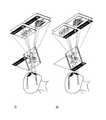
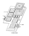
- a stereoscopic image obtained by layer composition is shown. This shows the layer composition of the video plane contents shifted upward and the graphics plane.
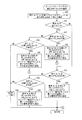
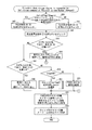
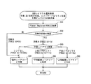
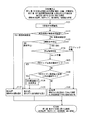
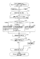
- the playlist playback procedure is shown. It is a flowchart which shows the process sequence about Procedure when playback condition is changed about PG_text subtitle stream. It is a flowchart which shows the process sequence which selects the optimal PG_text subtitle stream about a current play item. It is a flowchart which shows the processing procedure of Procedure
- the internal structure of the PG decoder is shown.
- the internal structure of a text subtitle decoder is shown.
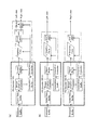
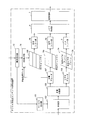
- a circuit configuration for synthesizing and outputting the outputs of the decoder model is shown.
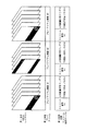
- In the text subtitle stream it shows how the syntax for defining a plurality of area information and the right end coordinates of the area occupied by the text character string are determined by each of the plurality of areas in the graphics plane.
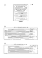
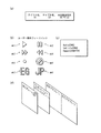
- the case where OSD is arranged at the top of the screen with various layouts is shown. It is a figure supposing the case where a subtitle is SDH.
- FIG. 2 shows an internal structure of a transport stream for supplying 3D digital broadcast content to a playback device. It shows the internal structure of a caption stream, PCS, RCS, caption information table, and in-plane activation information. It is a functional block diagram which shows the structure of the reproducing
- the invention of the playback device, the invention of the integrated circuit, and the invention of the playback method included in the present application can be implemented as a player device corresponding to a package medium.
- a description will be given of an embodiment of a playback apparatus provided with the above-described problem solving means.
- FIG. 1 is a diagram showing a home theater system including a player device.
- This system includes a recording medium 100 as a package medium, a playback device 200 as a player device, an operation device 300, a television 400, and liquid crystal glasses 500.
- the recording medium 100 supplies, for example, a movie work to the home theater system.
- (1-2) Playback device 200 The playback device 200 is connected to the television 400 and plays back the recording medium 100.
- the reproduced video reproduced in this way includes 2D video and 3D video.
- 2D video is an image expressed by pixels on the X-Y plane when the display screen of the display device is regarded as the X-Y plane, and is also called a planar view image.
- 3D video is an image obtained by adding the depth in the Z-axis direction to the pixels on the XY plane on the screen of the display device.
- the 3D image is played back by the user by reproducing both the left-eye image incident on the left-eye pupil and the right-eye image incident on the right-eye pupil and exerting a stereoscopic effect on the left-eye image and the right-eye image. Is done.
- the user feels that the pixel having the positive Z-axis coordinate is in front of the screen of the display device, and feels that the pixel having the negative Z-axis coordinate exists behind the screen.
- the remote controller 300 is a device that accepts an operation on a hierarchical GUI from a user. To accept such an operation, the remote controller 100 moves a menu key for calling a menu constituting the GUI and a focus of a GUI component constituting the menu. An arrow key, a determination key for performing a confirmation operation on a GUI component constituting the menu, a return key for returning a hierarchical menu to a higher level, and a numerical key are provided.
- the television 400 provides a user with an interactive operation environment by displaying a playback image of a movie work or displaying a menu or the like.
- LCD glasses 500 The liquid crystal glasses 500 include a liquid crystal shutter and a control unit, and realize stereoscopic viewing using parallax between both eyes of the user.
- the liquid crystal shutter of the liquid crystal glasses 500 is a shutter using a liquid crystal lens having a property that light transmittance is changed by changing an applied voltage.
- the control unit of the liquid crystal glasses 500 receives a synchronization signal for switching the output of the image for incidence on the right eye pupil and the image for incidence on the left eye pupil sent from the playback device, and in accordance with this synchronization signal, the first state, The second state is switched.
- the first state is a state in which the applied voltage is adjusted so that the liquid crystal lens for the right eye does not transmit light and the applied voltage is adjusted so that the liquid crystal lens for the left eye transmits light. In this state, the left eye image Is provided for viewing, and the left eye image cannot be seen with the right eye.
- the second state is a state in which the applied voltage is adjusted so that the liquid crystal lens for the right eye transmits light, and the applied voltage is adjusted so that the liquid crystal lens for the left eye does not transmit light.
- the incident image is provided for viewing, and the incident image to the left eye cannot be seen.
- FIG. 2 shows how the picture data for the left eye and the picture data for the right eye looks by the user wearing the shutter glasses 500.
- the arrow vw1 in the figure indicates the video input to the pupil during the entrance period to the left eye pupil
- the arrow vw2 in the figure indicates the video input to the pupil during the entrance period to the right eye pupil.
- the incident period to the left eye pupil as shown by the arrow vw1
- the stored content of the left eye picture data is incident on the user's left eye pupil through the shutter glasses 500.
- the incident period to the right eye pupil the stored content of the right eye picture data enters the user's right eye pupil through the shutter glasses 500 as indicated by the arrow vw2.
- Playback mode for 3D video playback There are two types of 3D video played back by the home theater system, one played in a playback mode called “stereoscopic mode” and one played in a playback mode called “1 plane + offset mode”.
- the stereoscopic mode is a playback mode that realizes a stereoscopic view by simultaneously playing a base-view video stream and a dependent-view stream defined by the Multiview Video Coding standard.
- the Multiview Video Coding (MVC) standard is an amended standard for MPEG-4 AVC / H.264 and was formulated by the Joint Video Team (JVT), a joint project of ISO / IEC MPEG and ITU-T VCEG.
- JVT Joint Video Team
- videos from multiple viewpoints can be encoded together, and not only the temporal similarity of video but also the similarity between viewpoints is used for predictive coding, so multiple viewpoints can be compressed independently. Compared to the above, the compression efficiency is improved.
- the base-view video stream is a sub-bitstream whose view_id is 0 and a sequence of view components whose view_id is 0.
- the MPEG-4 MVC base-view video stream obeys the restrictions of the MPEG-4 AVC video stream.
- the dependent-view video stream is a sub-bitstream whose view_id is 1, and a sequence of view components whose view_id is 1.
- (2-1-3) View component A plurality of base view components constituting the base view video stream are described inside the base view video stream. In addition, a plurality of dependent view components constituting the dependent view stream are described inside the dependent view stream. These base view component and dependent view component have picture types such as IDR, B, and P.
- a view component refers to each of a plurality of picture data that is simultaneously played back for stereoscopic playback in one frame period. Compression encoding using the correlation between viewpoints is achieved by using the view components of the base-view video stream and the dependent-view video stream as picture data and realizing compression encoding using the correlation between pictures. Made.
- a combination of the view component of the base view video stream and the view component of the dependent view video stream allocated in one frame period constitutes one access unit, and this access unit is random. Access is possible.
- Each of the base-view video stream and the dependent-view video stream has a GOP structure in which each view component is a “picture”, and includes a closed GOP and an open GOP.
- the closed GOP is composed of an IDR picture, a B picture following the IDR picture, and a P picture.
- the open GOP is composed of a Non-IDR I picture, a B picture following the Non-IDR I picture, and a P picture.
- the incident image to the left eye pupil and the incident image to the right eye pupil as shown in FIG. 2 are made by simultaneously reproducing the base view video stream and the dependent view stream.
- the 1 plane + Offset mode is a playback mode that realizes stereoscopic viewing by incorporating a shift unit in the subsequent stage of the plane memory and causing the shift unit to function.
- the plane offset unit shifts the pixel coordinates of the line unit in the plane memory in the left direction or the right direction in each of the incident period to the left eye pupil and the incident period to the right eye pupil, and forms an image of the right visual line and the left visual line
- the sense of depth is changed by displacing the point toward the front or the depth.
- the image point of the line of sight of both eyes will be closer to the front, If the pixel coordinates are changed rightward during the incident period and leftward during the incident period to the right-eye pupil, the image point of the line of sight of both eyes will be in front.
- This plane shift is ideal for easily creating stereoscopic images because only one plane memory is required for stereoscopic viewing.
- This plane shift is only suitable for stereoscopic effects such as menus and subtitles because it only produces a stereoscopic image in which a planar image comes to the front or pulls in the back. This is somewhat unsatisfactory for realizing the stereoscopic effect. This is because the indentation and unevenness of the character's face cannot be reproduced.
- the playback device configuration When supporting 1 plane + Offset mode, the playback device configuration is as follows.
- the playback apparatus includes a plane memory, a CLUT unit, and a synthesis unit, and a plane shift unit is incorporated between the CLUT unit and the synthesis unit.
- a shift part implement achieves the coordinate change of a pixel as mentioned above using the offset in the offset sequence integrated in the access unit structure of dependent view video stream. By doing so, the degree of pixel projection in the 1 plane + offset mode is precisely synchronized with the MVC video stream.
- the plane memories to be subjected to shift control by the offset sequence are a plurality of plane memories that constitute a predetermined layer model.
- the plane memory is a memory for storing pixel data for one screen in units of lines and outputting the pixel data along the horizontal synchronization signal and the vertical synchronization signal.
- the plain memory stores the pixel data for one screen obtained by decoding of the video decoder and presentation graphics (PG) decoder, and the pixel data for one screen created to draw OSD (On Screen Display). .
- OSD is one of the device-embedded GUIs created by the manufacturer in the playback device.
- the predetermined layer model is composed of a left-eye video plane layer, a right-eye video plane layer, a PG plane layer, and a GFX plane layer.
- the contents stored in the plane memory of each layer are represented by the left-eye video plane ⁇ PG plane ⁇ GFX It is intended to combine layers in the order of planes.
- the process of superimposing the pixel values of the pixel data stored in the plane memory of the two layers is executed for all combinations of the two layers in the layer model. That is done.
- the plain memory of each layer will be described.
- the left-eye video plane is a plane memory that can store pixel data for one screen obtained by decoding the view components constituting the base-view video stream.
- the right-eye video plane is a plane memory that can store pixel data for one screen obtained by decoding the view components that make up the dependent-view video stream.
- the presentation graphics (PG) plane is a plane memory used for storing graphics obtained by a decoding process performed by a graphics decoder operating in a pipeline manner.
- the GFX plane is a plane memory used for OSD drawing.
- the GFX and PG planes are for the base view and the dependent view.
- the GFX plane and PG plane are subject to shift control.
- FIG. 3 is a diagram illustrating an example of a difference in appearance between positive and negative plane offsets.
- (A) and (b) in the same figure show the right-view graphics image output using the shifted graphics plane shifted at the time of right-view output.
- the far side shows the graphics image for incidence on the left eye pupil that is output using the shifted graphics plane that is shifted at the time of incidence output to the left eye pupil.
- This figure (a) shows the case where the sign of the plane offset is positive (the graphics image for incidence on the left eye pupil is shifted to the right and the graphics image for right view is shifted to the left).
- the plane offset is a positive value
- the caption at the time of incident output to the left eye pupil can be seen at the right position from the caption at the time of right view output. That is, since the convergence point (focus position) comes to the front of the screen, the subtitles can also be seen to the front.
- This figure (b) shows the case where the sign of the plane offset is negative. If it is a negative value, as shown in FIG. 14, the caption at the time of incident output to the left eye pupil can be seen at the left position from the caption at the time of output of the right view. In other words, since the convergence point (focus position) goes deeper than the screen, the subtitles can also be seen deeper.
- FIG. 4 shows a case where the sign of the plane offset is positive (the drawing image writing position during the incidence period to the left eye pupil is shifted to the right, and the writing image writing position during the incidence period to the right eye pupil is shifted to the left). It is a figure for demonstrating the principle that an image looks like it exists in front of a display screen.
- the image that is visible to the left eye is shifted and displayed so that it is visible on the right side compared to the case where the plane offset is zero. At this time, nothing is visible to the right eye by the shutter glasses 500. On the other hand, the image visible to the right eye is displayed so as to be shifted so that it can be seen on the left side as compared with the case where the plane offset is zero. At this time, nothing is visible to the left eye by the shutter glasses 500 (FIG. 4B).
- ⁇ Human uses both eyes to focus and recognizes that there is an image at the focal position. Therefore, when the shutter glasses 500 alternately switch between a state in which an image can be seen by the left eye and a state in which the image can be seen by the right eye at short time intervals, both eyes of the human will try to adjust the focal position to a position in front of the display screen. As a result, an illusion is caused so that an image is present at the focal position located in front of the display screen (FIG. 4C).
- FIG. 5 is a diagram for explaining the principle that an image appears to be behind the display screen.
- FIG. 5 what is indicated by a circle is an image displayed on the display screen.
- the image that can be seen by the right eye and the image that can be seen by the left eye are at the same position. Therefore, the focal position when the image is viewed using both eyes is located on the display screen (FIG. 5A). ). The resulting image is located on the display screen.
- the image visible to the left eye is made to appear on the left side as compared with the case where the plane offset is zero. At this time, nothing is visible to the right eye by the shutter glasses 500. On the other hand, the image that can be seen by the right eye is made to appear at the right position as compared with the case where the offset is “0”, and at this time, nothing is seen by the shutter glasses 500 by the left eye (FIG. 5B). .
- the human eyes try to adjust the focal position to a position deeper than the display screen.
- An illusion is caused so that there is an image at a position behind the display screen (FIG. 5C).
- the dependent view stream is different from the base view video stream in that an offset sequence used in the 1 plane + offset mode is incorporated.
- the offset sequence will be described.
- the video access unit of the dependent-view video stream is configured by arranging the video access unit delimiter, sequence parameter set, picture parameter set, MVC scalable nesting SEI message, first view component, sequence end code, stream end code Is done.
- a user data container exists in the MVC scalable nesting SEI message.
- the user data container is unregistered user data (unregistered user data), and there are three types: closed caption information, GOP structure map, and offset metadata. Which of these types is specified in type_ indicator in the container.
- the offset metadata must be stored in the MVC scalable nesting SEI message of the first video component of each GOP in the encoding order of the dependent view access unit.
- the offset sequence is a parameter sequence that indicates control parameters in the case of synthesizing each piece of picture data belonging to the group of pictures and graphics, and is composed of the number of control parameters indicated by number_of_displayed_frames_in_GOP.
- the This control parameter includes plane offset direction information and a plane offset value.
- the plane offset direction information indicates the offset direction in the plane.
- the value “0” is set to the front, that is, the plane memory exists between the TV and the viewer.
- the plane is in the right direction during the entrance period to the left eye pupil, and the plane is in the left direction during the entrance period to the right eye pupil. Shifted.
- the plane offset direction information indicates the front setting
- the Z-axis coordinate of the control parameter in the three-dimensional coordinate system is a positive coordinate.
- the plane offset direction information indicates behind setting, the Z-axis coordinate of the control parameter in the three-dimensional coordinate system is a negative coordinate.
- the plane offset value (Plane_offset_value) is a designation of the horizontal displacement amount of the pixels constituting the graphics, and indicates the plane offset value in units of pixels. This completes the description of the 1 plane + Offset mode.
- FIG. 6 shows an internal configuration of the recording medium according to the first embodiment.
- the recording medium according to the first embodiment includes “index table”, “program file of operation mode object”, “playlist information file”, “stream information file”, “stream”. File "is recorded.
- index table is management information relating to the entire recording medium, and the recording medium is uniquely recognized by the reproducing apparatus by first reading the index table after the recording medium is inserted into the reproducing apparatus.
- (3-2) Operation mode object program file The program file of the operation mode object stores a control program for operating the playback device.
- the program in this program file includes a program described by a command and a program described by an object-oriented compiler language.
- the former program supplies a plurality of navigation commands as a batch job to the playback device, and operates the playback device based on these navigation commands.
- This command-based operation mode is called “HDMV mode”.
- the latter program supplies a bytecode application, which is an instance of a class structure, to the playback device in the object-oriented compiler language-based operation mode, and operates the playback device based on this instance.
- a Java (TM) application which is one of bytecode applications, can be used as an instance of the class structure.
- the operation mode based on the object-oriented compiler language is called “BD-J mode”.
- the stream file stores a transport stream obtained by multiplexing a video stream, one or more audio streams, and a graphics stream.
- the 2D dedicated stream file has a normal transport stream format
- the 2D-3D combined stream file has a stereoscopic interleaved stream file format.
- the stereoscopic interleaved stream file format is an interleaved format of the extent of the main transport stream (main TS) including the base view stream and the extent of the sub transport stream (sub TS) including the dependent view video stream. Are arranged alternately.
- the main transport stream (TS) stored in the stream file has packet management information (PCR, PMT, PAT) defined in the European digital broadcasting standard as information for managing and controlling multiple types of PES streams. is doing.
- PCR, PMT, and PAT have a role to define a partial TS that constitutes one broadcast program (Program) in the European digital broadcasting standard, and the playback device constitutes one broadcast program in the European digital broadcasting standard.
- the TS can be used for processing by the decoder as if it were a partial TS. This is intended to be compatible with a European digital broadcasting standard terminal device and a recording medium playback device.
- the extent set in the main TS and the extent in the sub-TS are set to a data size that does not cause the double buffer to underflow during playback, and the playback device can read these extent sets seamlessly.
- the stream information file guarantees random access to an arbitrary source packet in the transport stream in the stream file and continuous reproduction with other transport streams. Through this stream information file, the stream file is managed as an “AV clip”.
- the stream information file is a basic entry map that indicates information such as the encoding format, frame rate, bit rate, resolution, etc. of the stream in an AV clip, and the source packet number at the head position of the GOP in association with the presentation time stamp of the frame period Therefore, if this stream information file is loaded into the memory before accessing the stream file, it can be understood what the transport stream in the stream file to be accessed is. , Random access execution can be guaranteed.
- the stream information file includes a 2D stream information file and a 3D stream information file.
- the 3D stream information file includes clip information for base view (clip base information) and clip information for dependent view ( Clip dependent information) and an extended entry map for stereoscopic viewing.
- the clip base information includes extent start point information for the base view, and the clip dependent information includes extent start point information for the dependent view.
- the extent start point information for the base view is composed of a plurality of source packet numbers. Each source packet number indicates in what packet the extent division position in the main TS exists.
- the extent start point information for the dependent view is also composed of a plurality of source packet numbers, and indicates how many packets have the division position in the sub-TS.
- Expansion entry map indicates the source packet number of the access unit delimiter that is the head position of the GOP head view component in the dependent-view video stream in association with the presentation time stamp representing the GOP head frame period.
- the basic entry map is compatible with the 2D stream information file, but is associated with the presentation time stamp representing the GOP head frame period, and is the access unit data that becomes the head position of the GOP head view component in the base view video stream. Indicates the limiter source packet number.
- the playlist information file is a file that stores information for causing the playback device to play back the playlist.
- a “playlist” is a playback path defined by specifying playback sections on the time axis of the transport stream (TS) and logically specifying the playback order between the playback sections. Of these, it plays the role of defining which part is played back and in what order the scene is developed.
- the playlist information defines the “type” of the playlist.
- the playback path defined by the playlist information is a so-called “multipath”. Multipath is a bundle of a playback path (main path) defined for a main TS and a playback path (subpath) defined for a subordinate TS. If the playback path of the base-view video stream is defined in this multi-pass and the playback path of the dependent-view video stream is defined in the sub-path, the combination of video streams for reproducing stereoscopic vision can be preferably defined. it can.
- An application based on an object-oriented programming language orders the generation of a framework player instance that reproduces this playlist information, so that AV reproduction by multipass can be started.
- the framework player instance is actual data generated on the heap memory of the virtual machine based on the media framework player class.
- the command-based program can also start playback by multipass by issuing a playback command specifying this playlist information as an argument.
- FIG. 5B shows a plurality of elementary streams constituting the main TS
- FIG. 5C shows a plurality of elementary streams constituting the sub-TS.
- the main TS includes one base-view video stream, 32 left-eye PG streams, 32 left-eye interactive graphics (IG) streams, and 32 audio streams.
- the sub-TS includes one dependent-view video stream, 32 right-eye PG streams, and 32 right-eye IG streams.
- the elementary stream (ES) multiplexed in the TS includes an audio stream, a presentation graphics stream, and an interactive graphics stream in addition to the above-described base-view video stream and dependent-view video stream.
- Audio stream There are two types of audio streams, a primary audio stream and a secondary audio stream.
- the primary audio stream is an audio stream that should be a main sound when mixing reproduction is performed
- the secondary audio stream is an audio stream that should be a sub sound when mixing reproduction is performed.
- the secondary audio stream includes information for downsampling for mixing and information for gain control.
- the PG stream is a graphics stream suitable for subtitle display that can be precisely synchronized with video by adopting a pipeline in the decoder.
- Up to 32 2DPG streams, up to 32 left-eye PG streams, and up to 32 right-eye PG streams can be defined. Each of these PG streams is provided with a different packet identifier. By instructing the demultiplexer to specify a packet identifier to be reproduced, a desired one of these PG streams is provided for reproduction. Will be.
- PG stream is not limited to character reproduction like subtitles. Any graphics playback that requires precise synchronization, such as displaying a mascot character of a movie work and synchronizing it with a moving image, should be adopted as a playback target by the PG stream. Can do.
- -Streams that are not multiplexed into a stream file but show subtitles include text subtitle (textST) streams in addition to PG streams.
- the textST stream is a stream that represents the content of subtitles in character code.
- the PG stream and the text subtitle stream are registered in the same stream registration column on the assumption that these types are not distinguished and are the same stream type. Then, when executing the stream selection procedure, the PG stream or text subtitle stream to be reproduced is determined according to the stream registration order in the stream registration sequence. Since the PG stream and the text subtitle stream are provided to the stream selection procedure without distinguishing the stream type, the PG stream and the text subtitle stream are classified into one stream type, that is, “PG_text subtitle stream (abbreviated, It may be called a subtitle stream) ”.
- the PG_text subtitle stream for 2D is played back in 1plane + Offset mode.
- the 2DPG_text subtitle stream is a 1 plane + OffsetPG_text subtitle stream.
- the IG stream is a graphics stream that can display a menu as the video stream is played back and can display a pop-up menu according to a user operation by including information on an interactive operation.
- the significance of the IG stream having dialogue operation information is as follows.
- the Java virtual machine instructs the playback control engine, which is the main player of playback control, to start playback of a playlist in response to a request from the application
- the Java virtual machine instructs the playback control engine to play, and then plays the playlist. Returns a response indicating that it has started to the application.
- the Java virtual machine does not wait for execution completion. This is because the Java virtual machine is a so-called event-driven operating entity and can operate while the playback control engine is playing back a playlist.
- the command interpreter when the command interpreter commands the playback control engine to play a playlist, it waits for completion of the playlist playback until the playlist playback ends. While playback by the playback control engine continues, the command execution unit cannot execute interactive processing. Instead of this command interpreter, the graphics decoder performs an interactive operation. In order to cause the graphics decoder to perform an interactive operation, control information defining an interactive operation using a button member is incorporated in the IG stream. *
- the playlist information has an internal configuration as shown in FIG. FIG. 7 shows the internal structure of the playlist information.
- the playlist information includes “main path information”, “sub path information”, “play list mark information”, and “extension data”.
- main path information “main path information”
- sub path information “sub path information”
- play list mark information “extension data”.
- FIG. 7B is a diagram showing an internal configuration of main path information and sub path information. As shown in this figure, the main path information is composed of one or more main playback section information.
- the sub-path information is composed of one or more subordinate playback section information.
- the main playback section information is called play item information, and is information that defines a logical playback section by defining one or more combinations of a time point that becomes In_Time and a time point that becomes Out_Time on the TS playback time axis. It is.
- the playback device includes a play item number register for storing the number of the current play item. Among the plurality of play items, the corresponding play item number stored in the play item number register is the current playback item. Become a target.
- the playlist information has a hierarchical structure of play item information-stream information-transport stream, and the ratio of the combination of the transport stream and stream information and the play item information has a one-to-many relationship. One transport stream can be referred to from a plurality of pieces of play item information.
- FIG. 7C shows the internal structure of the play item information. As shown in the figure, it includes “stream reference information”, “in timeout time information”, “connection state information”, and “basic stream selection table”.
- Stream reference information includes “stream information file name information (clip_information_file_name)” indicating a stream information file managing a transport stream constituting a play item as an “AV clip”, and an encoding scheme in the TS “ “Clip coding scheme identifier (Clip_codec_identifier)” and “STC identifier reference (STC_ID_reference)” indicating which STC sequence is set to in-time and out-time in the STC sequence of the TS.
- In timeout time information indicates the start point of the play item on the STC sequence time axis and the end point of the play item on the STC sequence time axis.
- Connection status information specifies whether or not the connection information between the playback section corresponding to the play item information and the playback section immediately before is seamless connection.
- Subpath information is composed of a plurality of sub playback section information (sub play item information).
- FIG.7 (d) shows the internal structure of a sub play item.
- the sub play item information is information that defines a playback section constituting a sub path by defining a combination of in time and out time on the time axis of the STC sequence.
- Information “ in timeout time information ”,“ synchro play item reference ”, and“ sync start time information ”.
- the “stream reference information” includes “stream information file name information”, “clip encoding method identifier”, and “STC identifier reference”, similarly to the play item information.
- “In timeout time information (SubPlayItem_In_Time, SubPlayItem_Out_Time)” indicates the start point of the sub play item on the STC sequence time axis and the end point of the sub play item on the STC sequence time axis.
- Synchronized play item reference (Sync_PlayItem_Id) is information for uniquely specifying a play item to be synchronized with the sub play item.
- the sub play item in time exists on the playback time axis of the play item specified by the synchronous play item reference.
- Synchronization start time information (Sync_Start_PTS_of_PlayItem) indicates at which time point the start point of the sub play item specified by the sub play item in time is included in the time axis of the STC sequence of the play item specified by the synchronous play item reference. Indicates whether to be mapped.
- the playlist mark information is information that defines mark points specific to the playback section, a reference indicating the playback section, a time stamp indicating where the mark point is located on the time axis of the digital stream, and the mark point. Attribute information indicating an attribute. The attribute information indicates whether the mark point defined by the playlist mark information is a link point or an entry mark.
- the link point is a mark point that can be linked by a link command but is not a selection target when the chapter skip operation is performed by the user.
- the entry mark is a mark point that can be linked by a link command and is a selection target when a chapter skip operation is performed by the user.
- the link command embedded in the button information of the IG stream specifies the cue position in the form of indirect reference via playlist mark information.
- the basic stream selection table is the AV that is referenced in the multi-pass main path when the play item that includes the basic stream selection table among the plurality of play items constituting the playlist becomes the current play item. Specifies which playback is allowed for each of the multiple stream types among ESs multiplexed in a clip and ESs multiplexed in an AV clip referenced in a multipath subpath. It is a table.
- the stream type here refers to a type such as a primary video stream in picture-in-picture, a secondary video stream in picture-in-picture, a primary audio stream in sound mixing, a secondary audio stream in sound mixing, a PG_text subtitle stream, and an IG stream
- the basic stream selection table can register a stream that should be permitted to be reproduced for each of these stream types.
- the basic stream selection table is composed of a stream registration array.
- stream registration refers to the stream number, which ES is to be permitted to be played when the play item to which the basic stream selection table belongs becomes the current play item.
- the stream registration has a data structure in which a combination of a stream entry and a stream attribute is associated with a logical stream number.
- the stream number in stream registration is expressed by integer values such as 1, 2, and 3, and the maximum number of stream numbers is the number of streams of the corresponding stream type.
- the playback apparatus has a stream number register for each stream type, and the elementary stream indicated by the stream number stored in the stream number register is the elementary stream that is currently being played back, In other words, it becomes the current stream.
- the packet identifier of the elementary stream (ES) to be reproduced is described. Since the packet identifier of the ES to be reproduced can be described in the stream entry, the stream number in the stream registration is stored in the stream number register of the reproduction device, and the reproduction device is based on the packet identifier in the stream entry in the stream registration
- the PID filter causes the playback device to perform packet filtering. By doing so, the ES TS packet whose reproduction is permitted in the basic stream selection table is output to the decoder, and the ES is reproduced.
- stream registrations in the basic stream selection table are arranged in accordance with the order of stream numbers, and the order of stream registration based on the order of stream numbers is “reproduction device can reproduce”, “stream language attribute is When there are a plurality of streams satisfying the condition “matching the language setting of the playback apparatus”, the stream to be selected is determined according to the order of the stream numbers in the stream registration sequence.
- the selection procedure for selecting which of the streams satisfies the condition that the language attribute of “matches the language setting of the playback apparatus” is called a stream selection procedure.
- the stream selection procedure is executed when the current play item is switched to a new one, or when stream switching is requested by the user.
- the stream registration column in the basic stream selection table uniformly assigns a priority order to the stream specified by the sub play item information and the stream specified by the play item information, it is multiplexed with the video stream. Even if the stream is not specified, it is a target for selection when selecting a stream to be reproduced in synchronization with the video stream if it is specified by the sub play item information.
- the playback device can play back the stream specified by the sub play item information, and the priority order of the stream specified by the sub play item information is the priority of the graphics stream multiplexed with the video stream.
- the stream specified by the sub play item information can be used for reproduction instead of the stream multiplexed with the video stream.
- the stream number described in the basic stream selection table can be used as an operand of the set stream command.
- a set stream command is a command that sets the stream number specified in the operand as the current stream number in the stream number register and instructs the playback device to switch the current stream.
- the command-based program plays back the stream switching. Used when the device is executed.
- the stream change UO is a user operation event that sets the stream number specified in the argument as the current stream number in the stream number register and instructs the playback apparatus to switch the current stream.
- the set stream API is an API that sets the stream number specified in the argument as the current stream number in the stream number register and instructs the playback device to switch the current stream. This is used when the playback apparatus executes switching.
- FIG. 8 shows an example of the basic stream selection table.
- FIG. 6A shows a plurality of streams provided in the basic stream selection table when there are types such as a primary video stream, a primary audio stream, a PG stream, an IG stream, a secondary video stream, and a secondary audio stream. Indicates the registration column.
- FIG. 5B shows what ES is separated from the main TS and sub-TS by the basic stream selection table. The left side of the figure shows the main TS and sub-TS, and the middle shows the basic stream selection table and the demultiplexing unit.
- Extension data is a general term for extended data that is not required in 2D mode and is required only in 3D mode. As shown in FIG. 9, the extension data includes a base view indicator, an extension stream selection table, and an in-plane validation information sequence.
- Base view indicator designates, for each 3D playlist, whether the base-view video stream that is the basis of compression encoding using the correlation between viewpoints should be displayed as the left eye or the right eye. By changing the base view indicator in the playlist information, the assignment of whether the base view video stream is for the left eye or the right eye can be changed at the level of the playlist.
- the stereoscopic effect can be reversed.
- a playlist intended for a stereoscopic effect in which an object appears in front of the screen has already been created
- a stereoscopic effect in which the object appears in the back of the screen is separated from the playlist.
- An intended playlist can be created. Therefore, in the 3D playlist, there is an effect that it is possible to easily create variations of the playlist with different stereoscopic effects.
- the extended stream selection table is information unique to the 3D playlist, and is a stream selection table used together with the stream selection table only in the stereoscopic output mode.
- Elementary streams that can be selected when a play item is reproduced or a sub-path related to the play item is reproduced are defined.
- the extended stream selection table indicates elementary streams that should be allowed to be reproduced only in the stereoscopic output mode, and includes a stream registration column.
- Each stream registration information in the stream registration sequence includes a stream number, a stream entry corresponding to the stream number, and a stream attribute. Since the extended stream selection table means an extension specific to the stereoscopic output mode, a playlist in which the extended stream selection table (STN_table_SS) is associated with each play item information is referred to as a “3D playlist”.
- the stream entry in the extended stream selection table is a packet that the playback device should use for demultiplexing when the corresponding stream number is set in the stream number register in the playback device when the playback device is set to the stereoscopic output mode. Indicates an identifier.
- the difference from the basic stream selection table is that the stream registration sequence in the extended stream selection table is not subject to the stream selection procedure. That is, the stream registration information in the stream registration sequence in the basic stream selection table is interpreted as the priority order of each ES, and the stream number in any of the stream registration information is written in the stream number register.
- the stream registration sequence in the extension stream selection table is not subject to the stream selection procedure, and the stream registration information in the extension stream selection table is stored in the stream number when any stream number is stored in the stream number register. Used only for the purpose of retrieving the corresponding stream entry and stream attributes.
- the target stream selection table is switched from the basic stream selection table to the extended stream selection table.
- the identity of the numbers cannot be maintained, and the identity of the language attributes may be lost.
- the use of the extended stream selection table is also limited to the above.
- the stream number described in the extended stream selection table can be used as an operand of a set stream command or a set stereoscopic stream command.
- the set stereoscopic stream command is a command that sets a stream number for stereoscopic viewing specified in an operand as a current stream number in the stream number register and instructs the playback device to switch the current stream. Is used when causing the playback device to switch to the stereoscopic stream.
- the extended stream selection table includes a dependent-view video stream stream registration sequence, a PG stream registration sequence, and an IG stream registration sequence.
- the stream registration sequence in the extended stream selection table is combined with the stream registration sequence of the same stream type in the stream selection table.
- This combination combines the stream registration column of the dependent-view video stream in the extension stream selection table with the stream registration column of the primary video stream in the stream selection table, and the extension stream into the stream registration column of the PG stream in the stream selection table. This is done by combining the stream registration sequence of the PG stream in the selection table and combining the stream registration sequence of the IG stream in the extension stream selection table with the stream registration sequence of the IG stream.
- the above procedure is executed for the stream registration column in the basic stream selection table among the combined stream selection tables.
- the extended stream selection table in FIG. 9 is composed of stream registration sequences corresponding to the respective stream types in each play item.
- a stream registration sequence corresponding to each of the play items # 1 to #N is provided in the extended stream selection table.
- the stream registration sequence corresponding to each play item is a dependent view stream registration sequence, a PG stream registration sequence, and an IG stream registration sequence.
- FIG. 10A shows the internal structure of the stream registration sequence of the PG stream in the extension stream selection table.
- the stream registration sequence of the PG stream is composed of M pieces of stream registration information.
- M is the number of PG streams permitted to be reproduced in the basic stream selection table of the play item information #x.
- the leader line in the figure shows a close-up of the common internal structure of the stream registration sequence.
- PG_text subtitle offset sequence ID reference information (PGtextST_offset_sequence_id_ref) is PG_text subtitle stream offset sequence reference information, and indicates an offset sequence for a PG_text subtitle stream in 1 plane + Offset mode.
- the offset metadata is supplied by the dependent view video stream access unit.
- the playback device must apply the offset provided by this field to the 1 plane + Offset mode type presentation graphics (PG) plane.
- PG Offset mode type presentation graphics
- “Upper end arrangement presence / absence flag” indicates whether there is an upper end arrangement subtitle stream.
- “Lower-end arrangement presence / absence flag” indicates whether or not a lower-end arrangement subtitle stream exists.
- the “stereoscopic presence / absence flag” indicates whether or not there is a left-eye IG stream entry and a right-eye IG stream entry in the PG stream. If there is no structure in the stereoscopic PG stream, this field must be set to 0. If there is a structure in the stereoscopic PG stream, this field must be set to 1.
- the upper end subtitle stream entry includes a sub path in which the upper end subtitle stream is defined, a stream file storing the upper end subtitle stream, and a reference of the packet identifier of the upper end subtitle stream in the stream file.
- the one whose display coordinates Y0 and Y1 are set in the upper end area of the graphics plane is the upper end arranged subtitle stream by this stream entry. Will be specified as being.
- “Upper end subtitle stream attribute” indicates the encoding method and language attribute of the upper end arranged subtitle stream.
- Topic-end subtitle offset sequence ID reference indicates an offset sequence to be applied when the top-end subtitle stream is played back.
- “Lower-end subtitle stream entry” includes a sub-path in which the lower-end subtitle stream is defined, a stream file storing the lower-end subtitle stream, and a packet identifier reference of the lower-end subtitle stream in the stream file.
- the one whose display coordinates Y0 and Y1 are set in the lower end area of the graphics plane is the lower end subtitle stream by this stream entry Will be specified as
- “Lower end subtitle stream attribute” indicates the encoding method and language attribute of the lower end subtitle stream.
- Bottom subtitle offset sequence ID reference indicates an offset sequence to be applied when the bottom subtitle stream is played back.
- the “left-eye PG stream entry” includes a sub-path in which the left-eye PG stream is defined in stereoscopic view, a stream file storing the left-eye PG stream, and a packet identifier reference of the left-eye PG stream in the stream file.
- Light-eye PG stream entry includes a sub-path in which the right-eye PG stream is defined in stereoscopic view, a stream file in which the right-eye PG stream is stored, and a reference to the packet identifier of the right-eye PG stream in the stream file.
- Steposcopic PG stream attribute indicates the encoding method and language attribute of the subtitle stream to be played back during stereoscopic PG playback.
- Steposcopic PG offset sequence ID reference indicates an offset sequence to be applied during stereoscopic PG playback. This completes the description of the extension stream selection table.
- the in-plane validation information sequence is a collection of in-plane validation information corresponding to each of the play item information # 1, # 2 to #N.
- the intra-plane validation information is information that validates a part of the areas in the left-eye video plane and the right-eye video plane.
- FIG. 10B shows the internal structure of the intra-plane validation information.
- the in-plane activation information is information that defines which part of the pixel area in the video plane is to be activated when the corresponding playlist information is selected as the current playlist, bottom_margin, top_margin, top_down_offset, Consists of bottom_up_offset.
- Top_margin and bottom_margin specify the vertical width of the top and bottom areas of the screen when the normal layout is adopted.
- top_margin and bottom_margin a value obtained by dividing the number of pixels by 2 is described. Therefore, by multiplying the values indicated by top_margin and bottom_margin by “2” at the time of playback, the size of the margins to be provided at the upper and lower ends of the video plane at the time of normal layout can be calculated. It is desirable to set 69 as top_margin and bottom_margin. In this case, by multiplying top_margin and bottom_margin by 2, the number of pixels of 138 is secured at the upper and lower ends of the video plane.
- ⁇ Top_down_offset> specifies the vertical width of the top area of the screen when the top layout is adopted.
- Bottom_up_offset specifies how much the vertical width of the bottom area of the screen should be when the bottom layout is adopted.
- top_down_offset and bottom_up_offset values obtained by dividing the number of pixels by 2 are described. Therefore, at the time of reproduction, if the values indicated by top_down_offset and bottom_up_offset are multiplied by “2”, the number of pixels necessary for the vertical shift of the pixels in the video plane can be calculated. It is desirable to set 104 as top_down_offset. In this case, by multiplying top_down_offset by 2, the number of pixels of 208 is used for the downward shift of the video plane. It is desirable to set 34 as the bottom_up_offset.
- bottom_up_offset by multiplying bottom_up_offset by 2, the number of pixels of 68 is used for the upward shift of the video plane.
- Subtitles can be displayed at the edge of the screen specified by bottom_up_offset and top_down_offset, and a bytecode application can display a GUI.
- FIG. 11 shows the internal structure of the playback device.
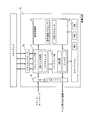
- the playback device includes a reading unit 1, a video decoder 2, a video plane 3, a subtitle decoder 4, a graphics plane 5, a combining unit 6, a transmitting / receiving unit 7, left and right shifting units 8a and 8b, a vertical shifting unit 9,
- the demultiplexing unit 10, the register set 11, the playlist information memory 12, the procedure execution unit 13, the reproduction control unit 14, the operation reception unit 15, and the OSD processing unit 16 are configured.
- Reading unit 1 The reading unit 1 reads an index table, a program file, a playlist information file, a stream information file, and a stream file from the recording medium.
- the reading unit 201 uses the extent start point information in the clip base information in the 3D stream information file and the extent start point information in the clip dependent information to perform stereoscopic interleaving.
- the stream file is divided into a main TS and a sub-TS and stored in separate read buffers.
- This division includes processing of extracting source packets from the stereoscopic interleaved stream file and adding them to the main TS by the number of packets of the source packet number indicated in the extent start point information in the clip dependent information, and clip base
- the processing is performed by repeating the process of extracting the source packet from the stereoscopic interleaved stream file and adding it to the sub TS for the number of packets of the source packet number indicated in the extent start point information in the information.
- the video decoder 2 includes a coded data buffer and a decoded data buffer, and pre-loads the view components constituting the dependent-view video stream into the coded data buffer, and then refreshes the decoder located at the head of the closed GOP in the base-view video stream.
- Decode the view component of the picture type (IDR type) intended for In this decoding all of the coded data buffer and the decoded data buffer are cleared. After decoding the IDR type view component in this way, the subsequent view component of the base view video stream that is compression-encoded based on the correlation with the view component and the view component of the dependent view video stream are decoded. . If uncompressed picture data for the view component is obtained by decoding, the picture data is stored in the decoded data buffer, and the picture data is used as a reference picture.
- motion compensation is performed for the subsequent view component of the base view video stream and the view component of the dependent view video stream. If uncompressed picture data is obtained for the subsequent view component of the base-view video stream and the view component of the dependent-view video stream by motion compensation, these are stored in the decoded data buffer and used as reference pictures.
- the above decoding is performed when the decoding start time indicated in the decoding time stamp of each access unit arrives.
- the video plane 3 includes a left-eye plane memory and a right-eye plane memory. Uncompressed picture data obtained by decoding the view component of the base view, and uncompressed picture data obtained by decoding the view component of the dependent view are the plane memory for the left eye and the plane for the right eye. Written to memory. This writing is performed when the playback start time indicated in the presentation time stamp of each access unit comes.
- the decoded picture data is written to either the left-eye plane memory or the right-eye plane memory depends on the base view indicator in the playlist information. If the base view indicator designates the base view video stream as "for left eye", the picture data that is the view component of the base view video stream is written to the plane memory for the left eye, and the view component of the dependent view video stream Is written in the plane memory for the right eye.
- the base view indicator specifies the base view video stream as “for right eye”
- the picture data that is the view component of the base view video stream is written to the plane memory for the right eye, and the view of the dependent view video stream is displayed.
- the picture data as a component is written into the plane memory for the left eye.
- These view components are sequentially output to the display device.
- the picture data of the left-eye plane memory and the picture data of the right-eye plane memory are simultaneously output in one frame period.
- the video plane for the left eye and the video plane for the right eye are composed of a plurality of line memories, and the pixel data constituting the video data is respectively stored in a 32-bit length storage element constituting the line memory.
- the coordinates on the screen of the pixel data constituting the picture data correspond to, for example, a combination of a ROW address that is an address of a line memory in a video plane and a COLUMN address that is a relative address of a storage element in the line memory.
- Subtitle decoder 4 decodes the PG_text subtitle stream, and writes the uncompressed bitmap and graphics obtained by the decoding to the graphics plane.
- the graphics plane 5 includes a PG plane 5a and a GFX plane 5b.
- the PG plane 5a stores subtitles obtained by decoding of the subtitle decoder 4.
- the GFX plane 5b stores the OSD drawn by the OSD processing unit 16.
- the PG plane 5a is composed of a plurality of line memories, and pixel data constituting uncompressed subtitles are respectively stored in halfword (8-bit) length storage elements constituting the line memory of the PG plane.
- the coordinates on the screen of the pixel data constituting the subtitle correspond to, for example, a combination of a ROW address indicating the line memory of the pixel data in the PG plane and a COLUMN address indicating the storage element in the line memory.
- the pixel data stored in the PG plane is an 8-bit pixel code.
- the 8-bit pixel code is converted into a Y value, a Cr value, a Cb value, and an ⁇ value by color conversion using a color lookup table.
- the PG plane when the resolution of picture data is set to 1920 ⁇ 1080, the PG plane stores pixel data of horizontal 1920 ⁇ vertical 1080.
- the memory element corresponding to the background part of the PG plane stores the Y value, Cr value, Cb value, and ⁇ value indicating the transparent color, and this part is combined with the left-eye video plane and the right-eye video plane. In some cases, the moving images in the left-eye video plane and the right-eye video plane can be seen through.
- the storage element corresponding to the foreground portion stores Y values other than the transparent color, Cr values, Cb values, ⁇ values, and Y values other than the transparent colors, Cr values, Cb values, ⁇ values, Subtitles will be drawn.
- the GFX plane 5b is composed of a plurality of line memories, and pixel data constituting the OSD is respectively stored in a double word (32 bits) length storage element constituting the line memory of the GFX plane.
- the coordinates on the screen of the pixel data constituting the OSD correspond to, for example, a set of a ROW address indicating the line memory of the pixel data in the GFX plane and a COLUMN address indicating the storage element in the line memory.
- Pixel data in the GFX plane is composed of an 8-bit R value, an 8-bit G value, an 8-bit R value, and an 8-bit transparency ⁇ .
- the GFX plane stores horizontal 1920 ⁇ vertical 1080 pixel data.
- the RFX, G value, B value, and ⁇ value indicating the transparent color are stored in the memory element that corresponds to the background part of the GFX plane, and this part is used for synthesis with the left-eye video plane and the right-eye video plane. , The moving images in the left-eye video plane and the right-eye video plane can be seen through.
- the storage element corresponding to the foreground part stores R values, G values, B values, ⁇ values other than the transparent color, and R values, G values, B values, ⁇ values other than the transparent colors, Subtitles will be drawn.
- the layer composition unit 6 performs layer composition in a plurality of plane memories.
- the plane memory that is the target of layer synthesis includes the left-eye video plane, right-eye video plane, PG plane, and GFX plane, and the left-eye video plane and right-eye video plane exist in the lower layers.
- the PG plane is present in the layer one above, and the GFX plane is present in the layer above it.
- the layer synthesizing unit 6 performs layer synthesis in accordance with this hierarchical structure, obtains a synthesized video in which subtitles and OSD are synthesized with each of the left-eye picture data and the right-eye picture data, and provides them for output.
- audio data in uncompressed / plaintext format is sent to other devices (including not only the display device but also amplifiers and speakers) connected to the playback device. Forward.
- devices such as a display device, an amplifier, and a speaker can receive uncompressed / plaintext picture data and uncompressed / plaintext audio data, and can realize reproduction output.
- the counterpart device has a decoding capability, it is possible to pass-through transmission of a video stream and an audio stream. In pass-through transmission, a video stream and an audio stream can be transmitted in a compressed / encrypted format.
- the left / right shift unit 8a realizes stereoscopic vision by giving a horizontal offset to the X coordinate of the pixel data in the PG plane.
- the coordinates on the screen of the pixel data constituting the subtitle correspond to a combination of the ROW address indicating the line memory of the pixel data in the PG plane and the COLUMN address indicating the storage element in the line memory. . If the COLUMN address indicating the storage element for each pixel data of subtitles in the PG plane is increased or decreased by an address corresponding to plane_offset_value of the offset sequence, the coordinates of the pixel data can be displaced in the left-right direction.
- the address shift of the pixel data can be realized by a copy process of the pixel data accompanied with the address adjustment.
- you want to change the X coordinate of the pixel data by the number of pixels X specified by the plane_offset_value of the offset sequence when copying the pixel data, specify the COLUMN address that indicates the storage element that is the copy destination as the number of pixels Adjust only the address corresponding to X before and after. If copying is performed on the assumption of such adjustment, the coordinates of the pixel data are shifted in the left-right direction.
- the layer synthesizing unit 6 performs layer synthesis, the pixel data is copied between the line memory constituting the PG plane and the line memory in the layer synthesizing unit 6. With proper address adjustment, the PG plane can be shifted left and right.
- the left / right shift unit 8b realizes stereoscopic vision by giving a horizontal offset to the X coordinate of the pixel data in the GFX plane.
- the coordinates on the screen of the pixel data constituting the OSD correspond to a combination of the ROW address indicating the line memory of the pixel data in the GFX plane and the COLUMN address indicating the storage element in the line memory. Therefore, the coordinates of the pixel data can be displaced in the left-right direction by increasing or decreasing the COLUMN address indicating the OSD pixel data storage element in the GFX plane by an address corresponding to plane_offset_value.
- the address shift of the pixel data can be realized by a copy process of the pixel data accompanied with the address adjustment.
- the COLUMN address that points to the storage element that is the copy destination corresponds to the number of pixels X Adjust only the address you want to move back and forth. If copying is performed on the assumption of such adjustment, the coordinates of the pixel data are shifted in the left-right direction.
- the layer synthesizing unit 6 performs layer synthesis, the pixel data is copied between the line memory constituting the GFX plane and the line memory in the layer synthesizing unit 6. If the address is adjusted properly, the GFX plane can be shifted left and right.
- the vertical shift unit 9 shifts pixel data in the video plane in the vertical direction, thereby providing a blank area at the upper end or the lower end of the video plane.
- the coordinates on the screen of the pixel data constituting the picture data correspond to a combination of the address of the line memory in the video plane and the COLUMN address indicating the storage element in the line memory. Therefore, if the ROW address indicating the line memory of pixel data in the video plane is shifted by addresses corresponding to top_down_offset and bottom_up_offset, the coordinates of the pixel data can be displaced in the vertical direction.
- the address shift of the pixel data can be realized by a copy process of the pixel data accompanied with the address adjustment.
- the ROW address indicates the line memory that is the copy destination on the Y line or below the Y line. Adjust to. If the pixel data copy is executed on the assumption of such adjustment, the ROW address indicating the line memory of the pixel data will be changed, and along with this change, the coordinates of the pixel data will be upward or downward. Will shift.
- the layer composition unit 6 performs layer composition, the pixel data is copied between the line memory constituting the video plane and the line memory in the layer composition unit 6. If the address is adjusted properly, the video plane can be shifted up and down.
- the demultiplexing unit 10 includes a source depacketizer that converts a source packet into a TS packet, a PID filter that performs packet filtering, and has a packet identifier described in a stream entry of a basic stream selection table of 3D playlist information.
- the source packet is converted to a TS packet and then output to the decoder.
- the source packet having the packet identifier described in the stream entry of the stereoscopic stream selection table of the 3D playlist information is converted to a TS packet and then the decoder Output to.
- Which packet identifier is used among the plurality of entries in the basic stream selection table and the plurality of entries in the extended stream selection table depends on the setting of the stream number register in the player status register.
- the register set 11 includes a plurality of player status registers and a plurality of player setting registers.
- Each player status register and player setting register is a register having a word length of 32 bits.
- Each register having a 32-bit length is given a register number, and a register to be accessed is specified by using this register number.
- each bit data that constitutes one word (32 bits) of each register is called b0 to b31.
- the most significant bit is called b31, and the least significant bit is called b0.
- the bit range from the bit position of the bx bit to the bit position of the by bit is expressed by the notation [bx: by].
- a 32-bit length bit string stored in the player setting register / player status register of a predetermined register number and having a value in an arbitrary bit range [bx: by] is the value of the operating system when the program operates. Treated as environment variables (system parameters or player variables).
- a program that performs playback control can acquire system parameters through system properties and an application programming interface (API). Unless otherwise prohibited, the program can rewrite the values of the player status register and player setting register. For an object-oriented programming language-based program, it is a requirement that legitimate authority is given to obtain and rewrite system parameters.
- the player status register is a hardware resource for storing the numerical value that is the operand when the MPU of the playback device performs an arithmetic operation or a bit operation, and the initial value is set when the optical disc is loaded.
- This is a register for determining the validity of the stored value when the state of the playback device changes, such as a change of the current play item.
- the stored value includes a current title number, a current playlist number, a current play item number, a current stream number, a current chapter number, and the like. Since the initial value is stored when the optical disk is loaded, the stored value is temporary. If the optical disk is ejected or the playback apparatus is turned off, the stored value loses its validity.
- the player setting register is different from the player status register in that power supply measures are taken. Since power supply measures are taken, the stored value is saved in a non-volatile memory when the playback device is turned off, and the stored value is restored when the playback device is powered on.
- the play list information memory 12 stores a plurality of play item information constituting the play list information and a combined stream obtained by combining the basic stream selection table and the extended stream selection table included in the play item information. Stores registered columns.
- Procedure execution unit 13 executes a stream selection procedure on the combined stream registration information of the basic stream selection table and the extended stream selection table, and writes the current subtitle stream number in the stream number register in the register set 11. Then, the optimum layout for the current subtitle stream is determined, and the vertical shift unit 9 is caused to shift the video plane corresponding to this layout.
- the subtitle layout includes a normal layout, an upper end arrangement layout, and a lower end arrangement layout. When the upper end arrangement layout is adopted as the layout of the current subtitle stream, the vertical shift unit 9 is controlled to shift the video plane downward. When the lower end layout is adopted as the layout of the current subtitle stream, the up / down shift unit 9 is controlled to shift the video plane upward.
- the playback control unit 14 executes random access from an arbitrary time point on the time axis of the video stream. Specifically, when playback from an arbitrary time point on the time axis of the video stream is ordered, an access unit corresponding to the arbitrary point of time using the basic entry map and the extended entry map in the 3D stream information file Search the source packet number of.
- the access unit includes a set of a view component of a base view video stream and a view component of a dependent view video stream, and a source packet storing an access unit delimiter for the access unit by the search. Source packet numbers are identified. Random access is performed by executing reading and decoding from the source packet number.
- the main TS, sub-time is used by using the in-time and out-time specified in the main path information of the 3D playlist information and the in-time and out-time specified in the sub-path information.
- Play list reproduction is started by executing random access to each TS.
- Operation acceptance unit 15 detects and notifies a user operation performed on an input device such as a remote controller or the front panel of the playback device 102. This notification is made by generating a UOP according to the interrupt generated by the interrupt handler in the device driver corresponding to these input devices.
- the UOP is an event (UOP event) that occurs when a key press is detected by a key matrix provided on the remote control or the front panel, and has an attribute corresponding to the pressed key. Specifically, when the interrupt handle of the device driver corresponding to the remote control or front panel detects a key press by key sense for the key matrix, an UOP event is generated by generating an interrupt signal based on the key press. Is done.
- OSD processing unit 16 When the playback control unit 14 executes a process according to the operation received by the operation receiving unit 15, the OSD processing unit 16 displays a built-in GUI corresponding to the operation and visually feeds back the operation by the user. Then, processing corresponding to the user operation is executed.
- OSD is used as an example of an embedded GUI.
- the process requested by the user operation is a setup process
- the OSD of the setup menu is displayed on the screen and a setting operation for the OSD is accepted.
- the player setting register in the register set 11 is updated. If it is playback or stop, the playback control unit 14 is caused to stop playback of the playlist or playback of the playlist in accordance with the user operation.
- FIG. 12 is a diagram showing the internal configuration of PSR2 and PSR22, in which components that require special explanation are extracted from the internal configurations and data structures shown so far, and the relationship between the components is drawn.
- the demultiplexing unit 10 and the caption decoder 4 are shown on the lower side.
- PSR2 and PSR22 which are 32-bit length registers in the register set 11 and a memory storing the extension stream selection table are depicted.
- Arrows Py1 and Py2 in the drawing schematically indicate reference to the PSR2 by the demultiplexing unit 10, the stream entry of the upper end subtitle, and the stream entry of the lower end subtitle in the stream registration information.
- Arrows Py3, Py4, and Py5 in the drawing schematically refer to the upper end arrangement presence / absence flag / lower end arrangement existence / non-existence flag reference by the subtitle decoder 4, the reference to the upshift / downshift status register, and the reference to the stereoscopic status register. Show.
- [B11: b0] of PSR2 constitutes the stream number register.
- the stream number register stores a value from 1 to 255 as a stream number. By storing 0XFFF, a subtitle non-selected state is indicated.
- [B0] of PSR22 constitutes the stereoscopic status register.
- the stereoscopic status register is set to 0 to indicate that it is in 2D playback mode. Setting it to 1 indicates that it is in 3D playback mode.
- [B2: b1] of PSR22 constitutes the upshift / downshift status register.
- the upshift / downshift status register indicates that there is no upshift or downshift capability by setting b2 and b1 to 0,0.
- Setting b2 and b1 to 1,0 indicates that the downshift capability of the video plane exists.
- FIG. 13A shows a normal layout. As shown in the figure, there is a top_margin height margin on the upper end side of the caption. There is a bottom_margin height margin on the bottom edge.
- the vertical width of the moving image is the size of Frame_Height- (top_margin + bottom_margin). In this case, Y0 and Y1 of OSD are secured in the lower end side margin.
- bottom_margin and top_margin are values obtained by doubling the offset described in the bottom_margin field and top_margin field of the in-plane activation information in the playlist information.
- FIG. 13B shows the upper end layout.
- a blank area of top_down_offset exists on the upper end side of the screen.
- Y0 and Y1 are secured in the margin area of the upper end side margin.
- top_down_offset is a value obtained by doubling the offset described in the top_down_offset field of the in-plane activation information in the playlist information.
- FIG. 13 (c) shows a bottom layout.
- a bottom_up_offset margin exists on the upper end side.
- the upper coordinate of the lower margin area is a coordinate obtained by adding bottom_up_offset to Frame_Height- (top_margin + bottom_margin) which is the vertical width of the moving image frame.
- the value of this bottom_up_offset is a value obtained by doubling the offset described in the bottom_up_offset field of the in-plane activation information in the playlist information.
- the lower end coordinate of the lower margin area is Frame_Height.
- Y0 and Y1 are the bottom margins. Therefore, Y0 becomes bottom_up_offset + Frame_Height- (top_margin + bottom_margin), and Y1 becomes Frame_Height.
- the aspect ratio of cinesco size (1: 2.35) is common, and when storing images on an optical disc such as a BD-ROM, the main image without changing the aspect ratio.
- FIG. 14 shows layer composition of the video plane contents shifted downward and the graphics plane.
- FIG. 14A shows a case where a shift is made to make the subtitle appear to the front
- FIG. 14B shows a case where a shift is made to make the subtitle appear behind.
- the back side is a video plane
- the front side is a graphics plane.
- the video plane has an upper end layout as shown in FIG. 14B by being shifted downward.
- (a) a plane shift for making the subtitles appear in front of the near-side graphics plane is performed, and an offset in the horizontal direction is created in the X coordinate of the pixel in the graphics plane. Is visible in the foreground.
- FIG. 15 shows layer composition of the video plane contents shifted upward and the graphics plane.
- the video plane has the layout shown in FIG. 13C, a blank area exists on the lower end side, and Y0 is set to bottom_up_offset + Frame_Height- (top_margin + bottom_margin).
- FIG. 15 (a) shows a case where a shift is made to show the subtitles in front
- FIG. 15 (b) shows a case where a shift is made to show the subtitles in the back.
- the back side is a video plane
- the front side is a graphics plane.
- the video plane has a lower end layout as shown in FIG. 13B by being shifted upward.
- a plane shift for making subtitles appear in front is performed on the near-side graphics plane, and an offset in the horizontal direction is created in the X coordinate of the pixel in the graphics plane.
- the graphics plane is visible in the foreground.
- FIG. 16A shows a stereoscopic image obtained by layer synthesis in FIG.
- FIG. 16B shows a stereoscopic video obtained by layer synthesis in FIG. This completes the description of layer composition with the video plane.
- FIG. 17 shows a temporal transition between the layout of the PG plane and the layout of the OSD.
- the first level shows a plurality of pictures and an OSD synthesized with each picture.
- the second level shows play item information # 1, # 2, # 3.
- the third level shows the description contents of the stream registration information in the extended stream selection table corresponding to each play item information.
- the layout of the PG plane is the upper end arrangement layout. Then, the OSD layout is selected as the upper end layout.
- the PG plane The layout of is a normal layout. Then, the OSD layout is selected as the normal layout.
- the PG plane This layout is the upper end layout. Then, the OSD layout is selected as the upper end layout.
- FIG. 18 shows a temporal transition between the layout of the PG plane and the layout of the OSD.
- the first level shows a plurality of pictures and an OSD synthesized with each picture.
- the second level shows play item information.
- the third level shows the description contents of the stream registration information in the extended stream selection table corresponding to each play item information.
- the layout of the PG plane is the lower end arrangement layout.
- the OSD layout is selected as the bottom layout.
- the PG plane The layout of is a normal layout. Then, the OSD layout is selected as the normal layout.
- the PG plane This layout is the bottom layout. Then, the OSD layout is selected as the bottom layout.
- Playlist playback control procedure The above-described subtitle stream selection and layout selection for subtitle display are performed in conjunction with play list reproduction. A description will be given of a playlist playback control procedure, which is a precondition for subtitle stream selection and subtitle layout selection.
- the above reproduction control can be realized by describing the processing procedure shown in the flowcharts of FIGS. 19 to 24 in an object-oriented compiler language and causing the computer to execute it.
- FIG. 19 shows a playlist playback procedure.
- This flowchart constitutes a loop in which the current play item number is set to 1 in step S1, and then the processing in steps S2 to S6 is repeated.
- the stream number is determined by Procedure when playback condition is changed (step S2), the stream file storing the ES corresponding to the stream number is opened, the source packet sequence is read (step S3), and read.
- the source packet sequence corresponding to the stream number is instructed to be demultiplexed (step S4), and the read source packet is output from the play item intime to the outtime, and from the subplayitem intime to the outtime.
- the process of instructing the decoder to play until time is repeated until the current play item number reaches the final number. If it is not the final number (No in step S6), the current play item number is incremented and the process proceeds to step S7.
- step S7 it is determined whether or not there is a stream selection request in step S7, and if there is a request, the requested stream number is set to x and Procedure when stream change is requested is executed (step S8). If it is the final number, the process ends (Yes in step S6).
- the PG_text subtitle stream referred to by the PG_text subtitle stream number of PSR2 is selected using the output mode (PSR22), the stereoscopic PG capability in PSR24, and is_SS_PG.
- FIG. 20 is a flowchart showing the processing procedure for the Procedure when playback condition is changed for the PGtestST stream.
- the processes in steps S11 to S22 are common processes in the stereoscopic mode and the planar view mode.
- Steps S23 to S24 are processing specific to the stereoscopic mode.
- step S11 the current PG_text subtitle stream number is acquired from PSR2, and in step S12, it is determined whether the current PG_text subtitle stream number is for the PG stream or the text subtitle stream.
- step S13 checks whether or not the PG stream corresponding to the current PG_text subtitle stream number satisfies the condition (A) and the condition (B).
- condition (A) and condition (B) are defined as follows.
- the playback device has the ability to decode the PG stream specified from the current PG_text subtitle stream number.
- step S14 it is checked whether or not the text subtitle stream corresponding to the current PG_text subtitle stream number satisfies the condition (A) and the condition (B).
- the playback device has the ability to expand the character code of the text subtitle stream of the current PG_text subtitle stream number into a bitmap. Such reproduction capability is indicated by PSR 30 in the register set 23.
- the playback device must have the ability to support the language characteristics of the text subtitle stream of the current PG_text subtitle stream number.
- the text subtitle stream of that language can be said to be “decoded”, and the character code in that language is expanded into a bitmap. Capabilities and support capabilities that support the characteristics of the language need to exist on the playback device side.
- the 30th player setting register (PSR30) of the playback device has a BIG5 character code, a CN-GB encoding method for GB2312, a GB18030-2000 character code, an EUC-KR encoding method for KSC5601-1987,
- PSR30 the 30th player setting register
- the playback device has the processing capability of expanding the text code into a bitmap. Therefore, whether or not the target text subtitle stream can be decoded corresponds to the text code type of the text subtitle stream out of the processing capabilities for each character code and encoding method indicated in PSR30. Judgment can be made by referring to.
- Japanese subtitles can be determined to support language characteristics only when the functions “horizontal writing”, “vertical writing”, “line ending prohibition”, and “ruby” are supported.
- Arabic subtitle display can be determined to support the language characteristics only when the functions of “drawing from right to left” and “ligatures / hugging” are supported.
- a text subtitle stream of a certain language can be developed into a bitmap and the characteristics of the language can be supported, it can be said that the above conditions (A) and (B) are satisfied. If the text subtitle stream of the language can be expanded into a bitmap, but the characteristics of the language cannot be supported, the condition (B) is not satisfied and only the condition (A) is satisfied be able to.
- the support capability for each language is set for each language in each bit of PSR48 to 61 in the register set. Specifically, in PSR48 to 61, there are flags corresponding to each of the 3-byte language codes defined in IS0639-2 / T. In these flags, text subtitles corresponding to each language code are present. The presence or absence of display capability is set.
- the 3-byte code “ita” indicates Italian
- the 3-byte code “jpn” indicates Japanese
- the 3-byte code “jav” indicates Javanese. Since the language codes defined in IS0639-2 / T cover 430 languages in this way by 3-byte codes, the text subtitle stream described in the stream number table can be decoded when determining the current PG_text subtitle stream. In determining whether or not, the flags in the PSRs 48 to 61 are referred to. In this way, it is possible to properly determine whether or not even a minority language can be decoded.
- step S15 the playback device determines whether or not the condition (Z) is satisfied.
- the condition (Z) means that the user intends to play back subtitles in an unsupported language that does not support language characteristics, and this intention is indicated in the PSR 30 in the register set.
- step S16 is executed. This is to determine whether or not the number of PG_text subtitle streams in the stream selection table of the current play item is zero. If there is no PG_text subtitle stream that is permitted to be played back in the stream selection table, the PG_text subtitle stream number in PSR2 is maintained (step S17).
- step S18 is executed. This is a step for asking the validity of the current PG_text subtitle stream number, is the current PG_text subtitle stream number less than or equal to the total number of stream_entry in the stream selection table, and satisfies the conditions (A) and (B)? Determine if.
- step S20 determines whether or not the current PG_text subtitle stream number is equal to or less than the total number of stream_entry in the stream selection table and satisfies the conditions (A) and (Z). If it is satisfied, the PG_text subtitle stream number of the text subtitle in the unsupported language is set in PSR2, but since the user intends to play back the unsupported language, PSR2 is not changed (step S21). If it is determined in step S20 that the condition is not satisfied, an optimum stream for the current play item is selected (step S22).
- step S23 the stream registration information of the PG_text subtitle stream of PSR22 and the current PG_text subtitle stream are acquired from the extension stream selection table. Thereafter, in step S24, the playback type of the current PG_text subtitle stream is determined.
- FIG. 21 is a flowchart showing a processing procedure for selecting an optimal PG_text subtitle stream for the current playitem.
- step S30 it is checked whether or not all the PG_text subtitle streams satisfy the conditions (a) to (c).
- conditions (a) to (c) are defined as follows.
- the playback device has the ability to decode PG stream i.
- PG_language_code of PG stream i matches the language setting in the playback device.
- the language setting in the playback apparatus is indicated by PSR17 in the register set.
- conditions (a) to (c) are defined as follows.
- the playback device must have the ability to expand the character code of the text subtitle stream i into a bitmap.
- the playback device has the ability to support the language attribute of the text subtitle stream i.
- step S31 it is determined whether or not the playback device satisfies the condition (Z) (: playback of unsupported language) described in the previous flowchart. If not, it is determined in step S32 whether there is a PG_text subtitle stream that satisfies the conditions (a) to (c). If there is a PG_text subtitle stream satisfying the conditions (a) to (c), select the stream entry whose corresponding stream entry is at the top in the stream selection table, and select the selected PG_text subtitle stream number. , PSR2 is set (step S33).
- step S34 If there is no PG_text subtitle stream satisfying the conditions (a) to (c), it is determined in step S34 whether there is a text subtitle stream that satisfies a more relaxed condition.
- the relaxed condition means that the conditions (a) and (b) are satisfied, and it is determined in step S34 whether there is a text subtitle stream that satisfies these conditions. If there is a PG_text subtitle stream satisfying the conditions (a) and (b), select the stream entry whose corresponding stream entry is at the top in the stream selection table and select the selected PG_text subtitle stream number. , PSR2 is set (step S36).
- step S35 the PG_text subtitle stream number of 0xFFF is set in PSR2 (step S35). If it is determined in step S31 that the condition (Z) is satisfied, it is determined in step S37 whether there is a PG_text subtitle stream that satisfies another relaxed condition. The other relaxed conditions satisfy the conditions (a) and (c). In step S37, it is determined whether there is a PG_text subtitle stream that satisfies these conditions.
- the PG_text subtitle stream number of the selected PG_text subtitle stream satisfying the condition (a) and the condition (c) is selected by selecting the stream stream corresponding to the first entry in the stream selection table. Is set to PSR2 (step S38).
- step S39 it is determined in step S39 whether there is a PG_text subtitle stream that satisfies the condition (a). If present, select the PG_text subtitle stream that satisfies the condition (a) whose corresponding stream entry is at the top in the stream selection table, and set the selected PG_text subtitle stream number to PSR2 (Step S40). If not, 0xFFF is set to PSR2 (step S35).
- FIG. 22 is a flowchart showing a procedure of “Procedure when stream change is requested” to be executed when a stream change is requested by the set stereoscopic stream command (SetstreamSSCommand).
- step S41 it is determined whether the number X designated by the operand in the set stereoscopic stream command means the stream number for the PG stream or the stream number for the text subtitle stream.
- step S42 checks whether or not the PG stream (PGx) corresponding to the number X satisfies the following conditions (A) and (B).
- the playback device must be capable of decoding the PG stream specified by number X.
- Step S43 checks whether or not the text subtitle stream (textSTx) corresponding to the number X satisfies the following condition (A) and condition (B).
- the playback device has the ability to expand the character code of the text subtitle stream X corresponding to the number X into a bitmap.
- the playback device must have the ability to support the language attribute of the text subtitle stream X corresponding to the number X.
- step S44 the playback device checks whether or not the condition (Z) is satisfied, and performs the determination in step S45. In this determination, it is determined whether or not the number is equal to or less than the total number of stream_entry in the stream selection table and the conditions (A) and (B) are satisfied. If it satisfies, the PG_text subtitle stream of the PG_text subtitle stream number corresponding to the number X is selected and set to PSR2 (step S46).
- step S45 If it is determined in step S45 that the condition is not satisfied, the determination in step S47 is executed. This determination is to determine whether the number is equal to or less than the total number of stream_entry in the stream selection table and satisfies the conditions (A) and (Z). If satisfied, the PG_text subtitle stream corresponding to the number X is selected, and the PG_text subtitle stream number is set to PSR2 (step S48).
- step S49 the determination in step S49 is performed. This determination is to determine whether the number X is 0xFFF. Otherwise, the PSR2 value is maintained assuming that there is no PG_text subtitle stream that is permitted to be played back in the stream selection table (step S50).
- an optimal PG_text subtitle stream is selected for the current play item (step S51).
- the selection of this optimal PG_text subtitle stream is the same as that shown in FIG.
- steps S52 to S55 are processing specific to the stereoscopic mode. Specifically, is_SS_PG of the PG stream X specified by the PG stream number X is acquired from the stream registration information in the extension stream selection table (step S23).
- FIG. 23 is a flowchart showing the processing procedure of Procedure when stream is requested to be executed when a stream change is requested by a set stream command or a user operation requesting a stream number change.
- step S56 the stream number designated by the operand of the set stream command or the stream number designated by the user operation requesting the stream number change is set to the number X, and then steps S41 to S50 are performed. , S23 and S24 are executed. Since the processing contents of steps S41 to S50, S23, and S24 are the same as those in FIG. 22, the same reference numerals are given and the description thereof is omitted.
- the playback type of the current subtitle stream is determined according to the caption display capability in the playback apparatus and the contents of the extended stream selection table for each play item information in the playlist information. There is a need.
- the flowchart of FIG. 24 shows the processing procedure for determining the playback type of the current subtitle stream as the subroutine of FIGS.
- FIG. 24 is a flowchart showing a processing procedure for determining the playback type of the current stream type.
- processing is performed in any of steps S65 to S67, steps S68 to S70, steps S72, S73, and step S71 according to the combination of the determination results in the determination steps of step S62, step S63, and step S64.
- the structure is branched.
- Step S62 is a determination as to whether or not the upper end arrangement presence / absence flag corresponding to the current subtitle stream number is set to ON, and “capability is present” is indicated in the lower shift capability flag of the video plane. If Step S62 is Yes, the playback type of the current subtitle is set to the playback type of the upper end layout in Step S65, and the video plane is shifted down by top_down_offset in Step S66.
- step S67 the plane shift using the offset sequence indicated by the upper end subtitle offset sequence ID reference information corresponding to the stream number of the current stream stored in PSR2 among the plurality of stream registration information in the extension stream selection table Is executed on the graphics plane. That is, the pixels of the PG plane and the GFX plane are shifted leftward or rightward by the number of pixels indicated by the offset_value of the offset sequence in the direction indicated by offset_direction of the offset sequence.
- Step S63 is a step executed on the assumption that Step S62 is No. That is, step S63 is a determination as to whether or not the lower end arrangement presence / absence flag corresponding to the current subtitle stream number is set to ON and the upper shift capability flag is present. If this step S63 is Yes, step S63 is performed.
- step S68 the playback type of the current subtitle is set to the playback type of the bottom layout
- step S69 the video plane is shifted upward by bottom_up_offset.
- step S70 the plane shift using the offset sequence indicated by the lower end subtitle offset sequence ID reference information corresponding to the stream number of the current stream stored in PSR2 among the plurality of stream registration information in the extension stream selection table Is executed on the graphics plane.
- Step S64 determines whether or not the stereoscopic presence / absence flag corresponding to the current subtitle stream number is set to ON and the b2 stereoscopic PG capability in PSR24 is “1”. If step S64 is Yes, the playback type of the current subtitle stream is set to stereoscopic PG using the left eye PG stream and right eye PG stream (step S71).
- the demultiplexing unit performs demultiplexing of the TS packet of the packet identifier corresponding to the stream number of the current stream stored in PSR2 but indicated by the packet identifier reference in the right eye stream entry and the left eye stream entry. Make it.
- Step S64 the playback type is set to 1 plane + Offset (Step S72).
- step S73 the plane using the offset sequence indicated by the PG_text subtitle offset sequence ID reference information corresponding to the stream number of the current stream stored in PSR2 among the plurality of stream registration information in the extension stream selection table Shift is performed on the graphics plane.
- step S67, step S70, and step S73 the horizontal shift unit 8 is caused to perform a horizontal shift based on the plane shift direction information and the plane offset value. It is optimal in each frame period of the GOP on the time axis.
- FIG. 25 (a) shows a display guidance for the title name, chapter name, and elapsed playback time.
- the title name is written as Tx
- the chapter name is written as Cx
- the playback elapsed time is written as XX: YY: ZZ.
- (B) shows the OSD for visual feedback to the user operation.
- the playback mark mk1, pause mark mk2, fast forward mark mk3, rewind mark mk4, and recording mark mk5 are all visually recognized when these operations are accepted by the playback device when the user performs the corresponding operations. It is a field.
- the prohibition mark mk6 is used to feed back the prohibition to the user when the user performs a prohibition of the operations as described above.
- the EG mark mk7 provides visual feedback that selection of English subtitles is requested.
- JP mark mk8 visually feeds back that selection of Japanese subtitles is requested.
- Figure (c) shows the menu OSD displayed when a menu call is made. It is composed of an audio button member, a caption button member, and a repeat playback button member, and the language type such as Japanese or English can be set for the audio button member.
- the language type such as Japanese or English can be set.
- the button member for repeat playback it is possible to specifically set whether repeat playback is performed in units of chapters or in units of titles.
- Such a menu OSD has no display time limit, and if a menu call is made by the user, the menu remains displayed unless the user closes the menu.
- FIG. 4D shows layer composition of the GFX plane storing the OSD, the PG plane storing the subtitles, and the video plane.
- the GFX plane storing the OSD is used for layer composition so that it is closest to the front.
- FIG. 26A is a diagram illustrating a software layer hierarchy in the OSD processing unit 16.
- the OSD processing unit 16 displays an OSD information database 18, displays a menu of the OSD in response to a menu call, accepts a user operation, processes the user operation, and stores the OSD information.
- the OSD display program 20 is configured to receive a search request, search the OSD information database, and display OSD information that matches the search request.
- FIG. 26B is a block diagram illustrating the internal configuration of the OSD processing unit 16 from a functional aspect, regarding various execution modules constituting the program as functional components.
- functional components of the OSD processing unit 16 will be described with reference to this block diagram.
- the OSD processing unit 16 is functionally composed of an OSD layout selection unit 21, an OSD depth adjustment unit 22, a special caption determination unit 23, a blank area detection unit 24, an OSD arrangement determination unit 25, and a reduction unit 26. Is done.
- OSD layout selection unit 21 When the top layout or the bottom layout is selected as the subtitle layout, the OSD layout selection unit 21 selects the same layout as the layout of the built-in GUI.
- whether the subtitle layout is the upper end layout, the lower end layout, or the normal layout is determined by whether or not the upper end arrangement presence / absence flag, the lower end arrangement existence / non-existence flag of the extension stream selection table, the upper end arrangement status flag in the PSR 22, This is done by referring to the status flag.
- the OSD depth adjustment unit 22 adjusts the depth of the device-embedded GUI when displaying the device-embedded GUI in the 1 plane + Offset mode.
- the adjustment by the OSD depth adjustment unit 22 is performed by using the horizontal offset and the shift direction when the PG stream and the text subtitle stream are reproduced in the 1 plane + Offset mode as the horizontal offset when displaying the built-in GUI in the 1 plane + Offset mode.
- the OSD depth adjustment unit 22 is an offset sequence defined for each frame period of each GOP of the base-view video stream and the dependent-view stream when displaying subtitles in the 1 plane + Offset mode.
- the shift direction (offset_direction) and the shift amount (offset_value) for each frame period when the built-in GUI is displayed in the 1 plane + Offset mode are determined.
- the left and right shift unit 8b is caused to perform a plane shift in the GFX plane with the shift direction and the shift amount thus determined. By doing so, the OSD in the GFX plane is reproduced three-dimensionally in the same direction and the same amount as the caption.
- the special subtitle determination unit 23 determines whether or not the current subtitle stream to be reproduced is a special subtitle having a larger number of characters than a normal subtitle. The determination by the special subtitle determination unit 23 is that two or more subtitle streams having the same language attribute whose priority is set to the second or lower in the stream selection table are subtitle streams for special subtitles. It is done by judging that it is.
- Margin area detection unit 24 When the current subtitle stream is a text subtitle stream in the top layout or the bottom layout, the blank area detection unit 24 detects a blank area of the subtitle area secured at the top or bottom of the screen.
- the arrangement of the subtitles in the subtitle area in the upper end layout or the lower end arrangement layout is any of the right side, the left side, and the center alignment. And based on
- the OSD placement determination unit 25 determines the placement of an OSD that is a GUI built in the device.
- the subtitle stream is a special subtitle
- the blank area is detected by the blank area detection unit 24. Therefore, the layout position of the built-in GUI is the blank area detected by the blank area detection unit 24.
- Reduction unit 26 reduces the device built-in GUI to be displayed in the caption area.
- OSD information information for defining these OSDs.
- the OSDs shown in FIG. 25 are all defined by OSD information having a common specific data structure as shown in FIG. This common data structure will be described.
- FIG. 27 (a) shows a common data structure of OSD information.
- the output position indicates the OSD arrangement coordinates (x, y) in the GFX plane.
- output size indicates the width and height in the GFX plane.
- minimum scalling size indicates the minimum OSD size when placing an OSD on the GFX plane.
- the output_duration indicates how long the OSD display continues on the time axis of the video stream.
- output_data is an image bitmap and text representing an OSD image.
- the various OSDs in FIG. 25 are defined by the common data structure in FIG. 27A, and a database is constructed in the playback device.
- Fig. 27 (b) shows the correspondence between the OSD database and the GFX plane.
- the database is constructed from OSD information defined by the common data structure as described above, and the OSD information in this database can be called by specifying a number.
- the OSD is displayed in the size indicated by the width and height of the OSD information. This completes the description of the OSD information for realizing the OSD and the database constructed in the playback device by this OSD information.
- FIG. 28 is a flowchart illustrating a processing procedure of processing according to a user operation.
- Step S71 is a step of waiting for the start of reproduction, and this loop is repeated when the reproduction apparatus is activated.
- the OSD of the reproduction mark is displayed for a certain period (step S72), and the process proceeds to the determination step sequence including the determination steps of step S73, step S74, and step S75.
- Step S73 determines whether fast forward / rewind / pause / audio / subtitle switching is requested
- Step S74 determines whether a title / chapter / time display display operation has been performed
- Step S75 indicates a stop operation. It is a determination whether or not.
- step S73 becomes Yes and the process proceeds to step S78.
- Step S78 is a determination of whether or not the designated operation is prohibited in the user operation mask table. If it is prohibited, the OSD display of the prohibition mark is performed in step S79, and then a loop of steps S73 to S75 is performed. Return to.
- OSD display of fast forward / rewind / pause / audio / subtitle switching is performed in step S80, and processing corresponding to UOP is performed in step S81.
- step S74 If it is determined Yes in step S74, the process proceeds to step S77.
- step S77 the title / chapter / time OSD display is performed, and the process returns to the loop of steps S73 to S75.
- FIG. 29 is a flowchart showing a processing procedure for OSD display.
- the OSD database is searched by identifying the OSD to be displayed to obtain OSD information, and the subtitle layout is determined in step S83.
- a blank area is detected from Y0 to Y1 of the current subtitle layout.
- the currently selected current PG_text subtitle stream is a normal subtitle or a special subtitle with a large number of characters. Determine if there is any.
- Special subtitles include subtitle for Deaf Hearing (SDH) and commentary for movie directors. In order to simplify the explanation, “special subtitles with many characters” are assumed to be SDH unless otherwise specified.
- step S87 the arrangement position and the arrangement method are selected for the OSD arrangement.
- step S85 the OSD information x, y, height, width, and the like from the (X0, Y0) to (X1, Y1) that can be OSD drawn. Set the magnification, size, and display time.
- step S89 the OSD having the designated ID is rendered on the GFX plane.
- FIGS. 13A to 13C There are three subtitle layouts shown in the normal layout, top end layout, and bottom end layout of FIGS. 13A to 13C, and it is determined which of these is set as the layout of the current subtitle stream. I have to.
- the processing procedure for determining the layout of the current subtitle stream is as shown in the flowchart of FIG.
- FIG. 30 is a flowchart showing a processing procedure for OSD layout selection.
- the substance of the OSD layout selection unit 21 shown in FIG. 26B is a subroutine in FIG.
- step S91 PSR22 is acquired, and the process proceeds to determinations in steps S92 and S93.
- Step S92 is a determination of the display state in PSR22. If 2D, the normal layout is set in step S94. If 3D, the determination in step S93 is performed.
- Step S93 is a subtitle layout determination. If b2-b1 of PSR22 indicating the shift capability of the video plane is 00, the normal layout is set in step S94. If b2-b1 of PSR22 is 11, the lower end layout is set in step S95. If b2-b1 of PSR22 is 10, the upper end layout is selected in step S96.
- each layout Y0 that is the upper Y coordinate and Y1 that is the lower Y coordinate of the caption area changes.
- FIG. 31 is a flowchart showing a margin area detection procedure.
- the processing procedure shown in this flowchart is a subroutine, and when the subroutine is called, one or more arguments are accepted and the processing shown in this flowchart is executed. return it.
- the first argument of this subroutine is the subtitle layout being played back
- the second argument is the basic size of the 3D video being played back
- the third argument is the subtitle type.
- the return value is margin information (area, position, subtitle type) that can be OSD drawn.
- Step S105 is a subtitle type determination. If the subtitle type is a text subtitle stream, the margin detection of the text subtitle stream is performed, and the margin coordinate is determined as X0 which is the X coordinate of the OSD arrangement (step S106). .
- step S106 is skipped.
- step S107 X1 is set as Frame_Width, and X0, Y0, X1, and Y1 are set as regions (x0, y0) to (x1, y1) where OSD can be arranged.
- the same subtitle layout is selected as the layout of the built-in GUI.
- Subtitles are arranged in the same display area, and only the built-in GUI is not arranged in a position overlapping with a moving image.
- the configuration of the decoder in the PG stream is 1 decoder + 1 plane when the 1 plane + offset method is adopted.
- a 2 decoder + 2 plane configuration is used.
- Both the left-eye PG stream and the right-eye PG stream include a plurality of display sets.
- a display set is a collection of functional segments that constitute one screen display.
- the functional segment is a processing unit that is stored in the payload of a PES packet of about 2 Kbytes and supplied to the decoder, and reproduction control is performed using DTS and PTS.
- Each display set includes multiple functional segments.
- the plurality of functional segments include the following.
- the object definition segment is a functional segment that defines a graphics object.
- the graphics definition segment defines a graphics object by using a code value and a run length of the code value.
- the palette definition segment includes palette data indicating the correspondence between each code value and luminance, red color difference / blue color difference.
- the correspondence between the code value, the luminance, and the color difference is set to the same content.
- Window definition segment is a functional segment that defines a rectangular frame called a window in a plane memory for expanding an uncompressed graphics object on the screen. Drawing of graphics objects is restricted inside the plane memory, and drawing of graphics objects is not possible outside this window.
- the playback device Since a part of the plane memory is designated as a window for displaying graphics, the playback device does not need to draw graphics for the entire plane. Graphics only need to be drawn for a window of a limited size. Since it is possible to omit drawing of the display plane other than the window, the burden on the software on the playback device side is much lighter.
- the screen configuration segment is a functional segment that defines the screen configuration using the graphics object, and includes a plurality of control items for the composition controller in the graphics decoder.
- the screen configuration segment is a functional segment that defines the details of the display set in the graphics stream and also defines the screen configuration using the graphics object.
- Such screen configurations include Cut-In / Out, Fade-In / Out, Color Change, Scroll, and Wipe-In / Out.
- End segment This is a functional segment located at the end of a plurality of functional segments belonging to one display set.
- the playback device interprets the screen segment to the end segment as a functional segment constituting one display set.
- the start point of the display set is specified by the DTS of the PES packet storing the screen composition segment
- the end point of the display set is specified by the PTS of the PES packet storing the screen composition segment.
- the graphics stream for the left eye and the graphics stream for the right eye are packetized elementary streams (PES), the screen configuration segment is stored in the PES packet, and the PTS of the PES packet storing the screen configuration segment is the screen configuration segment. Indicates when to perform display by the display set to which it belongs.
- PES packetized elementary streams
- the PTS value of the PES packet storing the screen composition segment is the same for the left-eye video stream and the right-eye video stream.
- the PG decoder stores a “coded data buffer” that stores a functional segment read from a PG stream, a “stream graphics processor” that obtains a graphics object by decoding a screen configuration segment, and stores a graphics object obtained by decoding.
- Object buffer "Composition buffer” for storing screen composition segments, and screen composition segments stored in the composition buffer were decoded and obtained in the object buffer based on the control items in these screen composition segments
- a “composition controller” that configures a screen on the graphics plane using a graphics object.
- a transport buffer for adjusting the input speed of TS packets that make up the functional segment exists in the previous stage of the graphics plane.
- a CLUT unit that converts the pixel code that configures the graphics object stored in the graphics plane into luminance and color differences based on the graphics plane and the palette definition segment, and a shift unit for plane shift And exist.
- the pipeline in the PG stream is a graphics object obtained by decoding the object definition segment belonging to the display set that is a graphics decoder and writing the graphics object to the object buffer, and decoding the object definition segment belonging to the preceding display set. Is performed simultaneously with the process of writing the data from the object buffer to the plain memory.
- FIG. 32 shows the internal structure of the PG decoder.
- FIG. 5A shows a decoder model for displaying in the 1 plane + offset mode method.
- FIG. 5B shows a decoder model for displaying stereoscopic mode data.
- the part corresponding to the main body of the PG decoder is surrounded by a black frame, and the part corresponding to the latter stage of the PG decoder is surrounded by a one-dot chain line.
- the PG decoder has a single decoder configuration
- the graphics plane also has a single plane configuration.
- the graphics plane output is divided into left eye and right eye outputs, and a shift unit is added to each left eye output and right eye output.
- FIG. 5B there are two sets of transport buffer, PG decoder, graphics plane, and CLUT section, and the left-eye stream and the right-eye stream can be processed independently.
- the PG decoder Since the offset sequence is included in the video stream for the right eye, in the plain offset format, the PG decoder has a single decoder configuration, and the output of this one PG decoder is switched between the left eye and the right eye.
- the text subtitle stream is composed of a plurality of subtitle description data.
- the text subtitle decoder stores the “subtitle processor” that separates the text code and the control information from the subtitle description data, the “management information buffer” that stores the text code separated from the subtitle description data, and the control information.
- “Control information buffer” “Text render” that expands the text code in the management information buffer to bitmap using font data
- "Object buffer” that stores the bitmap obtained by expansion
- caption description A “drawing control unit” that executes control of text subtitle reproduction along the time axis using control information separated from the data.
- the “font preload buffer” that preloads font data
- the “transport stream (TS) buffer” that adjusts the input speed of TS packets that make up the text subtitle stream
- play item playback There is a “subtitle preload buffer” for preloading a text subtitle stream.
- the text subtitle decoder is followed by a “graphic plane” and a “CLUT part” that converts the pixel codes that make up the graphics object stored in the graphics plane into luminance and color differences based on the palette definition segment.
- FIG. 33 shows the internal structure of the text subtitle decoder.
- FIG. 4A shows a decoder model of the text subtitle decoder in the 1 plane + Offset mode
- FIG. 4B shows a decoder model of the text subtitle decoder in the stereoscopic mode.
- the portion corresponding to the text subtitle decoder main body is surrounded by a black frame
- the portion corresponding to the subsequent stage of the text subtitle decoder is surrounded by an alternate long and short dash line.
- a portion corresponding to the preceding stage of the text subtitle decoder is surrounded by a broken line frame.
- the graphics plane output is divided into left eye and right eye outputs, and a shift unit is added to each left eye output and right eye output.
- FIG. 5B there are a left-eye graphics plane and a right-eye graphics plane, and a bitmap developed by the text subtitle decoder is written to each of these graphics planes.
- the text subtitle stream Unlike the PG stream, the text subtitle stream generates subtitles by rendering engine by sending font data and character codes instead of sending graphics data as a bitmap. Therefore, stereoscopic viewing of subtitles is realized by 1plane + Offset mode. To do.
- FIG. 34 shows an internal configuration for synthesizing the outputs of these decoder models and outputting them by the 1 plane + Offset mode method.
- the layer model of the left-eye video plane, right-eye video plane, PG plane, and IG plane is enclosed by a black frame, and the portion corresponding to the subsequent stage of the plane memory is enclosed by a dashed line.
- the playback device In the 1 plane + Offset mode method, video planes for the left eye and for the right eye are prepared.
- the PG plane and IG plane are not separated for the left eye and the right eye, and there is only one common plane memory for the left eye and the right eye.
- the layer synthesis as described above is performed for each of the left-eye output and the right-eye output. Since the playback device needs to support both the BD presentation mode and the 1 plane + offset mode, the playback device basically has a hardware configuration of 2 decoders + 2 planes, 1 plane + offset mode, plane When the playback device is switched to the viewing mode, one of the combinations of 1 decoder and 1 plane is invalidated to have a 1 decoder + 1 plane configuration.
- an appropriate subtitle decoder configuration can be employed in each of the stereoscopic mode and the 1 plane + offset mode.
- the subtitle arrangement area is determined to be optimal. In the present embodiment, details of how to determine the OSD arrangement area when the text subtitle stream is the current subtitle stream will be described.
- FIG. 35 is a flowchart of SDH detection, which is a special subtitle.
- the processing procedure shown in this flowchart is a subroutine, receives one or more arguments, performs processing, and returns a return value.
- the first argument in this subroutine is a stream number register storing the stream number of the subtitle stream being reproduced, and the second argument is a basic stream selection table.
- the return value is a determination result of whether or not the selected current subtitle stream is SDH.
- the entry order in the stream selection table is set low, and such a subtitle stream having a low entry order is selected as the current subtitle stream. It is considered that the SDH subtitle stream is selected through the stream selection command and the stream selection API.
- the subtitle number being played is large with the same language attribute, it is determined as SDH and the loop is exited. Then, it is determined that the subtitle stream x is an SDH subtitle stream, and the processing is terminated assuming that the SDH subtitle stream is being reproduced. If the language attributes are different, the steps S117 to S119 are skipped, and the subtitle stream of the next number is determined.
- the simple OSD arrangement determination should be selected depending on whether or not the text subtitle stream as described above is SDH and the size of the area that can be used for OSD display.
- the flowchart of FIG. 36 shows the procedure for determining the optimal OSD arrangement.
- the substance of the OSD arrangement determining unit 25 shown in FIG. 26B is a subroutine in FIG.
- FIG. 36 is a flowchart of OSD placement determination.
- the processing procedure shown in this flowchart is a subroutine, and when the subroutine is called, one or more arguments are accepted and the processing shown in this flowchart is executed. return it.
- the first argument is a blank area where OSD drawing is possible
- the second argument is a result of determination as to whether or not SDH is being reproduced
- the third argument is OSD information about the OSD to be displayed.
- the return value is information related to the OSD to be displayed, and includes the display position, size, display time, and reduction ratio, which are OSD information adjusted by the margin area and the SDH display area.
- Step S121 is confirmation of the OSD display time. Thereafter, the processing of steps S127 to S130 is selectively executed according to the combination of the determination results of steps S122 to S126.
- Step S122 is a determination of display time setting
- step S123 is a determination of whether or not SDH playback is in progress.
- Step S124 is a subtitle type determination
- step S125 is a determination of whether or not the OSD size is equal to or smaller than the margin area size.
- Step S126 is a determination of whether OSD size ⁇ limit reduction rate is equal to or less than the margin area size.
- Step S122 If Step S122 is Yes, the OSD display time is infinite and does not disappear immediately, so the standard display position is selected in Step S127.
- step S123 becomes No and the process proceeds to step S129.
- a display position is selected from the margin area notified in step S129. If it is finite time but SDH, the determination in step S125 is made.
- Step S125 is a determination of whether or not the OSD size is equal to or smaller than the margin area. If the OSD size is equal to or smaller than the margin area, step S125 is Yes, and the OSD display position is selected from the margin area notified in step S129.
- Step S126 determines whether or not the size obtained by multiplying the OSD size by the limit reduction rate is equal to or smaller than the margin area size. If the size obtained by multiplying the OSD size by the limit reduction ratio is equal to or smaller than the margin area size, step S126 becomes Yes and the process proceeds to step S128. After calculating the OSD optimum reduction ratio in step S128, the OSD display position is selected from the blank area notified in step S129.
- step S124 If it is determined in step S124 that the current subtitle is PG, a region other than the blank area selected in step S130 is selected.
- Step S126 When the size obtained by multiplying the OSD size by the limit reduction rate exceeds the margin area size, Step S126 becomes No, so that the area other than the margin area selected in Step S130 is selected. This completes the description of the OSD placement determination processing procedure. Next, details of the OSD arrangement position determination procedure will be described.
- a text subtitle stream can define a plurality of subtitle areas on one screen, and the right end coordinates of these subtitle areas are different for each subtitle area. Therefore, when OSD is arranged on the screen, the margin for OSD arrangement must be determined based on the text subtitle existing on the rightmost side of the graphics plane.
- Detecting a blank area in a caption area is based on the assumption that area information defining a plurality of caption areas in the graphics plane exists. As a premise for detecting the blank area in the caption area, how the caption arrangement area in the text caption stream is defined will be described.
- FIG. 37A shows the syntax of area format information for defining a plurality of area information in a text subtitle stream.
- Character_vertivcal_position character_width that is the width of the text string, character_height that is the width of the text string, Character_flow that regulates the flow control of the text string, character_horizontal_verification that indicates how to adjust the horizontal position of the text string, text characters
- the data structure that uses character_vertivcal_verification that specifies how to adjust the vertical position of the column as a member variable has a structure that repeats a predetermined number (number_of_area_format), and this repeating structure allows a predetermined number ( number_of_area_format) is not composed of the member variables in FIG. So that the instance area format information is generated.
- the area information includes area_horizontal_position that is the horizontal start position of the area, are_vertivcal_position that is the vertical start position of the area, area_width that is the horizontal width, and area_height that is the vertical width.
- How the text string is arranged in the area is defined by character_horizontal_verification in the area information. And the right end coordinate of the area
- region is determined by how a text character string is arrange
- FIGS. 37B to 37D show how the right end coordinates of the area occupied by the text character string are determined by each of the plurality of areas in the graphics plane.
- the entire frame represents a graphics plane, and the frame inside the entire frame is a region.
- FIG. 37 (b) shows the right end coordinates (Lx, Ly) of the text string in the left-aligned arrangement.
- Lx is area_horizontal_position + character_width
- Ly is the same as are_vertivcal_position.
- FIG. 37 (c) shows the right end coordinates (Rx, Ry) of the text string in the right-aligned arrangement.
- Rx is area_horizontal_position + area_width
- Ry is are_vertivcal_position.
- FIG. 37 (d) shows the right end coordinates (Cx, Cy) of the text string string when centered.
- Cx is area_horizontal_position + area_width ⁇ (area_width ⁇ character_width) / 2, and Cy is are_vertivcal_position.
- the right end coordinates of the occupied area of the text string in each area in the graphics plane are detected, the right end coordinates can be used as a reference for the blank area. If the syntax of the region information of the text subtitle stream as described above is used, a program that executes the processing procedure of the flowchart of FIG. 38 is written and executed by the CPU, thereby causing the playback device to perform blank region detection. be able to. This completes the description of the area definition by the text subtitle stream. Next, details of the margin area detection procedure of the text subtitle stream will be described.
- FIG. 38 is a flowchart of blank area detection in a text subtitle stream.
- the processing procedure shown in this flowchart is a subroutine, and when the subroutine is called, one or more arguments are accepted and the processing shown in this flowchart is executed. return it.
- This argument becomes each of a plurality of subtitle display areas secured in the graphics plane for reproduction of the text subtitle stream.
- the return value is the X coordinate of the rightmost text subtitle in the plurality of subtitle display areas.
- Step S131 is confirmation of the number of areas, and then the process proceeds to a loop of step S132 to step S133.
- each of a plurality of caption display areas existing in the graphics plane is selected as a processing target, and the right end coordinate X0 of the caption display area to be processed is detected by the procedure of steps S134 to S138, and thus calculated.
- step S140 it is determined whether or not the subtitle display area X0 is larger than the maximum value of the right end coordinates of the subtitle display area calculated so far, and if so, the maximum value of the right end coordinates of the area is updated (step S140). The process of S141) is repeated.
- Step S134 is a confirmation of the subtitle arrangement method. If the subtitle arrangement is left justified, step S136 is executed. If the subtitle arrangement is centered, step S137 is executed. When the subtitle is left-justified, area_horizontal_position + character_horizontal_position + character_width is set to X0 in step S136.
- area_horizontal_position + area_width ⁇ (area_width ⁇ character_width) / 2 is set to X0 in step S137.
- area_horizontal_position + area_width is set to X0 in step S138.
- FIG. 39A shows a case where the OSD is arranged at the top of the screen in the standard state.
- This standard state is a state in which black bands exist above and below.
- (B) is a case where the video plane is shifted down and normal subtitles are displayed. In this case, subtitles and OSD interfere. At this time, since the same layout as the normal subtitle is selected as the OSD layout, the OSD is displayed in the subtitle area, and the subtitle depth is reflected in the OSD. *
- FIG. 39 (c) shows a case where the video plane is downshifted, the subtitles are SDH text subtitles, and the OSD is arranged in the video display area. Thereby, the interference between the OSD and the caption can be avoided.
- FIG. 39 (d) shows a case where the video plane is shifted downward, the subtitle is an SDH text subtitle, and the OSD is displayed in a reduced size.
- the OSD is reduced, and the OSD is arranged in the margin of the SDH subtitle area. As a result, the OSD is reduced and displayed in the subtitle area while reflecting the subtitle depth.
- FIG. 40 (a) it is assumed that the video plane is downshifted and the subtitles are SDH text subtitles. In this case, subtitles and OSD interfere. Also, there is no margin to display in a reduced size. Therefore, the display in the video area is selected while avoiding the SDH text subtitle area. As a result, the OSD is displayed in the video area while reflecting the subtitle depth.
- (B) shows a case where an OSD with no display timeout is displayed.
- 3D video and OSD interfere for a long time.
- the standard display position is selected.
- the setting OSD is arranged in the video area and the caption area.
- SDH and commentary subtitles are displayed by analyzing the area format information and area information in the text subtitle stream at the preload time. It is possible to suitably detect a blank area when the operation is performed.
- the area format information is extracted from the text subtitle stream that is scheduled to be preloaded to the subtitle decoder at the time of decoding, and analyzed, thereby appropriately analyzing the margin area of the subtitle. be able to. Also, whether a text subtitle stream is SDH or commentary subtitle is determined by referring to the priority order given to the target text subtitle stream in the stream selection table. Therefore, it is possible to narrow down the target of margin area analysis to a part of the subtitle stream. Therefore, the text subtitle stream analysis for detecting the blank area is not excessively performed, so that the reproduction of the text subtitle is not greatly delayed.
- the playback control unit of the playback device described in the above embodiments can be configured as a so-called BD-J platform.
- the OSD display application can be implemented as a system application that operates on the BD-J platform.
- the BD-J platform is a bytecode interpreter that converts bytecode into native code, a classloader for class loading, an application manager for application signaling, a HAVi device, and a playlist playback using the Java media framework.
- Software similar to the software group in the playback home engine (DVB-MHP) such as playback control engine, cache manager for cash-in / cache-out management, event manager for event processing A group becomes an action subject.
- APIs that can be used to realize stereoscopic playback on the BD-J platform include Java2Micro_Edition (J2ME) Personal Basis Profile (PBP 1.0), There is Globally Executable MHP specification (GEM1.0.2) for package media targets.
- J2ME Java2Micro_Edition
- PBP 1.0 Personal Basis Profile
- GEM1.0.2 Globally Executable MHP specification
- java.net for network processing
- java.awt for GUI processing
- java.lang for language processing
- java.io for I / O processing for recording media
- utilities The structured programming using methods, constructors, interfaces, and events of classes such as java.util and javax.media for the media framework makes it possible to describe processing related to OSD display.
- BD-J extension By using the extension API (called BD-J extension) for the BD-J platform, the data structure for stereoscopic playback described in the previous embodiments and the control using playback units in stereoscopic playback can be performed.
- This BD-J extension includes in-lid methods from methods in the java.net, java.awt, java.lang, java.io, java.util, and javax.media classes. Since it is a super interface, it is an extension of programming techniques using the java.net, java.awt, java.lang, java.io, java.util, javax.media classes, and an OSD display application that assumes stereoscopic playback Can be created.
- the extension API in the BD-J platform includes a setting acquisition class that commands state setting and state acquisition of the stereoscopic status register and the upshift / downshift status register in the register set.
- the setting acquisition class includes a constant field indicating the holding value of the stereoscopic status register and the upshift / downshift status register, an acquisition method for instructing acquisition of the holding value of the PSR, a holding value of the player setting register and the player status register. It consists of a setting method that commands setting.
- the method of the setting acquisition class includes the inlaid method of the method of the java.lang.object class. If the argument at the time of the method call is invalid, the java.lang.IlleghalArgumentException event that is an event of the java.lang class is thrown. Since this class inherits the methods and events of java.lang.object, the programmer uses the retained values of the stereoscopic status register and the upshift / downshift status register as an extension of java.lang.object. Program can be created.
- 3D content has been recorded on a recording medium and read for playback, but in this embodiment, the 3D content is “3D digital broadcast content” and is broadcast in the digital broadcast system. It is assumed that the playback device is supplied to the playback device.
- FIG. 41 shows the internal structure of a transport stream for supplying 3D digital broadcast content to a playback device.
- the first tier shows a plurality of TS packets that make up the transport stream.
- this transport stream there is a TS packet storing PAT at the head, followed by a TS packet storing PMT, and then a TS packet storing PCR. After this, there are multi-stream TS packet groups.
- PAT Program Association Table
- PMT Program Map Table
- PMT Program Map Table
- PCR Program Clock Reference
- the multi-stream packet group is a multiplex of TS packets that store a video stream, an audio stream, a TS packet constituting a subtitle stream, a subtitle information table, and an in-plane activation information table.
- the second row shows the video stream
- the third row shows the audio stream
- the fourth row shows the subtitle stream.
- the video stream in the second stage is composed of a plurality of picture data, but each picture data is in a side-by-side format.
- the side-by-side picture data is a multi-viewpoint image obtained by combining a left-eye image and a right-eye image in the horizontal direction.
- the subtitle stream in the fourth tier provides run length encoded graphics subtitles to the playback device.
- the subtitle information table in the fifth row provides details about the subtitle stream to the playback device.
- the in-plane validation information table at the fifth level instructs the playback device which part of the internal area of the video plane is to be validated.
- FIG. 42 (a) shows the internal structure of the subtitle stream.
- the subtitle stream is composed of a plurality of types of functional segments such as Page Composition Segment (PCS), Region Composition Segment (RCS), Pallet Define Segment (PDS), and Object DefineegSegmentt (ODS).
- PCS Page Composition Segment
- RCS Region Composition Segment
- PDS Pallet Define Segment
- ODS Object DefineegSegmentt
- the subtitle stream will be described.
- the epoch in this 3D digital broadcast content passes a complete description of the decoder's memory usage at its starting point.
- the epoch boundary provides a guaranteed service acquisition point.
- the epoch boundary signaling is done by the construction of the “mode change” page described by a segment.
- FIG. 42 (b) shows the relationship between the PCS, RCS, and caption information table.
- the left side of the figure shows the internal configuration of the PCS, and the middle shows the internal configuration of the RCS.
- the right side shows the internal structure of the caption information table.
- Page Composition Segment is composed of sync_byte, segment_type, page_id, segment_length, page_time_out, page_version_number, region_id, region_horizontal_address, region_vertical_address.
- Region Composition Segments consists of sync_byte, segment_type, page_id, region_id, region_version_number, region_fill_flag, region_width, region_height, region_depth.clut_id, pixel_code, object_id, object_type, pbject_provider_flag, object_horizontal_position, object_vertical_code, background_pixel Transmit the region list of.
- the region list defines a set of regions to be displayed at the time associated by the PTS.
- the RCS in the “mode change” or “acquisition point” display set following the full description of Region Composition Segments (RCS), introduces regions and allocates memory for them.
- the display set that results in the page update includes only the areas where the content is changed. This completes the explanation of PCS and RCS. Next, details of the caption information table will be described.
- the subtitle information table is composed of “upper end placement presence / absence flag”, “lower end placement presence / absence flag”, “region_vertical_address”, and “region_height”. Of these, region_vertical_address is the same as that described in the PCS, and region_height is the same as that described in the RCS. Arrows cf1 and cf2 in the figure indicate the identity between “region_vertical_address” and “region_height” in the caption information table, “region_vertical_address” in PCS, and “region_height” in RCS.
- the playback device can determine whether the caption is placed at the upper end or the lower end without analyzing the inside of the PCS and RCS. It is possible to know how much the position and size of the arrangement area is.
- FIG. 42 (c) shows the internal structure of the in-plane validation information table. As shown in this figure, the same information elements as in FIG. 10B are defined as the in-plane validation information table, so that the top end arrangement and bottom end arrangement of subtitles as described in the first embodiment are possible. become.
- FIG. 43 is a functional block diagram showing the configuration of the playback device according to the fifth embodiment. This figure is drawn based on the internal configuration diagram of FIG. 11 in the first embodiment. Compared with the internal configuration diagram as the base, the reading unit 1 is connected to the service receiving unit 101 and the receiving unit 102.
- the demultiplexing unit 10 is replaced with the demultiplexing unit 103, the video decoder 2 is replaced with the video decoder 104, the graphics plane 5 is replaced with the caption line memory 105, the GFX plane is replaced with the OSD line memory 106, The difference is that the caption decoder 4 is replaced with a caption decoder 107.
- new components service reception unit 101, reception unit 102, demultiplexing unit 103, video decoder 104, subtitle line memory 105, OSD line memory 106, subtitle decoder 107) in this embodiment will be described.
- the service reception unit 101 manages service selection. Specifically, a service change request based on a user instruction from a remote control signal or an instruction from an application is received and notified to the receiving unit 102.
- the receiving unit 102 receives a signal at the frequency of the TS carrier wave to which the selected service is distributed from an antenna or cable and demodulates the signal. Then, the demodulated TS is transmitted to the demultiplexing unit 103.
- the demultiplexing unit 103 When the demultiplexing unit 103 receives the transport stream sent from the receiving unit 102, the video / audio data multiplexed in the transport stream, the subtitle stream, the object carousel, the subtitle information table, the in-plane Separated from the activation information table.
- the video decoder 104 decodes side-by-side picture data constituting a video stream of 3D digital broadcast content, and writes a set of uncompressed left-eye image and right-eye image to the left-eye video plane 3a and right-eye video plane 3b.
- the subtitle line memory 105 is composed of a plurality of line memories. Each line memory stores pixel data constituting a line of subtitles.
- the OSD line memory 106 includes a plurality of line memories. Each line memory stores pixel data constituting an OSD for one row.
- the subtitle decoder 107 includes two buffer memories, a coded data buffer and a pixel buffer, and decodes a subtitle stream in the 3D digital broadcast content.
- the code data buffer stores the object definition segment in an encoded state.
- the pixel buffer stores a graphics object obtained by decoding the object definition segment.
- the subtitle decoder 107 performs transfer from the pixel buffer to the line memory in accordance with PCS.
- transfer from the pixel buffer to the line memory will be described.
- a list of Regions is defined in the pixel buffer.
- Region is a region defined on a buffer (Pixel Buffer) in which graphics obtained by subtitle decoding processing (Subtitle Processing) is stored in a subtitle decoder model.
- Region1 containing the subtitle “Shall We?” And Region2 containing the subtitle “Said the fly on the mirror” are defined in Pixel Buffer, and the identifier of Region1 is described in the PCS.
- uncompressed graphics constituting the subtitle “Shall We?” Are transferred from the pixel buffer to a buffer (Display) for synthesis with a moving image.
- “Shall We?” Is displayed.
- the identifier of Region 2 is described in the PCS, uncompressed graphics are transferred from the pixel buffer to the video plane. Then, the caption “Said the fly on the mirror” is displayed based on the description of the identifier.
- a buffer memory such as a coded data buffer and a pixel buffer is provided in the decoder, and the Region in this pixel buffer is transferred to a buffer for synthesis with a moving image (line memory for "Display"). Subtitles are displayed.
- the OSD processing unit 16 determines the caption layout in the 3D digital broadcast content
- the Region that is the display area on the upper end side of the picture data and the Region that is the display area on the lower end side are By being defined, the upper end arrangement and the lower end arrangement of subtitles as shown in FIGS. 13A and 13C are made.
- the PCS of the subtitle stream has a field called region_vertical_address, and the region_vertical_address field defines the upper left coordinate in the Region.
- the RCS has fields of region_width and region_height, and the region_height field defines the vertical width of the region.
- information (upper end arrangement presence / absence flag, lower end arrangement presence / absence flag) indicating whether the caption is arranged on the upper end side or the lower end side, and the upper end region or the lower end region are displayed.
- the region_vertical_address indicating the upper left coordinate and the region_height indicating the vertical width of the upper end region or the lower end region are described as separate caption information tables, and the OSD processing unit 16 performs caption layout according to the caption information table. Make a decision. Then, in the RCS that defines the upper end display area and the lower end display area of the picture data, the subtitle area is calculated using information indicating the upper left coordinates and the vertical width of the Region.
- region_vertical_address indicating the upper left coordinate of the lower end region is set as the upper left coordinate Y0 of the subtitle area on the lower end side.
- region_vertical_address indicating the upper left coordinate of the upper end region is set to the upper left coordinate Y0 of the caption region on the upper end side.
- region_vertical_address indicating the upper left coordinate of the Region is set to the upper left coordinate Y0 of the caption area on the lower end side.
- the OSD processing unit 16 adopts the same layout as the subtitle layout as the OSD display layout. Further, when the in-plane validation information table is transmitted in the digital broadcast 3D content, the coordinates of the arrangement area at the time of the upper end arrangement and the lower end arrangement of the subtitles may be acquired in the same procedure as in the first embodiment. .
- the playback device plays back 3D digital broadcast content
- the subtitle layout changes to the top layout and the bottom layout
- the same layout as the subtitle layout is used. Since it is selected as the layout of the built-in GUI, the built-in GUI and subtitles will be placed in the same display area, and only the built-in GUI will not be placed in a position that overlaps the video. .
- the present embodiment is an improvement in which an elementary stream to be stored in a BD-ROM is transmitted as a transport stream of 3D digital broadcast content, and a directory structure and a file structure of the BD-ROM are transmitted in an object carousel. .
- FIG. 44 is a diagram showing a directory structure and a file structure when a BD-ROM is selected as the recording medium in the first embodiment.
- a BDMV directory exists under a root directory, and a file (index.bdmv) storing an index table exists in the BDMV directory.
- Under the BDMV directory are an object directory (BDJO directory in the figure), playlist directory (PLAYLIST directory in the figure), clip information directory (clipinf directory in the figure), and stream directory (STREAM directory in the figure).
- the BDJO directory stores an operation mode object file (00001.bdjo)
- the PLAYLIST directory stores a playlist information file (00001.mpls).
- the clipinf directory stores a stream management information file (00001.clpi)
- the STREAM directory stores a digital stream file (00001.m2ts).
- FIG. 45 shows the internal structure of the transport stream according to the sixth embodiment.
- the multi-stream packet group of the transport stream in this figure includes a base-view video stream shown in the first row, a dependent-view video stream shown in the second row, 32 presentation graphics streams shown in the third row, The 32 interactive graphics streams shown in the fourth row, the 32 audio streams shown in the fifth row, and the program information file stream shown in the sixth row are multiplexed.
- the seventh row shows the object carousel transmitted by the program information file stream.
- the object carousel includes a series of “index”, “object”, “Playlist”, and “clipinf”.
- Index is an object carousel storing the BDMV directory of the BD-ROM and the index table to be stored in the directory.
- Object is an object carousel storing the BDJO directory and the operation mode object to be stored in the directory.
- Playlist is an object carousel in which a playlist directory of the BD-ROM and a playlist information file to be stored in the directory are integrated.
- “Clipinfo” is an object carousel that integrates the clipinfO directory of the BD-ROM and the stream information file to be stored in the directory. 44 schematically shows which directories and files are stored in each object carousel in FIG.
- index index
- object playlist
- clipinf clipinf
- the receiving unit 102 of the playback apparatus receives the object carousel corresponding to the selected service, and caches the directory stored in the object carousel and the files under the directory.
- the directory structure and file structure of the BD-ROM are reproduced on the cache.
- the OSD can be displayed in the same layout as the subtitles in the stereoscopic playback mode.
- the object carousel for configuring the directory and file of the BD-ROM is received and cached in, so that the directory to be supplied on the recording medium of the first embodiment You can get the file.
- the subtitle stream is a text subtitle stream and that the playback apparatus performs the text subtitle margin detection in FIG. Even if it realizes a standardized or simplified process that places text subtitles or text subtitles in the PG stream at the right end of the screen margin area without detecting text subtitle margins, avoid overlapping subtitles and OSD. This is because the problem of the present application can be solved.
- An integrated circuit according to the present invention is a system LSI, and a mechanical part such as a drive unit of a recording medium or an external connector is excluded from a hardware configuration of a playback device, so that a logic circuit or a storage element is obtained.
- the relevant part, that is, the core part of the logic circuit is incorporated.
- the system LSI is a package in which a bare chip is mounted on a high-density substrate and packaged. By mounting multiple bare chips on a high-density substrate and packaging them, it is called a multichip module that has multiple bare chips with the same external structure as a single LSI. Included in the system LSI.
- system LSIs are classified into QFP (Quad-Flood Array) and PGA (Pin-Grid Array).
- QFP is a system LSI with pins attached to the four sides of the package.
- the PGA is a system LSI with many pins attached to the entire bottom surface.
- pins serve as power supply, ground, and interface with other circuits. Since pins in the system LSI have such an interface role, the system LSI plays the role of the core of the playback device by connecting other circuits to these pins in the system LSI.
- the architecture of the system LSI consists of a "front end unit”, “signal processing unit”, “back end unit”, “media interface”, “memory controller”, and “main control unit”. It is connected to a drive, a memory, and a transmission / reception unit in the playback device through an interface and a memory controller.
- Examples of the drive in the playback apparatus include a BD-ROM drive, a built-in media drive, and a removable media drive.
- a read buffer, various plane memories, a coded data buffer in a video decoder, and a decoded data buffer are secured in the memory of the playback device.
- the front-end processing unit is composed of a pre-programmed DMA master circuit and the like, and executes the entire stream processing.
- This stream processing includes processing for restoring an ATC sequence from a stereoscopic interleaved stream file, processing of a source packet depacketizer by a demultiplexing unit, and processing of a PID filter.
- Stream processing as described above is realized by implementing DMA transfer between the read buffer, various plane memories, the coded data buffer in the video decoder, and the decoded data buffer secured in the memory of the playback device.
- the signal processing unit is composed of a SIMD processor and the like, and performs all signal processing. Signal processing includes decoding by a video decoder and decoding by an audio decoder.
- the back-end part performs the entire AV output process.
- the AV output processing includes pixel processing, and image superimposition, resizing, and image format conversion for layer synthesis are performed by such pixel processing. Also, digital / analog conversion and the like are executed together.
- Media interface is an interface with the drive and network.
- Memory controller is a slave circuit for memory access, and implements reading and writing of packets and picture data in response to requests from the front end unit, signal processing unit, and back end unit.
- the “main control unit” is a component corresponding to the host microcomputer, and performs overall control on the media interface, front end unit, signal processing unit, and back end unit.
- the overall control includes control as a playback control engine, a BD-J platform, an HDMV command interpreter, and a module manager. In some cases, it also functions as a PG decoder and a text subtitle decoder.
- the microcomputer in the main control unit includes a ROM, an instruction RAM, an instruction cache, a data RAM, a data cache, and an MPU.
- the MPU includes an instruction fetch unit, a decoder, an execution unit, and a register file.
- the program that executes the various processes described in the above embodiments includes a basic input / output program (BIOS) and various middleware (operation system) as an embedded program, and a ROM in the microcomputer in the main control unit. Is remembered. Therefore, the main functions of the playback device can be incorporated in this system LSI.
- FIG. 46 is a diagram showing the appearance of the integrated circuit.
- the integrated circuit according to the present invention can be attached to the socket of the main body substrate of the reproducing apparatus.
- FIG. 47 is a diagram showing the architecture of an integrated circuit.
- the architecture of the integrated circuit 70 which is a system LSI includes a front end unit 71, a signal processing unit 72, a back end unit 73, a media I / O 74, a memory controller 75, and a host microcomputer 76. And is connected to a drive, a memory, and a transmission / reception unit in the playback apparatus through a media I / O 74 and a memory controller 75.
- the drive in the playback device includes a BD-ROM drive, a local storage drive, a removable media drive, and the like.
- the front-end processing unit 71 includes a preprogrammed DMA master circuit, an I / O processor, and the like, and executes all packet processing.
- This packet processing includes source packet depacketizer processing by a demultiplexer and PID filter processing.
- the packet processing as described above is realized by realizing DMA transfer between the track buffer, various plane memories, and various buffers secured in the memory of the playback device.
- the signal processing unit 72 is composed of a signal processor, a SIMD processor, and the like, and executes signal processing in general. Signal processing includes decoding by a video decoder and decoding by an audio decoder.
- the back end unit 73 is composed of an adder and a filter, and performs AV output processing in general.
- the AV output processing includes pixel processing, and image superimposition, resizing, and image format conversion for layer synthesis are performed by the pixel processing. Also, digital / analog conversion and the like are executed together.
- the media interface 74 is an interface with a drive and a network.
- the memory controller 75 is a slave circuit for memory access, and realizes reading / writing of memory of packets and picture data in response to requests from the front end unit, signal processing unit, and back end unit. ⁇ ⁇ ⁇ ⁇ By reading and writing the memory through the memory controller 75, the memory functions as various buffers in a track buffer, a video plane, a graphics plane, and a video decoder.
- the host microcomputer 76 includes an MPU, a ROM, and a RAM, and performs overall control over the media interface, front end unit, signal processing unit, and back end unit.
- the overall control includes control as a playback control unit, a byte code processing module, a command processing module, and a mode management module.
- the CPU in the host microcomputer has an instruction fetch unit, a decoder, an execution unit, a register file, and a program counter.
- the program that executes the various processes described in the embodiments so far is stored as a built-in program in the ROM in the host microcomputer together with the basic input / output system (BIOS) and various middleware (operation system). Has been. Therefore, the main functions of the playback device can be incorporated in this system LSI.
- BIOS basic input / output system
- the program shown in each embodiment can be created as follows. First, a software developer uses a programming language to write a source program that implements each flowchart and functional components. In this description, the software developer describes a source program that embodies each flowchart and functional components using a class structure, a variable, an array variable, and an external function call according to the syntax of the programming language.
- the described source program is given to the compiler as a file.
- the compiler translates these source programs to generate an object program.
- Translator translation consists of processes such as syntax analysis, optimization, resource allocation, and code generation.
- syntax analysis lexical analysis, syntax analysis, and semantic analysis of the source program are performed, and the source program is converted into an intermediate program.
- optimization operations such as basic block formation, control flow analysis, and data flow analysis are performed on the intermediate program.
- resource allocation in order to adapt to the instruction set of the target processor, a variable in the intermediate program is allocated to a register or memory of the processor of the target processor.
- code generation each intermediate instruction in the intermediate program is converted into a program code to obtain an object program.
- the object program generated here is composed of one or more program codes that cause a computer to execute each step of the flowcharts shown in the embodiments and individual procedures of functional components.
- program codes such as a processor native code and a JAVA byte code.
- a call statement that calls the external function becomes a program code.
- a program code that realizes one step may belong to different object programs.
- each step of the flowchart may be realized by combining arithmetic operation instructions, logical operation instructions, branch instructions, and the like.
- the programmer When the object program is generated, the programmer activates the linker for these.
- the linker allocates these object programs and related library programs to a memory space, and combines them into one to generate a load module.
- the load module generated in this manner is premised on reading by a computer, and causes the computer to execute the processing procedures and the functional component processing procedures shown in each flowchart.
- Such a program may be recorded on a computer-readable recording medium as a non-transitory computer program and provided to the user.
- the recording medium in each embodiment includes all package media such as an optical disk and a semiconductor memory card.
- the recording medium of the present embodiment will be described by taking an example of an optical disc (for example, an existing readable optical disc such as a BD-ROM or DVD-ROM) in which necessary data is recorded in advance.
- a terminal device having a function of writing 3D content including data necessary for carrying out the present invention distributed via broadcasting or a network to an optical disc (for example, the function described on the left may be incorporated in a playback device) It may be good or may be a device different from the playback device) and recorded on a writable optical disc (for example, an existing writable optical disc such as BD-RE, DVD-RAM) and the recorded optical disc
- a writable optical disc for example, an existing writable optical disc such as BD-RE, DVD-RAM
- Embodiments of Semiconductor Memory Card Recording Device and Playback Device Embodiments of a recording apparatus that records the data structure described in each embodiment in a semiconductor memory and a reproducing apparatus that reproduces the data structure will be described.
- a part of the data may be encrypted as necessary from the viewpoint of protecting the copyright and improving the confidentiality of the data.
- the encrypted data may be, for example, data corresponding to a video stream, data corresponding to an audio stream, or data corresponding to a stream including these.
- data for example, a device key
- a key necessary for decrypting the encrypted data in the BD-ROM is stored in advance in the playback device.
- the BD-ROM decrypts the data corresponding to the key necessary for decrypting the encrypted data (for example, MKB (media key block) corresponding to the above-mentioned device key) and the encrypted data.
- Data for encrypting the key itself (for example, the above-described device key and encrypted title key corresponding to MKB) is recorded.
- the device key, the MKB, and the encrypted title key are paired, and are also associated with an identifier (for example, a volume ID) written in an area that cannot be normally copied (an area called BCA) on the BD-ROM. Has been. If this combination is not correct, the code cannot be decrypted.
- the key necessary for decryption (for example, the title key obtained by decrypting the encrypted title key based on the above-mentioned device key, MKB and volume ID) can be derived.
- the encrypted data can be decrypted using the necessary key.
- the loaded BD-ROM When the loaded BD-ROM is played back on a playback device, for example, if the device key that is paired with (or corresponding to) the encrypted title key and MKB in the BD-ROM is not in the playback device, it is encrypted. The data is not played back. This is because the key (title key) required to decrypt the encrypted data is recorded on the BD-ROM with the key itself encrypted (encrypted title key), and a combination of MKB and device key. If is not correct, the key necessary for decryption cannot be derived.
- the playback apparatus is configured such that the video stream is decoded by the decoder using the title key, and the audio stream is decoded by the audio decoder.
- a readable / writable semiconductor memory for example, SD
- the present invention can be implemented even when applied to a portable semiconductor memory card such as a card.
- an optical disk is configured to read data via an optical disk drive, whereas when a semiconductor memory card is used, data is read via an I / F for reading data in the semiconductor memory card. What is necessary is just to comprise so that it may read.
- the playback device and the semiconductor memory card are electrically connected via the semiconductor memory card I / F. What is necessary is just to comprise so that the data recorded on the semiconductor memory card may be read through the semiconductor memory card I / F.
- the playback device described in each embodiment is also realized as a terminal device that receives data (distribution data) corresponding to the data described in this embodiment from a distribution server of an electronic distribution service and records it on a semiconductor memory card. be able to.
- Such a terminal device may be configured such that the playback device described in each embodiment can perform such an operation, or stores distribution data in a semiconductor memory separately from the playback device of the present embodiment. It may be configured to be performed by a dedicated terminal device that performs the above. Here, an example performed by the playback apparatus will be described. Further, an SD card will be described as an example of the recording destination semiconductor memory.
- the playback device When recording distribution data on an SD memory card inserted in a slot provided in the playback device, first, transmission of distribution data is requested to a distribution server that stores distribution data. At this time, the playback device uses identification information for uniquely identifying the inserted SD memory card (for example, an identification number unique to each SD memory card, more specifically, for example, a serial number of the SD memory card). And the read identification information is transmitted to the distribution server together with the distribution request.
- identification information for uniquely identifying the inserted SD memory card for example, an identification number unique to each SD memory card, more specifically, for example, a serial number of the SD memory card.
- the identification information for uniquely identifying the SD memory card corresponds to, for example, the volume ID described above.
- necessary data for example, a video stream, an audio stream, etc.
- a key for example, a title key
- the distribution server holds a secret key and is configured so that different public key information can be dynamically generated for each unique identification number of the semiconductor memory card.
- the distribution server is configured to be able to encrypt the key (title key) necessary for decrypting the encrypted data (that is, configured to generate an encrypted title key). ).
- the generated public key information includes, for example, information corresponding to the above-described MKB, volume ID, and encrypted title key. If the combination of the identification number unique to the semiconductor memory, the public key body included in the public key information described later, and the device key recorded in advance on the playback device is correct, the encrypted data is, for example, a key necessary for decryption (for example, Based on the device key, MKB, and the identification number unique to the semiconductor memory, a title key obtained by decrypting the encrypted title key) is obtained, and using the obtained key (title key) necessary for decryption, Encrypted data can be decrypted.
- a key necessary for decryption for example, Based on the device key, MKB, and the identification number unique to the semiconductor memory, a title key obtained by decrypting the encrypted title key
- the playback device records the received public key information and distribution data in the recording area of the semiconductor memory card inserted in the slot.
- the received public key information includes, for example, a public key body (for example, the above-mentioned MKB and encrypted title key), signature information, a unique identification number of the semiconductor memory card, and a device list indicating information on devices to be invalidated. Yes.
- the signature information includes, for example, a hash value of public key information.
- This may be a device that is likely to be played illegally, such as a device key pre-recorded on the playback device, an identification number of the playback device, or an identification number of a decoder included in the playback device, or a component included in the device, or This is information for uniquely identifying a function (program).
- the following describes the playback of encrypted data among the distribution data recorded in the recording area of the semiconductor memory card.
- (1) Check whether the identification information unique to the semiconductor memory included in the public key information matches the unique identification number stored in advance in the semiconductor memory card (2) Calculate in the playback device Check that the hash value of the public key information and the hash value included in the signature information match (3) Based on the information indicated in the device list included in the public key information, the playback device that performs playback may perform unauthorized playback. Check whether it is possible (for example, check whether the device key shown in the device list included in the public key information matches the device key stored in advance in the playback device) To do. These checks may be performed in any order.
- the identification information unique to the semiconductor memory included in the public key information does not match the unique identification number stored in advance in the semiconductor memory, and is calculated by the playback device. If the hash value of the key information and the hash value included in the signature information do not match or if it is determined that there is a possibility that the playback device that performs playback may be played back illegally, the playback device Control to prevent decryption of encrypted data.
- the hash value and signature of the public key information calculated in the playback device in which the unique identification information of the semiconductor memory card included in the public key information matches the unique identification number stored in advance in the semiconductor memory card. If it is determined that the hash values included in the information match and the playback device that performs playback is not likely to be played back illegally, the identification number unique to the semiconductor memory, the public key body included in the public key information, And the device key pre-recorded on the playback device is determined to be correct, and is obtained by decrypting the encrypted title key based on the key necessary for decryption (device key, MKB and identification number unique to the semiconductor memory) The encrypted data is decrypted using the title key.
- the video decoder decrypts the video stream by using the above-described key necessary for decryption (the title key obtained by decrypting the encrypted title key).
- the audio decoder decodes (decodes) the audio stream using the key necessary for the above-described decryption.
- the present invention relates to a technique for superimposing and displaying subtitles and graphics on a stereoscopic video stream in a playback apparatus 200 that reproduces a stereoscopic video stream, and particularly, not only a stereoscopic video stream but also subtitles and graphics.
- the present invention can be applied to a stereoscopic video playback apparatus that outputs and superimposes stereoscopically.
Landscapes
- Engineering & Computer Science (AREA)
- Multimedia (AREA)
- Signal Processing (AREA)
- Human Computer Interaction (AREA)
- Testing, Inspecting, Measuring Of Stereoscopic Televisions And Televisions (AREA)
Abstract
Priority Applications (3)
| Application Number | Priority Date | Filing Date | Title |
|---|---|---|---|
| US13/503,971 US8737811B2 (en) | 2010-08-06 | 2011-07-11 | Playback device, integrated circuit, playback method, and program |
| CN201180004462.5A CN102598686B (zh) | 2010-08-06 | 2011-07-11 | 再现装置、集成电路、再现方法 |
| JP2012511853A JP5728649B2 (ja) | 2010-08-06 | 2011-07-11 | 再生装置、集積回路、再生方法、プログラム |
Applications Claiming Priority (2)
| Application Number | Priority Date | Filing Date | Title |
|---|---|---|---|
| JP2010-177739 | 2010-08-06 | ||
| JP2010177739 | 2010-08-06 |
Publications (1)
| Publication Number | Publication Date |
|---|---|
| WO2012017603A1 true WO2012017603A1 (fr) | 2012-02-09 |
Family
ID=45559129
Family Applications (1)
| Application Number | Title | Priority Date | Filing Date |
|---|---|---|---|
| PCT/JP2011/003962 Ceased WO2012017603A1 (fr) | 2010-08-06 | 2011-07-11 | Dispositif de reproduction, circuit intégré, procédé de reproduction et programme |
Country Status (4)
| Country | Link |
|---|---|
| US (1) | US8737811B2 (fr) |
| JP (1) | JP5728649B2 (fr) |
| CN (1) | CN102598686B (fr) |
| WO (1) | WO2012017603A1 (fr) |
Families Citing this family (17)
| Publication number | Priority date | Publication date | Assignee | Title |
|---|---|---|---|---|
| WO2011105993A1 (fr) * | 2010-02-25 | 2011-09-01 | Thomson Licensing | Sous-titrage stéréoscopique avec estimation de disparité et limitation des variations temporelles de disparité |
| KR101850723B1 (ko) * | 2010-08-17 | 2018-04-20 | 엘지전자 주식회사 | 디지털 방송 신호 수신 장치 및 방법 |
| US10034018B2 (en) | 2011-09-23 | 2018-07-24 | Velos Media, Llc | Decoded picture buffer management |
| CN102427542B (zh) * | 2011-09-28 | 2014-07-30 | 深圳超多维光电子有限公司 | 一种立体图像处理方法、图像处理装置和相应的终端设备 |
| JP6307213B2 (ja) * | 2012-05-14 | 2018-04-04 | サターン ライセンシング エルエルシーSaturn Licensing LLC | 画像処理装置、画像処理方法およびプログラム |
| CN102843570B (zh) * | 2012-09-11 | 2016-02-03 | 深圳Tcl新技术有限公司 | 基于原始视频选择3d模式的方法和装置 |
| JP6479473B2 (ja) | 2012-11-26 | 2019-03-06 | サターン ライセンシング エルエルシーSaturn Licensing LLC | 送信装置、送信方法、受信装置、受信方法および受信表示方法 |
| CN105075253A (zh) * | 2014-02-21 | 2015-11-18 | Lg电子株式会社 | 用于处理3维广播信号的方法和设备 |
| KR101797506B1 (ko) * | 2014-02-21 | 2017-11-15 | 엘지전자 주식회사 | 방송 신호 송신 장치 및 방송 신호 수신 장치 |
| CN104978161A (zh) * | 2015-07-30 | 2015-10-14 | 张阳 | Mv全屏显示方法及系统 |
| US10554981B2 (en) * | 2016-05-10 | 2020-02-04 | Qualcomm Incorporated | Methods and systems for generating regional nesting messages for video pictures |
| CN106095170B (zh) * | 2016-06-02 | 2019-07-09 | 深圳创维-Rgb电子有限公司 | 一种osd触发区域偏移校正方法及系统 |
| US10917687B2 (en) * | 2017-12-13 | 2021-02-09 | Google Llc | Methods, systems, and media for presenting caption information based on volume setting adjustments |
| CN110620946B (zh) | 2018-06-20 | 2022-03-18 | 阿里巴巴(中国)有限公司 | 字幕显示方法及装置 |
| CN109561263A (zh) * | 2018-11-23 | 2019-04-02 | 重庆爱奇艺智能科技有限公司 | 在vr设备的3d视频中实现3d字幕效果 |
| US11343583B2 (en) * | 2019-04-11 | 2022-05-24 | Hisense Visual Technology Co., Ltd. | Method for displaying GUI for providing menu items and display device |
| US11137943B2 (en) * | 2020-03-04 | 2021-10-05 | Micron Technology, Inc. | Internal commands for access operations |
Citations (3)
| Publication number | Priority date | Publication date | Assignee | Title |
|---|---|---|---|---|
| WO2004095837A1 (fr) * | 2003-04-22 | 2004-11-04 | Matsushita Electric Industrial Co., Ltd. | Dispositif et programme de reproduction |
| WO2010032399A1 (fr) * | 2008-09-18 | 2010-03-25 | パナソニック株式会社 | Dispositif de reproduction de video stereoscopique et dispositif de reproduction de video stereoscopique |
| WO2010146847A1 (fr) * | 2009-06-17 | 2010-12-23 | パナソニック株式会社 | Support d'enregistrement d'informations destiné à la reproduction de vidéo 3d et dispositif de reproduction |
Family Cites Families (17)
| Publication number | Priority date | Publication date | Assignee | Title |
|---|---|---|---|---|
| JPH0627931A (ja) * | 1991-05-13 | 1994-02-04 | Brother Ind Ltd | 情報処理装置における表示装置 |
| FR2808352B1 (fr) | 2000-04-26 | 2002-11-01 | Eastman Kodak Co | Procede pour mettre des images numeriques a la disposition d'un utilisateur sur un serveur |
| JP4610799B2 (ja) | 2001-06-25 | 2011-01-12 | オリンパス株式会社 | 立体観察システム、及び内視鏡装置 |
| KR100939711B1 (ko) * | 2002-12-12 | 2010-02-01 | 엘지전자 주식회사 | 텍스트 기반의 서브타이틀 재생장치 및 방법 |
| JP4524582B2 (ja) * | 2004-06-11 | 2010-08-18 | ソニー株式会社 | データ処理装置およびデータ処理方法、プログラムおよびプログラム記録媒体、並びにデータ記録媒体 |
| JP3832666B2 (ja) * | 2004-08-16 | 2006-10-11 | 船井電機株式会社 | ディスク再生装置 |
| JP2006303883A (ja) | 2005-04-20 | 2006-11-02 | Fujitsu Ten Ltd | 番組情報表示装置 |
| CN100556085C (zh) * | 2005-11-09 | 2009-10-28 | 上海奇码数字信息有限公司 | 屏幕显示混合系统及混合方法 |
| JP2009027390A (ja) * | 2007-07-18 | 2009-02-05 | Sony Corp | コンテンツ配信システム、配信サーバ、受信端末及びコンピュータプログラム |
| US20090228948A1 (en) * | 2008-03-10 | 2009-09-10 | Sony Corporation | Viewer selection of subtitle position on tv screen |
| JP5351146B2 (ja) * | 2008-05-01 | 2013-11-27 | パナソニック株式会社 | 再生装置、光ディスク再生システム、プログラム、集積回路 |
| US20100037241A1 (en) * | 2008-08-08 | 2010-02-11 | Sivakumar Murugesan | Apparatus and method for transparent data collection from a network for electronic program guide-like applications |
| WO2010092823A1 (fr) | 2009-02-13 | 2010-08-19 | パナソニック株式会社 | Dispositif de commande d'affichage |
| CN102308589B (zh) | 2009-02-17 | 2014-07-30 | 松下电器产业株式会社 | 再现装置和再现方法 |
| JP2010245761A (ja) | 2009-04-03 | 2010-10-28 | Sony Corp | 情報処理装置、情報処理方法、及び、プログラム |
| JP2010268048A (ja) | 2009-05-12 | 2010-11-25 | Canon Inc | 映像表示装置及びその制御方法 |
| US9025933B2 (en) * | 2010-02-12 | 2015-05-05 | Sony Corporation | Information processing device, information processing method, playback device, playback method, program and recording medium |
-
2011
- 2011-07-11 JP JP2012511853A patent/JP5728649B2/ja active Active
- 2011-07-11 CN CN201180004462.5A patent/CN102598686B/zh not_active Expired - Fee Related
- 2011-07-11 US US13/503,971 patent/US8737811B2/en not_active Expired - Fee Related
- 2011-07-11 WO PCT/JP2011/003962 patent/WO2012017603A1/fr not_active Ceased
Patent Citations (3)
| Publication number | Priority date | Publication date | Assignee | Title |
|---|---|---|---|---|
| WO2004095837A1 (fr) * | 2003-04-22 | 2004-11-04 | Matsushita Electric Industrial Co., Ltd. | Dispositif et programme de reproduction |
| WO2010032399A1 (fr) * | 2008-09-18 | 2010-03-25 | パナソニック株式会社 | Dispositif de reproduction de video stereoscopique et dispositif de reproduction de video stereoscopique |
| WO2010146847A1 (fr) * | 2009-06-17 | 2010-12-23 | パナソニック株式会社 | Support d'enregistrement d'informations destiné à la reproduction de vidéo 3d et dispositif de reproduction |
Also Published As
| Publication number | Publication date |
|---|---|
| CN102598686B (zh) | 2016-08-17 |
| US20120213492A1 (en) | 2012-08-23 |
| JPWO2012017603A1 (ja) | 2013-09-19 |
| CN102598686A (zh) | 2012-07-18 |
| JP5728649B2 (ja) | 2015-06-03 |
| US8737811B2 (en) | 2014-05-27 |
Similar Documents
| Publication | Publication Date | Title |
|---|---|---|
| JP5728649B2 (ja) | 再生装置、集積回路、再生方法、プログラム | |
| JP5632291B2 (ja) | 特殊再生を考慮した再生装置、集積回路、再生方法 | |
| JP4772163B2 (ja) | 立体視再生を行う再生装置、再生方法、プログラム | |
| US8306387B2 (en) | Play back apparatus, playback method and program for playing back 3D video | |
| JP5491437B2 (ja) | 3d映像を再生するための再生装置 | |
| JP5457513B2 (ja) | 立体視映像を再生することができる再生装置 | |
| WO2010095411A1 (fr) | Support d'enregistrement, dispositif de reproduction, et circuit intégré | |
| WO2010095410A1 (fr) | Support d'enregistrement, dispositif de reproduction, et circuit intégré | |
| JPWO2010032403A1 (ja) | 映像コンテンツを立体視再生する再生装置、再生方法、および再生プログラム | |
| JP5469125B2 (ja) | 記録媒体、再生装置、再生方法、プログラム | |
| US20100303437A1 (en) | Recording medium, playback device, integrated circuit, playback method, and program |
Legal Events
| Date | Code | Title | Description |
|---|---|---|---|
| WWE | Wipo information: entry into national phase |
Ref document number: 201180004462.5 Country of ref document: CN |
|
| WWE | Wipo information: entry into national phase |
Ref document number: 2012511853 Country of ref document: JP |
|
| 121 | Ep: the epo has been informed by wipo that ep was designated in this application |
Ref document number: 11814243 Country of ref document: EP Kind code of ref document: A1 |
|
| WWE | Wipo information: entry into national phase |
Ref document number: 13503971 Country of ref document: US |
|
| NENP | Non-entry into the national phase |
Ref country code: DE |
|
| 122 | Ep: pct application non-entry in european phase |
Ref document number: 11814243 Country of ref document: EP Kind code of ref document: A1 |