WO2012017665A1 - 燃料電池システムの水素ガス供給装置 - Google Patents
燃料電池システムの水素ガス供給装置 Download PDFInfo
- Publication number
- WO2012017665A1 WO2012017665A1 PCT/JP2011/004436 JP2011004436W WO2012017665A1 WO 2012017665 A1 WO2012017665 A1 WO 2012017665A1 JP 2011004436 W JP2011004436 W JP 2011004436W WO 2012017665 A1 WO2012017665 A1 WO 2012017665A1
- Authority
- WO
- WIPO (PCT)
- Prior art keywords
- pressure
- hydrogen gas
- valve
- valve body
- fuel cell
- Prior art date
- Legal status (The legal status is an assumption and is not a legal conclusion. Google has not performed a legal analysis and makes no representation as to the accuracy of the status listed.)
- Ceased
Links
Images


Classifications
-
- F—MECHANICAL ENGINEERING; LIGHTING; HEATING; WEAPONS; BLASTING
- F16—ENGINEERING ELEMENTS AND UNITS; GENERAL MEASURES FOR PRODUCING AND MAINTAINING EFFECTIVE FUNCTIONING OF MACHINES OR INSTALLATIONS; THERMAL INSULATION IN GENERAL
- F16K—VALVES; TAPS; COCKS; ACTUATING-FLOATS; DEVICES FOR VENTING OR AERATING
- F16K31/00—Actuating devices; Operating means; Releasing devices
- F16K31/02—Actuating devices; Operating means; Releasing devices electric; magnetic
- F16K31/06—Actuating devices; Operating means; Releasing devices electric; magnetic using a magnet, e.g. diaphragm valves, cutting off by means of a liquid
- F16K31/0603—Multiple-way valves
- F16K31/061—Sliding valves
- F16K31/0613—Sliding valves with cylindrical slides
-
- H—ELECTRICITY
- H01—ELECTRIC ELEMENTS
- H01M—PROCESSES OR MEANS, e.g. BATTERIES, FOR THE DIRECT CONVERSION OF CHEMICAL ENERGY INTO ELECTRICAL ENERGY
- H01M8/00—Fuel cells; Manufacture thereof
- H01M8/04—Auxiliary arrangements, e.g. for control of pressure or for circulation of fluids
-
- F—MECHANICAL ENGINEERING; LIGHTING; HEATING; WEAPONS; BLASTING
- F16—ENGINEERING ELEMENTS AND UNITS; GENERAL MEASURES FOR PRODUCING AND MAINTAINING EFFECTIVE FUNCTIONING OF MACHINES OR INSTALLATIONS; THERMAL INSULATION IN GENERAL
- F16K—VALVES; TAPS; COCKS; ACTUATING-FLOATS; DEVICES FOR VENTING OR AERATING
- F16K31/00—Actuating devices; Operating means; Releasing devices
- F16K31/02—Actuating devices; Operating means; Releasing devices electric; magnetic
- F16K31/06—Actuating devices; Operating means; Releasing devices electric; magnetic using a magnet, e.g. diaphragm valves, cutting off by means of a liquid
- F16K31/0603—Multiple-way valves
- F16K31/0624—Lift valves
-
- F—MECHANICAL ENGINEERING; LIGHTING; HEATING; WEAPONS; BLASTING
- F16—ENGINEERING ELEMENTS AND UNITS; GENERAL MEASURES FOR PRODUCING AND MAINTAINING EFFECTIVE FUNCTIONING OF MACHINES OR INSTALLATIONS; THERMAL INSULATION IN GENERAL
- F16K—VALVES; TAPS; COCKS; ACTUATING-FLOATS; DEVICES FOR VENTING OR AERATING
- F16K31/00—Actuating devices; Operating means; Releasing devices
- F16K31/12—Actuating devices; Operating means; Releasing devices actuated by fluid
- F16K31/42—Actuating devices; Operating means; Releasing devices actuated by fluid by means of electrically-actuated members in the supply or discharge conduits of the fluid motor
- F16K31/423—Actuating devices; Operating means; Releasing devices actuated by fluid by means of electrically-actuated members in the supply or discharge conduits of the fluid motor the actuated members consisting of multiple way valves
- F16K31/426—Actuating devices; Operating means; Releasing devices actuated by fluid by means of electrically-actuated members in the supply or discharge conduits of the fluid motor the actuated members consisting of multiple way valves the actuated valves being cylindrical sliding valves
-
- G—PHYSICS
- G05—CONTROLLING; REGULATING
- G05D—SYSTEMS FOR CONTROLLING OR REGULATING NON-ELECTRIC VARIABLES
- G05D16/00—Control of fluid pressure
- G05D16/20—Control of fluid pressure characterised by the use of electric means
- G05D16/2006—Control of fluid pressure characterised by the use of electric means with direct action of electric energy on controlling means
- G05D16/2013—Control of fluid pressure characterised by the use of electric means with direct action of electric energy on controlling means using throttling means as controlling means
- G05D16/2022—Control of fluid pressure characterised by the use of electric means with direct action of electric energy on controlling means using throttling means as controlling means actuated by a proportional solenoid
-
- H—ELECTRICITY
- H01—ELECTRIC ELEMENTS
- H01M—PROCESSES OR MEANS, e.g. BATTERIES, FOR THE DIRECT CONVERSION OF CHEMICAL ENERGY INTO ELECTRICAL ENERGY
- H01M8/00—Fuel cells; Manufacture thereof
- H01M8/04—Auxiliary arrangements, e.g. for control of pressure or for circulation of fluids
- H01M8/04082—Arrangements for control of reactant parameters, e.g. pressure or concentration
- H01M8/04089—Arrangements for control of reactant parameters, e.g. pressure or concentration of gaseous reactants
- H01M8/04104—Regulation of differential pressures
-
- H—ELECTRICITY
- H01—ELECTRIC ELEMENTS
- H01M—PROCESSES OR MEANS, e.g. BATTERIES, FOR THE DIRECT CONVERSION OF CHEMICAL ENERGY INTO ELECTRICAL ENERGY
- H01M8/00—Fuel cells; Manufacture thereof
- H01M8/04—Auxiliary arrangements, e.g. for control of pressure or for circulation of fluids
- H01M8/04082—Arrangements for control of reactant parameters, e.g. pressure or concentration
- H01M8/04201—Reactant storage and supply, e.g. means for feeding, pipes
-
- F—MECHANICAL ENGINEERING; LIGHTING; HEATING; WEAPONS; BLASTING
- F16—ENGINEERING ELEMENTS AND UNITS; GENERAL MEASURES FOR PRODUCING AND MAINTAINING EFFECTIVE FUNCTIONING OF MACHINES OR INSTALLATIONS; THERMAL INSULATION IN GENERAL
- F16K—VALVES; TAPS; COCKS; ACTUATING-FLOATS; DEVICES FOR VENTING OR AERATING
- F16K17/00—Safety valves; Equalising valves, e.g. pressure relief valves
- F16K17/18—Safety valves; Equalising valves, e.g. pressure relief valves opening on surplus pressure on either side
- F16K17/19—Equalising valves predominantly for tanks
- F16K17/196—Equalising valves predominantly for tanks spring-loaded
-
- Y—GENERAL TAGGING OF NEW TECHNOLOGICAL DEVELOPMENTS; GENERAL TAGGING OF CROSS-SECTIONAL TECHNOLOGIES SPANNING OVER SEVERAL SECTIONS OF THE IPC; TECHNICAL SUBJECTS COVERED BY FORMER USPC CROSS-REFERENCE ART COLLECTIONS [XRACs] AND DIGESTS
- Y02—TECHNOLOGIES OR APPLICATIONS FOR MITIGATION OR ADAPTATION AGAINST CLIMATE CHANGE
- Y02E—REDUCTION OF GREENHOUSE GAS [GHG] EMISSIONS, RELATED TO ENERGY GENERATION, TRANSMISSION OR DISTRIBUTION
- Y02E60/00—Enabling technologies; Technologies with a potential or indirect contribution to GHG emissions mitigation
- Y02E60/30—Hydrogen technology
- Y02E60/50—Fuel cells
Definitions
- the present invention relates to a hydrogen gas supply device of a fuel cell system that supplies hydrogen gas to a fuel cell stack.
- Patent Document 1 discloses an electromagnetic pressure regulating valve capable of controlling the flow rate (or pressure) of hydrogen gas to the fuel cell stack with high accuracy.
- the electromagnetic pressure regulating valve described in Patent Document 1 includes a sliding seal portion that hermetically separates the primary port and the pressure feedback chamber, and almost all of the acting force on the valve body due to the upstream pressure is canceled. ing. Therefore, the flow rate (or pressure) of hydrogen to the fuel cell stack can be controlled with high accuracy without being affected by the upstream pressure of the electromagnetic pressure regulating valve.
- the diaphragm seal method is used for the sliding seal portion, the diaphragm generally does not have sufficient pressure resistance strength, and therefore there is a risk of damage if the upstream pressure becomes high. It is also conceivable to use an O-ring seal system instead of the diaphragm seal system. In this case, if the upstream pressure becomes high during operation of the electromagnetic pressure regulating valve, hydrogen leakage may occur due to an unintended external factor.
- the present invention can control the flow rate (or pressure) of hydrogen to the fuel cell stack with high accuracy even when the upstream pressure is high, and can prevent leakage of hydrogen gas into the atmosphere.
- An object of the present invention is to provide a hydrogen gas supply device having a pressure valve.
- the hydrogen gas supply device of the present invention is a hydrogen gas supply device of a fuel cell system for supplying hydrogen gas to a fuel cell stack, a hydrogen tank storing high-pressure hydrogen gas and a fuel cell consuming low-pressure hydrogen gas
- a hydrogen gas passage that connects the stack, and a pressure regulating valve that is provided in the hydrogen gas passage and regulates the pressure of the hydrogen gas flowing out of the hydrogen tank and supplies the pressure to the fuel cell stack.
- a housing having a valve passage connecting a primary port connected to the hydrogen tank and a secondary port connected to the fuel cell stack; a closed position provided in the housing for closing the valve passage; and opening the valve passage.
- a valve body that moves between an open position and controls the opening of the valve passage; and a first seal member and a second seal member that are disposed on the outer periphery of the valve body, One end side of the valve body is located on the valve passage side, the other end side of the valve body is located in a pressure feedback chamber formed in the housing, and the first seal member and the second seal member are The first space formed between the first seal member and the second seal member is arranged in this order from the one end side of the valve body toward the other end side of the valve body.
- a first pressure equalizing passage connecting the port is further provided.
- the high-pressure hydrogen gas is led from the hydrogen tank through the hydrogen gas passage to the fuel cell stack and consumed in the fuel cell stack.
- a pressure regulating valve is provided in the hydrogen gas passage, and the pressure of the hydrogen gas is regulated by this pressure regulating valve.
- hydrogen gas in the hydrogen tank is supplied to the primary port, is discharged from the secondary port through the valve passage, and is guided to the fuel cell stack.
- the valve body controls the opening degree of the valve passage to adjust the hydrogen gas to a low pressure. Thereby, the hydrogen gas regulated to a low pressure is led to the fuel cell stack.
- the first seal member is disposed on the primary port side
- the second seal member is disposed on the pressure feedback chamber side
- a first space is formed therebetween. Therefore, during operation of the pressure regulating valve, even if high-pressure hydrogen gas on the primary port side leaks from the first seal member due to an unintended external factor, it flows out into the first space. Since the first space is connected to the secondary port by the pressure equalizing passage, the hydrogen gas flowing out into the first space is returned to the secondary port through the pressure equalizing passage. That is, the pressure regulating valve has a safety structure in which the hydrogen gas flowing out into the first space is discharged from the secondary port and consumed by the fuel cell stack. Therefore, it is possible to prevent the high-pressure hydrogen gas on the primary port side from leaking into the atmosphere.
- the pressure regulating valve includes a second pressure equalizing passage that connects the secondary port and the pressure feedback chamber, and the valve body includes the secondary body in the open position direction in which the valve body is directed toward the open position. It is preferable to have a secondary pressure receiving portion where the pressure of the port acts and a pressure feedback chamber side pressure receiving portion where the pressure of the pressure feedback chamber acts in the closed position direction toward which the valve body moves toward the closed position.
- the pressure regulating valve includes a third seal member disposed on the other end side of the valve body from the second seal member, an outer periphery of the valve body, the third seal member, and the second seal member. It is preferable to further include a second space formed between the second space, a bearing member accommodated in the second space, and an air communication path that connects the second space and the atmosphere.
- the lubricant can be easily supplied to the bearing member from the atmosphere communication path. Further, since the lubricant is not mixed into the hydrogen gas flowing through the secondary port, it does not affect downstream equipment.
- the pressure receiving area of the pressure feedback chamber side pressure receiving part is preferably larger than the pressure receiving area of the secondary side pressure receiving part.
- a force acts so as to press the valve body in the closing direction, so that a normally closed valve is obtained.
- the third seal member is a diaphragm seal, and the diaphragm seal is provided on the other end side of the valve body and constitutes the pressure feedback chamber side pressure receiving portion together with the other end portion. .
- the valve body has a first pressure receiving surface that receives the primary pressure guided to the primary port in the open position direction, and a second pressure receiving surface that receives the primary pressure in the closed position direction,
- the pressure receiving area of the first pressure receiving surface is preferably the same as the pressure receiving area of the second pressure receiving surface.
- the primary pressure received by the valve body at the first pressure receiving surface can be offset by the pressure received at the second pressure receiving surface.
- variation of a primary pressure can be eliminated, and the pressure controllability of a secondary pressure can further be improved.
- the force for driving the valve body can be reduced, and the pressure regulating valve can be reduced in size.
- the valve body has a first pressure receiving surface that receives the primary pressure guided to the primary port in the open position direction, and a second pressure receiving surface that receives the primary pressure in the closed position direction,
- the pressure receiving area of the first pressure receiving surface is preferably smaller than the pressure receiving area of the second pressure receiving surface.
- the acting force acting on the second pressure receiving surface is greater than the acting force acting on the first pressure receiving surface. Therefore, even if the force corresponding to the primary pressure acts on the valve body in the closing direction and the primary pressure suddenly fluctuates and increases, the valve body is pressed toward the closed position. Therefore, the valve passage is not undesirably opened, and the valve passage can be closed firmly so that hydrogen gas does not leak from the primary side to the secondary side.
- the pressure regulating valve resists a biasing force of the return spring and a return spring that biases the valve body in the direction of the closed position and a driving force corresponding to an applied voltage or an applied current.
- Valve body driving means for applying to the valve body and moving the valve body in the open position direction, and the pressure regulating valve stops application of applied voltage or applied current to the valve body driving means. It is preferable that the valve body is a normally closed type valve that moves in the direction of the closed position by the return spring.
- the valve passage can be shut off urgently by stopping the application of the applied voltage or applied current to the pressure regulating valve.
- the hydrogen gas passage is provided downstream of the pressure regulating valve and detects the pressure of the hydrogen gas supplied to the fuel cell stack, and the pressure detected by the pressure detection means. Accordingly, it is preferable to further comprise control means for controlling the applied voltage or applied current applied to the valve body driving means to make the secondary pressure the target pressure of the fuel cell stack.
- control means controls the applied voltage or applied current applied to the valve body driving means in accordance with the pressure detected by the pressure detecting means, and sets the hydrogen gas supplied to the fuel cell stack to the target pressure. adjust.
- the hydrogen gas of the target pressure can be supplied to the fuel cell stack regardless of the pressure loss in the hydrogen gas supply device.
- control means controls the applied voltage or the applied current applied to the valve body driving means when the pressure detected by the pressure detection means is equal to or higher than a predetermined specified pressure. It is preferable to move to the closed position.
- the supply of hydrogen gas to the fuel cell stack can be stopped when the pressure of the hydrogen gas in the fuel cell stack suddenly increases.
- a specified pressure a pressure higher than the normal pressure and lower than the pressure resistance of the fuel cell stack.
- the pressure regulating valve is preferably an in-tank or on-tank type container base valve in which the valve body driving means is installed at a supply port of the high-pressure tank.
- the pressure regulating valve is arranged at the supply port of the hydrogen tank, the output pressure level from the hydrogen tank becomes low, and the safety of the system is improved.
- an electromagnetic shut-off valve provided upstream of the pressure regulating valve in the hydrogen gas passage and capable of shutting off the supply of hydrogen gas to the pressure regulating valve.
- two valves a pressure regulating valve having a shut-off function and an electromagnetic shut-off valve, are provided between the hydrogen tank and the fuel cell stack, and these two valves provide a space between the hydrogen tank and the fuel cell stack. Can be cut off. This improves the safety of the system.
- the hydrogen gas passage further includes an electromagnetic shut-off valve that is provided downstream of the pressure regulating valve and capable of shutting off supply of hydrogen gas to the fuel cell stack.
- two valves a pressure regulating valve having a shut-off function and an electromagnetic shut-off valve, are provided between the hydrogen tank and the fuel cell stack, and these two valves provide a space between the hydrogen tank and the fuel cell stack. Can be cut off. This improves the safety of the system.
- the electromagnetic shut-off valve can be a low-pressure solenoid valve, and the manufacturing cost of the electromagnetic shut-off valve is lower than that provided on the upstream side. It can be made cheap.
- the low-pressure electromagnetic shut-off valve is, for example, a direct drive system that opens only when the pressure of the fuel cell stack is equal to or lower than the specified pressure, and has a low manufacturing cost (reducing the thrust of the electromagnetic solenoid, It is desirable to be a single-stage solenoid valve that prevents the valve body from opening when the pressure of the stack exceeds the specified pressure. This is because if a malfunction occurs in the pressure regulating valve while the vehicle (fuel cell system) is stopped and high pressure hydrogen gas leaks to the secondary port due to an unintended external factor during operation of the pressure regulating valve, The upstream pressure of the type shut-off valve increases. If the upstream pressure exceeds the specified pressure of the fuel cell stack, the electromagnetic shut-off valve will not open when the vehicle is next started.
- the pressure regulating valve can control the flow rate (or pressure) of hydrogen to the fuel cell stack with high accuracy and prevent hydrogen gas from leaking into the atmosphere.
- a hydrogen gas supply device for a fuel cell system can be provided.
- the hydrogen gas supply devices 1 and 1A to 1G and the fuel cell systems 2 and 2B to 2G including the same according to the first to eighth embodiments of the present invention will be described with reference to the drawings described above.
- the hydrogen gas supply devices 1 and 1A to 1G and the fuel cell systems 2 and 2B to 2G described below are only one embodiment of the present invention, and the present invention is not limited to the embodiments. Additions, deletions, and changes can be made without departing from the scope.
- the fuel cell system 2 is provided in a vehicle such as a fuel cell vehicle, and supplies power to a drive source that drives the drive wheels of the vehicle, such as a motor.
- the fuel cell system 2 includes a fuel cell stack 3, an air supply device 4, and a hydrogen gas supply device 1.
- the fuel cell stack 3 has a cathode electrode 3a and an anode electrode 3b, and generates electricity by supplying air and hydrogen gas to the cathode electrode 3a and the anode electrode 3b, respectively. Further, the fuel cell stack 3 can adjust the power generation amount by adjusting the supply pressure of the hydrogen gas supplied to the anode electrode 3b.
- the air supply device 4 is connected to the cathode electrode 3a of the fuel cell stack 3 configured as described above, and the hydrogen gas supply device 1 is connected to the anode electrode 3b.
- the air supply device 4 is configured to supply air in the atmosphere to the cathode electrode 3 a and includes a compressor 5, an air supply passage 6, an air discharge passage 7, and an air pressure regulating valve 8.
- the compressor 5 is connected to the cathode 3a through the air supply passage 6, and pressurizes air in the atmosphere to supply the cathode 3a.
- an air discharge passage 7 is connected to the cathode electrode 3 a, and the air discharge passage 7 is opened to the atmosphere via an air pressure regulating valve 8.
- the air pressure regulating valve 8 has a function of regulating the supply pressure of air supplied to the cathode electrode 3 a in conjunction with the air compressor 5.
- the air supply passage 6 and the air discharge passage 7 are provided with a humidifier 9, and the humidifier 9 absorbs moisture from the air flowing through the air discharge passage 7, and the air supply passage 6 is made up of moisture obtained by the moisture absorption. The flowing air is humidified.
- the hydrogen gas supply device 1 is configured to supply hydrogen gas to the anode electrode 3b, and includes a hydrogen tank 11, a hydrogen gas passage 12, a tank pressure sensor 13, an electromagnetic pressure regulating valve 14, and an electromagnetic cutoff. A valve 15, a safety relief valve 16, a passage pressure sensor 17, and a controller 18 are provided.
- the hydrogen tank 11 is a so-called high-pressure tank, and can store high-pressure hydrogen gas of 35 MPa or 70 MPa, for example, and a signal corresponding to the internal pressure is output from the tank pressure sensor 13.
- the hydrogen tank 11 is connected to the anode electrode 3b through a hydrogen gas passage 12, and an electromagnetic pressure regulating valve 14 is interposed in the hydrogen gas passage 12.
- the electromagnetic pressure regulating valve 14 has a function of regulating the high-pressure hydrogen gas flowing out from the hydrogen tank 11 to a low pressure and supplying it to the fuel cell stack 3. ing. Further, an electromagnetic shut-off valve 15 is interposed upstream of the electromagnetic pressure regulating valve 14 in the hydrogen gas passage 12.
- the electromagnetic shut-off valve 15 has a function of opening and closing the hydrogen gas passage 12, and opens and closes the hydrogen gas passage 12 when operated by an operating means (not shown). Further, when the pressure on the downstream side of the electromagnetic pressure regulating valve 14 becomes a specified pressure (for example, pressure higher than the normal pressure and lower than the pressure resistance of the fuel cell stack 3), the electromagnetic cutoff valve 15 cuts off the current flowing there Thus, the hydrogen gas passage 12 is blocked. Thus, by providing the electromagnetic shut-off valve 15 on the upstream side of the electromagnetic pressure regulating valve 14, the hydrogen tank 11 and the fuel cell stack 3 are shut off by the two valves 14 and 15 having a shut-off function. Therefore, the hydrogen gas passage 12 is blocked, and the safety of the hydrogen gas supply device 1 can be further improved.
- a specified pressure for example, pressure higher than the normal pressure and lower than the pressure resistance of the fuel cell stack 3
- a safety relief valve 16 is connected to the hydrogen gas passage 12 on the downstream side of the electromagnetic pressure regulating valve 14.
- the safety relief valve 16 is a so-called relief valve, and the safety relief valve 16 is activated when the pressure downstream of the electromagnetic pressure regulating valve 14 in the hydrogen gas passage 12 becomes higher than the specified pressure.
- a passage pressure sensor 17 is provided in the hydrogen gas passage 12 downstream of the safety relief valve 16.
- the passage pressure sensor 17 is configured to detect the pressure of the hydrogen gas flowing through the hydrogen gas passage 12, and is preferably provided near the fuel cell stack 3 in the hydrogen gas passage 12.
- the passage pressure sensor 17 is electrically connected to the controller 18 and transmits the detected pressure to the controller 18.
- the controller 18, which is a control means, is connected to an ECU (Electronic Control Unit) (not shown), and receives a target pressure determined according to the opening of the operating means provided in the vehicle, for example, an accelerator pedal (depression amount), from the ECU. It is supposed to be. Based on the target pressure and the detected pressure, the controller 18 causes a current to flow through an electromagnetic proportional solenoid 37 of the electromagnetic pressure regulating valve 14 described later, and feedback-controls the detected pressure so as to become the target pressure. ing. Therefore, by providing the passage pressure sensor 17 near the fuel cell stack 3, even if a pressure loss occurs in the hydrogen gas passage 12, the target pressure of hydrogen gas can be supplied to the fuel cell stack.
- ECU Electronic Control Unit
- the controller 18 operates the electromagnetic pressure regulating valve 14 to shut off the hydrogen gas passage 12.
- the electromagnetic pressure regulating valve 14 is a normally closed valve. Therefore, the hydrogen gas passage 12 is blocked by cutting off the current from the controller 18 to the electromagnetic pressure regulating valve 14. Is done. Thereby, it is possible to prevent high-pressure hydrogen gas exceeding the pressure resistance from flowing through the fuel cell stack 3.
- the configuration of the electromagnetic pressure regulating valve 14 controlled in this way will be described in detail. Note that the concepts of directions such as up and down, left and right, and front and rear in the following description are used for convenience of description, and the arrangement and orientation of the components of the electromagnetic pressure regulating valve 14 are limited to that direction. It does not suggest that. Further, the electromagnetic pressure regulating valve 14 described below is merely an embodiment of the electromagnetic pressure regulating valve, and is not limited to the form described later, and can be added, deleted, and changed without departing from the spirit of the invention. .
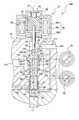
- the electromagnetic pressure regulating valve 14 includes a housing 21 as shown in FIG. In the housing 21, a primary port 21a, a valve body hole 21b, and a secondary port 21c are formed.
- the primary port 21a is connected to the electromagnetic shut-off valve 15 (see FIG. 1), and is connected to the valve body hole 21b via the primary side passage 21d formed in the housing 21.
- the valve element hole 21b extends along the axis L1 extending vertically.
- the valve body hole 21b has a circular cross section, and has a valve space 21e formed in a middle portion thereof with a diameter larger than that of the remaining portion.
- the primary side passage 21d is connected to the valve space 21e.
- the valve body hole 21b is connected to the secondary port 21c through a secondary side passage 21f formed in the housing 21.
- the secondary side passage 21f is connected to the valve body hole 21b in the secondary side region 21g above the valve space 21e.
- the secondary port 21c is connected to the fuel cell stack 3 through the hydrogen gas passage 12 (see FIG. 1).
- the primary port 21a and the secondary port 21c are connected via the primary side passage 21d, the valve space 21e, the secondary side region 21g, and the secondary side passage 21f.
- the primary passage 21d, the valve space 21e, the secondary region 21g, and the secondary passage 21f constitute a valve passage 22 that connects the primary port 21a and the secondary port 21c.
- the housing 21 has a seat 23.
- the seat portion 23 is located in the vicinity of an opening connecting the secondary side region 21g and the valve space 21e, and is formed so as to surround the opening.
- a valve body 24 is inserted into the housing 21 along the axis L1 of the valve body hole 21b, and the valve body 24 is in a state in which the upper end portion 24a, which is one end thereof, is inserted into the secondary side region 21g. Sitting on the seat 23.
- the valve body 24 has a substantially cylindrical shape, and the upper end portion 24 a is located in the secondary passage 21 f on the valve passage 22 side, that is, on the secondary port 21 a side of the valve passage 22.
- the valve body 24 has a tapered portion 24b on the upper end portion 24a side. The tapered portion 24b is tapered toward the upper side, and when the valve body 24 is in the closed position as shown in FIG. 2, the seat 24 is seated and the valve passage 22 is blocked. Yes.
- the housing 21 has a seal mounting portion 25 on the lower side of the valve space 21e.
- the seal attachment portion 25 is formed on the inner surface of the housing 21 over the entire circumference.
- the inner diameter of the seal mounting portion 25 substantially matches the hole diameter of the secondary side region 21g and the outer diameter of the valve body 24.
- the inner diameter of the housing 21 below the seal mounting portion 25 is larger than the inner diameter of the seal mounting portion 25.
- a generally annular bearing member accommodation space 26 is formed between the housing 21 and the valve body 24, and the bearing member 27 is accommodated in the bearing member accommodation space 26.
- the bearing member 27 is generally formed in a cylindrical shape, and is configured by, for example, a ball guide, a ball bearing, or a slide bearing.
- the bearing member 27 is externally mounted on the valve body 24 and interposed between the valve body 24 and the housing 21 to support the valve body 24.
- the bearing member 27 allows the valve body 24 to move smoothly in the vertical direction along the axis L1 in the housing 21.
- the bearing member 27 is grease-lubricated so as to further smooth the movement of the valve body 24 and improve durability.
- a high-pressure seal member 28 is provided on the upper side of the bearing member accommodation space 26 in which the bearing member 27 is arranged in this way so as to close it.
- the high-pressure seal member 28 that is the first seal member is a high-pressure seal that has a small frictional resistance and a small difference between the starting resistance and the sliding resistance, and is, for example, an O-ring that is surface-treated with a fluororesin or the like.
- the high-pressure seal member 28 is attached so as to be fitted into the inner peripheral portion of the seal attachment portion 25, and is disposed on the outer periphery of the valve body 24.
- the high-pressure seal member 28 arranged in this manner seals the gap between the valve body 24 and the seal attachment portion 25.
- a low pressure seal member 29 is provided in the seal mounting portion 25.
- the low-pressure seal member 29, which is the second seal member, is a substantially annular O-ring and is surface-treated with a resin or the like to reduce the frictional resistance.
- the low-pressure seal member 29 is located closer to the bearing member 27 than the high-pressure seal member 28 and is attached so as to be fitted into the inner peripheral portion of the seal attachment portion 25.
- the high pressure seal member 28 and the low pressure seal member 29 are arranged on the outer periphery of the valve body 24 in this order from the upper end side of the valve body 24 toward the lower end side (that is, from one end side to the other end side).
- the low pressure seal member 29 seals the gap between the seal mounting portion 25 and the valve body 24, and forms a buffer chamber 30 between the high pressure seal member 28 and the low pressure seal member 29. Hydrogen gas leaking from the high-pressure seal member 28 is guided to the buffer chamber 30 which is the first space.
- the high-pressure seal member 28 and the low-pressure seal member 29 may be attached so as to be fitted into the outer peripheral portion of the valve body
- a diaphragm seal 31 is provided below the bearing member accommodation space 26 so as to close the space.
- the diaphragm seal 31 that is the third seal member is a diaphragm that is formed in an approximately annular shape, and is disposed on the outer periphery of the valve body 24.
- the inner edge portion of the diaphragm seal 31 is attached to the valve body 24, and the outer edge portion is attached to the housing 21. More specifically, the inner edge portion of the diaphragm seal 31 is attached to the valve body 24 by being sandwiched between the lower end portion of the valve body 24 and the attachment member 24c attached thereto.
- the housing 21 is configured to be split into two vertically, and is attached to the housing 21 by sandwiching an outer edge portion of the diaphragm seal 31 between the two portions.
- the bearing member accommodation space 26 whose upper and lower sides are closed in this way is another space (for example, a valve space 21e, a secondary side region 21g, etc.) formed in the housing 21 by the two seal members 31 and 29. It is cut off and separated from.
- the bearing member accommodation space 26 as the second space is opened to the atmosphere by an atmosphere communication path 32 formed in the housing 21. Therefore, the grease that lubricates the bearing member 27 is not exposed to hydrogen gas, and does not leak to other spaces in the housing 21, such as the valve space 21e and the secondary port 21c. Therefore, it is possible to prevent the grease from being mixed into the hydrogen gas and to prevent the influence on the downstream equipment, to suppress the depletion of the grease, and to maintain the lubrication state of the bearing member 27. Thereby, while being able to improve the durability of the bearing member 27, the valve body 24 can be moved smoothly.
- a pressure feedback chamber 33 is formed below the diaphragm seal 31 in the valve body hole 21b.
- the pressure return chamber 33 is a substantially disk-shaped space surrounded by the bottom of the housing 21 and the diaphragm seal 31.
- the lower end portion which is the other end portion of the valve body 24 is located in the pressure feedback chamber 33 formed in the housing 21.
- a space between the pressure feedback chamber 33 and the bearing member accommodating space 26 is closed by a diaphragm seal 31, and the pressure feedback chamber 33 is formed in a housing-side pressure equalizing passage 34 (second pressure equalization passage) formed in the housing 21. Pressure passage) is connected to the secondary passage 21f.
- a valve-side pressure equalizing passage 35 is formed in the valve body 24.
- the valve-side pressure equalizing passage 35 which is the first pressure equalizing passage, has a secondary side communication portion 35a, a feedback portion 35b, and a communication portion 35c.
- the secondary side communication part 35a extends so as to penetrate the upper end part 24a of the valve body 24 in the radial direction, and both ends thereof open to the secondary side region 21g.
- the feedback portion 35 b extends so as to penetrate the valve body 24 in the radial direction, and both ends thereof open to the buffer chamber 30.
- the secondary side communication part 35a and the feedback part 35b are connected by a communication part 35c formed along the axis of the valve body 24 (substantially coincides with the axis L1 in this embodiment).
- the buffer chamber 30 is connected to the secondary region 21g via the valve-side pressure equalizing passage 35.
- the housing-side pressure equalizing passage 34 connects the secondary port 21 c and the pressure feedback chamber 33, and introduces the secondary pressure p 2 guided to the secondary port 21 c into the pressure feedback chamber 33.
- the valve-side pressure equalizing passage 35 connects the secondary port 21c and the buffer chamber 30 and guides hydrogen gas leaked into the buffer chamber 30 to the secondary port 21c.
- the electromagnetic pressure regulating valve 14 is a pressure regulating valve having a safety structure that returns hydrogen gas leaked from the primary side to the secondary side without leaking to the outside.
- the valve body 24 has a flange 24e.
- the flange 24e is formed over the entire circumference in the lower side of the tapered portion 24b and protrudes further outward in the radial direction from the tapered portion 24b.
- the flange 24e is positioned so as to face the upper end of the seal attachment portion 25.
- a return spring 36 is arranged between the flange 24e and the upper end of the seal mounting portion 25.
- the return spring 36 is a so-called compression coil spring, and is externally attached to the valve body 24 in a compressed state, and urges the valve body 24 in the closed position direction (the direction in which the valve body 24 moves toward the closed position).
- the urged valve body 24 is seated on the seat portion 23 and closes the valve passage 22.
- An electromagnetic proportional solenoid 37 is provided at the open end portion (that is, the upper end portion) of the housing 21 so as to apply a force against the urging force of the return spring 36 to the valve body 24.
- the electromagnetic proportional solenoid 37 which is a valve body driving means is screwed and fixed to the outer periphery of the opening end portion of the housing 21.
- the electromagnetic proportional solenoid 37 has a solenoid coil 38.
- the solenoid coil 38 is generally formed in a cylindrical shape, and the housing 21 is screwed to the lower end side thereof.
- the solenoid coil 38 has a substantially cylindrical case 38a, in which a bobbin 38b and a coil wire 38c are provided.
- the bobbin 38b is also formed in a substantially cylindrical shape, and the solenoid coil 38 is configured by winding the bobbin 38b around the coil wire 38c.
- the coil wire 38 c is electrically connected to the controller 18.
- a yoke 39 is provided at the lower end and the upper end is closed by the cover 40.
- a movable member 41 is provided between the yoke 39 and the cover 40.
- the movable member 41 is made of a magnetic material, is formed in a substantially cylindrical shape, and is disposed along the axis L1.
- the outer diameter of the movable member 41 is smaller than the inner diameter of the solenoid coil 38.
- An annular guide member 42 is interposed between the movable member 41 and the solenoid coil 38.
- the guide member 42 is made of a nonmagnetic material, and supports the movable member 41 so as to be slidable in the vertical direction along the axis L1.
- the yoke 39 faces the lower end portion of the movable member 41 in the vertical direction, and is positioned in a state of being spaced apart from each other.
- the yoke 39 is made of a magnetic material, for example, electromagnetic stainless steel, and is formed in an approximately annular shape.
- the yoke 39 and the movable member 41 are magnetized by passing a current through the solenoid coil 38, and the yoke 39 attracts the movable member 41.
- a compression coil spring 43 is provided between the upper end portion of the movable member 41 and the cover 40, and the movable member 41 is urged toward the valve body 24 by the compression coil spring 43.
- a pressing member 44 is provided at the lower end of the movable member 41. The pressing member 44 extends along the axis L ⁇ b> 1 and is inserted into the yoke 39. A proximal end portion of the pressing member 44 is fixed to the movable member 41. The front end of the pressing member 44 is formed in a partial spherical shape, and is biased by the compression coil spring 43 via the movable member 41 and pressed against the upper end portion 24 a of the valve body 24.
- the pressing member 44 arranged in this way pushes the valve body 24 in the open position direction with a force corresponding to the current by causing the current to flow through the solenoid coil 38 and attracting the movable member 41 toward the yoke 39. 22 is opened.
- the electromagnetic pressure regulating valve 14 configured as described above is guided from the hydrogen tank 11 to the valve space 21e by the taper portion 24b of the valve body 24 and the upper surface of the flange 24e (pressure receiving surface P1 corresponding to the first pressure receiving surface). and receiving the primary pressure p 1 in the open position direction, the lower surface of the flange 24e (pressure receiving surface P2 corresponding to the second pressure receiving surface), and receiving the primary pressure p 1 in the closed position.
- the pressure-receiving surface P1 is a partial region of the tapered surface, and is a region on the outer side in the radial direction from the secondary region 21g in plan view. In each pressure receiving surface P1, P2, the primary pressure p 1 are acting in a direction against each other and cancel each other.
- the pressure receiving areas of the pressure receiving surfaces P1, P2 are substantially the same because the lower end 24d side of the flange 24e of the valve body 24 and the inner diameter (that is, the seat diameter) of the secondary side region 21g have substantially the same outer diameter. It has become. Therefore, to prevent the action force by the primary pressure p 1 received by the pressure receiving surface P1, and the acting force by the primary pressure p 1 received by the pressure receiving surface P2 are canceled with each other, the effects of changes in primary pressure p 1 in the valve body 24 Can do.
- electromagnetic pressure regulating valve 14 receiving the secondary pressure p 2 flowing secondary side area 21g in the tapered surface of the upper end and the tapered portion 24b of the valve element 24 (pressure receiving surface P3) in the open position direction, the diaphragm seal 31 and guided to the pressure feedback chamber 33 secondary pressure p 2 at the lower end 24d (pressure receiving surface P4) of the valve body 24 receives the pressure in the closed position.
- the pressure receiving surface P4 is a region overlapping the secondary side region 21g in plan view. Secondary pressure p 2 to the pressure receiving in pressure receiving surface P3, P4 is acting in a direction against each other.
- the valve body 24 has an outer diameter r 2 that is substantially the same as the seat diameter r 1 , whereas the effective diameter r 3 of the diaphragm seal 31 is the seat diameter r 1 and the outer diameter r 2 of the valve body 24. It is getting bigger. Therefore, the pressure receiving area of the pressure receiving surface P4 is larger by the effective area of the diaphragm seal 31 than the pressure receiving surface P3. Thus, the valve element 24, the action force due to the secondary pressure p 2 received by the pressure receiving surface P3, P4 is not completely canceled, the action force corresponding to the difference between the pressure receiving areas of each pressure receiving surface P3, P4 is closed Acts in the direction of the position.
- the valve body 24 is urged by the return spring 36 in the closed position direction and is seated on the seat portion 23.
- the electromagnetic pressure regulating valve 14 is configured as a normally closed type valve. Thereby, the valve passage 22 can be urgently cut off by cutting off the current flowing through the solenoid coil 38.
- the electromagnetic pressure regulating valve 14 is configured such that when a current is passed through the solenoid coil 38, the valve body 24 is pushed by the pressing member 44 to open the valve passage (that is, the push type electromagnetic pressure regulating valve 14). Pressure valve).
- the hydrogen gas in the secondary side region 21g is discharged from the secondary port 21c through the secondary side passage 21f and led to the pressure feedback chamber 33 through the housing side pressure equalizing passage 34.
- the diaphragm seal 31 receives the secondary pressure p 2 of the hydrogen gas guided to the pressure feedback chamber 33.
- the opening degree of the valve passage 22 so that the force is balanced i.e., opening degree of the orifice
- pressure secondary pressure p 2 is corresponding to the operation amount of the accelerator pedal, that is controlled to the target pressure.
- the exciting force becomes larger than the action force by the secondary pressure p 2
- the valve element 24 seats It moves in the open position direction away from the part 23.
- the valve element 24, the action force due to the secondary pressure p 2, the excitation force, the spring force of the compression coil spring 43, and the spring force is to where balance of the return spring 36, the opening degree of the valve passage 22 with it spread secondary pressure p 2 rises.
- the secondary pressure p 2 is pressure adjusted to the target pressure.
- the electromagnetic pressure regulating valve 14 can control the opening degree of the valve passage 22 in accordance with it and can regulate the secondary pressure p 2 to the target pressure. Therefore, the high pressure hydrogen gas can be regulated with high accuracy to the low pressure target pressure by the electromagnetic pressure regulating valve 14 alone.
- the accelerator pedal is operated to change its operation amount and the target pressure received by the controller 18 changes. That is, when the target pressure changes, the current flowing through the solenoid coil 38 by the controller 18 increases or decreases, and the excitation force increases or decreases.
- the excitation force is applied by the secondary pressure p 2 , the spring force of the compression coil spring 43, and The valve body 24 moves to a position where the spring force of the return spring 36 is balanced, and the opening degree of the valve passage 22 is adjusted.
- the pressure is adjusted to suit the target pressure secondary pressure p 2 is changed.
- electromagnetic pressure regulating valve 14 by regulating to follow the target pressure varying from secondary pressure p 2, can be held more target pressure.
- electromagnetic pressure regulating valve 14 since the pressure receiving area of the pressure receiving surface P1 and the pressure receiving surface P2 substantially the same, it is canceled acting force the valve element 24 receives from the primary pressure p 1. Thus, it is possible to suppress the variation of the secondary pressure p 2 due to variations in the primary pressure p 1. Therefore, it is possible to improve the pressure controllability for high-pressure hydrogen gas, the secondary pressure p 2 can be controlled in a conventional electromagnetic pressure regulating valve as well as high precision. In addition, by canceling the action force received from the primary pressure p 1, it is possible to reduce the excitation force of the electromagnetic proportional solenoid 37, it is possible to miniaturize an electromagnetic pressure regulating valve 14.
- the electromagnetic pressure regulating valve 14 is operated from the valve space 21 e in the high pressure seal member 28 due to an unintended external factor during operation. Hydrogen gas may leak slightly into the buffer chamber 30.
- the buffer chamber 30 is connected to the secondary side region 21g through the valve-side pressure equalizing passage 35, and the hydrogen gas leaked from the high-pressure seal member 28 is discharged from the secondary port by the electromagnetic pressure regulating valve 14 to generate fuel.
- the safety structure leads to the battery stack.
- the buffer chamber 30 is connected with the secondary side area
- the low pressure seal member 29 can sufficiently prevent the hydrogen gas from leaking into the bearing member accommodation space 26. That is, hydrogen gas can be prevented from leaking out to the atmosphere via the bearing member accommodation space 26.
- the diaphragm seal 31 sliding friction when the valve body 24 is moved can be eliminated. Further, by adopting the low-pressure seal member 29 having a low frictional resistance, sliding friction can be suppressed as much as possible. Thus, the valve body 24 can be smoothly moved by suppressing the sliding friction which acts on the valve body 24. As a result, the secondary pressure can be quickly adjusted to the target pressure, and the response of the secondary pressure is improved. Further, by adopting the high-pressure sealing member 28, the withstand voltage performance is improved with respect to the primary pressure p 1 of the electromagnetic pressure regulating valve 14.
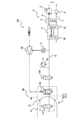
- the hydrogen gas supply apparatus 1A according to the second embodiment is similar in configuration to the hydrogen gas supply apparatus 1 according to the first embodiment, but the hydrogen gas supply apparatus 1A is configured to receive pressure of an electromagnetic pressure regulating valve 14 provided therein. It differs from the hydrogen gas supply device 1 according to the first embodiment in that the area A1 and the pressure receiving area A2 are different as shown in FIG. This will be described in detail below.
- the outer diameter r 2 of the valve body 14A is smaller than the seat diameter r 1. Therefore, the pressure receiving area of the pressure receiving surface P1 is smaller than the pressure receiving area of the pressure receiving surface P2. Therefore, the acting force by the primary pressure p 1 according to the difference between the pressure receiving area of the pressure receiving surface P1 and the pressure receiving area of the pressure receiving surface P2 acts on the valve body 24 toward the closed position. Therefore, the speed toward the closed position of the valve body 24A when the current flowing through the solenoid coil 38 is interrupted is increased, and the interrupting performance is improved.
- the electromagnetic pressure regulating valve 14A can firmly close the valve passage 22 so that the fuel gas does not leak from the primary side to the secondary side.
- the hydrogen gas supply device 1A according to the second embodiment has the same effects as the hydrogen gas supply device 1 according to the first embodiment.
- the hydrogen gas supply device 1B according to the third embodiment is similar in configuration to the hydrogen gas supply device 1 according to the first embodiment. Therefore, the configuration of the hydrogen gas supply device 1B according to the third embodiment will be described only with respect to differences from the hydrogen gas supply device 1 according to the first embodiment.
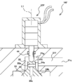
- the hydrogen gas supply device 1B provided in the fuel cell system 2B includes an electromagnetic pressure regulating valve 14B.
- the electromagnetic pressure regulating valve 14 ⁇ / b> B is an on-tank pressure regulating valve and is disposed at the opening of the hydrogen tank 11.
- the electromagnetic pressure regulating valve 14B has the same configuration as the electromagnetic pressure regulating valve 14 of the first embodiment, and includes a housing 21 (see FIG. 2) molded integrally with the valve block 50.
- the valve block 50 is attached in a state where a seal is achieved in the opening of the hydrogen tank 11 (see FIG. 4).
- the electromagnetic pressure regulating valve 14B has a function of regulating the high-pressure hydrogen gas flowing out from the hydrogen tank 11 to a low pressure and supplying it to the fuel cell stack 3. . Therefore, by providing at the opening of the hydrogen tank 11, the output pressure level from the hydrogen tank 11 becomes low, and the safety of the hydrogen gas supply device 1B is greatly improved.
- An electromagnetic shut-off valve 15 is provided on the upstream side of the electromagnetic pressure regulating valve 14B.
- the electromagnetic shut-off valve 15 is provided integrally with the valve block 50 together with the electromagnetic pressure regulating valve 14B.
- the electromagnetic shut-off valve 15 and the electromagnetic pressure regulating valve 14B constitute an electromagnetic container base valve 51.
- an electromagnetic shut-off valve 15B is provided on the downstream side of the electromagnetic pressure regulating valve 14B.
- the electromagnetic shut-off valve 15B is a low-pressure solenoid valve having a function of opening and closing the hydrogen gas passage 12 in the same manner as the electromagnetic shut-off valve 15. Since a low-pressure solenoid valve can be adopted as the electromagnetic shut-off valve 15B, the manufacturing cost of the electromagnetic shut-off valve 15B can be made lower than that of the electromagnetic shut-off valve 15.
- the electromagnetic shut-off valve 15B is, for example, a direct drive type solenoid valve that opens only at a specified pressure or less and is inexpensive to manufacture (the solenoid solenoid does not open when the thrust exceeds the specified pressure by reducing the thrust of the solenoid).
- a single-stage solenoid valve is desirable. This is because, when the vehicle (fuel cell system 2B) is stopped, if any abnormality occurs in the electromagnetic pressure regulating valve 14B (for example, leakage of high-pressure hydrogen gas due to an unintended external factor during operation), the electromagnetic pressure regulating valve If the pressure on the upstream side of 15B becomes high and the pressure on the upstream side exceeds the specified pressure, the electromagnetic shut-off valve 15B will not open when the vehicle is next started.
- the electromagnetic cutoff valve 15B when a direct drive type electromagnetic valve is used as the electromagnetic cutoff valve 15B, hydrogen gas having a pressure exceeding a specified pressure can be prevented from flowing into the fuel cell stack 3. Thereby, the fuel cell stack 3 can be protected. Further, since the electromagnetic shut-off valve 15B does not open, it is possible to detect and detect an abnormality of the electromagnetic pressure regulating valve without using a pressure sensor.
- the hydrogen gas supply device 1B according to the third embodiment has the same effects as the hydrogen gas supply device 1 according to the first embodiment.
- the hydrogen gas supply device 1C according to the fourth embodiment is similar in configuration to the hydrogen gas supply device 1B according to the third embodiment. Therefore, the configuration of the hydrogen gas supply device 1C according to the fourth embodiment will be described only with respect to differences from the hydrogen gas supply device 1B according to the third embodiment.
- the electromagnetic shut-off valve 15B is removed as shown in FIG.
- the electromagnetic pressure regulating valve 14B is a normally closed valve, and shuts off the hydrogen gas passage 12 when the pressure on the downstream side becomes equal to or higher than a specified pressure. Therefore, even when the electromagnetic shut-off valve 15B is removed as in the hydrogen gas supply device 1C, it is possible to prevent hydrogen gas having a pressure exceeding the specified pressure from flowing through the fuel cell stack 3.
- the hydrogen gas supply device 1C according to the fourth embodiment has the same effects as the hydrogen gas supply device 1B according to the third embodiment.
- the hydrogen gas supply device 1D according to the fifth embodiment is similar in configuration to the hydrogen gas supply device 1 according to the first embodiment. Therefore, the configuration of the hydrogen gas supply device 1D according to the fifth embodiment will be described only with respect to differences from the hydrogen gas supply device 1 according to the first embodiment.
- the hydrogen gas supply device 1D provided in the fuel cell system 2D includes an electromagnetic pressure regulating valve 14D as shown in FIG.
- the electromagnetic pressure regulating valve 14 ⁇ / b> D is an in-tank pressure regulating valve and is provided in the opening of the hydrogen tank 11.
- the electromagnetic pressure regulating valve 14D has a function of regulating the high-pressure hydrogen gas flowing out from the hydrogen tank 11 to a low pressure and supplying it to the fuel cell stack 3 in the same manner as the electromagnetic pressure regulating valve 14 of the first embodiment. .
- the in-tank of the electromagnetic pressure regulating valve 14D in the hydrogen tank 11 and the output pressure level from the hydrogen tank 11 become low, and the safety of the hydrogen gas supply device 1D is further greatly improved.
- an electromagnetic shut-off valve 15D is disposed on the downstream side of the electromagnetic pressure regulating valve 14D. Therefore, a low-pressure electromagnetic cutoff valve can be used as the electromagnetic cutoff valve 15D.
- the hydrogen gas supply device 1D according to the fifth embodiment has the same effects as the hydrogen gas supply device 1 according to the first embodiment.
- the hydrogen gas supply device 1E according to the sixth embodiment is similar in configuration to the hydrogen gas supply device 1D according to the fifth embodiment. Therefore, the configuration of the hydrogen gas supply device 1E according to the fifth embodiment will be described only with respect to differences from the hydrogen gas supply device 1D according to the fifth embodiment.
- the electromagnetic shut-off valve 15D is removed as shown in FIG.
- the electromagnetic pressure regulating valve 14D is a normally closed valve, and shuts off the hydrogen gas passage 12 when the downstream pressure becomes equal to or higher than a specified pressure. Therefore, even when the electromagnetic shut-off valve 15B is removed as in the hydrogen gas supply device 1E, hydrogen gas having a pressure exceeding the specified pressure can be prevented from flowing into the fuel cell stack 3.
- the hydrogen gas supply device 1E according to the sixth embodiment has the same effects as the hydrogen gas supply device 1D according to the fifth embodiment.
- the hydrogen gas supply device 1F according to the seventh embodiment has a pressure regulating valve 14F as shown in FIG.
- the pressure regulating valve 14F includes a piezoelectric actuator 37F instead of the electromagnetic proportional solenoid 37.
- the piezoelectric actuator 37F is composed of a piezoelectric element (for example, a piezo element), generates a driving force according to the applied voltage, moves the valve body 24 in the open position direction via the pressing member 44, and moves the valve passage 22 through the valve passage 22. It is supposed to open. At this time, the valve passages 22 is opened at the opening corresponding to the drive force generated, electromagnetic pressure regulating valve 14F is also pressure regulating the secondary pressure p 2 in the pressure corresponding to the voltage applied to the piezoelectric actuator 37F It can be done.
- the hydrogen gas supply device 1F according to the seventh embodiment has the same configuration as the hydrogen gas supply device 1 according to the first embodiment, and has the same effects.
- a hydrogen gas supply device 1G according to the eighth embodiment has a pressure regulating valve 14G as shown in FIG.
- the pressure regulating valve 14G includes a force motor 37G instead of the electromagnetic proportional solenoid 37.
- a movable coil 62 is inserted into a cylindrical permanent magnet 61, and when a current is passed through the movable coil 62, an excitation force corresponding to the current is generated. 63 is moved downward.
- the valve member 24 is pushed in the open position direction by the pressing member 44 provided integrally therewith, and the valve passage 22 is opened.
- the valve passages 22 is opened at opening corresponding to the excitation force generated, regulating valve 14G is also adapted to be pressure adjusted secondary pressure p 2 in the pressure corresponding to current flowing in the force motor 37G Yes.
- the hydrogen gas supply device 1G according to the eighth embodiment has the same configuration as the hydrogen gas supply device 1 according to the first embodiment, and has the same effects.
- the secondary pressure p 2 in the pressure feedback chamber 33 is pressure in the diaphragm seal 31 may not necessarily be a diaphragm seal may be a low-pressure sealing member such as an O-ring.
- a diaphragm seal may be a low-pressure sealing member such as an O-ring.
- the electromagnetic pressure regulating valve 14 of the present embodiment is a push type electromagnetic pressure regulating valve, but may be a pull type electromagnetic pressure regulating valve.
- the two pressure equalizing passages 34 and 35 are separately formed in the housing 21 and the valve body 24, but the two pressure equalizing passages 34 and 35 are either one of the valve body 24 and the housing 21.
- the electromagnetic pressure regulating valves 14, 14A, 14B, and 14D control the opening degree of the valve passage 22 by adjusting the current that flows to the electromagnetic proportional solenoid 37 that is the valve body driving means.
- the opening degree of the valve passage 22 may be controlled by adjusting the voltage applied to the electromagnetic proportional solenoid 37. The same applies to other valve body driving means.
- the present invention can be applied to a hydrogen gas supply device of a fuel cell system that supplies hydrogen gas to a fuel cell stack.
Landscapes
- Engineering & Computer Science (AREA)
- General Engineering & Computer Science (AREA)
- Mechanical Engineering (AREA)
- Physics & Mathematics (AREA)
- Chemical Kinetics & Catalysis (AREA)
- Sustainable Development (AREA)
- Sustainable Energy (AREA)
- Chemical & Material Sciences (AREA)
- Manufacturing & Machinery (AREA)
- Electrochemistry (AREA)
- General Chemical & Material Sciences (AREA)
- Life Sciences & Earth Sciences (AREA)
- Fluid Mechanics (AREA)
- General Physics & Mathematics (AREA)
- Automation & Control Theory (AREA)
- Fuel Cell (AREA)
- Magnetically Actuated Valves (AREA)
Abstract
Description
しかしながら、摺動シール部にダイヤフラムシール方式を使用した場合、ダイヤフラムは一般的に十分な耐圧力強度を有していないため、上流側圧力が高圧になると破損に至る恐れがある。また、ダイヤフラムシール方式の代わりにOリングシール方式を使用することも考えられる。この場合には、電磁式調圧弁作動中に上流側圧力が高圧になると、意図しない外的要因により水素漏れに至る恐れがある。
<燃料電池システム>
燃料電池システム2は、燃料電池自動車等の車両に設けられており、車両の駆動輪を駆動する駆動源、例えばモータに電力を供給するようになっている。燃料電池システム2は、燃料電池スタック3と、エア供給装置4と、水素ガス供給装置1とを備えている。燃料電池スタック3は、カソード極3aとアノード極3bとを有しており、カソード極3a及びアノード極3bにエア及び水素ガスが夫々供給されることで発電するようになっている。また、燃料電池スタック3は、アノード極3bに供給する水素ガスの供給圧を調圧することで、その発電量を調整することができるようになっている。このように構成される燃料電池スタック3のカソード極3aには、エア供給装置4が接続され、アノード極3bには、水素ガス供給装置1が接続されている。
エア供給装置4は、カソード極3aに大気中のエアを供給するようになっており、コンプレッサ5と、エア供給通路6と、エア排出通路7と、エア調圧弁8とを備えている。コンプレッサ5は、エア供給通路6を介してカソード極3aに繋がっており、大気中のエアを加圧してカソード極3aに供給するようになっている。また、カソード極3aには、エア排出通路7が繋がっており、このエア排出通路7は、エア調圧弁8を介して大気に開放されている。エア調圧弁8は、エアコンプレッサ5と連動してカソード極3aに供給するエアの供給圧を調圧する機能を有している。またエア供給通路6及びエア排出通路7には、加湿器9が設けられており、加湿器9は、エア排出通路7を流れるエアから吸湿し、その吸湿によって得た水分によりエア供給通路6を流れるエアを加湿するようになっている。
水素ガス供給装置1は、アノード極3bに水素ガスを供給するようになっており、水素タンク11と、水素ガス通路12と、タンク用圧力センサ13と、電磁式調圧弁14と、電磁式遮断弁15と、安全リリーフ弁16と、通路用圧力センサ17と、制御器18とを備えている。水素タンク11は、いわゆる高圧タンクであり、例えば35MPa又は70MPaの高圧の水素ガスを貯蔵できるようになっており、その内圧に応じた信号がタンク用圧力センサ13から出力されている。また、水素タンク11は、水素ガス通路12を介してアノード極3bに繋がっており、この水素ガス通路12には、電磁式調圧弁14が介在している。電磁式調圧弁14の具体的な構成については後述するが、電磁式調圧弁14は、水素タンク11から流出する高圧の水素ガスを低圧に調圧して燃料電池スタック3に供給する機能を有している。また、水素ガス通路12の電磁式調圧弁14より上流側には、電磁式遮断弁15が介在している。
電磁式調圧弁14は、図2に示すようにハウジング21を備えている。ハウジング21には、一次ポート21a、弁体孔21b、及び二次ポート21cが形成されている。一次ポート21aは、電磁式遮断弁15(図1参照)に繋がっており、ハウジング21に形成されている一次側通路21dを介して弁体孔21bに繋がっている。
以下では、図2を参照しながら電磁式調圧弁14の動作について説明する。車両のアクセルペダルが操作されると、その操作量に応じた電流(つまり、目標圧力に応じた電流)が制御器18からソレノイドコイル38に流される。そうすると、可動部材41に励磁力が作用し、可動部材41がヨーク39の方へ吸引される。これにより、押圧部材44によって弁体24が開位置方向に押されて座部23から離れる。そうすると、弁通路22が開かれ、弁空間21eの水素ガスが二次側領域21gへと流れる。この際、弁体24と座部23との間に形成されるオリフィス(図示せず)により弁空間21eから二次側領域21gに流れる水素ガスが二次圧p2に減圧される。このように、電磁式調圧弁14は、ソレノイドコイル38に電流を流すと、弁体24が押圧部材44によって押されて弁通路が開くように構成されている(つまり、プッシュ型の電磁式調圧弁である)。
第2実施形態に係る水素ガス供給装置1Aは、第1実施形態に係る水素ガス供給装置1と構成が類似しているが、水素ガス供給装置1Aは、そこに備わる電磁式調圧弁14の受圧面積A1及び受圧面積A2が図3に示すように異なっているという点で第1実施形態に係る水素ガス供給装置1と異なっている。以下では、その点について詳述する。
第3実施形態に係る水素ガス供給装置1Bは、第1実施形態に係る水素ガス供給装置1と構成が類似している。従って、第3実施形態に係る水素ガス供給装置1Bの構成について、第1実施形態に係る水素ガス供給装置1と異なる点についてだけ説明する。
第4実施形態に係る水素ガス供給装置1Cは、第3実施形態に係る水素ガス供給装置1Bと構成が類似している。従って、第4実施形態に係る水素ガス供給装置1Cの構成について、第3実施形態の水素ガス供給装置1Bと異なる点についてだけ説明する。
第5実施形態に係る水素ガス供給装置1Dは、第1実施形態に係る水素ガス供給装置1と構成が類似している。従って、第5実施形態に係る水素ガス供給装置1Dの構成について、第1実施形態の水素ガス供給装置1と異なる点についてだけ説明する。
第6実施形態に係る水素ガス供給装置1Eは、第5実施形態に係る水素ガス供給装置1Dと構成が類似している。従って、第5実施形態に係る水素ガス供給装置1Eの構成について、第5実施形態の水素ガス供給装置1Dと異なる点についてだけ説明する。
第7実施形態に係る水素ガス供給装置1Fは、図8に示すような調圧弁14Fを有している。調圧弁14Fは、電磁比例ソレノイド37に代えて圧電アクチュエータ37Fを備えている。圧電アクチュエータ37Fは、圧電素子(例えば、ピエゾ素子)から成り、印加される印加電圧に応じた駆動力を発生し、押圧部材44を介して弁体24を開位置方向に動かして弁通路22を開くようになっている。この際、弁通路22は、発生する駆動力に応じた開度で開き、電磁式調圧弁14Fもまた、圧電アクチュエータ37Fに印加される印加電圧に応じた圧力に二次圧p2を調圧できるようになっている。
第8実施形態に係る水素ガス供給装置1Gは、図9に示すような調圧弁14Gを有している。調圧弁14Gは、電磁比例ソレノイド37に代えてフォースモータ37Gを備えている。フォースモータ37Gは、円筒状の永久磁石61の中に可動コイル62が挿入されており、可動コイル62に電流を流すと電流に応じた励磁力が発生し、この励磁力により可動コイル62がヨーク63内を下方に動くようになっている。可動コイル62が下方に動くことでそれに一体的に設けられている押圧部材44によって弁体24が開位置方向に押されて弁通路22が開く。この際、弁通路22は、発生する励磁力に応じた開度で開き、調圧弁14Gもまたフォースモータ37Gに流される電流に応じた圧力に二次圧p2を調圧できるようになっている。
本実施形態では、圧力帰還室33の二次圧p2をダイヤフラムシール31で受圧しているが、必ずしもダイヤフラムシールでなくてもよく、Oリングなどの低圧シール部材であってもよい。この場合、弁体24の下端側の外径をシート径より大きくすることによって、第1実施形態の電磁式調圧弁14と同様の作用効果を達成することができる。
また、電磁式調圧弁14,14A,14B,14Dは、弁体駆動手段である電磁比例ソレノイド37に流す電流を調整することにより弁通路22の開度を制御できるようになっているが、電磁比例ソレノイド37に印加する電圧を調整することにより弁通路22の開度を制御してもよい。他の弁体駆動手段の場合も同様である。
2,2B~2G 燃料電池システム
3 燃料電池スタック
11 水素タンク
12 水素ガス通路
14,14A,14B,14D 電磁式調圧弁
14F,14G 調圧弁
15,15B,15D 電磁式遮断弁
17 通路用圧力センサ
18 制御器
21 ハウジング
21a 一次ポート
21c 二次ポート
22 弁通路
24,24A 弁体
24a 上端部
26 軸受部材収容空間
28 高圧シール部材
29 低圧シール部材
30 バッファ室
31 ダイヤフラムシール
32 大気連通路
33 圧力帰還室
34 ハウジング側均圧通路
35 弁側均圧通路
37 電磁比例ソレノイド
37F 圧電アクチュエータ
37G フォースモータ
Claims (13)
- 燃料電池スタックに水素ガスを供給する燃料電池システムの水素ガス供給装置において、
高圧の水素ガスが貯蔵される水素タンクと低圧の水素ガスが消費される燃料電池スタックとを接続する水素ガス通路と、
前記水素ガス通路に設けられ、前記水素タンクから流出する水素ガスの圧力を調圧して前記燃料電池スタックに供給する調圧弁とを備え、
前記調圧弁は、
前記水素タンクに接続される一次ポート及び前記燃料電池スタックに接続される二次ポートを繋ぐ弁通路を有するハウジングと、
前記ハウジング内に設けられ、前記弁通路を閉じる閉位置と前記弁通路を開く開位置との間で移動して前記弁通路の開度を制御する弁体と、
前記弁体の外周に配置される第1シール部材及び第2シール部材とを備え、
前記弁体の一端側は、前記弁通路側に位置し、前記弁体の他端側は、前記ハウジング内に形成される圧力帰還室内に位置し、
前記第1シール部材及び第2シール部材は、前記弁体の一端側から前記弁体の他端側に向ってこの順序で配置されており、
前記第1シール部材と前記第2シール部材との間に形成された第1の空間と二次ポートとを繋ぐ第1の均圧通路を更に備えている、燃料電池システムの水素ガス供給装置。 - 前記調圧弁は、前記二次ポートと前記圧力帰還室とを繋ぐ第2の均圧通路を備え、
前記弁体は、前記弁体が開位置に向かう開位置方向に前記二次ポートの圧力が作用する二次側受圧部と、前記弁体が閉位置に向かう閉位置方向に前記圧力帰還室の圧力が作用する圧力帰還室側受圧部とを有する、請求項1に記載の燃料電池システムの水素ガス供給装置。 - 前記調圧弁は、
前記弁体の外周において、前記第2シール部材より前記弁体の他端側に配置される第3シール部材と、
前記第3シール部材と前記第2シール部材との間にされた第2の空間と、
前記第2空間に収容される軸受部材と、
前記第2空間と大気とを繋ぐ大気連通路とを更に有する、請求項2に記載の燃料電池システムの水素ガス供給装置。 - 前記圧力帰還室側受圧部の受圧面積は、前記二次側受圧部の受圧面積よりも大きい、請求項3に記載の燃料電池システムの水素ガス供給装置。
- 前記第3シール部材は、ダイヤフラムシールであり、
前記ダイヤフラムシールは、前記弁体の他端側に設けられ、該他端部と共に前記圧力帰還室側受圧部を構成する、請求項3又は4に記載の燃料電池システムの水素ガス供給装置。 - 前記弁体は、前記一次ポートに導かれる一次圧を前記開位置方向に受圧する第1受圧面と前記一次圧を前記閉位置方向に受圧する第2受圧面とを有し、
前記第1受圧面の受圧面積は、前記第2受圧面の受圧面積と同一である、請求項3乃至5の何れか1つに記載の燃料電池システムの水素ガス供給装置。 - 前記弁体は、前記一次ポートに導かれる一次圧を前記開位置方向に受圧する第1受圧面と前記一次圧を前記閉位置方向に受圧する第2受圧面とを有し、
前記第1受圧面の受圧面積は、前記第2受圧面の受圧面積より小さい、請求項3乃至5の何れか1つに記載の燃料電池システムの水素ガス供給装置。 - 前記調圧弁は、
前記弁体を前記閉位置方向に付勢する復帰用ばねと、
印加される印加電圧又は印加電流に応じた駆動力を前記復帰用ばねの付勢に抗するように前記弁体に与えて該弁体を前記開位置方向に移動させる弁体駆動手段とを有し、
前記調圧弁は、前記弁体駆動手段への印加電圧又は印加電流の印加を止めると前記復帰用ばねにより前記弁体が前記閉位置方向へ移動するノーマルクローズ形の弁である、請求項3乃至7の何れか1つに記載の燃料電池システムの水素ガス供給装置。 - 前記水素ガス通路において前記調圧弁より下流側に設けられ、前記燃料電池スタックに供給される前記水素ガスの圧力を検出する圧力検出手段と、
前記圧力検出手段で検出される圧力に応じて前記弁体駆動手段に印加する印加電圧又は印加電流を制御して二次圧を前記燃料電池スタックの目標圧力にする制御手段とを更に備える、請求項8に記載の燃料電池システムの水素ガス供給装置。 - 前記制御手段は、前記圧力検出手段で検出される圧力が予め定められた規定圧力以上になると、前記弁体駆動手段に印加する印加電圧又は印加電流を制御して前記弁体を前記閉位置に移動させる、請求項9に記載の燃料電池システムの水素ガス供給装置。
- 前記調圧弁は、前記弁体駆動手段が前記高圧タンクの供給口に設置されるインタンク型又はオンタンク型の容器元弁である、請求項8乃至10の何れか1つに記載の燃料電池システムの水素ガス供給装置。
- 前記水素ガス通路において前記調圧弁より上流側に設けられ、前記調圧弁への水素ガスの供給を遮断可能な電磁式遮断弁を更に備える、請求項1乃至11の何れか1つに記載の燃料電池システムの水素ガス供給装置。
- 前記水素ガス通路において前記調圧弁より下流側に設けられ、前記燃料電池スタックへの水素ガスの供給を遮断可能な電磁式遮断弁を更に備える、請求項1乃至11の何れか1つに記載の燃料電池システムの水素ガス供給装置。
Priority Applications (5)
| Application Number | Priority Date | Filing Date | Title |
|---|---|---|---|
| CN201180037245.6A CN103180645B (zh) | 2010-08-06 | 2011-08-04 | 燃料电池系统的氢气供给装置 |
| US13/814,010 US9831507B2 (en) | 2010-08-06 | 2011-08-04 | Hydrogen gas supply device of fuel cell system |
| KR1020137005807A KR101479882B1 (ko) | 2010-08-06 | 2011-08-04 | 연료전지 시스템의 수소 가스 공급 장치 |
| EP11814300.7A EP2602523B1 (en) | 2010-08-06 | 2011-08-04 | Hydrogen gas supply device of fuel cell system |
| JP2012527601A JP5458178B2 (ja) | 2010-08-06 | 2011-08-04 | 燃料電池システムの水素ガス供給装置 |
Applications Claiming Priority (2)
| Application Number | Priority Date | Filing Date | Title |
|---|---|---|---|
| JP2010177857 | 2010-08-06 | ||
| JP2010-177857 | 2010-08-06 |
Publications (1)
| Publication Number | Publication Date |
|---|---|
| WO2012017665A1 true WO2012017665A1 (ja) | 2012-02-09 |
Family
ID=45559184
Family Applications (1)
| Application Number | Title | Priority Date | Filing Date |
|---|---|---|---|
| PCT/JP2011/004436 Ceased WO2012017665A1 (ja) | 2010-08-06 | 2011-08-04 | 燃料電池システムの水素ガス供給装置 |
Country Status (6)
| Country | Link |
|---|---|
| US (1) | US9831507B2 (ja) |
| EP (1) | EP2602523B1 (ja) |
| JP (1) | JP5458178B2 (ja) |
| KR (1) | KR101479882B1 (ja) |
| CN (1) | CN103180645B (ja) |
| WO (1) | WO2012017665A1 (ja) |
Cited By (3)
| Publication number | Priority date | Publication date | Assignee | Title |
|---|---|---|---|---|
| WO2014103649A1 (ja) * | 2012-12-27 | 2014-07-03 | 日産自動車株式会社 | 調圧装置及び燃料電池システム |
| JP2021119525A (ja) * | 2017-01-23 | 2021-08-12 | 訓範 津田 | 水素流量制御装置 |
| JP2023155774A (ja) * | 2022-04-11 | 2023-10-23 | トヨタ自動車株式会社 | 燃料電池システム |
Families Citing this family (14)
| Publication number | Priority date | Publication date | Assignee | Title |
|---|---|---|---|---|
| CA2938738C (en) * | 2014-02-26 | 2021-11-16 | Zodiac Aerotechnics | Gas pressure reducer with electrically-powered master system |
| KR101646112B1 (ko) * | 2014-03-24 | 2016-08-05 | 현대자동차 주식회사 | 연료전지 시스템용 솔레노이드 밸브 |
| KR101806690B1 (ko) * | 2016-04-26 | 2017-12-07 | 현대자동차주식회사 | 연료전지 시스템의 연료극 배출밸브 |
| JP6800790B2 (ja) * | 2017-03-21 | 2020-12-16 | 愛三工業株式会社 | 車両用燃料電池システム |
| FR3080431B1 (fr) * | 2018-04-24 | 2020-05-08 | Commissariat A L'energie Atomique Et Aux Energies Alternatives | Dispositif fluidique d’alimentation en fluide d’interet |
| JP7175208B2 (ja) * | 2019-01-31 | 2022-11-18 | 川崎重工業株式会社 | ガス用電磁弁 |
| JP7266415B2 (ja) * | 2019-01-31 | 2023-04-28 | 川崎重工業株式会社 | ガス用電磁弁 |
| JP7457543B2 (ja) * | 2020-03-17 | 2024-03-28 | 株式会社小糸製作所 | 電磁弁および電磁弁を備える車両用クリーナシステム |
| IT202000005917A1 (it) * | 2020-03-19 | 2021-09-19 | Metatron S P A | Sistema di cella a combustibile e regolatore elettronico di pressione di combustibile per tale sistema |
| KR102279256B1 (ko) | 2020-04-07 | 2021-07-20 | 군산대학교산학협력단 | 홈이 형성된 이동체를 구비하는 유체 공급용 유량 조절용 밸브 |
| KR102274726B1 (ko) | 2020-04-07 | 2021-07-09 | 군산대학교산학협력단 | 유체 공급용 유량 조절용 밸브 |
| CN113833861A (zh) * | 2020-06-23 | 2021-12-24 | 株式会社捷太格特 | 阀装置 |
| CN112197023A (zh) * | 2020-10-26 | 2021-01-08 | 无锡伟博汽车科技有限公司 | 一种供氢比例电磁阀 |
| DE102023117736A1 (de) * | 2023-07-05 | 2025-01-09 | Deutsches Zentrum für Luft- und Raumfahrt e.V. | Anodenmodul und Polymerelektrolytbrennstoffzellensystem |
Citations (11)
| Publication number | Priority date | Publication date | Assignee | Title |
|---|---|---|---|---|
| JPH0634143U (ja) * | 1992-09-30 | 1994-05-06 | フジオーゼックス株式会社 | 排気ブレーキ用バタフライバルブ装置 |
| JPH09269836A (ja) * | 1996-03-29 | 1997-10-14 | Osaka Gas Co Ltd | 圧力制御弁 |
| JP2002243058A (ja) * | 2001-02-19 | 2002-08-28 | Saginomiya Seisakusho Inc | 電磁制御弁 |
| JP2002295709A (ja) * | 2001-03-29 | 2002-10-09 | Isuzu Motors Ltd | 流量制御弁 |
| JP2003232458A (ja) * | 2002-02-06 | 2003-08-22 | Kawasaki Precision Machinery Ltd | 開閉弁 |
| JP2004245243A (ja) * | 2003-02-10 | 2004-09-02 | Saginomiya Seisakusho Inc | 電磁制御弁 |
| JP2006172123A (ja) * | 2004-12-15 | 2006-06-29 | Toyota Motor Corp | 調圧弁 |
| JP2008288038A (ja) * | 2007-05-17 | 2008-11-27 | Toyota Motor Corp | 燃料電池の掃気方法、加湿器、及び燃料電池システム |
| JP2008299766A (ja) * | 2007-06-04 | 2008-12-11 | Honda Motor Co Ltd | 減圧用レギュレータおよび該減圧用レギュレータを用いる高圧ガス供給システム |
| JP2009098961A (ja) * | 2007-10-17 | 2009-05-07 | Toyota Motor Corp | 減圧弁 |
| JP2011052750A (ja) * | 2009-09-01 | 2011-03-17 | Kawasaki Precision Machinery Ltd | 電気機械変換器、及びそれを備える流体制御アセンブリ |
Family Cites Families (10)
| Publication number | Priority date | Publication date | Assignee | Title |
|---|---|---|---|---|
| JPS49122028A (ja) * | 1973-03-30 | 1974-11-21 | ||
| JP4629258B2 (ja) * | 2001-03-30 | 2011-02-09 | 株式会社鷺宮製作所 | 電磁制御弁 |
| JP3933563B2 (ja) | 2002-11-29 | 2007-06-20 | 株式会社ケーヒン | レギュレータ |
| JP3857223B2 (ja) * | 2002-11-29 | 2006-12-13 | 株式会社ケーヒン | 燃料電池用レギュレータ |
| WO2004062733A1 (ja) * | 2003-01-10 | 2004-07-29 | Kawasaki Safety Service Industries, Ltd. | 急速開放調圧弁とそれを用いる消火装置、高圧ガスボンベ装置および流体の急速供給装置 |
| JP2006065587A (ja) * | 2004-08-26 | 2006-03-09 | Toyota Motor Corp | 減圧弁 |
| DE102006054040B3 (de) * | 2006-11-16 | 2008-01-17 | Pierburg Gmbh | Elektropneumatischer Druckwandler |
| US8167000B2 (en) * | 2007-04-05 | 2012-05-01 | Mac Valves, Inc. | Balanced solenoid valve |
| WO2009029295A1 (en) * | 2007-08-30 | 2009-03-05 | Douglas Quinten Kitt | Method and apparatus for controlling fluid pressure |
| US8161994B2 (en) * | 2008-03-14 | 2012-04-24 | GM Global Technology Operations LLC | Multiple phase transfer valve for liquid hydrogen tank |
-
2011
- 2011-08-04 JP JP2012527601A patent/JP5458178B2/ja active Active
- 2011-08-04 US US13/814,010 patent/US9831507B2/en active Active
- 2011-08-04 CN CN201180037245.6A patent/CN103180645B/zh active Active
- 2011-08-04 EP EP11814300.7A patent/EP2602523B1/en active Active
- 2011-08-04 WO PCT/JP2011/004436 patent/WO2012017665A1/ja not_active Ceased
- 2011-08-04 KR KR1020137005807A patent/KR101479882B1/ko not_active Expired - Fee Related
Patent Citations (11)
| Publication number | Priority date | Publication date | Assignee | Title |
|---|---|---|---|---|
| JPH0634143U (ja) * | 1992-09-30 | 1994-05-06 | フジオーゼックス株式会社 | 排気ブレーキ用バタフライバルブ装置 |
| JPH09269836A (ja) * | 1996-03-29 | 1997-10-14 | Osaka Gas Co Ltd | 圧力制御弁 |
| JP2002243058A (ja) * | 2001-02-19 | 2002-08-28 | Saginomiya Seisakusho Inc | 電磁制御弁 |
| JP2002295709A (ja) * | 2001-03-29 | 2002-10-09 | Isuzu Motors Ltd | 流量制御弁 |
| JP2003232458A (ja) * | 2002-02-06 | 2003-08-22 | Kawasaki Precision Machinery Ltd | 開閉弁 |
| JP2004245243A (ja) * | 2003-02-10 | 2004-09-02 | Saginomiya Seisakusho Inc | 電磁制御弁 |
| JP2006172123A (ja) * | 2004-12-15 | 2006-06-29 | Toyota Motor Corp | 調圧弁 |
| JP2008288038A (ja) * | 2007-05-17 | 2008-11-27 | Toyota Motor Corp | 燃料電池の掃気方法、加湿器、及び燃料電池システム |
| JP2008299766A (ja) * | 2007-06-04 | 2008-12-11 | Honda Motor Co Ltd | 減圧用レギュレータおよび該減圧用レギュレータを用いる高圧ガス供給システム |
| JP2009098961A (ja) * | 2007-10-17 | 2009-05-07 | Toyota Motor Corp | 減圧弁 |
| JP2011052750A (ja) * | 2009-09-01 | 2011-03-17 | Kawasaki Precision Machinery Ltd | 電気機械変換器、及びそれを備える流体制御アセンブリ |
Cited By (4)
| Publication number | Priority date | Publication date | Assignee | Title |
|---|---|---|---|---|
| WO2014103649A1 (ja) * | 2012-12-27 | 2014-07-03 | 日産自動車株式会社 | 調圧装置及び燃料電池システム |
| JP2021119525A (ja) * | 2017-01-23 | 2021-08-12 | 訓範 津田 | 水素流量制御装置 |
| JP2023155774A (ja) * | 2022-04-11 | 2023-10-23 | トヨタ自動車株式会社 | 燃料電池システム |
| JP7841928B2 (ja) | 2022-04-11 | 2026-04-07 | トヨタ自動車株式会社 | 燃料電池システム |
Also Published As
| Publication number | Publication date |
|---|---|
| EP2602523B1 (en) | 2018-10-03 |
| US9831507B2 (en) | 2017-11-28 |
| EP2602523A1 (en) | 2013-06-12 |
| KR101479882B1 (ko) | 2015-01-06 |
| KR20130052624A (ko) | 2013-05-22 |
| JPWO2012017665A1 (ja) | 2013-10-03 |
| EP2602523A4 (en) | 2015-12-30 |
| US20130183601A1 (en) | 2013-07-18 |
| CN103180645A (zh) | 2013-06-26 |
| CN103180645B (zh) | 2014-09-17 |
| JP5458178B2 (ja) | 2014-04-02 |
Similar Documents
| Publication | Publication Date | Title |
|---|---|---|
| JP5458178B2 (ja) | 燃料電池システムの水素ガス供給装置 | |
| KR101455945B1 (ko) | 가스용 조압 밸브 | |
| JP5416676B2 (ja) | ガスエンジンの燃料ガス供給システム | |
| JP5406993B2 (ja) | ガス用調圧弁 | |
| JP5427158B2 (ja) | 燃料ガス供給充填システム | |
| JP5406992B2 (ja) | ガス用調圧弁 | |
| JP5779432B2 (ja) | 燃料ガス供給システム、及びその圧力制御方法 |
Legal Events
| Date | Code | Title | Description |
|---|---|---|---|
| 121 | Ep: the epo has been informed by wipo that ep was designated in this application |
Ref document number: 11814300 Country of ref document: EP Kind code of ref document: A1 |
|
| WWE | Wipo information: entry into national phase |
Ref document number: 2012527601 Country of ref document: JP |
|
| NENP | Non-entry into the national phase |
Ref country code: DE |
|
| WWE | Wipo information: entry into national phase |
Ref document number: 2011814300 Country of ref document: EP |
|
| ENP | Entry into the national phase |
Ref document number: 20137005807 Country of ref document: KR Kind code of ref document: A |
|
| WWE | Wipo information: entry into national phase |
Ref document number: 13814010 Country of ref document: US |