WO2012017902A1 - ヒーティングシステム - Google Patents
ヒーティングシステム Download PDFInfo
- Publication number
- WO2012017902A1 WO2012017902A1 PCT/JP2011/067169 JP2011067169W WO2012017902A1 WO 2012017902 A1 WO2012017902 A1 WO 2012017902A1 JP 2011067169 W JP2011067169 W JP 2011067169W WO 2012017902 A1 WO2012017902 A1 WO 2012017902A1
- Authority
- WO
- WIPO (PCT)
- Prior art keywords
- heater
- seat
- occupant
- sensor electrode
- electrode
- Prior art date
- Legal status (The legal status is an assumption and is not a legal conclusion. Google has not performed a legal analysis and makes no representation as to the accuracy of the status listed.)
- Ceased
Links
Images


Classifications
-
- B—PERFORMING OPERATIONS; TRANSPORTING
- B60—VEHICLES IN GENERAL
- B60N—SEATS SPECIALLY ADAPTED FOR VEHICLES; VEHICLE PASSENGER ACCOMMODATION NOT OTHERWISE PROVIDED FOR
- B60N2/00—Seats specially adapted for vehicles; Arrangement or mounting of seats in vehicles
- B60N2/56—Heating or ventilating devices
- B60N2/5678—Heating or ventilating devices characterised by electrical systems
- B60N2/5685—Resistance
-
- B—PERFORMING OPERATIONS; TRANSPORTING
- B60—VEHICLES IN GENERAL
- B60N—SEATS SPECIALLY ADAPTED FOR VEHICLES; VEHICLE PASSENGER ACCOMMODATION NOT OTHERWISE PROVIDED FOR
- B60N2/00—Seats specially adapted for vehicles; Arrangement or mounting of seats in vehicles
- B60N2/002—Seats provided with an occupancy detection means mounted therein or thereon
- B60N2/0021—Seats provided with an occupancy detection means mounted therein or thereon characterised by the type of sensor or measurement
- B60N2/003—Seats provided with an occupancy detection means mounted therein or thereon characterised by the type of sensor or measurement characterised by the sensor mounting location in or on the seat
- B60N2/0034—Seats provided with an occupancy detection means mounted therein or thereon characterised by the type of sensor or measurement characterised by the sensor mounting location in or on the seat in, under or on the seat cover
-
- B—PERFORMING OPERATIONS; TRANSPORTING
- B60—VEHICLES IN GENERAL
- B60N—SEATS SPECIALLY ADAPTED FOR VEHICLES; VEHICLE PASSENGER ACCOMMODATION NOT OTHERWISE PROVIDED FOR
- B60N2210/00—Sensor types, e.g. for passenger detection systems or for controlling seats
- B60N2210/10—Field detection presence sensors
- B60N2210/12—Capacitive; Electric field
-
- B—PERFORMING OPERATIONS; TRANSPORTING
- B60—VEHICLES IN GENERAL
- B60N—SEATS SPECIALLY ADAPTED FOR VEHICLES; VEHICLE PASSENGER ACCOMMODATION NOT OTHERWISE PROVIDED FOR
- B60N2210/00—Sensor types, e.g. for passenger detection systems or for controlling seats
- B60N2210/30—Temperature sensors
Definitions
- the present invention relates to a heating system, and more particularly to a heating system for warming an occupant.
- Occupant restraint systems represented by seat belts and airbag systems have been promoted to reduce the size and cost of the devices, and are now standard on most vehicle models.
- This type of occupant restraint system needs to detect an occupant seated on a seat with high accuracy, for example, in order to prompt the occupant to wear a seat belt or to control an airbag according to the presence or absence of the occupant.
- a seat of a vehicle is made of a material having a low thermal conductivity such as urethane foam. For this reason, in order to warm an occupant efficiently, it is necessary to arrange the above-mentioned heating element near the surface of the seat.
- the sensor electrode and the heater are electrically coupled, and the capacitance between the sensor electrode and the heater causes the occupant and the sensor to be detected to be detected.
- the capacitance between the electrode and the electrode may be significantly larger. In this case, the amount of change in the capacitance that changes depending on whether or not the occupant is seated is significantly smaller than the capacitance between the sensor electrode and the ground, so that the detection accuracy of the occupant seated on the seat is reduced. Can be considered.
- the present invention has been made under the above-described circumstances, and an object thereof is to improve occupant detection accuracy.
- the heating system of the present invention comprises: A heating system for warming an occupant seated in a vehicle seat, A heating element disposed on the sheet; A heater electrode connected to the heating element; A sensor electrode disposed on the sheet; Supply means for supplying power to the heating element; Connection means for intermittently connecting the supply means and the heater electrode; Measuring means for measuring an impedance between the sensor electrode and the vehicle when the supply means and the heater electrode are not connected; Detecting means for detecting the occupant seated on the seat based on the impedance measured by the measuring means; Is provided.
- the heater electrode may overlap the heating element or the heater electrode.
- the measuring means includes an AC voltage applied between the sensor electrode and the vehicle, and a current or voltage input to the sensor electrode in response to the change in the impedance, and the sensor electrode and the vehicle. May be measured as an impedance correlation value.
- the measuring means may measure an orthogonal component of the current with respect to the AC voltage as the capacitance as the impedance correlation value.
- the measuring means measures an in-phase component of the current with respect to the AC voltage;
- the detection means may detect the occupant seated on the seat from a comparison result between a threshold defined by the relationship between the in-phase component and the quadrature component and the capacitance.
- the heating system includes a temperature detection sensor that detects a temperature of the sheet in the vicinity of the heating element, The detection unit may detect the occupant based on a temperature of the seat detected by the temperature detection sensor and a comparison result between the threshold value and the capacitance.
- the connecting unit may alternately connect the heater electrode to the supply unit and a power source that applies a voltage to the heater electrode.
- the power source may apply a voltage in phase with the voltage applied to the sensor electrode.
- the power source may apply a voltage having a phase different from that of the voltage applied to the sensor electrode.
- the heater electrode for warming the occupant when the occupant is detected, the heater electrode for warming the occupant can be disconnected from the power source. For this reason, the heater electrode and the heating element can be insulated from the ground, and as a result, an occupant can be detected accurately without being affected by the heater electrode or the like.
- FIG. 1 is a block diagram of a heating system according to a first embodiment. It is a development perspective view of a seat heater. It is a figure which shows the cross section of a seat heater. It is a figure which shows the seat of a vehicle with the passenger
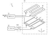
- FIG. 1 is a diagram showing a schematic configuration of a heating system 10 according to the present embodiment.
- the heating system 10 is a system for warming an occupant seated on a vehicle seat, for example.
- the heating system 10 includes a seat heater 20, a heater unit 32, a detection unit 33, and a switch SW1.
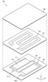
- FIG. 2 is an exploded perspective view of the seat heater 20. As shown in FIG. 2, the seat heater 20 covers the sensor electrode 25, the two heater electrodes 21 and 22, the heating elements 23 and 24 formed over the heater electrode 21 and the heater electrode 22, and the above-described parts. Insulating sheets 26, 27, and 28 are provided.
- the insulating sheets 26, 27, and 28 are, for example, sheets made of PET (polyethylene terephthalate), mylar films, and the like. Further, as the insulating sheets 26, 27, 28, sheets made of a flexible material such as polyimide, polyvinyl chloride, or silicon rubber can be used. These insulating sheets 26, 27, and 28 are shaped in a rectangular shape whose longitudinal direction is the Y-axis direction.
- the heater electrode 21 is formed on the upper surface of the insulating sheet 26. As shown in FIG. 2, the heater electrode 21 is made of silver paste or copper and is patterned in a U shape. A connection portion 21a connected to the switch SW1 is formed on the ⁇ X side of the heater electrode 21.
- the heater electrode 22 is shaped in a U shape, and a connection portion 22a connected to the switch SW1 is formed on the -X side.
- the pattern on the + Y side of the heater electrode 22 is surrounded by the heater electrode 21.
- These heater electrodes 21 and 22 can be formed on the upper surface of the insulating sheet 26 by bonding the copper foil to the upper surface of the insulating sheet 26 and then etching and patterning the copper foil.
- Each of the heating elements 23 and 24 is shaped in a rectangular shape whose longitudinal direction is the X-axis direction, and is formed adjacent to each other in the Y-axis direction. As shown in FIG. 3, each of the heating elements 23 and 24 is formed from the upper surface of the heater electrode 21 to the upper surface of the heater electrode 22.
- These heating elements 23 and 24 are formed by applying a thermal resistance paste or a carbon paste from the heater electrode 21 to the heater electrode 22 on the upper surface of the insulating sheet 26 on which the heater electrodes 21 and 22 are formed, and curing them. 26 can be formed on the upper surface.
- the sensor electrode 25 is formed to meander the upper surface of the insulating sheet 27. Similarly to the heater electrodes 21 and 22, the sensor electrode 25 is also made of copper. The sensor electrode 25 can be formed, for example, by bonding a copper foil to the upper surface of the insulating sheet 27 and then etching and patterning the copper foil.
- the insulating sheets 26 to 28 constituting the seat heater 20 are bonded to the upper surface of the insulating sheet 26 on which the heater electrodes 21 and 22 are formed by bonding the insulating sheet 27 on which the sensor electrode 25 is formed. Then, the insulating sheet 28 is bonded to the upper surface of the insulating sheet 27 to be integrated.
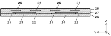
- FIG. 3 is a view showing a ZY section of the seat heater 20.
- the heater electrodes 21 and 22 and the heating elements 23 and 24 and the sensor electrode 25 are insulated by an insulating sheet 27.
- the heater electrodes 21 and 22 and the heating elements 23 and 24 are covered with an insulating sheet 26, and the sensor electrode 25 is covered with an insulating sheet 28.
- FIG. 4 is a view showing the seat 101 of the vehicle 100 together with the occupant 120 seated on the seat 101.
- the seat heater 20 configured as described above is disposed directly below the seat cover that constitutes the seating surface 101 a of the seat 101.
- the heater unit 32 is connected to the heater electrodes 21 and 22 via the switch SW1.
- the heater unit 32 supplies electric energy from a battery (not shown) mounted on the vehicle 100 to the heating elements 23 and 24 via the heater electrodes 21 and 22. Thereby, a current flows through the heating elements 23 and 24, and the heating elements 23 and 24 generate heat.
- the switch SW1 intermittently disconnects the heater unit 32 and the heater electrodes 21 and 22.
- the heater unit 32 and the heater electrodes 21 and 22 are disconnected, the heater electrodes 21 and 22 and the heating elements 23 and 24 are insulated from the vehicle 100.
- the detection unit 33 monitors the potential of the heater electrode 21 and obtains the capacitance between the sensor electrode 25 and the vehicle 100 when the heater unit 32 and the heater electrodes 21 and 22 are disconnected by the switch SW1. Based on the obtained capacitance, it is determined whether or not the occupant 120 is seated on the seat 101. Then, the detection unit 33 outputs the result of the determination to an external device, for example.
- FIG. 5 is a diagram schematically showing an electric circuit formed when the occupant 120 is not seated on the seat 101.
- the sensor electrode 25 is connected to the heater electrodes 21 and 22 via capacitors C4 and C6.
- the heater electrodes 21 and 22 are connected to the vehicle 100 via capacitors C1 and C3.
- the heat generating bodies 23 and 24 are connected to the vehicle 100 via the capacitor C2.
- FIG. 6 is an equivalent circuit of the circuit shown in FIG.
- the circuit shown in FIG. 5 can be replaced with the equivalent circuit shown in FIG.
- a resistor Ra constituting the equivalent circuit of FIG. 6 indicates a resistance between the heater electrode 21 and the heater electrode 22.
- the resistance Rb indicates the resistance of the sensor electrode 25.
- Capacitors Ca and Cb are synthesized from capacitors C1, C2, and C3.
- Capacitors Cc and Cd are synthesized from capacitors C4, C5 and C6.
- the combined capacitance C T1 between the sensor electrode 25 and the vehicle 100 is determined by capacitors Ca, Cb, Cc, and Cd.
- FIG. 7 is a diagram schematically showing an electric circuit formed when the occupant 120 is seated on the seat 101. As can be seen by comparing FIG. 7 and FIG. 5, when the occupant 120 is seated on the seat 101, a new circuit in which the occupant 120 is interposed is formed.
- the newly formed circuit includes a capacitor C7 that represents the capacitance between the sensor electrode 25 and the occupant 120, and a capacitor C8 that represents the capacitance between the occupant 120 and the vehicle 100.
- the circuit shown in FIG. 7 can be replaced with the equivalent circuit shown in FIG.
- the equivalent circuit in FIG. 8 is a circuit in which capacitors Ce, Cf, C8 and a resistor Rc are added to the equivalent circuit in FIG.
- the capacitors Ce and Cf are capacitors having a capacity that is approximately half the capacity of the capacitor C7.
- the capacitor C8 is a capacitor representing the capacitance between the occupant 120 and the vehicle 100 as described above.
- the resistance Rc represents the resistance between the occupant 120 and the vehicle 100.
- the combined capacitance C T2 of the sensor electrode 25 and the vehicle 100 when the occupant 120 is seated on the seat 101 is measured from the following equation (1). .
- C T2 C T1 + C8 ⁇ (Ce + Cf) / (Ce + Cf + C8) (1)
- the detection unit 33 detects the combined capacitance that changes as described above, and determines whether or not the occupant 120 is seated on the seat 101 based on the detection result.
- a specific configuration of the detection unit 33 will be described.
- the detection unit 33 has an AC power source 33a, a quadrature demodulator 33b, and a detector 33c.
- the AC power supply 33a converts the voltage of a battery (not shown) mounted on the vehicle 100 into an AC voltage of about 100 kHz and applies it between the sensor electrode 25 and the vehicle 100 body.
- the quadrature demodulator 33 b monitors the AC voltage V between the sensor electrode 25 and the vehicle 100 and the current i supplied to the sensor electrode 25. Then, the quadrature demodulator 33b outputs information regarding the in-phase component I of the current i with respect to the AC voltage V and information regarding the quadrature component Q of the current i with respect to the AC voltage V to the detector 33c.
- the detector 33c determines whether or not the occupant 120 is seated on the seat 101 based on the value of the in-phase component I and the value of the quadrature component Q.
- the detector 33c outputs the determined result to, for example, an external device.
- each synthesized R T resistor and total capacitance C T between the sensor electrode 25 and the vehicle 100 represented by the following formula (2) and the following equation (3).
- equation (2) the combined capacitance C T It can be seen that is equivalent to the quadrature component Q of the current i.
- the detector 33c compares the value of the orthogonal component Q with a predetermined threshold value. When the orthogonal component Q is equal to or greater than the threshold, the detector 33c determines that the occupant 120 is seated on the seat 101. On the other hand, when the orthogonal component Q is smaller than the predetermined threshold, the detector 33c determines that the occupant 120 is not seated on the seat 101.
- the capacitance between the sensor electrode 25 and the vehicle 100 is low.
- the above threshold value is determined in consideration of the increase. This threshold value is determined using a straight line indicating the IQ characteristic shown in FIG.
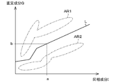
- the detector 33c determines the threshold based on the curve L that separates the area AR1 and the area AR2. For example, when the value of the in-phase component I is a, the detector 33c determines that the threshold is b.
- the detector 33c determines that the occupant 120 is seated on the seat 101 when the value of the orthogonal component Q is larger than the threshold value b. On the other hand, when the value of the orthogonal component Q is smaller than the threshold value b, the detector 33c determines that the occupant 120 is not seated on the seat 101. And the detector 33c outputs the information regarding the result of the above-mentioned discrimination to an external device, for example.
- the external device can use the determination result for, for example, control when warning the wearing of the seat belt or deploying the airbag.
- the seat heater 20 includes the film-like heater electrodes 21 and 22 and the film-like sensor electrode 25.
- the heater electrodes 21 and 22 are disconnected from the heater unit 32 and are substantially insulated from the vehicle 100. For this reason, when detecting the occupant 120, the detection unit 33 can detect the occupant 120 without being affected by the heater electrodes 21 and 22. This will be specifically described below.
- the capacitance of the capacitors Cc and Cd shown in FIG. 6 or FIG. Will grow.
- the heater electrodes 21 and 22 are disconnected from the heater unit 32 when the occupant 120 is detected.
- the capacitances of the capacitors Ca and Cb shown in FIG. 8 are relatively smaller than the capacitances of the capacitors Cc and Cd.
- the capacitance C T1 between the sensor electrode 25 and the vehicle 100 when the occupant 120 is not seated on the seat 101 is also a relatively small value.
- the capacitance C T2 when the occupant 120 is seated on the seat 101 and the capacitance C T1 when the occupant 120 is not seated on the seat 101 are shown.
- the heater electrodes 21 and 22 when the heater electrodes 21 and 22 are connected to the heater unit 32, the heater electrodes 21 and 22 may be grounded to the vehicle 100 through the heater unit 32. In this case, the capacitance between the heater electrodes 21 and 22 and the vehicle 100 or between the heater electrode 21 and the sensor electrode 25 increases. Also in this case, the seat 101 is seated by taking into consideration the electrostatic capacity between the heater electrodes 21 and 22 and the occupant 120, the electrostatic capacity between the heater electrodes 21 and 22 and the sensor electrode 25, and the like. The occupant 120 can be detected.
- the detection unit 33 determines whether or not the heater unit 32 and the heater electrodes 21 and 22 are disconnected by monitoring the potential of the heater electrode 22. Not limited to this, the detection unit 33 may determine whether or not the heater unit 32 and the heater electrodes 21 and 22 are disconnected by monitoring the state of the switch SW1.
- the detection unit 33 monitors the potential of the heater electrode 21 to determine whether or not the heater unit 32 and the heater electrodes 21 and 22 are disconnected. Not limited to this, when the detection unit 33 detects the occupant 120, the switch SW1 may be driven to disconnect the heater unit 32 and the heater electrodes 21, 22.
- a threshold for determining whether or not the occupant 120 is seated on the seat 101 is determined based on the value of the in-phase component I output from the quadrature demodulator 33b, and based on this threshold Thus, the above determination is performed. Therefore, the occupant 120 can be detected with high accuracy.
- the seat heater 20 has the two heater electrodes 21 and 22 has been described. Not limited to this, the seat heater 20 may have three or more heater electrodes.
- both the heater electrode 21 and the heater electrode 22 are separated from the heater unit 32 by the switch SW1. Not limited to this, only one of the heater electrode 21 and the heater electrode 22 may be separated. Further, when the seat heater 20 has three or more heater electrodes, only a part of the heater electrodes may be separated from the heater unit 32.
- the heater electrodes 21 and 22 may be separated from the heater unit 32 for about 0.1 second. For this reason, the function which warms the passenger
- the heating system 10A according to the present embodiment is different from the first embodiment in that an AC voltage is applied to both the sensor electrode 25 and the heater electrodes 21 and 22 when attempting to detect the occupant 120.
- FIG. 11 is a block diagram of the heating system 10A according to the present embodiment. As shown in FIG. 11, the heating system 10A includes a switch SW2 and a detection unit 33A.
- the switch SW2 alternately connects the heater electrodes 21 and 22 of the seat heater 20 to the heater unit 32 and the detection unit 33A.
- the detection unit 33A constituting the heating system 10A includes AC power supplies 34A and 34B, an orthogonal demodulator 33b, and a detector 33c.
- the AC power supply 34A applies an AC voltage V1 having an amplitude v to both ends of the sensor electrode 25. Further, the AC power supply 34B, when the heater electrodes 21 and 22 are connected to the detection unit 33A by the switch SW2, supplies an AC voltage V2 having an amplitude v that is 180 degrees different from the AC voltage V1 to the heater electrodes 21 and 22. Apply.
- FIG. 12 is an equivalent circuit of a circuit formed when the heater electrodes 21 and 22 are connected to the detection unit 33A by the switch SW2.
- the phase of the AC voltage applied by the AC power supplies 34A and 34B differs by 180 degrees. For this reason, the potential difference between the points P1 and P2 at both ends of the capacitor Cc and the potential difference between the points P3 and P4 at both ends of the capacitor Cd in FIG.
- the value of the current i1 supplied to the sensor electrode 25 from the AC power supply 34A increases. Therefore, the values of the in-phase component I and the quadrature component Q of the current i1 with respect to the AC voltage V1 output from the quadrature demodulator 33b are relatively large.
- the insulating sheet 27 interposed between the sensor electrode 25 and the heater electrodes 21 and 22 described above is compressed and deformed according to the weight of the occupant 120 seated on the seat 101. Therefore, by detecting the change of the orthogonal component Q, it is possible to detect the mass of the object placed on the seat 101, such as the weight of the occupant 120. In this case, by using a material that can be easily elastically deformed as the insulating sheet 27, it is possible to improve the detection accuracy such as the weight of the occupant 120.
- the phases of the AC voltages V1 and V2 applied by the AC power supplies 34A and 34B are shifted from each other by 180 degrees.
- the detection unit 33 can detect the occupant 120 seated on the seat 101 even when the phases and amplitudes of the AC voltages V1 and V2 applied by the AC power supplies 34A and 34B are equal.
- the potential of the sensor electrode 25 is equal to the potential of the heater electrodes 21 and 22. That is, the potentials at points P1 to P4 in FIG. 12 are equal.
- the detection unit 33 can detect the occupant 120 without being affected by the heater electrodes 21 and 22.
- the detection unit 33 has only the electrostatic capacitance between the sensor electrode 25 and the occupant 120 indicated by the capacitors Ce and Cf, and the electrostatic capacitance between the occupant 120 and the vehicle 100 indicated by the capacitor C8. Will be detected. Therefore, the detection unit 33 can detect the occupant 120 with high accuracy.
- the present embodiment it is possible to adjust the detection sensitivity of the occupant 120 by the sensor electrode 25 by changing the phase of the AC voltages V1 and V2 applied by the AC power supplies 34A and 34B. .
- the occupant 120 can be accurately detected without being affected by the heater electrodes 21 and 22.
- the occupant 120 is detected based on the current i1 between the AC power supply 34A and the sensor electrode 25. For example, by detecting the current i2 between the AC power supply 34B and the heater electrodes 21 and 22, similarly, between the heater electrodes 21 and 22 indicated by the capacitors Ca and Cb and the vehicle 100, for example. Capacitance can also be detected.
- the seat 101 is deformed when the occupant 120 is seated, and the electrostatic capacity includes the distance between the heater electrodes 21 and 22 and the vehicle 100, the distance between the heater electrodes 21 and 22 and components provided on the vehicle 100, and the like. Increased due to shrinkage. For this reason, the weight of the occupant 120 seated on the seat 101 can be detected by detecting a change in capacitance between the heater electrodes 21 and 22 and the vehicle 100. In this case, the sensor electrode 25 acts as a shield for the heater electrodes 21 and 22. Therefore, the weight of the occupant 120 seated on the seat 101 can be detected via the heater electrodes 21 and 22 without being affected by the capacitance between the occupant 120 and the sensor electrode 25.
- the occupant 120 seated on the seat 101 and the spatial size of the object placed on the seat 101 are detected via the sensor electrode 25, and the heater electrode 21 is detected. , 22, the weight of the occupant 120 seated on the seat 101 and the object placed on the seat 101 can be detected.
- the heater electrodes 21 and 22 are used as shields, it is desirable that the heater electrodes 21 and 22 have an area equal to or larger than that of the sensor electrode 25 and that both electrodes overlap. Further, when the sensor electrode 25 is used as a shield, it is desirable that the sensor electrode 25 has an area equal to or larger than that of the heater electrodes 21 and 22 and both electrodes overlap. In this case, when both electrodes have the same shape, the shielding efficiency is the highest.
- the heater electrodes 21 and 22 may be used as a shield.
- some of the heater electrodes may be used as a shield.
- phase difference between the phase of the voltage applied by the AC power supply 34A and the phase of the voltage applied by the AC power supply 34B is 180 degrees.
- the phase difference may not necessarily be 180 degrees.
- the sensor electrode 25 is disposed at a position close to the occupant 120, and the heater electrodes 21 and 22 are disposed at positions far from the occupant 120.
- the heater electrodes 21 and 22 may be disposed at a position close to the occupant 120, and the sensor electrode 25 may be disposed at a position far from the occupant 120. In this case, the occupant 120 can be efficiently warmed.
- the quadrature demodulator 33b and the detector 33c may be connected to any of the AC power supplies 34A and 34B. Further, the quadrature demodulator 33b and the detector 33c are connected to both the AC power supplies 34A and 34B, and the values of the in-phase component I and the quadrature component Q are switched by switching the output voltage values and phases of the AC power supplies 34A and 34B. It is good also as seeking.
- the heater electrodes 21 and 22 and the sensor electrode 25 of the seat heater 20 are formed on separate insulating sheets. Not limited to this, the heater electrodes 21 and 22 and the sensor electrode 25 may be formed on the same insulating sheet. Thereby, the structure of the seat heater 20 can be simplified.
- FIG. 13 is a plan view of a seat heater 20A according to a modification. As shown in FIG. 13, in the seat heater 20 ⁇ / b> A, the heater electrodes 21 and 22, the heating elements 23 and 24, and the sensor electrode 25 are formed between the laminated insulating sheets 26 and 28.
- the sensor electrode 25 is patterned so that sensor portions 25a shaped in a rectangular shape with the longitudinal direction as the X-axis direction are positioned on both sides of the heater electrodes 21 and 22 and the heating elements 23 and 24.
- Insulating sheets 26 and 28 for covering the heater electrodes 21 and 22, the heating elements 23 and 24, and the sensor electrode 25 from the upper surface side (+ Z side) and the lower surface side ( ⁇ Z side) are represented by dotted lines L 1 and L 1 shown in FIG.
- the seat heater 20 can be shaped as shown in FIG. In the seat heater 20 shown in FIG. 14, the heater electrodes 21 and 22 and the heating elements 23 and 24 are disposed on the upper surface side, and the sensor portion 25a of the sensor electrode 25 is disposed on the lower surface side.
- the seat heater 20A including the heater electrodes 21 and 22, the heating elements 23 and 24, and the sensor electrode 25 according to the present modification can also be used as the seat heater according to the first embodiment and the second embodiment.
- the heater electrodes 21 and 22, the heating elements 23 and 24, and the sensor electrode 25 can be integrally formed, so that the manufacturing cost can be reduced.
- a spacer 29 may be arranged between the heater electrodes 21 and 22 and the heating elements 23 and 24 and the sensor electrode 25. According to this, adjustment of the capacitance between the heater electrodes 21 and 22 and the sensor electrode 25 is facilitated by adjusting the thickness of the spacer 29.
- the seat heater 20A may be arranged and used such that the sensor electrode 25 is located on the upper surface side and the heater electrodes 21 and 22 are located on the lower surface side.
- information related to the determination result by the detection unit 33 is output to the external device.
- the present invention is not limited to this, and information related to the determination result by the detection unit 33 may be output to the heater unit 32. Accordingly, the heater unit 32 can stop energization of the heater electrodes 21 and 22 when the occupant 120 is not seated on the seat 101, for example. Thereby, wasteful power consumption can be suppressed.
- the heater unit 32 acquires information on the in-phase component I from the detection unit 33, and when the in-phase component I exceeds the threshold value, the heater unit 21 determines that the sheet 101 is damp and is heated. , 22 may be continued. According to this, drying of the seat 101 can be promoted, and the detection accuracy of the occupant 120 seated on the seat 101 can be improved.
- a resistance temperature detector PT for detecting the temperature of the sheet 101 may be formed on the upper surface of the insulating sheet 26 or the insulating sheet 27. Accordingly, the detection unit 33 detects the temperature of the seat 101 from the resistance value of the resistance temperature detector PT, and determines whether or not the occupant 120 is seated on the seat 101 in consideration of the detected temperature. Can be corrected.
- the temperature of the seat 101 is detected from the resistance values of the heating elements 23 and 24 obtained via the heater electrodes 21 and 22, and whether or not the occupant 120 is seated on the seat 101 in consideration of the detected temperature. It is good also as correcting the threshold value for discriminating.
- the detection unit may be configured by hardware, or may be a computer or a microcomputer including a CPU (Central Processing Unit), a main storage unit, and an auxiliary storage unit. Good.
- CPU Central Processing Unit
- main storage unit main storage unit
- auxiliary storage unit main storage unit
- the seat heater 20 is mounted on the seat 101 of the vehicle 100 .
- the seat heater 20 may be used as being attached to a seat other than the seat 101 of the vehicle 100.
- the heating system of the present invention is suitable for warming an occupant and detecting the occupant.
Landscapes
- Engineering & Computer Science (AREA)
- Aviation & Aerospace Engineering (AREA)
- Transportation (AREA)
- Mechanical Engineering (AREA)
- Seats For Vehicles (AREA)
- Air-Conditioning For Vehicles (AREA)
- Geophysics And Detection Of Objects (AREA)
Abstract
シートヒータ(20)を、フィルム状のヒータ電極(21,22)と、フィルム状のセンサ電極(25)とで構成する。そして、センサ電極(25)を用いた乗員の検出の際には、ヒータ電極(21,22)をヒータユニット(32)から切り離し、車両からほぼ絶縁された状態とする。これにより、ヒータ電極(21,22)の影響を受けることなく、シートに着座した乗員の検出を行うことが可能となる。この構成により、乗員を暖めるとともに、乗員を精度よく検出することができる。
Description
本発明は、ヒーティングシステムに関し、更に詳しくは、乗員を暖めるためのヒーティングシステムに関する。
シートベルトやエアバッグシステムなどに代表される乗員拘束システムは、装置の小型化、低コスト化が推進され、現在では、ほとんどの車種に、標準的に搭載されるに至っている。この種の乗員拘束システムは、例えば、乗員にシートベルトの着用を促すため、または乗員の有無に応じてエアバッグを制御するために、シートに着座した乗員を精度よく検出する必要がある。
一方、寒冷地で使用される車両のシートには、乗員を暖めるための発熱体が装備されることがある。車両のシートは、座面がウレタンフォーム等の熱伝導率が低い素材によって構成されるのが一般的である。このため、効率的に乗員を暖めようとすると、上述の発熱体を、シートの表面近くに配置することが必要になる。
そこで、フィルム状の発熱体とフィルム状のセンサとが張り合わされることにより形成された、2重構造のユニットが提案されている(例えば、特許文献1参照)。
しかしながら、シートに、センサ電極とともに乗員を暖めるためのヒータを配置すると、センサ電極とヒータとが電気的に結合し、センサ電極とヒータとの間の静電容量が、検出対象としての乗員とセンサ電極との間の静電容量よりも、著しく大きくなってしまうことがある。この場合には、乗員の着座の有無によって変化する静電容量の変化分が、センサ電極とグランド間の静電容量に比べて著しく小さくなるため、シートに着座する乗員の検出精度が低下することが考えられる。
本発明は、上述の事情の下になされたもので、乗員の検出精度を向上させることを目的とする。
上記目的を達成するために、本発明のヒーティングシステムは、
車両のシートに着座する乗員を暖めるためのヒーティングシステムであって、
前記シートに配置される発熱体と、
前記発熱体に接続されるヒータ電極と、
前記シートに配置されるセンサ電極と、
前記発熱体に電力を供給する供給手段と、
前記供給手段と前記ヒータ電極とを間欠的に接続する接続手段と、
前記供給手段と前記ヒータ電極とが接続されていないときに、前記センサ電極と前記車両との間のインピーダンスを測定する測定手段と、
前記測定手段によって測定される前記インピーダンスに基づいて、前記シートに着座する前記乗員を検出する検出手段と、
を備える。
車両のシートに着座する乗員を暖めるためのヒーティングシステムであって、
前記シートに配置される発熱体と、
前記発熱体に接続されるヒータ電極と、
前記シートに配置されるセンサ電極と、
前記発熱体に電力を供給する供給手段と、
前記供給手段と前記ヒータ電極とを間欠的に接続する接続手段と、
前記供給手段と前記ヒータ電極とが接続されていないときに、前記センサ電極と前記車両との間のインピーダンスを測定する測定手段と、
前記測定手段によって測定される前記インピーダンスに基づいて、前記シートに着座する前記乗員を検出する検出手段と、
を備える。
前記ヒータ電極と、前記発熱体又は前記ヒータ電極とが重なっていることとしてもよい。
前記測定手段は、前記センサ電極と前記車両との間に印加される交流電圧と、前記インピーダンスの変化に呼応して、前記センサ電極へ入力される電流又は電圧とから、前記センサ電極と前記車両との間の静電容量を、インピーダンス相関値として測定することとしてもよい。
前記測定手段は、前記交流電圧に対する前記電流の直交成分を、前記インピーダンス相関値としての前記静電容量として測定することとしてもよい。
前記測定手段は、前記交流電圧に対する前記電流の同相成分を測定し、
前記検出手段は、前記同相成分と前記直交成分との関係から規定される閾値と、前記静電容量との比較結果から、前記シートに着座する前記乗員を検出することとしてもよい。
前記検出手段は、前記同相成分と前記直交成分との関係から規定される閾値と、前記静電容量との比較結果から、前記シートに着座する前記乗員を検出することとしてもよい。
前記ヒーティングシステムは、前記発熱体近傍の前記シートの温度を検出する温度検出センサを備え、
前記検出手段は、前記温度検出センサによって検出された前記シートの温度、及び前記閾値と前記静電容量との比較結果に基づいて、前記乗員を検出することとしてもよい。
前記検出手段は、前記温度検出センサによって検出された前記シートの温度、及び前記閾値と前記静電容量との比較結果に基づいて、前記乗員を検出することとしてもよい。
前記接続手段は、前記ヒータ電極を、前記供給手段と、前記ヒータ電極に電圧を印加する電源とに交互に接続することとしてもよい。
前記電源は、前記センサ電極に印加される電圧と同相の電圧を印加することとしてもよい。
前記電源は、前記センサ電極に印加される電圧と、位相が異なる電圧を印加することとしてもよい。
本発明によれば、乗員の検出が行われる際に、乗員を暖めるためのヒータ電極を電源から切り離すことができる。このため、ヒータ電極及び発熱体をグランドから絶縁することができ、結果的にヒータ電極等の影響を受けることなく、乗員を精度よく検出することができる。
《第1の実施形態》
以下、本発明の第1の実施形態を、図面を参照しつつ説明する。図1は本実施形態に係るヒーティングシステム10の概略的な構成を示す図である。ヒーティングシステム10は、例えば車両のシートに着座する乗員を暖めるためのシステムである。このヒーティングシステム10は、図1に示されるように、シートヒータ20、ヒータユニット32、検出ユニット33、及びスイッチSW1を有している。
以下、本発明の第1の実施形態を、図面を参照しつつ説明する。図1は本実施形態に係るヒーティングシステム10の概略的な構成を示す図である。ヒーティングシステム10は、例えば車両のシートに着座する乗員を暖めるためのシステムである。このヒーティングシステム10は、図1に示されるように、シートヒータ20、ヒータユニット32、検出ユニット33、及びスイッチSW1を有している。
図2は、シートヒータ20の展開斜視図である。図2に示されるように、シートヒータ20は、センサ電極25と、2つのヒータ電極21,22と、ヒータ電極21とヒータ電極22とにわたって形成された発熱体23,24と、上記各部を被覆する絶縁シート26,27,28とを有している。
絶縁シート26,27,28は、例えばPET(ポリエチレンテフタレート)を素材とするシートや、マイラーフィルム等である。また、絶縁シート26,27,28として、ポリイミド、ポリ塩化ビニル、或いはシリコンゴム等の柔軟性のある素材からなるシートを用いることもできる。これらの絶縁シート26,27,28は、長手方向をY軸方向とする長方形状に整形されている。
ヒータ電極21は、絶縁シート26の上面に形成されている。図2に示されるように、このヒータ電極21は、銀ペースト或いは銅を素材とし、U字状にパターニングされている。そして、ヒータ電極21の-X側には、スイッチSW1と接続される接続部21aが形成されている。
ヒータ電極21と同様に、ヒータ電極22はU字状に整形され、-X側にスイッチSW1と接続される接続部22aが形成されている。このヒータ電極22の+Y側のパターンは、ヒータ電極21によって囲まれた状態になっている。
これらのヒータ電極21,22は、絶縁シート26の上面に銅箔を接着した後に、この銅箔をエッチングしてパターニングすることによって、絶縁シート26の上面に形成されることができる。
発熱体23,24それぞれは、長手方向をX軸方向とする長方形状に整形され、Y軸方向に相互に隣接して形成されている。図3に示されるように発熱体23,24それぞれは、ヒータ電極21の上面からヒータ電極22の上面にわたって形成されている。
これらの発熱体23,24は、ヒータ電極21,22が形成された絶縁シート26の上面に、ヒータ電極21からヒータ電極22にわたって温感抵抗ペースト或いはカーボンペーストを塗布し硬化させることで、絶縁シート26の上面に形成することができる。
センサ電極25は、絶縁シート27の上面を蛇行するように形成されている。センサ電極25も、ヒータ電極21,22と同様に、銅を素材とする。このセンサ電極25は、例えば絶縁シート27の上面に銅箔を接着した後に、この銅箔をエッチングしてパターニングすることによって、形成することができる。
図2を参照するとわかるように、シートヒータ20を構成する絶縁シート26~28は、ヒータ電極21,22が形成された絶縁シート26の上面に、センサ電極25が形成された絶縁シート27を接着し、絶縁シート27の上面に絶縁シート28を接着することで一体化される。
図3は、シートヒータ20のZY断面を示す図である。図3に示されるように、ヒータ電極21,22及び発熱体23,24と、センサ電極25とは、絶縁シート27によって絶縁される。また、ヒータ電極21,22及び発熱体23,24は、絶縁シート26によって被覆され、センサ電極25は、絶縁シート28によって被覆された状態となっている。
図4は、車両100のシート101を、当該シート101に着座する乗員120とともに示す図である。図4に示されるように、上述のように構成されたシートヒータ20は、シート101の座面101aを構成するシートカバーの直下に配置される。
図1に戻り、ヒータユニット32は、スイッチSW1を介して、ヒータ電極21,22に接続されている。このヒータユニット32は、車両100に搭載された不図示のバッテリからの電気エネルギーを、ヒータ電極21,22を介して発熱体23,24に供給する。これにより、発熱体23,24に電流が流れ、発熱体23,24が発熱する。
スイッチSW1は、間欠的にヒータユニット32とヒータ電極21,22とを切り離す。ヒータユニット32とヒータ電極21,22とが切り離されたときには、ヒータ電極21,22及び発熱体23,24は、車両100から絶縁された状態となる。
検出ユニット33は、ヒータ電極21の電位を監視して、スイッチSW1によってヒータユニット32とヒータ電極21,22とが切り離されたときに、センサ電極25と車両100との間の静電容量を求め、求めた静電容量に基づいて、シート101に乗員120が着座しているか否かを判別する。そして、検出ユニット33は、判別断した結果を例えば外部装置へ出力する。
図5は、シート101に乗員120が着座していないときに形成される電気回路を模式的に示す図である。シート101に乗員が着座していないときに形成される電気回路では、図5に示されるように、センサ電極25は、コンデンサC4,C6を介してヒータ電極21,22に接続され、コンデンサC5を介して発熱体23,24に接続される。ヒータ電極21,22は、コンデンサC1,C3を介して車両100に接続される。また、発熱体23,24は、コンデンサC2を介して、車両100に接続される。
図6は、図5に示される回路の等価回路である。図5に示される回路は、図6に示される等価回路に置き換えることができる。図6の等価回路を構成する抵抗Raは、ヒータ電極21とヒータ電極22との間の抵抗等を示す。そして、抵抗Rbは、センサ電極25の抵抗を示す。また、コンデンサCa,Cbは、コンデンサC1,C2,C3が合成されたものである。また、コンデンサCc,Cdは、コンデンサC4,C5,C6が合成されたものである。
図6の等価回路を参照するとわかるように、センサ電極25と車両100との間の合成静電容量CT1は、コンデンサCa,Cb,Cc,Cdによって決定される。
図7は、シート101に乗員120が着座しているときに形成される電気回路を模式的に示す図である。図7と図5を比較するとわかるように、シート101に乗員120が着座すると、乗員120が介在する新たな回路が形成される。この新たに形成された回路は、センサ電極25と乗員120との間の静電容量を表すコンデンサC7と、乗員120と車両100との間の静電容量を表すコンデンサC8とを含んで構成される。
図7に示される回路は、図8に示される等価回路に置き換えることができる。図8の等価回路は、図6の等価回路に、コンデンサCe,Cf,C8、及び抵抗Rcを付加した回路である。なお、コンデンサCe,Cfは、コンデンサC7の容量の約半分の容量をもつコンデンサである。また、コンデンサC8は、上述の通り、乗員120と車両100との間の静電容量を表すコンデンサである。また、抵抗Rcは、乗員120と車両100との間の抵抗を表す。
図8の等価回路を参照するとわかるように、シート101に乗員120が着座しているときの、センサ電極25と車両100との合成静電容量CT2は、次式(1)から測定される。
CT2=CT1+C8・(Ce+Cf)/(Ce+Cf+C8) …(1)
上記式(1)からわかるように、シート101に乗員120が着座すると、センサ電極25と車両100との間の合成静電容量の値が、コンデンサ、Ce,Cf,C8に起因する静電容量の分だけ増加する。検出ユニット33は、上述のように変化する合成静電容量を検出し、検出した結果に基づいて、シート101に乗員120が着座しているか否かを判別する。以下、検出ユニット33の具体的な構成について説明する。
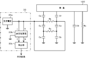
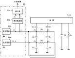
図8に示されるように、検出ユニット33は、交流電源33a、直交復調器33b、及び検出器33cを有している。
交流電源33aは、車両100に搭載された不図示のバッテリの電圧を、100kHz程度の交流電圧に変換し、センサ電極25と車両100のボディの間に印加する。
直交復調器33bは、センサ電極25と車両100との間の交流電圧Vと、センサ電極25に供給される電流iとをモニタする。そして、直交復調器33bは、交流電圧Vに対する電流iの同相成分Iと、交流電圧Vに対する電流iの直交成分Qに関する情報を、検出器33cに出力する。
検出器33cは、同相成分Iの値と直交成分Qの値とに基づいて、シート101に乗員120が着座しているか否かを判別する。そして、検出器33cは、判別した結果を例えば外部装置等へ出力する。
図6及び図8に示される電気回路は、図9に示される回路として考えることができる。この場合、センサ電極25と車両100との間の合成抵抗RT及び合成静電容量CTそれぞれは、次式(2)及び次式(3)で示される。次式(2)によれば、合成静電容量CTは電流iの直交成分Qと等価であることがわかる。
CT=Q …(2)
RT=1/I …(3)
RT=1/I …(3)
そこで、検出器33cは、例えば、直交成分Qの値と所定の閾値とを比較する。そして、直交成分Qが閾値以上である場合には、検出器33cは、シート101に乗員120が着座していると判別する。一方、直交成分Qが所定の閾値より小さい場合には、検出器33cはシート101に乗員120が着座していないと判別する。
また、本実施形態では、シート101の座面101aが濡れている場合や、シート101を構成する素材が湿り気を帯びている場合には、センサ電極25と車両100との間の静電容量が増加することを考慮して、上述の閾値を決定する。この閾値の決定には、図10に示されるIQ特性を示す直線を用いる。
図10の領域AR1は、シート101に乗員120が着座しているときの直交成分Qと同相成分Iとによって規定される点が存在する領域を示している。また、領域AR2は、シート101に乗員120が着座していないときの直交成分Qと同相成分Iとによって規定される点が存在する領域を示している。検出器33cは、閾値を、領域AR1と領域AR2とを区分する曲線Lに基づいて決定する。例えば、検出器33cは、同相成分Iの値がaである場合は、閾値をbと決定する。
そして、検出器33cは、直交成分Qの値が閾値bより大きい場合に、シート101に乗員120が着座していると判別する。一方、直交成分Qの値が閾値bより小さい場合は、検出器33cは、シート101に乗員120が着座していないと判別する。そして、検出器33cは、上述の判別の結果に関する情報を例えば外部装置へ出力する。
外部装置は、判別の結果を、例えばシートベルトの着用を警告する際や、エアバッグを展開する際の制御等に用いることができる。
以上説明したように、本実施形態に係るシートヒータ20は、フィルム状のヒータ電極21,22と、フィルム状のセンサ電極25を有している。そして、センサ電極25を用いた乗員120の検出の際には、ヒータ電極21,22がヒータユニット32から切り離され、車両100からほぼ絶縁された状態となる。このため、乗員120の検出を行う際に、検出ユニット33は、ヒータ電極21,22の影響を受けることなく、乗員120の検出を行うことが可能となる。以下、具体的に説明する。
図3に示されるように、センサ電極25とヒータ電極21,22とは、絶縁シート27の厚み分しか離間していないため、例えば図6或いは図8に示されるコンデンサCc,Cdの静電容量は大きくなる。本実施形態では、乗員120の検出の際にはヒータ電極21,22が、ヒータユニット32から切り離される。このため、例えば図8に示されるコンデンサCa,Cbの静電容量は、コンデンサCc,Cdの静電容量に比べて比較的小さくなる。また、乗員120がシート101に着座していないときの、センサ電極25と車両100との間の静電容量CT1も、比較的小さな値となる。このため、式(1)を参照するとわかるように、シート101に乗員120が着座しているときの静電容量CT2と、シート101に乗員120が着座していないときの静電容量CT1との差分(=C8・(Ce+Cf)/(Ce+Cf+C8))が、静電容量CT1に比べて大きくなる。これにより、検出ユニット33は、ヒータ電極21,22の影響をほとんど受けることなく、乗員120の検出を行うことが可能となる。
なお、ヒータ電極21,22がヒータユニット32に接続されている場合には、ヒータ電極21,22が、ヒータユニット32を介して車両100にアースされることが考えられる。この場合は、ヒータ電極21,22と車両100、或いはヒータ電極21とセンサ電極25との間の静電容量が大きくなる。この場合においても、ヒータ電極21,22と乗員120との間の静電容量や、ヒータ電極21,22とセンサ電極25との間の静電容量等を考慮することで、シート101に着座する乗員120を検出することができる。
なお、本実施形態では、検出ユニット33は、ヒータ電極22の電位を監視することによって、ヒータユニット32とヒータ電極21,22とが切り離されているか否かを判別した。これに限らず、検出ユニット33は、スイッチSW1の状態を監視することによって、ヒータユニット32とヒータ電極21,22とが切り離されているか否かを判別することとしてもよい。
また、本実施形態では、検出ユニット33は、ヒータ電極21の電位を監視して、ヒータユニット32とヒータ電極21,22とが切り離されているか否かを判別した。これに限らず、検出ユニット33が乗員120の検出を行う際に、スイッチSW1を駆動して、ヒータユニット32とヒータ電極21,22とを切り離すこととしてもよい。
また、本実施形態では、直交復調器33bから出力される同相成分Iの値に基づいて、シート101に乗員120が着座しているか否かを判別するための閾値が決定され、この閾値に基づいて、上記判別が行われる。したがって、乗員120を精度良く検出することができる。
また、本実施形態では、シートヒータ20が、2系統のヒータ電極21,22を有している場合について説明した。これに限らず、シートヒータ20は、3系統以上のヒータ電極を有していてもよい。
また、本実施形態では、スイッチSW1によって、ヒータ電極21と、ヒータ電極22の双方を、ヒータユニット32から切り離すこととした。これに限らず、ヒータ電極21及びヒータ電極22のうちのいずれか一方のみを切り離すこととしてもよい。また、シートヒータ20が、3系統以上のヒータ電極を有している場合には、一部のヒータ電極のみを、ヒータユニット32から切り離すこととしてもよい。
また、乗員120の検出の際には、約0.1秒程度、ヒータ電極21,22を、ヒータユニット32から切り離せばよい。このため、乗員120を暖める機能が害されることはない。
《第2の実施形態》
次に本発明の第2の実施形態に係るヒーティングシステムについて説明する。本実施形態に係るヒーティングシステム10Aは、乗員120の検出を試みる際に、センサ電極25及びヒータ電極21,22の双方に交流電圧を印加する点で、第1の実施形態と異なる。
次に本発明の第2の実施形態に係るヒーティングシステムについて説明する。本実施形態に係るヒーティングシステム10Aは、乗員120の検出を試みる際に、センサ電極25及びヒータ電極21,22の双方に交流電圧を印加する点で、第1の実施形態と異なる。
図11は、本実施形態に係るヒーティングシステム10Aのブロック図である。図11に示されるように、ヒーティングシステム10Aは、スイッチSW2と、検出ユニット33Aを有している。
スイッチSW2は、シートヒータ20のヒータ電極21,22それぞれを、ヒータユニット32と検出ユニット33Aに交互に接続する。
ヒーティングシステム10Aを構成する検出ユニット33Aは、交流電源34A,34B、直交復調器33b、及び検出器33cを有している。
交流電源34Aは、振幅vの交流電圧V1をセンサ電極25の両端へ印加する。また、交流電源34Bは、スイッチSW2によって、ヒータ電極21,22が検出ユニット33Aに接続されたときに、周期が交流電圧V1と180度異なる振幅vの交流電圧V2を、ヒータ電極21,22へ印加する。
例えば図12は、スイッチSW2によって、ヒータ電極21,22が、検出ユニット33Aに接続されたときに形成される回路の等価回路である。本実施形態では、交流電源34A,34Bによって印加される交流電圧の位相が180度異なっている。このため、図12におけるコンデンサCcの両端の点P1と点P2との間の電位差と、コンデンサCdの両端の点P3と点P4との間の電位差が最大2vとなる。
このため、交流電源34Aから、センサ電極25に供給される電流i1の値が大きくなる。したがって、直交復調器33bから出力される、交流電圧V1に対する電流i1の同相成分Iと、直交成分Qの値が相対的に大きくなる。
また、コンデンサCcとコンデンサCdとの間の電位差が大きくなるので、センサ電極25と車両100との間の静電容量の電流のうち、コンデンサCc,Cdに起因する電流成分が支配的になる。この場合、直交成分Qの変化を検出することでコンデンサCc,Cdの静電容量の変化を検出することが可能となる。
例えば、上述したセンサ電極25とヒータ電極21,22の間に介在する絶縁シート27は、シート101に着座する乗員120の体重に応じて圧縮変形する。したがって、直交成分Qの変化を検出することで、乗員120の体重など、シート101に載置される物体の質量等を検出することが可能となる。この場合、絶縁シート27として、弾性変形が容易な材質を用いることで、乗員120の体重などの検出精度を向上させることができる。
また、本実施形態では、交流電源34A,34Bによって印加される交流電圧V1,V2それぞれの位相は相互に180度ずれている。これに限らず、交流電源34A,34Bによって印加される交流電圧V1,V2の位相、振幅が等しい場合にも、検出ユニット33は、シート101に着座する乗員120を検出することができる。
この場合には、センサ電極25の電位とヒータ電極21,22の電位とが等しくなる。つまり、図12における点P1~点P4の電位が等しくなる。このときは、コンデンサCc,Cdの両端に電位差が生じないため、センサ電極25を用いて乗員120の検出を行う際には、ヒータ電極21,22の存在を考慮する必要がなくなる。つまり、検出ユニット33は、ヒータ電極21,22の影響を受けることなく、乗員120の検出を行うことが可能となる。
また、この場合には、コンデンサCa,Cbで示される、ヒータ電極21,22と車両100との間の静電容量が、センサ電極25を介して検出されることがなくなる。すなわち、ヒータ電極21,22と車両100との間の静電容量が、ヒータ電極21,22によってシールドされた状態となる。このため、検出ユニット33は、コンデンサCe,Cfによって示される、センサ電極25と乗員120との間の静電容量と、コンデンサC8によって示される、乗員120と車両100との間の静電容量のみを検出することになる。したがって、検出ユニット33は、精度よく乗員120の検出を行うことができる。
以上説明したように、本実施形態では、交流電源34A,34Bによって印加される交流電圧V1,V2の位相を変化させることで、センサ電極25による乗員120の検出感度を調整することが可能となる。また、ヒータ電極21,22の影響を受けることなく、乗員120を精度よく検出することが可能となる。
なお、本実施形態では、交流電源34Aとセンサ電極25との間の電流i1に基づいて、乗員120の検出を行った。これに限らず、例えば、交流電源34Bとヒータ電極21,22との間の電流i2を検出することで、同様に、コンデンサCa,Cbで示されるヒータ電極21,22と車両100との間の静電容量を検出することもできる。
この静電容量は、例えば乗員120が着座することでシート101が変形し、ヒータ電極21,22と車両100の距離や、ヒータ電極21,22と車両100に設けられた部品との距離などが縮まることに起因して増加する。このため、ヒータ電極21,22と車両100との間の静電容量の変化を検出することで、シート101に着座した乗員120の体重などを検出することができる。この場合には、センサ電極25がヒータ電極21,22に対するシールドとして作用する。したがって、乗員120とセンサ電極25との間の静電容量の影響を受けることなく、ヒータ電極21,22を介して、シート101に着座した乗員120の体重などを検出することができる。
以上のように電流i2を検出することによって、センサ電極25を介して、シート101に着座する乗員120や、シート101に載置された物体の空間的な大きさを検出するとともに、ヒータ電極21,22を介して、シート101に着座する乗員120や、シート101に載置された物体の重量を検出することが可能となる。
また、ヒータ電極21,22をシールドとして用いる場合は、ヒータ電極21,22は、センサ電極25と同等以上の面積を有し、双方の電極が重なっていることが望ましい。また、センサ電極25をシールドとして用いる場合は、センサ電極25が、ヒータ電極21,22と同等以上の面積を有し、双方の電極が重なっていることが望ましい。この場合、双方の電極の形状が等しいとき、シールド効率が最も高い状態となる。
また、ヒータ電極21,22のいずれか一方のみを、シールドとして用いてもよい。また、シートヒータ20が、3系統以上のヒータ電極を有している場合には、一部のヒータ電極をシールドとして用いることとしてもよい。
また、本実施形態では、交流電源34Aによって印加される電圧の位相と、交流電源34Bによって印加される電圧の位相との差(位相差)が180度である場合について説明したが、双方の電圧の位相差は、必ずしも180度でなくともよい。
以上、本発明の実施形態について説明したが、本発明は上記実施形態によって限定されるものではない。例えば、本実施形態では、図3及び図4を参照するとわかるように、センサ電極25が乗員120に近い位置に配置され、ヒータ電極21,22が乗員120から遠い位置に配置されている。これに限らず、ヒータ電極21,22が、乗員120に近い位置に配置され、センサ電極25が乗員120から遠い位置に配置されていてもよい。この場合には、乗員120を効率よく暖めることが可能となる。
また、直交復調器33b及び検出器33cは、交流電源34A,34Bのいずれに接続されていてもよい。さらに、直交復調器33b及び検出器33cを、交流電源34A,34B双方に接続して、交流電源34A,34Bそれぞれの出力電圧の値や、位相を切り替えて、同相成分I及び直交成分Qの値を求めることとしてもよい。
また、上記実施形態では、シートヒータ20のヒータ電極21,22とセンサ電極25とが、別々の絶縁シートに形成されている場合について説明した。これに限らず、ヒータ電極21,22とセンサ電極25とは、同一の絶縁シート上に形成されていてもよい。これにより、シートヒータ20の構造を簡素化することができる。
図13は、変形例に係るシートヒータ20Aの平面図である。図13に示されるように、シートヒータ20Aでは、ヒータ電極21,22、発熱体23,24、及びセンサ電極25が、張り合わされた絶縁シート26,28の間に形成されている。
センサ電極25は、長手方向をX軸方向とする長方形状に整形されたセンサ部25aが、ヒータ電極21,22、及び発熱体23,24の両側に位置するようにパターニングされている。
ヒータ電極21,22、発熱体23,24、及びセンサ電極25を、上面側(+Z側)と下面側(-Z側)から被覆する絶縁シート26,28を、図13に示される点線L1,L2に沿って折り曲げることで、シートヒータ20を、図14に示されるように、整形することができる。図14に示されるシートヒータ20では、上面側にヒータ電極21,22と発熱体23,24が配置され、下面側に、センサ電極25のセンサ部25aが配置されている。
本変形例に係るヒータ電極21,22、発熱体23,24、及びセンサ電極25からなるシートヒータ20Aも、上記第1の実施形態及び第2の実施形態に係るシートヒータとして用いることができる。このシートヒータ20Aでは、ヒータ電極21,22、発熱体23,24、及びセンサ電極25を一体的に形成することができるので、製造コストを低減することができる。
また、図14に示されるように、ヒータ電極21,22、及び発熱体23,24と、センサ電極25との間にスペーサ29を配置することとしてもよい。これによれば、スペーサ29の厚みを調整することで、ヒータ電極21,22とセンサ電極25の間の静電容量の調整等が容易になる。
また、シートヒータ20Aを、センサ電極25が上面側に位置し、ヒータ電極21,22が下面側に位置するように配置して、用いることとしてもよい。
また、上記実施形態では、検出ユニット33による判別の結果に関する情報が、外部装置に出力されることとした。これに限らず、検出ユニット33による判別の結果に関する情報を、ヒータユニット32に出力してもよい。これにより、ヒータユニット32は、例えば、シート101に乗員120が着座していない場合には、ヒータ電極21,22への通電を停止することができる。これにより、無駄な電力の消費を抑えることができる。
また、ヒータユニット32は、検出ユニット33から、同相成分Iに関する情報を取得し、同相成分Iが閾値を超えている場合には、シート101が湿り気を帯びていると判別して、ヒータ電極21,22の通電を継続することとしてもよい。これによれば、シート101の乾燥を促進することができ、シート101に着座する乗員120の検出精度を向上させることができる。
また、シート101の温度を検出するための測温抵抗体PTを、絶縁シート26或いは絶縁シート27の上面に形成してもよい。これにより、検出ユニット33は、測温抵抗体PTの抵抗値から、シート101の温度を検出し、検出した温度を考慮して、シート101に乗員120が着座しているか否かを判別するための閾値を補正することができる。
また、ヒータ電極21,22を介して求めた発熱体23,24の抵抗値から、シート101の温度を検出し、検出した温度を考慮して、シート101に乗員120が着座しているか否かを判別するための閾値を補正することとしてもよい。
また、上記実施形態に係る検出ユニットは、ハードウエアによって構成されていてもよいし、CPU(Central Processing Unit)、主記憶部、及び補助記憶部から構成されるコンピュータや、マイクロコンピュータであってもよい。
また、上記実施形態では、シートヒータ20が、車両100のシート101に装着されている場合について説明した。これに限らず、シートヒータ20は、車両100のシート101以外に装着することとして用いてもよい。
なお、本発明は、本発明の広義の趣旨と範囲を逸脱することなく、様々な実施形態及び変形が可能とされるものである。また、上述した実施形態は、本発明を説明するためのものであり、本発明の範囲を限定するものではない。つまり、本発明の範囲は、実施形態ではなく、特許請求の範囲によって示される。そして、特許請求の範囲内及びそれと同等の発明の意義の範囲内で施される様々な変形が本発明の範囲内とみなされる。
なお、本出願は、2010年8月5日に出願された日本国特許出願2010-176823号に基づく。本明細書中に日本国特許出願2010-176823号の明細書、特許請求の範囲、図面全体を参照として取り込むものとする。
本発明のヒーティングシステムは、乗員を暖めること、及び乗員を検出することに適している。
10,10A ヒーティングシステム
20,20A シートヒータ
21,22 ヒータ電極
21a,22a 接続部
23,24 発熱体
25 センサ電極
25a センサ部
26~28 絶縁シート
29 スペーサ
32 ヒータユニット
33,33A 検出ユニット
33a 交流電源
33b 直交復調器
33c 検出器
34A 交流電源
34B 交流電源
100 車両
101 シート
101a 座面
120 乗員
AR1,AR2 領域
C1~C8,Ca~Cf コンデンサ
L 曲線
P1~P4 点
PT 測温抵抗体
Ra~Rc 抵抗
SW1,SW2 スイッチ
20,20A シートヒータ
21,22 ヒータ電極
21a,22a 接続部
23,24 発熱体
25 センサ電極
25a センサ部
26~28 絶縁シート
29 スペーサ
32 ヒータユニット
33,33A 検出ユニット
33a 交流電源
33b 直交復調器
33c 検出器
34A 交流電源
34B 交流電源
100 車両
101 シート
101a 座面
120 乗員
AR1,AR2 領域
C1~C8,Ca~Cf コンデンサ
L 曲線
P1~P4 点
PT 測温抵抗体
Ra~Rc 抵抗
SW1,SW2 スイッチ
Claims (9)
- 車両のシートに着座する乗員を暖めるためのヒーティングシステムであって、
前記シートに配置される発熱体と、
前記発熱体に接続されるヒータ電極と、
前記シートに配置されるセンサ電極と、
前記発熱体に電力を供給する供給手段と、
前記供給手段と前記ヒータ電極とを間欠的に接続する接続手段と、
前記供給手段と前記ヒータ電極とが接続されていないときに、前記センサ電極と前記車両との間のインピーダンスを測定する測定手段と、
前記測定手段によって測定される前記インピーダンスに基づいて、前記シートに着座する前記乗員を検出する検出手段と、
を備えるヒーティングシステム。 - 前記ヒータ電極と、前記発熱体又は前記ヒータ電極とが重なっている請求項1に記載のヒーティングシステム。
- 前記測定手段は、前記センサ電極と前記車両との間に印加される交流電圧と、前記インピーダンスの変化に呼応して、前記センサ電極へ入力される電流又は電圧とから、前記センサ電極と前記車両との間の静電容量を、インピーダンス相関値として測定する請求項1又は2に記載のヒーティングシステム。
- 前記測定手段は、前記交流電圧に対する前記電流の直交成分を、前記インピーダンス相関値としての前記静電容量として測定する請求項3に記載のヒーティングシステム。
- 前記測定手段は、前記交流電圧に対する前記電流の同相成分を測定し、
前記検出手段は、前記同相成分と前記直交成分との関係から規定される閾値と、前記静電容量との比較結果から、前記シートに着座する前記乗員を検出する請求項4に記載のヒーティングシステム。 - 前記発熱体近傍の前記シートの温度を検出する温度検出センサを備え、
前記検出手段は、前記温度検出センサによって検出された前記シートの温度、及び前記閾値と前記静電容量との比較結果に基づいて、前記乗員を検出する請求項1に記載のヒーティングシステム。 - 前記接続手段は、前記ヒータ電極を、前記供給手段と、前記ヒータ電極に電圧を印加する電源とに交互に接続する請求項1に記載のヒーティングシステム。
- 前記電源は、前記センサ電極に印加される電圧と同相の電圧を印加する請求項7に記載のヒーティングシステム。
- 前記電源は、前記センサ電極に印加される電圧と、位相が異なる電圧を印加する請求項7に記載のヒーティングシステム。
Priority Applications (1)
| Application Number | Priority Date | Filing Date | Title |
|---|---|---|---|
| US13/814,480 US9067518B2 (en) | 2010-08-05 | 2011-07-27 | Heating system |
Applications Claiming Priority (2)
| Application Number | Priority Date | Filing Date | Title |
|---|---|---|---|
| JP2010176823A JP5555942B2 (ja) | 2010-08-05 | 2010-08-05 | ヒーティングシステム |
| JP2010-176823 | 2010-08-05 |
Publications (1)
| Publication Number | Publication Date |
|---|---|
| WO2012017902A1 true WO2012017902A1 (ja) | 2012-02-09 |
Family
ID=45559403
Family Applications (1)
| Application Number | Title | Priority Date | Filing Date |
|---|---|---|---|
| PCT/JP2011/067169 Ceased WO2012017902A1 (ja) | 2010-08-05 | 2011-07-27 | ヒーティングシステム |
Country Status (3)
| Country | Link |
|---|---|
| US (1) | US9067518B2 (ja) |
| JP (1) | JP5555942B2 (ja) |
| WO (1) | WO2012017902A1 (ja) |
Cited By (2)
| Publication number | Priority date | Publication date | Assignee | Title |
|---|---|---|---|---|
| JP2014151753A (ja) * | 2013-02-07 | 2014-08-25 | Autoliv Development Ab | ヒータ付シートベルト装置 |
| CN104786885A (zh) * | 2015-05-14 | 2015-07-22 | 东风李尔汽车座椅有限公司 | 汽车座椅加热垫 |
Families Citing this family (13)
| Publication number | Priority date | Publication date | Assignee | Title |
|---|---|---|---|---|
| JP5895753B2 (ja) * | 2012-07-16 | 2016-03-30 | 株式会社デンソー | 空調装置用送風ユニット |
| CN105144838B (zh) | 2013-05-15 | 2017-09-12 | 捷温加拿大有限公司 | 具有感测能力的传导性加热器 |
| KR101799842B1 (ko) | 2013-10-11 | 2017-11-21 | 젠썸 캐나다 유엘씨 | 히팅장치에 의한 탑승자 감지 |
| US9815488B2 (en) | 2014-05-13 | 2017-11-14 | Gentherm Gmbh | Temperature control device for a steering device |
| JP6358567B2 (ja) * | 2016-01-26 | 2018-07-18 | マツダ株式会社 | 静電センサを用いたシートヒータ制御装置 |
| DE102016108632B3 (de) * | 2016-05-10 | 2017-08-24 | Faurecia Autositze Gmbh | Bezugmaterial, insbesondere Sitzbezugmaterial, und Fahrzeuginnenraumanordnung, insbesondere Sitzanordnung |
| US10442328B2 (en) * | 2016-06-21 | 2019-10-15 | Kongsberg Automotive Ab | Assembly, system, and circuit with combined heating and occupancy detecting for a vehicle seat |
| JP7135558B2 (ja) * | 2018-08-07 | 2022-09-13 | 株式会社デンソー | ヒータ装置 |
| US12029469B2 (en) * | 2018-10-25 | 2024-07-09 | Domain Surgical, Inc. | Surgical shears having ferromagnetic heater |
| LU100986B1 (en) * | 2018-11-13 | 2020-05-13 | Iee Sa | Method of Operating a Capacitive Sensing System with Heater as Guard Electrode |
| KR102199815B1 (ko) * | 2019-10-10 | 2021-01-07 | 주식회사 테라온 | 접촉식 스위치가 구비된 면상 발열 히터 |
| DE102021118901A1 (de) * | 2021-07-21 | 2023-01-26 | Huf Hülsbeck & Fürst Gmbh & Co. Kg | Verfahren und Vorrichtung zur Annäherungserfassung |
| KR102767844B1 (ko) * | 2022-12-29 | 2025-02-17 | 주식회사 테라온 | 면상 발열체 |
Citations (7)
| Publication number | Priority date | Publication date | Assignee | Title |
|---|---|---|---|---|
| JPH10199661A (ja) * | 1997-01-13 | 1998-07-31 | Riken Corp | ヒーター装置及びその製造方法 |
| JP2003231411A (ja) * | 2001-12-06 | 2003-08-19 | Denso Corp | 車両用空調装置 |
| JP2005172839A (ja) * | 2005-02-03 | 2005-06-30 | Matsushita Electric Ind Co Ltd | 温度測定システム |
| JP2008024087A (ja) * | 2006-07-19 | 2008-02-07 | Denso Corp | 車両用座席装置及びその製造方法 |
| JP2008191110A (ja) * | 2007-02-07 | 2008-08-21 | Denso Corp | 2電極型静電容量センサ、車両用乗員検出装置及び車両用乗員保護システム |
| JP2010073530A (ja) * | 2008-09-19 | 2010-04-02 | Panasonic Corp | 乗員検知用検知線付き面状発熱体 |
| JP2010070086A (ja) * | 2008-09-19 | 2010-04-02 | Panasonic Corp | 乗員検知機能付き座席 |
Family Cites Families (4)
| Publication number | Priority date | Publication date | Assignee | Title |
|---|---|---|---|---|
| JP4188680B2 (ja) * | 2000-05-26 | 2008-11-26 | オートモーティブ システムズ ラボラトリー インコーポレーテッド | 乗員センサ |
| KR100580779B1 (ko) | 2000-07-17 | 2006-05-22 | 콩스베르그 오토모티브 아베 | 차량 시트 가열 장치 |
| DE10311132A1 (de) | 2003-03-12 | 2004-09-23 | Continental Teves Ag & Co. Ohg | Verfahren und eine Einrichtung zum Ansteuern eines reversiblen Insassenschutzmittels |
| EP2085263A1 (en) | 2008-01-31 | 2009-08-05 | IEE INTERNATIONAL ELECTRONICS & ENGINEERING S.A. | Vehicle seat with capacitive occupant detection system |
-
2010
- 2010-08-05 JP JP2010176823A patent/JP5555942B2/ja not_active Expired - Fee Related
-
2011
- 2011-07-27 WO PCT/JP2011/067169 patent/WO2012017902A1/ja not_active Ceased
- 2011-07-27 US US13/814,480 patent/US9067518B2/en not_active Expired - Fee Related
Patent Citations (7)
| Publication number | Priority date | Publication date | Assignee | Title |
|---|---|---|---|---|
| JPH10199661A (ja) * | 1997-01-13 | 1998-07-31 | Riken Corp | ヒーター装置及びその製造方法 |
| JP2003231411A (ja) * | 2001-12-06 | 2003-08-19 | Denso Corp | 車両用空調装置 |
| JP2005172839A (ja) * | 2005-02-03 | 2005-06-30 | Matsushita Electric Ind Co Ltd | 温度測定システム |
| JP2008024087A (ja) * | 2006-07-19 | 2008-02-07 | Denso Corp | 車両用座席装置及びその製造方法 |
| JP2008191110A (ja) * | 2007-02-07 | 2008-08-21 | Denso Corp | 2電極型静電容量センサ、車両用乗員検出装置及び車両用乗員保護システム |
| JP2010073530A (ja) * | 2008-09-19 | 2010-04-02 | Panasonic Corp | 乗員検知用検知線付き面状発熱体 |
| JP2010070086A (ja) * | 2008-09-19 | 2010-04-02 | Panasonic Corp | 乗員検知機能付き座席 |
Cited By (2)
| Publication number | Priority date | Publication date | Assignee | Title |
|---|---|---|---|---|
| JP2014151753A (ja) * | 2013-02-07 | 2014-08-25 | Autoliv Development Ab | ヒータ付シートベルト装置 |
| CN104786885A (zh) * | 2015-05-14 | 2015-07-22 | 东风李尔汽车座椅有限公司 | 汽车座椅加热垫 |
Also Published As
| Publication number | Publication date |
|---|---|
| US9067518B2 (en) | 2015-06-30 |
| JP5555942B2 (ja) | 2014-07-23 |
| JP2012035717A (ja) | 2012-02-23 |
| US20130134745A1 (en) | 2013-05-30 |
Similar Documents
| Publication | Publication Date | Title |
|---|---|---|
| JP5555942B2 (ja) | ヒーティングシステム | |
| JP5555941B2 (ja) | ヒーティングシステム | |
| JP5549872B2 (ja) | ヒーティングシステム | |
| CN103391863B (zh) | 电容式占用者检测系统 | |
| JP4305519B2 (ja) | 2電極型静電容量センサ、車両用乗員検出装置及び車両用乗員保護システム | |
| US7575085B2 (en) | Capacitance-based sensor and occupant sensing system | |
| US7701338B2 (en) | Occupant detection system and method of determining occupant | |
| JP4721058B2 (ja) | 車両用座席装置及びその製造方法 | |
| CN103874616B (zh) | 用于机动车辆的传感器系统 | |
| US9775195B2 (en) | Capacitive sensing system | |
| JP4362786B2 (ja) | フィルム式着座検出用静電容量センサ | |
| JP2014163885A (ja) | 静電容量式乗員検知センサ | |
| JP4721059B2 (ja) | 車両用座席装置及びその製造方法 | |
| JP2000080703A (ja) | 静電容量式人体局部洗浄装置用着座センサー | |
| US20140285223A1 (en) | Capacitance type occupant detection sensor | |
| JP4324877B2 (ja) | 静電容量式乗員検知センサ | |
| JP2015152307A (ja) | 静電容量式乗員検知センサ | |
| JP6144641B2 (ja) | 静電容量式乗員検知装置 | |
| JP2013190405A (ja) | 静電容量式センサ | |
| JP2004077315A (ja) | 静電容量センサ | |
| JP6669271B2 (ja) | 輻射ヒータ装置 | |
| JP2008140680A (ja) | 面状発熱体の検査方法 | |
| JP2015168401A (ja) | 乗員検知装置および乗員検知方法 | |
| JP2012224171A (ja) | 乗員検知装置、及び乗員検知方法 |
Legal Events
| Date | Code | Title | Description |
|---|---|---|---|
| 121 | Ep: the epo has been informed by wipo that ep was designated in this application |
Ref document number: 11814529 Country of ref document: EP Kind code of ref document: A1 |
|
| NENP | Non-entry into the national phase |
Ref country code: DE |
|
| WWE | Wipo information: entry into national phase |
Ref document number: 13814480 Country of ref document: US |
|
| 122 | Ep: pct application non-entry in european phase |
Ref document number: 11814529 Country of ref document: EP Kind code of ref document: A1 |