WO2012017924A1 - Structure d'ouverture/de fermeture de porte - Google Patents
Structure d'ouverture/de fermeture de porte Download PDFInfo
- Publication number
- WO2012017924A1 WO2012017924A1 PCT/JP2011/067351 JP2011067351W WO2012017924A1 WO 2012017924 A1 WO2012017924 A1 WO 2012017924A1 JP 2011067351 W JP2011067351 W JP 2011067351W WO 2012017924 A1 WO2012017924 A1 WO 2012017924A1
- Authority
- WO
- WIPO (PCT)
- Prior art keywords
- door
- shaft member
- magnet
- closing structure
- fixed
- Prior art date
- Legal status (The legal status is an assumption and is not a legal conclusion. Google has not performed a legal analysis and makes no representation as to the accuracy of the status listed.)
- Ceased
Links
Images






Classifications
-
- E—FIXED CONSTRUCTIONS
- E05—LOCKS; KEYS; WINDOW OR DOOR FITTINGS; SAFES
- E05D—HINGES OR SUSPENSION DEVICES FOR DOORS, WINDOWS OR WINGS
- E05D7/00—Hinges or pivots of special construction
- E05D7/10—Hinges or pivots of special construction to allow easy separation or connection of the parts at the hinge axis
-
- E—FIXED CONSTRUCTIONS
- E05—LOCKS; KEYS; WINDOW OR DOOR FITTINGS; SAFES
- E05D—HINGES OR SUSPENSION DEVICES FOR DOORS, WINDOWS OR WINGS
- E05D7/00—Hinges or pivots of special construction
-
- E—FIXED CONSTRUCTIONS
- E05—LOCKS; KEYS; WINDOW OR DOOR FITTINGS; SAFES
- E05D—HINGES OR SUSPENSION DEVICES FOR DOORS, WINDOWS OR WINGS
- E05D1/00—Pinless hinges; Substitutes for hinges
- E05D1/06—Pinless hinges; Substitutes for hinges consisting of two easily-separable parts
-
- E—FIXED CONSTRUCTIONS
- E05—LOCKS; KEYS; WINDOW OR DOOR FITTINGS; SAFES
- E05D—HINGES OR SUSPENSION DEVICES FOR DOORS, WINDOWS OR WINGS
- E05D15/00—Suspension arrangements for wings
-
- E—FIXED CONSTRUCTIONS
- E05—LOCKS; KEYS; WINDOW OR DOOR FITTINGS; SAFES
- E05D—HINGES OR SUSPENSION DEVICES FOR DOORS, WINDOWS OR WINGS
- E05D7/00—Hinges or pivots of special construction
- E05D7/08—Hinges or pivots of special construction for use in suspensions comprising two spigots placed at opposite edges of the wing, especially at the top and the bottom, e.g. trunnions
- E05D7/081—Hinges or pivots of special construction for use in suspensions comprising two spigots placed at opposite edges of the wing, especially at the top and the bottom, e.g. trunnions the pivot axis of the wing being situated near one edge of the wing, especially at the top and bottom, e.g. trunnions
-
- E—FIXED CONSTRUCTIONS
- E05—LOCKS; KEYS; WINDOW OR DOOR FITTINGS; SAFES
- E05D—HINGES OR SUSPENSION DEVICES FOR DOORS, WINDOWS OR WINGS
- E05D7/00—Hinges or pivots of special construction
- E05D7/10—Hinges or pivots of special construction to allow easy separation or connection of the parts at the hinge axis
- E05D7/1005—Hinges or pivots of special construction to allow easy separation or connection of the parts at the hinge axis by axially moving free pins, balls or sockets
- E05D7/1011—Hinges or pivots of special construction to allow easy separation or connection of the parts at the hinge axis by axially moving free pins, balls or sockets biased by free springs
-
- E—FIXED CONSTRUCTIONS
- E05—LOCKS; KEYS; WINDOW OR DOOR FITTINGS; SAFES
- E05D—HINGES OR SUSPENSION DEVICES FOR DOORS, WINDOWS OR WINGS
- E05D7/00—Hinges or pivots of special construction
- E05D7/10—Hinges or pivots of special construction to allow easy separation or connection of the parts at the hinge axis
- E05D7/1044—Hinges or pivots of special construction to allow easy separation or connection of the parts at the hinge axis in an axial direction
-
- E—FIXED CONSTRUCTIONS
- E05—LOCKS; KEYS; WINDOW OR DOOR FITTINGS; SAFES
- E05D—HINGES OR SUSPENSION DEVICES FOR DOORS, WINDOWS OR WINGS
- E05D7/00—Hinges or pivots of special construction
- E05D7/10—Hinges or pivots of special construction to allow easy separation or connection of the parts at the hinge axis
- E05D7/1061—Hinges or pivots of special construction to allow easy separation or connection of the parts at the hinge axis in a radial direction
-
- E—FIXED CONSTRUCTIONS
- E06—DOORS, WINDOWS, SHUTTERS, OR ROLLER BLINDS IN GENERAL; LADDERS
- E06B—FIXED OR MOVABLE CLOSURES FOR OPENINGS IN BUILDINGS, VEHICLES, FENCES OR LIKE ENCLOSURES IN GENERAL, e.g. DOORS, WINDOWS, BLINDS, GATES
- E06B7/00—Special arrangements or measures in connection with doors or windows
- E06B7/28—Other arrangements on doors or windows, e.g. door-plates, windows adapted to carry plants, hooks for window cleaners
-
- E—FIXED CONSTRUCTIONS
- E05—LOCKS; KEYS; WINDOW OR DOOR FITTINGS; SAFES
- E05D—HINGES OR SUSPENSION DEVICES FOR DOORS, WINDOWS OR WINGS
- E05D5/00—Construction of single parts, e.g. the parts for attachment
- E05D5/10—Pins, sockets or sleeves; Removable pins
- E05D2005/102—Pins
- E05D2005/104—Pins characterised by the materials
-
- E—FIXED CONSTRUCTIONS
- E05—LOCKS; KEYS; WINDOW OR DOOR FITTINGS; SAFES
- E05D—HINGES OR SUSPENSION DEVICES FOR DOORS, WINDOWS OR WINGS
- E05D7/00—Hinges or pivots of special construction
- E05D7/10—Hinges or pivots of special construction to allow easy separation or connection of the parts at the hinge axis
- E05D7/1005—Hinges or pivots of special construction to allow easy separation or connection of the parts at the hinge axis by axially moving free pins, balls or sockets
- E05D2007/1027—Hinges or pivots of special construction to allow easy separation or connection of the parts at the hinge axis by axially moving free pins, balls or sockets by axially moving free pins
-
- E—FIXED CONSTRUCTIONS
- E05—LOCKS; KEYS; WINDOW OR DOOR FITTINGS; SAFES
- E05Y—INDEXING SCHEME ASSOCIATED WITH SUBCLASSES E05D AND E05F, RELATING TO CONSTRUCTION ELEMENTS, ELECTRIC CONTROL, POWER SUPPLY, POWER SIGNAL OR TRANSMISSION, USER INTERFACES, MOUNTING OR COUPLING, DETAILS, ACCESSORIES, AUXILIARY OPERATIONS NOT OTHERWISE PROVIDED FOR, APPLICATION THEREOF
- E05Y2201/00—Constructional elements; Accessories therefor
- E05Y2201/40—Motors; Magnets; Springs; Weights; Accessories therefor
- E05Y2201/46—Magnets
-
- E—FIXED CONSTRUCTIONS
- E05—LOCKS; KEYS; WINDOW OR DOOR FITTINGS; SAFES
- E05Y—INDEXING SCHEME ASSOCIATED WITH SUBCLASSES E05D AND E05F, RELATING TO CONSTRUCTION ELEMENTS, ELECTRIC CONTROL, POWER SUPPLY, POWER SIGNAL OR TRANSMISSION, USER INTERFACES, MOUNTING OR COUPLING, DETAILS, ACCESSORIES, AUXILIARY OPERATIONS NOT OTHERWISE PROVIDED FOR, APPLICATION THEREOF
- E05Y2201/00—Constructional elements; Accessories therefor
- E05Y2201/40—Motors; Magnets; Springs; Weights; Accessories therefor
- E05Y2201/47—Springs
- E05Y2201/474—Compression springs
-
- E—FIXED CONSTRUCTIONS
- E05—LOCKS; KEYS; WINDOW OR DOOR FITTINGS; SAFES
- E05Y—INDEXING SCHEME ASSOCIATED WITH SUBCLASSES E05D AND E05F, RELATING TO CONSTRUCTION ELEMENTS, ELECTRIC CONTROL, POWER SUPPLY, POWER SIGNAL OR TRANSMISSION, USER INTERFACES, MOUNTING OR COUPLING, DETAILS, ACCESSORIES, AUXILIARY OPERATIONS NOT OTHERWISE PROVIDED FOR, APPLICATION THEREOF
- E05Y2900/00—Application of doors, windows, wings or fittings thereof
- E05Y2900/10—Application of doors, windows, wings or fittings thereof for buildings or parts thereof
- E05Y2900/13—Type of wing
- E05Y2900/132—Doors
Definitions
- the present invention relates to a door opening / closing structure, and more particularly to an opening / closing structure of a door attached to a building, furniture, figurine or the like that opens and closes freely.
- Doors that can be freely opened and closed are widely used in buildings, furniture, figurines, and the like. Many of such door opening and closing structures can freely rotate a shaft member (convex part) and a bearing (concave part). Concave and convex engagement fixed.
- the basic structure of the door opening / closing structure of Patent Document 1 is that a bearing is provided on the door side at the center of rotation of the door and the main body side to which the door is attached, and a shaft member is rotatably engaged with both bearings. Is.
- Patent Document 2 is configured so that the hinge shaft can be moved up and down while the concave and convex engagement fixing by the hinge shaft (convex portion) and the engagement hole (concave portion) is a basic configuration, and the hinge shaft is the engagement hole.
- the hinge shaft pops out by the attractive force of the magnets provided on both the hinge shaft and the engagement hole, and a hinge is proposed in which the concave and convex engagement is fixed by the hinge shaft and the engagement hole.
- this hinge is also a technology for fixing the door to the mounting object by uneven engagement, and if it is intended to remove the door from the main body, another means for releasing the uneven engagement fixation is required, and the door can be attached and detached. Is not easy.
- the present invention has been made in view of the above-described conventional problems, and provides a door opening / closing structure in which a door can be easily attached and detached in a rotary opening / closing door fixed to a door attachment target body by a magnetic attraction force. For the purpose.
- the door opening / closing structure of the present invention is arranged so that the shaft member attached to the door side and the shaft member attached to the attachment target body side of the door face each other in at least one position of the door fixed rotatably.
- One of the two shaft members is made of a magnet, and the other is made of a magnetic material or a magnet that attracts the magnet.
- the door opening and closing structure of the present invention is arranged such that at least one end of a door that is pivotably fixed at both ends, the shaft member attached to the door side and the shaft member attached to the attachment target body side of the door face each other.
- One of the two shaft members is made of a magnet, and the other is made of a magnetic material or a magnet that attracts the magnet.
- the door is rotatably fixed to the attachment target body by a magnet attractive force, and the attachment target body is resisted against the magnet attractive force in a state where the door and the attachment target body are fixed. It is preferable that it is comprised so that attachment or detachment is possible.
- the shaft member attached to the door side is fixed to the door side
- the shaft member attached to the attachment target body side of the door is fixed to the attachment target body side
- the two shafts It is preferable that the members are arranged so as to face each other at the end faces.
- At least one of the two shaft members is attached to the door or the attachment target body so as to move along the axial direction.
- an elastic body for urging the shaft member attached to the door or the attachment target body in the direction opposite to the magnet attracting direction is provided.
- a lubricant is provided on at least one of the facing surfaces of the two shaft members.
- the door and the attachment target body can be fixed not by the concave-convex engagement fixing but by the attractive force of the magnet, and preferably only by the attractive force of the magnet. Therefore, in a state where the door and the attachment target body are fixed by the magnet's attractive force, the door can be removed against the attractive force of the magnet, and attachment / detachment is easy.
- the purchaser can easily replace the door with a door having a different design according to the room design or preference.
- the door can be exchanged for a different design, it is not necessary to manufacture the door for each design, and the manufacturer / seller can reduce the number of stocks, facilitate inventory management, and reduce costs.
- design options can be greatly increased. Furthermore, even if the door is broken, it is easy to replace it, so that the cost burden during repair can be reduced.
- the shaft member when the shaft member is attached to the door or the mounting target body so as to move along the axial direction, a gap is formed between the door and the mounting target body, and a gap is formed between the opposing shaft members.
- the movable shaft member approaches the opposite shaft member by the attractive force of the magnet according to the gap, and preferably the movable shaft member protrudes from the mounting surface. Therefore, even for structures having different dimensional accuracy, it is possible to reliably rotate and fix the door and the object to be attached by the attractive force of the magnet. Thereby, it is possible to easily apply the rotation fixing structure by the attractive force of the magnet to the furniture having a certain gap between the door and the mounting target body without requiring high dimensional accuracy. .
- this movable shaft member does not move along the axial direction for engaging and releasing the concave and convex engagement fixing, but is used for rotationally fixing by the attractive force of the magnet. It is clearly different from the shaft member. Furthermore, in a state where the door and its mounting target are fixed (the shaft member is pulled out by the magnet's attractive force and protrudes from the mounting surface of the shaft member), the door resists the magnet's attractive force. Is essentially different from the conventional shaft member configured to be movable on the premise of concavo-convex engagement and fixation.
- the movable shaft member is attached to the movable shaft member by the elastic body in a state where the door and the attachment target body are not fixed.
- the shaft member is biased to the surface side, and preferably biased in a direction that does not protrude from the mounting surface of the shaft member, so that the shaft member does not get in the way when the door is mounted.
- the shaft member moves to the opposite shaft member side and preferably protrudes from the mounting surface of the shaft member by the attractive force of the magnet against the urging force of the elastic body.
- FIG. 1 is a schematic perspective view of furniture according to a first embodiment of the present invention. It is a schematic sectional drawing of the door opening / closing structure with which the furniture of FIG. 1 was equipped. It is a schematic perspective view of the furniture by the 2nd Embodiment of this invention.
- FIG. 4 is a schematic cross-sectional view taken along the line XX of the door opening / closing structure provided in the furniture of FIG. 3. It is a schematic sectional drawing of the door opening / closing structure with which the furniture by the 3rd Embodiment of this invention was equipped, and is a figure corresponding to FIG. It is a schematic perspective view of the furniture which concerns on the door opening / closing structure by the 4th Embodiment of this invention.
- FIG. 10 is a diagram corresponding to FIG. 9, and is a schematic cross-sectional view showing a door attachment target body in a state before the door is attached.
- FIG. 1 is a schematic perspective view of the furniture according to the first embodiment of the present invention
- FIG. 2 is a schematic cross-sectional view of the door opening / closing structure provided in the furniture of FIG.
- the furniture A is a wooden structure having a box shape having a top plate 5 and a base plate 6, covered on three sides, and opened on almost the entire front surface.
- a pair of left and right doors 1a and 1b for opening and closing the opening in a double door manner is attached on both sides of the front surface of the furniture A.
- the two doors 1a and 1b are wooden rectangular plates.
- One end of the doors 1a and 1b is forward of the opening end of the front surface of the furniture A, and the upper and lower sides thereof are fixed to the top plate 5 and the base plate 6 so as to be rotatable.
- a cylindrical shaft member (hereinafter referred to as a first shaft member) 10a is embedded and fixed at the lower end of the door 1a so as to slightly protrude substantially flush with the lower surface of the door 1a.
- a columnar shaft member (hereinafter referred to as a second shaft member) 10b is almost the same as the top surface of the ground plate 6 on the top surface of the ground plate 6 that is a member on the door attachment target body side. It is embedded and fixed so that it is flush.
- the fixing is performed by fitting, pins, screws, or an adhesive.
- the first shaft member 10a is made of a magnet
- the second shaft member 10b is made of iron.
- the type of magnet is not particularly limited, but it is preferable to use a permanent magnet such as a ferrite magnet or a neodymium magnet that is easy to handle
- the second shaft member is not limited to iron, but may be a magnetic material or martensite. Ferromagnetic materials such as stainless steel can be used.
- the first shaft member 10a and the second shaft member 10b are arranged so that the lower end surface of the first shaft member 10a and the upper end surface of the second shaft member 10b, that is, the end surfaces of the shaft members 10a and 10b face each other. Both the opposing surfaces are flat surfaces, and no recess is formed. The lower surface of the top plate 5 and the upper surface of the door 1a are also flat, and no unevenness for fixing the unevenness of the door 1a is formed. Moreover, both the above-mentioned opposing surfaces are smooth surfaces. As a result, the frictional resistance due to the contact between the first shaft member 10a and the second shaft member 10b is reduced, so that the door 1a can be easily rotated and detached from the furniture A.
- FIG. 3 is a schematic perspective view of the furniture according to the second embodiment of the present invention
- FIG. 4 is a schematic cross-sectional view along the line XX of the door opening / closing structure provided in the furniture of FIG. Since the configuration of the door opening and closing structure according to the present embodiment is basically the same as that according to the first embodiment described above, the differences will be mainly described.
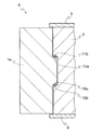
- the door 1 a according to the second embodiment has a concave end on the opening surface side of the side wall 7 of the furniture A, and the door 1 a is fixed to the notch.
- the protrusions formed at the ends are inserted, and the shaft members 10a and 11a are embedded and fixed at the lower and upper ends of the protrusions, and are located at positions corresponding to the notches of the shaft members 10a and 11a.
- the shaft member 10b, 11b is embedded and fixed, which is different from that according to the first embodiment.
- a gap is provided between the vertical surface of the door 1a and the side wall 7 and between the convex portion and the notch so that the door 1a can rotate.
- the door 1a is pivotally fixed to the side wall 7 that is the attachment target body by the magnet's attractive force, so that the door can be removed against the attractive force of the magnet.
- FIG. 5 is a schematic cross-sectional view of the door opening / closing structure provided in the furniture according to the third embodiment of the present invention, and corresponds to FIG. Since the configuration of the door opening / closing structure according to the present embodiment is basically the same as that according to the second embodiment described above, the differences will be mainly described.
- the door 1 a according to the third embodiment has a plurality (two places) of notches formed vertically on the opening surface side of the side wall 7, and the door 1 a is fixed so as to correspond to this.
- the difference from the second embodiment is that a plurality (two places) of convex portions are formed at the ends.
- the door 1a is pivotally fixed to the side wall 7 that is the attachment target body by the magnet's attractive force, so that the door can be removed against the attractive force of the magnet.
- FIG. 6 is a schematic perspective view of the furniture according to the door opening and closing structure according to the fourth embodiment of the present invention
- FIG. 7 is a schematic sectional view of the door opening and closing structure provided in the furniture of FIG.
- FIG. 8 is a diagram corresponding to FIG. 7, and is a schematic cross-sectional view showing a door attachment target body in a state before the door is attached.
- the furniture A provided with the door opening / closing structure according to the fourth embodiment has a top plate 5 and a base plate 6, covered in three sides, and opened in a substantially entire front surface.
- the two doors 1a and 1b are wooden rectangular plates.
- One end of the doors 1a and 1b is forward of the opening end of the front surface of the furniture A, and the upper and lower sides thereof are fixed to the top plate 5 and the base plate 6 so as to be rotatable.
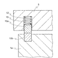
- a columnar shaft member (hereinafter referred to as a first shaft member) 10 a is formed on the bottom surface of the top plate 5 on the bottom surface of the top plate 5, which is a member on the attachment target body side of the door 1 a.
- the lower end of the recessed portion 12 protrudes downward from the lower surface of the top plate 5.
- a cylindrical shaft member (hereinafter referred to as a second shaft member) 10b protrudes slightly flush with the upper surface of the door 1a at a position facing the first shaft member 10a. Embedded and fixed.
- the first shaft member 10a is made of iron, and the second shaft member 10b is made of a magnet.
- the first shaft member 10a is attracted to the second shaft member 10b, and the door 1a is rotatably fixed to the top plate 5 by the attraction force of the magnet.
- the first shaft member is not limited to iron, and can be a ferromagnetic material such as a magnetic material or martensitic stainless steel.
- the type of magnet is not particularly limited, but it is preferable to use a permanent magnet such as a ferrite magnet or a neodymium magnet that is easy to handle.
- the first shaft member 10a is attached to the top plate 5 via a spring 15 that is an elastic body. Therefore, the first shaft member 10 a is movable along the axial direction within the expansion / contraction range of the spring 15 and slides in the recess 12.
- the spring 15 biases the first shaft member 10 a toward the top plate 5, which is the direction opposite to the magnet attracting direction, that is, the direction in which the first shaft member 10 a does not protrude from the lower surface of the top plate 5.
- the lower end of the first shaft member 10 a does not protrude from the lower surface of the top plate 5 and is substantially flush with the lower surface of the top plate 5 before the door 1 a is fixed.
- the door 1a when the door 1a is fixed to the furniture A on the other hand, it moves toward the opposing second shaft member 10b by the attractive force of the magnet against the urging force of the spring 15, as shown in FIG. And abuts against the second shaft member 10b.
- the elastic body is not limited to a spring, and may be rubber, sponge, or the like.
- the second shaft member is fixed by fitting, pins, screws, adhesives, or the like.
- the lower end surface of the first shaft member 10a and the upper end surface of the second shaft member 10b, that is, the opposing surfaces of the shaft member are both flat surfaces, and no recess is formed.
- the lower surface of the top plate 5 and the upper surface of the door 1a are also flat, and no unevenness for fixing the unevenness of the door 1a is formed.
- the above-described facing surface is a smooth surface, whereby frictional resistance due to contact between the facing surfaces of the shaft members is reduced, and the door 1a can be easily rotated and detached from the furniture A.
- the rotation of the lower end of the door 1a is fixed by a known bearing, but the same configuration as that at the upper end of the door 1a described above can be used. Since the door opening / closing structure of door 1b is basically the same as that of door 1a, description thereof will not be repeated.
- FIG. 9 is a schematic cross-sectional view of a door opening and closing structure according to a fifth embodiment of the present invention
- FIG. 10 is a view corresponding to FIG. 9 and is an object to which the door is attached before the door is attached. It is the schematic sectional drawing which showed. Since the configuration of the door opening and closing structure according to the present embodiment is basically the same as that according to the fourth embodiment described above, the differences will be mainly described.
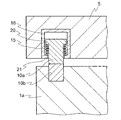
- the door 1a according to the fifth embodiment has a flange 20 formed over the entire outer periphery on the upper side of the first shaft member 10a, and the first shaft member 10a has a longitudinal section.
- the compression spring 15 and the 1st shaft member 10a are accommodated in this casing 16 are the points. It is different from that according to the fourth embodiment.
- the casing 16 is a member having a cylindrical shape, and houses the first shaft member 10a and the spring 15 in the hollow portion.
- An edge 21 extending toward the center over the entire circumference is formed on the lower surface of the casing 16, and the inner side of the edge 21 is wider than the outer periphery of the main body of the shaft member 10 a and narrower than the outer periphery of the flange 20 of the shaft member 10 a.
- An opening having a diameter is formed.
- a spring 15 is placed on the edge 21, and the lower end of the first shaft member 10 a is inserted through the opening on the lower surface of the casing 16 via the spring 15.
- the first shaft member 10 a is urged by the spring 15 in the direction opposite to the magnet attracting direction, that is, the direction in which the first shaft member 10 a does not protrude from the lower surface of the top plate 5. .
- the first shaft member 10 a has a lower end of the first shaft member 10 a that does not protrude from the lower surface of the top plate 5 before the door 1 a is fixed.
- the material of the casing 16 is not particularly limited, and nonmagnetic metal, synthetic resin, or wood can be used.
- the door and the attachment target body can be fixed by the attractive force of the magnet.
- the door can be easily removed against the magnet's attractive force while being fixed by the magnet's attractive force, and the door can be easily attached and detached.
- one shaft member is configured to be movable along the axial direction, a gap is formed between the door and the mounting target body. Even if it is, the one shaft member can approach and contact
- the attachment object of the door was furniture, it is not limited to this, It can apply widely to a box, a building, or an electronic device.
- the openable door is not limited to a pair of left and right doors or a single door, but can be applied to a vertically openable door or a lid-like door, and is also applicable to a door having three or more doors. be able to.
- the opening / closing also includes a partial opening / closing and a half-open state.
- the door is not limited to wood, but may be made of a non-magnetic material, and can be made of synthetic resin or aluminum.
- the door opening / closing structure of this invention was provided in one side of the upper end side or lower end side of a door, it is not limited to this, Embodiment which is different in each of the both ends of a door
- the rotation axis of the door is not limited to the vertical direction, and when the door opening / closing structure of the present invention is applied to a vertical opening / closing type or lid-like door whose rotation axis is a horizontal direction, Both can be provided with door opening and closing structures. The same applies to the case where the rotation axis of the door is inclined.
- the door opening / closing structure of the present invention can be applied to the rotation shaft of the hinge attached to the door.
- the fixing of the shaft member is not limited to the fixing to be embedded in the door or the object to be attached, and can be externally attached.
- the shaft member is disposed so as to be substantially flush with the mounting surface, but the present invention is not limited to this, and the shaft member is disposed so as to protrude from the mounting surface. It may be arranged so that it does not protrude from the mounting surface and is flush with the mounting surface or is recessed from the mounting surface. Further, the shaft member is not limited to being embedded in the door or the mounting target body, and can be externally attached to the door or the mounting target body.
- the shape of the shaft member is a cylindrical shape, but is not limited to this, and may be a prismatic shape, a spherical shape, a flat plate shape, or the material of the shaft member.
- Both shaft members can be magnets.
- the shaft members are arranged so that the magnetic poles at the opposite ends of the two shaft members are different.
- the shaft member is not limited to only a magnet or a magnetic material, and may be a member including a magnet or a magnetic material. Examples of such members include a casing containing a magnet and a molded product made of a synthetic resin in which magnets and magnetic materials are mixed in the form of particles.
- the smooth surface was formed in the shaft member by the side of a door, and the shaft member by the side of a target object, this smooth surface may be formed by grinding
- a lubricant is provided on at least one of the facing surfaces of the door-side shaft member and the object-side shaft member. Is preferred. Lubricants include plating such as nickel, coating film made of synthetic resin such as Teflon (registered trademark), sheet member made of hard synthetic resin such as Duracon (registered trademark) and rubber, wooden plate, synthetic Examples include resin-coated paper and lubricating oil.
- the thickness of these sliding materials may be such that the suction force of the shaft member on the door side and the shaft member on the object side is not significantly reduced, and should be as thin as possible, preferably 2 mm or less.
- the sheet member, the wooden plate, and the coated paper can be fixed to the shaft member with an adhesive.
- the contact and contact of the opposing surfaces of the shaft member in the present invention include contact and contact through the above-mentioned lubricant.
- the door is rotatably fixed to the side wall of the furniture.
- the present invention is not limited to this, and the present embodiment is used when the door and the door are rotatably fixed.
- the door opening / closing structure of the invention can be incorporated. In that case, the attachment object of one door is the other door.
- the movable shaft member was attached to the furniture which is an attachment object of a door, it is not limited to this, Even if it attaches to the door side It can be attached to both the door side and the mounting target body side.
Landscapes
- Engineering & Computer Science (AREA)
- Mechanical Engineering (AREA)
- Civil Engineering (AREA)
- Structural Engineering (AREA)
- Hinges (AREA)
- Wing Frames And Configurations (AREA)
Abstract
Priority Applications (4)
| Application Number | Priority Date | Filing Date | Title |
|---|---|---|---|
| US13/808,963 US8839561B2 (en) | 2010-08-06 | 2011-07-28 | Door opening/closing structure |
| EP11814550.7A EP2597236A4 (fr) | 2010-08-06 | 2011-07-28 | Structure d'ouverture/de fermeture de porte |
| KR1020137005684A KR101523151B1 (ko) | 2010-08-06 | 2011-07-28 | 문 개폐 구조 |
| CN201180038437.9A CN103052760B (zh) | 2010-08-06 | 2011-07-28 | 门开闭构造 |
Applications Claiming Priority (4)
| Application Number | Priority Date | Filing Date | Title |
|---|---|---|---|
| JP2010-177729 | 2010-08-06 | ||
| JP2010177729A JP4846046B1 (ja) | 2010-08-06 | 2010-08-06 | 扉開閉構造 |
| JP2010-271939 | 2010-12-06 | ||
| JP2010271939A JP5444200B2 (ja) | 2010-12-06 | 2010-12-06 | 扉開閉構造 |
Publications (1)
| Publication Number | Publication Date |
|---|---|
| WO2012017924A1 true WO2012017924A1 (fr) | 2012-02-09 |
Family
ID=45559425
Family Applications (1)
| Application Number | Title | Priority Date | Filing Date |
|---|---|---|---|
| PCT/JP2011/067351 Ceased WO2012017924A1 (fr) | 2010-08-06 | 2011-07-28 | Structure d'ouverture/de fermeture de porte |
Country Status (5)
| Country | Link |
|---|---|
| US (1) | US8839561B2 (fr) |
| EP (1) | EP2597236A4 (fr) |
| KR (1) | KR101523151B1 (fr) |
| CN (1) | CN103052760B (fr) |
| WO (1) | WO2012017924A1 (fr) |
Cited By (6)
| Publication number | Priority date | Publication date | Assignee | Title |
|---|---|---|---|---|
| CN103161396A (zh) * | 2013-03-26 | 2013-06-19 | 北京闼闼同创工贸有限公司 | 开关门 |
| GB2503953A (en) * | 2012-07-14 | 2014-01-15 | Jonathan Stephen Prestwich | A door with magnetic hinges which can be opened from two opposite edges |
| US20160258200A1 (en) * | 2015-03-04 | 2016-09-08 | Bobrick Washroom Equipment, Inc. | Partition and closing system for partition |
| CN106460424A (zh) * | 2014-04-24 | 2017-02-22 | 阿普赛特技术有限公司 | 用于气流控制的门系统 |
| CN109068893A (zh) * | 2016-02-05 | 2018-12-21 | 野醍冷却器有限责任公司 | 绝热容器和形成这种容器的方法 |
| US10500267B2 (en) | 2014-03-17 | 2019-12-10 | Flugen, Inc. | Influenza virus vectors and uses therefor |
Families Citing this family (13)
| Publication number | Priority date | Publication date | Assignee | Title |
|---|---|---|---|---|
| ES2497365B1 (es) * | 2013-03-19 | 2014-12-22 | Yeray SUÁREZ GONZÁLEZ | Bisagra para puertas |
| FR3016386A1 (fr) * | 2014-01-14 | 2015-07-17 | Marc Tauss | Ensemble support/porte multidirectionnelle |
| WO2015130247A1 (fr) * | 2014-02-25 | 2015-09-03 | Fathi Kiliç | Lave-linge doté d'une porte bidirectionnelle |
| US20170079492A1 (en) * | 2014-05-22 | 2017-03-23 | Nilfisk A/S | A cleaning machine, such as a vacuum cleaner comprising a housing, and a hingeable element being detachably attachable thereto |
| KR20160018172A (ko) * | 2014-08-08 | 2016-02-17 | 삼성전자주식회사 | 도어 고정장치 및 이를 갖는 냉장고 |
| DE202014009636U1 (de) * | 2014-12-03 | 2016-03-04 | GM Global Technology Operations LLC (n. d. Ges. d. Staates Delaware) | Staufach für ein Fahrzeug und Fahrzeug mit dem Staufach |
| WO2018189206A1 (fr) | 2017-04-10 | 2018-10-18 | Safehinge Limited | Charnière, battant et procédés associés |
| CN111305728A (zh) * | 2018-12-11 | 2020-06-19 | 北京闼闼同创工贸有限公司 | 一种门及密封装置 |
| CN114828750A (zh) * | 2019-12-19 | 2022-07-29 | 皇家飞利浦有限公司 | 用于便携式医疗装置的接入门的分离式铰链 |
| DE102020206873A1 (de) * | 2020-06-03 | 2021-12-09 | B.Braun Avitum Ag | Medizinisches Gerät zur extrakorporalen Blutbehandlung |
| BE1028741B1 (nl) * | 2020-10-27 | 2022-05-24 | Arlu Nv | Speunscharnier |
| IT202100019460A1 (it) * | 2021-07-22 | 2023-01-22 | Ol Mi S R L | Dispositivo per l’accoppiamento girevole di un elemento di chiusura, quale un’anta, una porta o similare e di una struttura di supporto stazionaria, quale un telaio, nonche assieme e sistema di movimentazione girevole di un elemento di chiusura comprendente tale dispositivo |
| AU2023204931A1 (en) * | 2022-01-10 | 2024-07-25 | Safehinge Primera Limited | Coupling and associated methods |
Citations (5)
| Publication number | Priority date | Publication date | Assignee | Title |
|---|---|---|---|---|
| JPH03160035A (ja) | 1989-11-17 | 1991-07-10 | Mitsubishi Rayon Co Ltd | プリプレグシート |
| JPH11324466A (ja) * | 1998-05-08 | 1999-11-26 | Tateyama Alum Ind Co Ltd | 竪框用ヒンジ及びそれを利用した浴室用折戸 |
| JP2002021411A (ja) | 2000-07-03 | 2002-01-23 | Shibutani:Kk | ドア用ヒンジ |
| JP2007335929A (ja) * | 2006-06-12 | 2007-12-27 | Sharp Corp | 壁掛けテレビ |
| JP2009287332A (ja) * | 2008-05-30 | 2009-12-10 | Yogo Jukin Sangyo Co Ltd | 扉体の反り矯正構造及びそれを用いた扉ユニット |
Family Cites Families (21)
| Publication number | Priority date | Publication date | Assignee | Title |
|---|---|---|---|---|
| US3152716A (en) * | 1961-08-02 | 1964-10-13 | Expandolite Inc | Container |
| DE3117505C2 (de) * | 1981-05-02 | 1983-05-19 | Frank, Bernd, 8881 Unterglauheim | Magnetisches Getriebe zum Umsetzen einer Hin- und Herbewegung in eine Drehbewegung und umgekehrt |
| JPH03162614A (ja) * | 1989-11-20 | 1991-07-12 | Daihatsu Motor Co Ltd | 車両方位検出装置 |
| JP3208453B2 (ja) | 1990-12-14 | 2001-09-10 | 株式会社パイオラックス | 自動車のコンソールボックス用等の両開き開閉装置 |
| JP3160035B2 (ja) | 1991-11-13 | 2001-04-23 | マツダ株式会社 | 排気ガス浄化用触媒の製造方法 |
| JP3162614B2 (ja) * | 1995-10-27 | 2001-05-08 | 株式会社荏原製作所 | 高流速逆洗型イオン交換塔の再生方法 |
| US20030167599A1 (en) * | 2002-03-07 | 2003-09-11 | David Seidler | Magnetic hinge |
| US7055216B2 (en) * | 2002-03-07 | 2006-06-06 | Concept Workshop Worldwide Llc | Magnetic hinge |
| CN2568789Y (zh) * | 2002-07-01 | 2003-08-27 | 陈耕农 | 门框直角接头构造 |
| JP2005105788A (ja) * | 2003-09-29 | 2005-04-21 | Takuma Sangyo:Kk | 蝶番装置及びこれを用いたドア装置 |
| DE202004007127U1 (de) * | 2004-05-03 | 2004-08-05 | Bäcker, Carsten | Präsentationsvorrichtung |
| US7657971B2 (en) * | 2005-05-12 | 2010-02-09 | Peter Danko | Virtual hinge |
| US20070157432A1 (en) * | 2006-01-11 | 2007-07-12 | Glenn Weinstein | Magnetic hinge |
| AT503949B1 (de) * | 2006-03-08 | 2008-02-15 | Blum Gmbh Julius | Schliess- und öffnungsvorrichtung für ein an einem möbel bewegbar gelagertes möbelteil |
| EP2082281A4 (fr) * | 2006-10-27 | 2010-03-10 | Pixeloptics Inc | Branche de lunettes pour verres |
| JP5608164B2 (ja) * | 2007-08-06 | 2014-10-15 | クリストファー スチュアート,マイケル | ヒンジ |
| US20090195747A1 (en) * | 2008-02-04 | 2009-08-06 | Insua Luisa M | Interchangeable eyeglass temples |
| FR2955137B1 (fr) * | 2010-01-12 | 2014-01-17 | Diam Internat Sas | Dispositif formant charniere magnetique |
| US8289115B2 (en) * | 2010-09-17 | 2012-10-16 | Apple Inc. | Sensor fusion |
| ITMI20110127U1 (it) * | 2011-04-14 | 2012-10-15 | Tucano S R L | Custodia per un dispositivo elettronico di tipo tablet, in particolare un tablet computer |
| WO2013067480A2 (fr) * | 2011-11-03 | 2013-05-10 | Phyzics Properties, Inc. | Charnière magnétique |
-
2011
- 2011-07-28 CN CN201180038437.9A patent/CN103052760B/zh not_active Expired - Fee Related
- 2011-07-28 WO PCT/JP2011/067351 patent/WO2012017924A1/fr not_active Ceased
- 2011-07-28 KR KR1020137005684A patent/KR101523151B1/ko not_active Expired - Fee Related
- 2011-07-28 EP EP11814550.7A patent/EP2597236A4/fr not_active Withdrawn
- 2011-07-28 US US13/808,963 patent/US8839561B2/en not_active Expired - Fee Related
Patent Citations (5)
| Publication number | Priority date | Publication date | Assignee | Title |
|---|---|---|---|---|
| JPH03160035A (ja) | 1989-11-17 | 1991-07-10 | Mitsubishi Rayon Co Ltd | プリプレグシート |
| JPH11324466A (ja) * | 1998-05-08 | 1999-11-26 | Tateyama Alum Ind Co Ltd | 竪框用ヒンジ及びそれを利用した浴室用折戸 |
| JP2002021411A (ja) | 2000-07-03 | 2002-01-23 | Shibutani:Kk | ドア用ヒンジ |
| JP2007335929A (ja) * | 2006-06-12 | 2007-12-27 | Sharp Corp | 壁掛けテレビ |
| JP2009287332A (ja) * | 2008-05-30 | 2009-12-10 | Yogo Jukin Sangyo Co Ltd | 扉体の反り矯正構造及びそれを用いた扉ユニット |
Non-Patent Citations (1)
| Title |
|---|
| See also references of EP2597236A4 |
Cited By (10)
| Publication number | Priority date | Publication date | Assignee | Title |
|---|---|---|---|---|
| GB2503953A (en) * | 2012-07-14 | 2014-01-15 | Jonathan Stephen Prestwich | A door with magnetic hinges which can be opened from two opposite edges |
| CN103161396A (zh) * | 2013-03-26 | 2013-06-19 | 北京闼闼同创工贸有限公司 | 开关门 |
| US10500267B2 (en) | 2014-03-17 | 2019-12-10 | Flugen, Inc. | Influenza virus vectors and uses therefor |
| US11253584B2 (en) | 2014-03-17 | 2022-02-22 | Flugen, Inc. | Influenza virus vectors and uses therefor |
| US11980662B2 (en) | 2014-03-17 | 2024-05-14 | Flugen, Inc. | Influenza virus vectors and uses therefor |
| CN106460424A (zh) * | 2014-04-24 | 2017-02-22 | 阿普赛特技术有限公司 | 用于气流控制的门系统 |
| CN106460424B (zh) * | 2014-04-24 | 2018-06-01 | 阿普赛特技术有限公司 | 用于气流控制的门系统 |
| US20160258200A1 (en) * | 2015-03-04 | 2016-09-08 | Bobrick Washroom Equipment, Inc. | Partition and closing system for partition |
| US9879461B2 (en) * | 2015-03-04 | 2018-01-30 | Bobrick Washroom Equipment, Inc. | Partition and closing system for partition |
| CN109068893A (zh) * | 2016-02-05 | 2018-12-21 | 野醍冷却器有限责任公司 | 绝热容器和形成这种容器的方法 |
Also Published As
| Publication number | Publication date |
|---|---|
| US20130111818A1 (en) | 2013-05-09 |
| CN103052760B (zh) | 2015-08-05 |
| KR101523151B1 (ko) | 2015-05-26 |
| CN103052760A (zh) | 2013-04-17 |
| KR20130034056A (ko) | 2013-04-04 |
| EP2597236A4 (fr) | 2016-05-18 |
| EP2597236A1 (fr) | 2013-05-29 |
| US8839561B2 (en) | 2014-09-23 |
Similar Documents
| Publication | Publication Date | Title |
|---|---|---|
| WO2012017924A1 (fr) | Structure d'ouverture/de fermeture de porte | |
| JP5608164B2 (ja) | ヒンジ | |
| US10513871B2 (en) | Knob lock and lock box having the same | |
| CN111043659B (zh) | 导风板闭合结构、空调器 | |
| JP5400741B2 (ja) | 扉開閉構造 | |
| JP5444200B2 (ja) | 扉開閉構造 | |
| JP4846046B1 (ja) | 扉開閉構造 | |
| CN205840585U (zh) | 磁吸式门挡铰链器 | |
| JP7122751B2 (ja) | 磁石利用自動ドア構造 | |
| CN108064318B (zh) | 一种拉手组件及淋浴门 | |
| JP5426466B2 (ja) | 戸当り | |
| JP2012057292A (ja) | 着脱自在に構成された蝶番構造 | |
| JP5793462B2 (ja) | 扉開閉構造 | |
| JP3160036U7 (fr) | ||
| JP3202406U (ja) | マグネットダンピングステー | |
| JP3160035U (ja) | 仏壇 | |
| JP3894556B2 (ja) | ネット収納枠付き網戸 | |
| CN120319115A (zh) | 一种多功能智能日历 | |
| CN107620535B (zh) | 磁吸式门挡铰链器 | |
| TW201802342A (zh) | 磁吸式門擋鉸鏈器 | |
| CN100442959C (zh) | 具有磁力式旋转盖板的装置 | |
| JP2005147323A (ja) | ヒンジ | |
| CN210853599U (zh) | 磁力旋转定位结构 | |
| JP2002089120A (ja) | 無塵蝶番 | |
| JP2015132356A (ja) | 回転軸のブレーキ装置 |
Legal Events
| Date | Code | Title | Description |
|---|---|---|---|
| WWE | Wipo information: entry into national phase |
Ref document number: 201180038437.9 Country of ref document: CN |
|
| 121 | Ep: the epo has been informed by wipo that ep was designated in this application |
Ref document number: 11814550 Country of ref document: EP Kind code of ref document: A1 |
|
| WWE | Wipo information: entry into national phase |
Ref document number: 13808963 Country of ref document: US |
|
| NENP | Non-entry into the national phase |
Ref country code: DE |
|
| WWE | Wipo information: entry into national phase |
Ref document number: 2011814550 Country of ref document: EP |
|
| ENP | Entry into the national phase |
Ref document number: 20137005684 Country of ref document: KR Kind code of ref document: A |