WO2012033094A1 - Spectromètre de masse à temps de vol - Google Patents
Spectromètre de masse à temps de vol Download PDFInfo
- Publication number
- WO2012033094A1 WO2012033094A1 PCT/JP2011/070270 JP2011070270W WO2012033094A1 WO 2012033094 A1 WO2012033094 A1 WO 2012033094A1 JP 2011070270 W JP2011070270 W JP 2011070270W WO 2012033094 A1 WO2012033094 A1 WO 2012033094A1
- Authority
- WO
- WIPO (PCT)
- Prior art keywords
- electric field
- region
- potential
- time
- deceleration
- Prior art date
- Legal status (The legal status is an assumption and is not a legal conclusion. Google has not performed a legal analysis and makes no representation as to the accuracy of the status listed.)
- Ceased
Links
Images


Classifications
-
- H—ELECTRICITY
- H01—ELECTRIC ELEMENTS
- H01J—ELECTRIC DISCHARGE TUBES OR DISCHARGE LAMPS
- H01J49/00—Particle spectrometers or separator tubes
- H01J49/26—Mass spectrometers or separator tubes
- H01J49/34—Dynamic spectrometers
- H01J49/40—Time-of-flight spectrometers
- H01J49/405—Time-of-flight spectrometers characterised by the reflectron, e.g. curved field, electrode shapes
Definitions
- the present invention relates to a time-of-flight mass spectrometer, and more particularly, to a time-of-flight mass spectrometer using a reflectron (reflector).
- a time-of-flight mass spectrometer (time-of-flight-mass-spectrometer, hereinafter referred to as “TOFMS”) utilizes the fact that the flight speed of each ion when accelerating various ions depends on the mass-to-charge ratio, making the ions constant The flight time of each ion when flying for a distance is measured, and the mass-to-charge ratio for each ion is calculated from the flight time.
- TOFMS the flight speed of ions depends on the initial energy given by the electric field, etc., so the flight time of each ion has energy dependence, and the initial energy width of the ion packet (a group of ions having the same mass-to-charge ratio) is Affects the mass resolution of the instrument. For this reason, in TOFMS, improving the energy convergence of the ion flight time is one of the major issues for improving the performance.
- a widely known effective solution to the above problem is to use a reflectron that achieves time-of-flight energy convergence by reflecting ions with a reflected electric field.
- ions with higher energy that is, higher velocity
- the difference in the path length corrects the time-of-flight deviation with respect to the variation in the initial energy of ions, and improves the energy convergence of the time of flight.
- the flight distance can be increased while suppressing the size of the entire apparatus.
- TOFMS as the flight distance is longer, the mass resolution is improved. Therefore, using the reflectron has an advantage that the mass resolution can be improved while suppressing the size and cost of the apparatus.
- the simplest structure of the reflectron is a one-stage reflectron that uses a uniform deceleration electric field with a constant electric field intensity as the reflected electric field, but the single-stage reflectron achieves sufficient time-of-flight energy convergence. I can't do it. Therefore, the reflectron widely used at present is a two-stage reflectron having a structure in which two types of uniform deceleration electric fields are combined as a reflected electric field to reflect ions in the second-stage electric field (Non-Patent Document). 1).
- the energy convergence of the flight time higher than that of the first-stage reflectron is achieved by adjusting the dimensions such as the length and the two kinds of electric field strengths. be able to.
- the two-stage reflectron has been adopted in almost all commercially available TOFMSs as a method capable of achieving relatively high performance with a simple structure.
- the flight time of ions has energy dependence.
- the flight time of ions is expressed by a series expansion with respect to the initial energy of ions.
- the initial energy is U for ions of mass m and valence z.
- the reference initial energy is U 0 and the flight time is T 0 .
- the time-of-flight T 0 is a function including the device size and the like as a constant factor, and having the ion mass-to-charge ratio m / z as a variable.
- the flight time T of ions having an arbitrary initial energy U is expressed by the following equation (1) using the flight time T 0 of the reference ions and the reference initial energy U 0 .
- Equation (1) is an expression in which the time of flight is series-expanded by the ratio of the energy displacement to the reference ion.
- T 1 , T 2 ,... which are coefficients of the next terms of the development, are called time-of-flight aberration coefficients and are represented by device parameters such as device dimensions and voltage conditions.
- the method of reducing the energy dependency of the time of flight is a method of adjusting the apparatus parameters so that the aberration coefficient becomes zero in as many orders as possible in order from the low-order term, as in the existing aberration theory. is there.
- the aberration coefficient up to the second order is made zero by appropriately adjusting the length and electric field strength of the two uniform deceleration electric fields, Second order energy convergence can be achieved.
- the third-order or higher order aberration coefficient is not zero, and the energy dependence of the flight time due to these remains. For this reason, if the initial energy width of the ions is large, the observed time-of-flight peak width is also large, and the mass resolution is lowered.
- Patent Document 2 discloses a flight equivalent to a one-stage reflectron even when the function form of the reflected electric field intensity distribution is changed and the starting point of ions and the detector are separated from the reflected electric field by free space. Methods have been proposed to achieve time energy convergence over a wider energy range.
- the present invention has been made to solve the above-mentioned problems, and its main purpose is to reduce the energy dependence of the flight time of ions while ensuring a high degree of freedom in the structural design and circuit design of actual devices. By improving, it is providing the time-of-flight mass spectrometer which can implement
- the time-of-flight mass spectrometer uses a characteristic technique to determine the shape of the electrostatic field formed by the reflectron that reflects ions, that is, the potential distribution along the central axis.
- the derived shape is used.
- the present invention made to solve the above-described problems is based on energy application means for applying a certain energy to fly ions to be analyzed, and ions to which the energy is applied according to the difference in flight time.
- a time-of-flight mass spectrometer comprising a time-of-flight mass separation means for separating each mass to charge ratio
- the mass separation means includes a free flight space in which ions freely fly without being affected by an electric field, and a plurality of electrodes for reflecting and folding ions flying in the free flight space by the action of an electric field
- a voltage applying means for applying a DC voltage to each electrode of the reflectron
- the voltage applying means is The electrostatic field formed by the reflectron is virtually divided into a deceleration region for decelerating the introduced ions and a reflection region for returning ions decelerated through the deceleration region along the direction of ion travel.
- the potential distribution along the central axis of the electrostatic field in the deceleration region is a potential distribution defined by one type of function, or a combination of potential distributions defined by different types of functions along the central axis
- the potential distribution along the central axis of the electrostatic field in the reflection region is one kind of curved potential distribution, and an initial energy equal to the reference potential U 0 set to be equal to or less than the maximum potential value U d in the deceleration region.
- the total flight time when an ion having an initial energy E of E> U d makes a return flight including the free flight space.
- a conditional expression to be satisfied of the flight time T r (E) of ions in the reflection region is determined so that the flight time becomes equal, and the curved potential of the reflection region that realizes the flight time T r (E) is defined.
- the following equation (2) is used as a relational expression for obtaining the inverse function x (U) of the distribution U (x), and the integral calculation in the equation (2) defines the potential distribution of the electrostatic field in the deceleration region.
- Parameter so that analytic equations or numerical calculation is determined by the numerical solution by a curved potential distribution using, is characterized by applying a voltage to each electrode. Where m is the mass of any desired ion, and U is the initial energy imparted to this ion.
- the reflectron is typically composed of a plurality of ring-shaped electrodes arranged along the central axis direction, and a direct current applied to each ring-shaped electrode.
- the electrostatic field formed in the space surrounded by the ring electrodes can be made to show the above-described potential distribution.
- the electrode constituting the reflectron is not limited to a ring-shaped electrode, and the form is not particularly limited as long as an electrostatic field showing a desired potential distribution can be formed in a space into which ions are introduced.
- the shape of the potential distribution formed by the voltages applied to the plurality of electrodes constituting the reflectron varies depending on the arrangement of the electrodes, the shape of the electrodes, and the like, for example, a plurality of states in which adjacent electrode intervals are appropriately adjusted.
- a desired potential distribution can also be realized by applying a predetermined DC voltage to each of the electrodes.
- the deceleration region is a system that reduces the kinetic energy of ions as a whole, and ions that fly by being given a predetermined initial energy. If it is guaranteed that it can pass through while decelerating (that is, it does not return without reaching the reflection area), a part where there is no electric field (that is, a part where ions fly freely) ) Or an accelerating electric field may be present. If these conditions are satisfied, there is no particular restriction on the shape of the potential distribution in the deceleration region and the like, and it can be appropriately determined depending on the design convenience.
- the potential distribution of the electrostatic field in the deceleration region is determined in this way, for example, in addition to the potential value at the boundary between the deceleration region and the reflection region (in other words, the maximum potential value in the deceleration region) U d .
- the curved potential distribution of the electrostatic field in the reflection region from the above x (U) U (x) can be determined uniquely.
- the integral in the function x (U) may not be obtained analytically.
- a numerical solution can be obtained by solving the integral by calculation, and the curved potential distribution U (x) of the electrostatic field in the reflection region can be uniquely obtained.
- the entire electrostatic field formed by the reflectron is not considered as one region, but is considered as being divided into a deceleration region and a reflection region based on the action on ions.
- a potential distribution is first determined for the deceleration region, and further, a reference potential U 0 that is equal to or less than the maximum potential value U d of the deceleration region, regardless of the initial energy of ions, at the boundary between the deceleration region and the reflection region or within the deceleration region.
- An ion with a mass-to-charge ratio having an initial energy larger than U d starting from a predetermined point is introduced into the reflection region through the free flight space and the deceleration region, and is folded back in the reflection region to the original point.
- the total flight time to return is equal to the total flight time of ions of the same mass-to-charge ratio with the trajectory turning back at the boundary between the deceleration region and the reflection region or at the reference potential value in the deceleration region. Define the potential distribution.
- the degree of freedom of the potential distribution in the deceleration region is large, practically, if the potential distribution function in the deceleration region is complicated, the calculation of the potential distribution function in the reflection region becomes complicated. Further, as described above, when the numerical solution is obtained by solving the integral by a specific numerical calculation instead of the analytical solution, the calculation becomes more complicated. Therefore, it is desirable that the potential distribution function in the deceleration region be as simple as possible within a range in which desired performance (mass resolution, etc.) can be obtained as a time-of-flight mass spectrometer.
- the deceleration region is composed of a two-stage uniform deceleration electric field defined by a function having two different types of linear potential gradients,
- the curved potential distribution along the central axis of the electrostatic field of the reflection region is such that the reference potential U 0 is set equal to the maximum potential U d of the deceleration region, the length of the free flight space is L, and the first stage in the deceleration region
- the ratio of the length of the uniform deceleration electric field in the second stage to the length of the free flight space is d 1 and d 2 , respectively, and the potential height of the uniform deceleration electric field in the first stage is U 1 .
- the deceleration region is a two-stage uniform deceleration electric field defined by a function having two different types of linear potential gradients, and an auxiliary that is not affected by the electric field disposed between the two stages of the uniform deceleration electric field.
- the curved potential distribution along the central axis of the electrostatic field of the reflection region is such that the reference potential U 0 is set equal to the maximum potential U d of the deceleration region, the length of the free flight space is L, and the first stage in the deceleration region
- the ratios of the uniform deceleration electric field, the auxiliary free flight space, and the length of the second stage uniform deceleration electric field to the length of the free flight space are d 1 , f, and d 2 , respectively.
- the potential height of the electric field is U 1
- u U / U d
- u 1 U 1 /
- U d , u 2 U 2 / U d
- the configuration may be determined by the inverse function x (u) of the following equation (5).
- the acceleration potential distribution in the energy applying means for applying energy for flying ions is not considered, but by specifying this acceleration potential distribution, the flight time of ions generated in the acceleration portion can be reduced. It is possible to derive a more appropriate potential distribution in the reflection region that removes the energy dependence for the entire flight time, including deviations.
- the energy applying means includes a one-step uniform acceleration electric field defined by a function having a linear downward potential gradient in the direction of ion travel, while the deceleration region includes two different types of linear potential gradients.
- the reference potential U 0 is set equal to the maximum potential U d of the deceleration region
- the maximum potential of the uniform acceleration electric field is U a
- the free flight space L the length of the uniform acceleration electric field, the length of the first uniform deceleration electric field in the deceleration region, and the length of the second uniform deceleration electric field with respect to the length of the free flight space
- the deceleration region is composed of a single-stage uniform deceleration electric field defined by a function having a linear potential gradient
- the reference potential U 0 is set equal to the maximum potential U d of the deceleration region
- the length of the free flight space is L
- the length of the deceleration region is When the ratio to the length of the free flight space is d, it is determined by the inverse function x (U) of the following equation (9), and d is set in the range of 0.2 ⁇ d ⁇ 0.8. It is good also as composition which has.
- the energy applying means includes a one-stage uniform acceleration electric field defined by a function having a linear downward potential gradient in the direction of ion travel, while the deceleration region is a function having a linear potential gradient.
- the reference potential U 0 is set equal to the maximum potential U d of the deceleration region
- the maximum potential of the uniform acceleration electric field is U a
- the free flight space Is the length of L
- the ratio of the length of the uniform acceleration electric field and the length of the deceleration region to the length of the free flight space is a and d, respectively
- u U / U d
- u a U a / U
- a configuration determined by the inverse function x (u) of the following equation (10) is preferable.
- the voltage applying means applies a voltage by resistance division to at least one of the plurality of electrodes constituting the reflectron, A desired potential distribution may be obtained by adjusting the distance between the electrode and the adjacent electrode.
- the voltage applying means includes a ladder-type resistance dividing circuit, and each of the electrodes excluding the electrodes at both ends of the plurality of electrodes constituting the reflection region in the reflectron is divided by resistance division. It may be configured to apply.
- the cost can be further reduced, and it is easy to align the characteristics such as the temperature coefficient of resistance and ensure performance. It is advantageous.
- the time-of-flight mass spectrometer according to the present invention is a so-called reflectron time-of-flight mass spectrometer using only one round-trip flight trajectory using one free flight space and one reflectron.
- one free flight space and one reflectron are set as a pair, and two reflectrons are arranged facing each other across two sets of two free flight spaces, and multiple times between both reflectrons.
- a multi-reflection reflectron time-of-flight mass spectrometer that reflects ions can also be used.
- the introduction of ions into the deceleration region of the reflectron does not necessarily need to coincide with the central axis direction of the reflectron.
- the ion introduction direction is oblique with respect to the central axis direction
- the ion path after returning in the reflection area does not coincide with the ion path (outward path) toward the reflection area, but it has a spatial potential. If the distribution is rotationally symmetric around the central axis, the behavior of the ions is the same as when the forward and return paths match, even if the forward and return paths do not match. Is the same.
- the energy dependence of the flight time of ions can be completely removed theoretically, so that a higher mass resolution can be achieved as compared with the conventional device.
- the potential distribution function in the deceleration region of the reflectron can be freely determined to some extent, so that the energy independence of the ion flight time is achieved.
- the degree of freedom in device design can be provided, and not only the design is facilitated, but also the device is downsized and the cost is reduced.
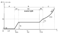
- region is a 2-step uniform deceleration electric field in TOFMS which concerns on this invention.
- region is a two-step uniform deceleration electric field in TOFMS which concerns on this invention.
- the schematic of potential distribution in flight space when the deceleration region is composed of a two-stage uniform deceleration electric field and an auxiliary free space that separates these electric fields in the TOFMS according to the present invention. Schematic of potential distribution in flight space including acceleration potential in TOFMS according to the present invention.
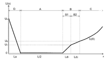
- region is a uniform acceleration electric field and a deceleration area
- region is a 1 step
- region is a uniform acceleration electric field and a deceleration area
- region is a 2 step
- region is a 2-stage uniform deceleration electric field.
- the figure which shows the simulation result of the TOF peak waveform with respect to the voltage change shown in FIG. The schematic block diagram of TOFMS by one Example of this invention.
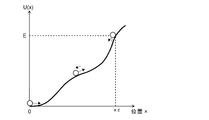
- FIG. 1 is a conceptual diagram showing the potential distribution in the reflected electric field and the behavior of ions.
- the horizontal axis is the position x on the central axis in the reflected electric field
- the vertical axis is the potential U (x).
- ions given initial energy E travel while being decelerated by increasing the gradient due to the potential in the reflected electric field, and at a position x E where the reflected electric field potential is the same height as initial energy E. It returns to the original position, that is, the origin.
- the above expression (11) is an expression that gives a round-trip flight time in the reflected electric field of ions when an arbitrary potential is given. Looking back at the relationship between the position x and the potential U (x), given the round-trip flight time in the reflected electric field of ions, the following equation (12) is given to give the potential distribution that realizes the flight time: The formula can be obtained.
- x (U) can be regarded as a function that gives a position x where the potential energy is U, and is an inverse function of the potential distribution function U (x) in the equation (11). Therefore, if this function x (U) is given, it is easy to obtain the inverse function U (x), that is, the potential distribution function.
- Equation (12) As a simple example, an example is given in which a potential shape is obtained by using equation (12) so that the flight time of reciprocal motion of ions in the reflected electric field does not depend on energy. Assuming that Ta is a time-of-flight constant that does not depend on energy, the following equation (13) is obtained by substituting this into equation (12). The integration operation on the right side of equation (14) can be easily executed, and its value is 2 ⁇ U. Thus, the obtained potential distribution function U (x) is expressed by the following equation (14). This equation (14) indicates that the potential distribution of the reflected electric field is parabolic, and is consistent with the content derived in Patent Document 1. From this, it is understood that a potential distribution function that gives a desired flight time can be obtained by using the equation (12).
- the potential distribution of the reflected electric field can be obtained so that the flight time of ions does not have energy dependency. It is possible to overcome the above problems caused by the above.
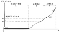
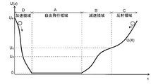
- a free flight region A without an electric field is provided in front of the reflectron as in the normal reflectron TOFMS, and the reflected electric field formed by the reflectron is decelerated with one or more types of potential distribution along the central axis.
- a region B and a reflection region C having one curved potential distribution.
- the division between the deceleration region B and the reflection region C is only a division from the viewpoint of the action of the electric field on the ions, and is not a physical one.
- ions start from a certain starting point in the free flight region A, pass through the free flight region A and the deceleration region B, and then the potential distribution of the reflection region C and the ion distribution.
- the signal is turned back at the maximum potential point determined by the initial energy, passes again through the deceleration region B and the free flight region A in the direction opposite to the forward path, and is detected by the detector.
- An outline of the potential distribution along the central axis at this time is shown in FIG. Note that the potential of the ion optical system is measured using the potential of the free flight region A as a reference (for example, ground potential).
- the deceleration region B may be configured by combining a plurality of regions having different potential distribution functions along the central axis, and even if there is a free flight space in which no electric field exists or a partial acceleration electric field exists Good. That is, the deceleration region B is sufficient if it reduces the kinetic energy of ions as a whole, and there may be a portion that does not decrease kinetic energy or a portion that imparts kinetic energy. However, the portion of the deceleration region B that is in contact with the boundary with the reflection region C is always a deceleration electric field. Therefore, the maximum potential value U d in the deceleration region B is necessarily the potential at the boundary between the deceleration region B and the reflection region C.
- the flight time of ions in the free flight region A is calculated by the following equation (15).
- Equation (16) When the initial energy of ions is U d + E, the flight time of ions from the start point of the deceleration region B to the point where the potential becomes U 1 in the deceleration region B is given by the given potential distribution function of the deceleration region B. Suppose that it is given by the following equation (16). T d (U d + E, U 1 ) (16) Here, U 1 ⁇ U d .
- equation (16) can be calculated analytically, and a specific analytic equation can be given. Even if Equation (16) cannot be calculated analytically, the value can be obtained by numerical calculation.
- the equation (16) basically indicates that when ions travel from the free flight region A, which is the reference potential of the ion optical system, to the deceleration region B, the first flight to the point that matches the potential. It represents time.
- the potential distribution function of the reflection region C is U (x), and its inverse function is x (U).
- the coordinate origin is the start point of the reflection region C.
- T r (E) the round-trip flight time in the reflection region C of the ion whose initial energy is U d + E.
- T (E) the total flight time from when the ions are turned back at the reflection region C through the free flight region A and the deceleration region B and finally return, passes through the deceleration region B twice in the forward and backward directions. Note that this is calculated using equation (17).
- T (E) T 0 (U d + 2E) + 2T d (U d + E, U d ) + T r (E) (17)
- the time-of-flight reference potential U 0 is set to satisfy 0 ⁇ U 0 ⁇ U d as a parameter of the ion optical system that is irrelevant to the initial motion condition of ions.
- the flight time of an ion having an initial energy equal to the time-of-flight reference potential of the ion optical system is defined as T s (U 0 ), and this is called the reference flight time. Since U 0 ⁇ U d , this ion draws a trajectory that turns back at either the maximum potential point in the deceleration region B or the point where the potential becomes U 0 in the deceleration region B.
- the flight time is calculated by equation (18).
- T s (U 0 ) T 0 (U 0 ) + 2T d (U 0 , U 0 ) (18)
- T r (E) T 0 (U 0 ) ⁇ T 0 (U d + E) +2 ⁇ T d (U 0 , U 0 ) ⁇ T d (U d + E, U d ) ⁇ (19)
- the potential distribution function of the reflection region C that realizes such a flight time is calculated from the equation (12) as the following equation (20).
- the equation (20) is given as an algebraic equation when the integration operation on the right side can be analytically executed. Even if the integration cannot be executed analytically, a numerical solution can be obtained by numerical calculation.
- the deceleration region B is a single-stage uniform deceleration electric field having one type of constant electric field strength, and the reference potential is the deceleration region.
- the length of the uniform deceleration electric field is expressed as Ld using a ratio d to the length of the free flight region A. It is assumed that the potential of the free flight area A is zero.
- the initial energy of ions is U d + E
- the time required to pass through the deceleration region B is expressed by equation (21).
- T 0 (U d + E) + 2T d (U d + E, U d ) + T r (E) T 0 (U d ) + 2T d (U d , U d ) Holds.
- the flight time in the reflection region C is expressed by the following equation (22).
- T r (E) T 0 (U d ) ⁇ T 0 (U d + E) +2 ⁇ T d (U d , U d ) ⁇ T d (U d + E, U d ) ⁇ (22)
- the potential shape of the reflection region C that realizes this time of flight is calculated from the equation (20).
- the integral operation in the equation (20) can be executed analytically, and (23).
- U d the reference potential value
- the potential distribution function of region C can be obtained. That is, it is not necessary to sacrifice the energy convergence in order to secure the length of the free flight region A as in the prior art, and an ideal energy-independent reflectron can be configured with a large degree of freedom. .
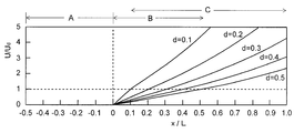
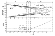
- FIG. 3 is a diagram in which potential shapes for several parameters are obtained by simulation calculation when the deceleration region B is a single-stage uniform deceleration electric field. This is a result when the length of the free flight area A is divided into two equal parts in the forward path and the return path, and the parameter d of the length of the deceleration area B is changed from 0.1 to 0.5.
- the potential is expressed as a ratio to the reference potential.
- the potential due to the first uniform deceleration electric field B1 constituting the deceleration region B is U 1
- the potential due to the second uniform deceleration electric field B2 is U 2
- the lengths of the uniform deceleration electric fields B1 and B2 at each stage are Ld 1 and Ld 2 , respectively.
- d 1 and d 2 are ratios of the lengths of the uniform deceleration electric fields B 1 and B 2 to the length of the free flight region A.
- the time required for ions to pass through the first uniform deceleration electric field B1 is calculated by the following equation (24).
- the time required for ions to pass through the second uniform deceleration electric field B2 is calculated by the following equation (25).
- T r (E) T 0 (U d ) ⁇ T 0 (U d + E) +2 ⁇ T 1 (U d ) ⁇ T 1 (U d + E) ⁇ + 2 ⁇ T 2 (U d ) ⁇ T 2 (U d + E) ⁇ (26)
- the potential shape of the reflection region C that realizes this time of flight is calculated from the equation (18), and the integral operation on the right side can be analytically executed also in this example. The result is the following equation (27).
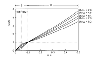
- the case where the potential ratio of the uniform deceleration electric fields B1 and B2 of the first stage and the second stage is 7: 3.
- the relationship between ion flight time and displacement was analyzed by simulation for several initial energies. The result is shown in FIG.
- the horizontal axis of the graph in FIG. 5 is the displacement from the starting point, and the vertical axis is the flight time.
- the potential shapes are displayed below.
- the free flight area A was divided into two equal parts for the forward path and the return path, and the overall length L was set to 1 [m].
- the reference potential is 3.5 [keV].
- the condition for smoothly connecting the electric field at the boundary between the deceleration region B and the reflection region C is that the following two conditions are satisfied on the boundary.
- Electric field continuity (ii) Electric field continuity is based on the first derivative of the potential.
- Electric field continuity is based on the second derivative of the potential.
- the first and second derivatives of the potential at the boundary viewed from the reflection region C side can be obtained from the inverse function x (U) as shown in equations (28) and (29), respectively.
- the potential inverse function x (U) is analytically given, the parameter conditions for the electric field ideal connection are analytically determined from the above two conditions.
- a state satisfying the above two conditions can be obtained by numerical calculation.
- Equation (3) shows the expressions of the first and second derivatives of x (u) required for calculation by u.
- the electric field strength U ′ (0) at the boundary viewed from the reflection region C side is expressed by the following equation (33).
- the electric field strength at the boundary viewed from the deceleration region B side is U / Ld because the electric field in front of it is a uniform deceleration electric field, and is equal to the value viewed from the reflection region C side. That is, in this case, the electric field continuity at the boundary between the deceleration region B and the reflection region C is satisfied.
- the parameter condition for the electric field ideal connection when the deceleration region B is composed of the two-stage uniform deceleration fields B1 and B2 is obtained.
- the potential distribution function of the reflection region C is as shown in the equation (3).
- the potential by the first uniform deceleration electric field B1 is U 1 and the potential by the second uniform deceleration electric field B2 is U 2 .
- the lengths of the uniform deceleration electric fields B1 and B2 at each stage are Ld 1 and Ld 2 , respectively.
- the length of the free flight space B3 is set to Lf using the ratio f to the length of the free flight region A.
- the potential distribution in the reflection region C is analytically obtained as the following equation (36).
- the ions fly in the free flight space B3 while being decelerated by the first-stage deceleration electric field B1, so that the ion flight time can be extended without increasing the size of the device, and a small, high-resolution device. It is advantageous to realize.
- the potential distribution in the acceleration region D is composed of a single-step uniform acceleration electric field and the deceleration region B is composed of a uniform deceleration electric field.
- the shape of the potential distribution at this time is shown in FIG.
- the length of the acceleration region D is La using the ratio a to the length of the free flight region A, and the maximum potential in the acceleration region D is U a .
- Other parameters are the same as in the above examples.
- the potential distribution in the acceleration region D is composed of a single-stage uniform acceleration electric field
- the deceleration region B is composed of two-stage uniform deceleration electric fields B1 and B2.
- the shape of the potential distribution at this time is shown in FIG.
- the parameters are the same as in the above examples.
- the potential distribution in the reflection region C is analytically obtained as the following equation (41). Similar to the above example, the variables and parameters are made dimensionless here. Further, the parameter condition for the electric field ideal connection at this time is expressed by the following equation (42).
- the deceleration region B is a single-stage uniform deceleration electric field and the two-stage uniform deceleration electric field.
- the same method is used. It is clear that the same result is used, that is, the time of flight of the ions is equal regardless of the energy difference.
- the ion optical system used here does not include the acceleration region D, and the deceleration region B consists of a two-stage uniform deceleration electric field.
- the reflectron is composed of a plurality of electrodes as shown in FIGS. 12 and 13 to be described later, with the electrode located at the boundary between the first-stage deceleration electric field B1 and the second-stage deceleration electric field B2 as a boundary. From the first electrode at the entrance of the reflectron to the electrode located at the boundary will be referred to as a front stage part, and all the subsequent electrodes (that is, including the reflection region C) will be referred to as a rear stage part. It is assumed that the optimum voltage value to be applied is obtained by theoretical calculation or simulation in each of the front stage part and the rear stage part, and the voltage value relative ratio of each electrode is calculated for each part.
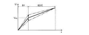
- FIG. 10 shows the voltage value applied to the foremost electrode of the front stage, that is, the voltage value at the inlet end of the first stage deceleration electric field B1, and the voltage applied to the backmost electrode of the rear stage.
- the value that is, the voltage value at the end of the reflection region C is virtually fixed, and the voltage value V adj at the boundary between the first stage deceleration electric field B1 and the second stage deceleration electric field B2 is changed from an ideal state.
- FIG. 11 shows the simulation results of the TOF peak when the voltage value V adj is the optimum value, when ⁇ 1% is changed from the optimum value, and when ⁇ 2% is changed from the optimum value.
- a peak having a shape that is almost the same as the optimum value is obtained with a change of ⁇ 1%.
- the peak hem shape is slightly deteriorated, but the peak half-value width can be maintained substantially equal to the optimum value.
- the performance determined by the peak half-value width such as mass resolution, it is considered that a deviation of about 5% from the theoretically optimum value is sufficiently acceptable.
- the maximum change from the straight line can be suppressed to a very small value depending on how the parameters are selected. If the maximum change amount is within the potential distribution deviation allowable range as described above, the potential distribution in the reflection region C can be approximated by a straight line, and the configuration of the apparatus is simplified and the cost is reduced as described later. Is advantageous.
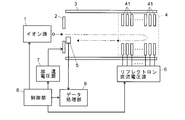
- FIG. 12 is a schematic configuration diagram of the TOFMS according to the present embodiment
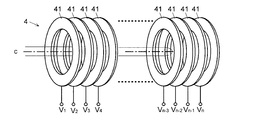
- FIG. 13 is a schematic perspective view of the reflectron 4 in FIG.
- the sample-derived ions generated by the ion source 1 are given initial energy by the electric field formed by the voltage applied from the acceleration voltage source 7 to the acceleration electrode 2, and are formed in the flight tube 3. It is thrown into the flight space.
- a reflectron 4 composed of a plurality of electrodes is disposed in the flight tube 3, and each ion is decelerated and reflected by an electric field formed by the reflectron 4.
- the ions that are reflected and returned reach the detector 5, and the detector 5 outputs a detection signal corresponding to the amount of ions that have reached.
- a predetermined voltage is applied to each electrode constituting the reflectron 4 from the reflectron DC voltage source 6, thereby forming an electrostatic field (DC electric field) having a predetermined potential shape in the space inside the reflectron 4.
- the control unit 8 controls the ion source 1, the acceleration voltage source 7, the reflectron DC voltage source 6, and the like. Further, the data processing unit 9 obtains ion acceleration timing information, that is, ion flight departure time information from the control unit 8, and uses this as a reference to measure the flight time based on the detection signal of each ion.
- ion acceleration timing information that is, ion flight departure time information from the control unit 8, and uses this as a reference to measure the flight time based on the detection signal of each ion.
- a mass spectrum is created by converting time to mass-to-charge ratio m / z.
- the reflectron 4 is configured by a plurality (n pieces) of ring-shaped electrodes 41 arranged along the central axis c.
- the DC voltages V 1 , V 2 ,..., V n applied from the reflectron DC voltage source 6 to the ring electrode 41 to predetermined values calculated in advance, the space surrounded by the ring electrode 41 is centered.
- a deceleration region B having one or more kinds of potential distributions and a reflection region C having a curved potential distribution are formed along the axis c to realize a reflectron in which the energy dependence of the flight time is removed.
- the voltage applied to each ring-shaped electrode 41 and the potential distribution of the electric field formed thereby are obtained by simulation calculation (analytical expression or numerical calculation). be able to. Therefore, if a desired potential distribution is determined as described above, a voltage value that realizes this can be obtained in advance by calculation, that is, at the design stage of the apparatus.
- each ring-shaped electrode 41 which comprises the reflectron 4 should just be the structure surrounding one space as a whole, and a specific form is not limited to this. That is, as viewed from the central axis c, the opening may not be circular, but may be oval, square, polygonal, etc., and one ring-shaped electrode is composed of a plurality of divided electrodes. But you can.
- each of the ring-shaped electrodes 41 is not given a voltage whose value can be adjusted from the reflectron DC voltage source 6, but a voltage divided by resistance using a ladder resistor circuit or the like. It is good also as a structure applied to each ring-shaped electrode 41. FIG. In that case, it is natural that the voltage applied to each ring electrode 41 can be adjusted by adjusting the resistance value of the ladder resistor circuit for resistance division, but in order to simplify the configuration and ensure high performance. It is desirable to align the values of a plurality of resistors constituting the ladder resistor circuit. When the potential distribution is linear, a ladder resistor circuit using resistors having the same value can be easily used.
- a uniform decelerating electric field can be formed by applying a resistance-divided voltage from a ladder resistor circuit using resistors having the same value to a plurality of electrodes arranged at equal intervals.
- the voltage obtained by dividing the resistance from the ladder resistor circuit using the resistor having the same value by appropriately adjusting the interval between the adjacent electrodes instead of being constant. Can be applied.
- the ladder resistor circuit using the same resistance without adjusting the electrode interval (as a constant interval). The voltage divided by resistance may be applied.
- the reflectron 4 is composed of a plurality of electrodes
- the deceleration region B is composed of a two-stage uniform deceleration electric field
- the equation (35) for electric field ideal connection An effective voltage value adjusting method when the condition is satisfied will be described.
- the optimum voltage value applied to each electrode is obtained by theoretical calculation or simulation at the rear stage (uniform deceleration electric field B2 and reflection region C) at the exit side, and each electrode is provided for each part. Assume that the relative voltage value ratio is calculated.
- the ion starting position position of the acceleration electrode 2
- the position of the detector 5 may be changed so that the observed half-value width of the TOF peak becomes the smallest (that is, the time spread for ions having the same mass-to-charge ratio is minimized). it can.
- changing the voltage value while maintaining the voltage relative ratios of the respective parts in this way means that the reduction ratio u 1 or u 2 of the first-stage uniform deceleration electric field B1 or the second-stage uniform deceleration electric field B2 is maintained.
- a change in u 1 or u 2 means a change in the dimensionless parameter d that gives the length of the deceleration electric field.
- the actual length Ld of the deceleration electric field determined by the parameter d and the length L of the free flight region A is fixed, so that d is actually set under the condition that Ld is constant. Therefore, L is changed substantially. That is, when the starting point of ions is fixed, the position of the detection surface that is theoretically optimal changes according to the change in the length L of the free flight region A.
- the position of the detection surface is fixed when the detector 5 is incorporated into the apparatus.
- the change in the voltage value applied to the electrode as described above causes a change in the half width of the TOF peak.
- the voltage value applied to the electrode as described above it is possible to adjust the half value width of the TOF peak to be the smallest.
- performance deteriorates due to variations in processing and assembly of members such as electrodes, and variations in the value of applied voltage.
- a ladder resistor circuit is used for voltage application, one to a few The performance can be improved only by adjusting the voltage value, which is a great advantage in simplifying the adjustment of the apparatus.
- the ion incident position and direction with respect to the reflectron 4 may be incident on the central axis c along the central axis c so that the forward and backward paths of the ions are on the same line.
- the ions may be incident at an angle so that the forward and backward paths of the ions do not overlap.
- FIG. 14 is a diagram showing another configuration example of the reflectron 4.
- a flat plate electrode 42 having an ion passage hole is arranged at the boundary of a uniform deceleration electric field to form a deceleration region B, and a plurality of ring electrodes 41 form a reflection region C.
- the deceleration region B is composed of one or more types of uniform deceleration electric fields, and an electric field having a curved potential distribution derived according to the potential shape of the deceleration region B is formed in the reflection region C.
- a forward pass hole and a return pass hole are provided at predetermined positions in the flat plate electrode 42 so that ions are incident at an angle with respect to the central axis c so that the reciprocal paths of the ions are different. ing.
- the position and shape of the hole at this time can be determined by ion trajectory simulation.
- one hole having a shape and a size that allows ions to pass when they reciprocate along different paths may be provided.
- the plate electrode 42 may be formed with one hole that passes through both the forward path and the return path.
- a ring electrode may be inserted into the space between the adjacent flat plate electrodes 42 for the purpose of improving the uniformity of the electric field.
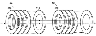
- FIG. 15 is a schematic view of a flight space configured to include two reflectrons in that case.
- the two reflectrons 4A and 4B correspond to the reflectron 4 shown in FIG.
- the two reflectrons 4A and 4B are arranged to face each other so that the boundary surfaces of the free flight area A on the side not in contact with the deceleration area B coincide. Ions are introduced from the outside of one of the two reflectrons 4A and 4B into the interior of the reflectrons 4A and 4B and the space between them along the central axis c.
- ions are incident along the central axis c from the outside of the reflectron 4A (left side in FIG. 15).
- the voltage applied to each ring electrode 41a of the reflectron 4A on the ion introduction side is set to a reference ground potential or a value adjusted so that an electric field suitable for ion introduction is formed.
- the state in which the voltage applied to the ring electrode 41a is in such a state is referred to as “off”.
- the ions introduced inside are reflected by the other reflectron 4B and before entering the deceleration region B of the ion introduction side reflectron 4A, as described above on each ring electrode 41a of the ion introduction side reflectron 4A.
- a predetermined voltage for operating as an energy-independent reflectron is applied, and ions are reflected also at the ion introduction side reflectron 4A.
- the state in which the voltage applied to the ring electrode 41a is in such a state is referred to as “on”.
- the ions are reciprocated between the two reflectrons 4A and 4B, thereby substantially trapping the ions in the flight space.
- the other reflectron 4B facing the ion introduction side is set as the ion discharge side, and the applied voltage to the ring electrode 41b of the reflectron 4B on the ion discharge side is set.
- ions are ejected outside the flight space (to the right in FIG. 15). Then, for example, ions are detected by a detector (not shown) provided outside.
- a detector not shown
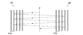
- ions reciprocate on substantially the same path between the two reflectrons 4A and 4B arranged opposite to each other, but multiple reflections may be performed so that the reciprocal paths of ions do not overlap. Good.
- An example of the ion path in that case is shown in FIG. In FIG. 16, the dotted line P indicates the boundary surface of the free flight region A on the side that is not in contact with the deceleration region B in the two reflectrons 4A and 4B.
- the position gradually shifts in a direction perpendicular to the central axes of the reflectrons 4A and 4B. Therefore, the number of reciprocations, that is, the flight distance is determined according to the angle with respect to the central axis c when the ions are incident on the reflectron 4A on the ion introduction side.
- an ion optical element such as a lens may be inserted into the free flight region A for the purpose of suppressing the divergence of the ion trajectory. Further, it is possible to realize the multiple reflection configuration shown in FIG. 16 by using two reflectrons having the configuration shown in FIG.
- an ion non-destructive detector is installed in the free flight region A between the two reflectrons 4A and 4B. It is also possible to perform non-destructive observation of the intensity of ions passing through and analyze the motion period of ions of each mass-to-charge ratio from the observation signal by, for example, Fourier transform, etc.
- ions in flight in the free flight region between the two reflectrons 4A and 4B.
- a part of the free flight region A between the reflectrons 4A and 4B is irradiated with an electron beam so as to cross the ion flight path, and ions are captured and dissociated by the action of the electron beam. Ions may be generated, and the product ions may further fly to perform mass analysis.
- a part of the free flight region A between the reflectrons 4A and 4B is irradiated with a reactive ion beam so as to cross the ion flight path, and the ions are electron-transfer dissociated by the action of the ion beam.
- Product ions may be generated, and the product ions may be further flighted for mass analysis.
- the type of the ion source 1 is not particularly mentioned.
- the MALDI ion source or matrix is used as the ion source 1.
- An LDI ion source that does not use can be used.
- the ion source 1 is an EI ion source or a CI ion source, and a GC-MS configuration in which a gas chromatograph is connected in front of the TOFMS can also be used.
- the ion source 1 is a so-called atmospheric pressure ion source such as an ESI ion source, an APCI ion source, an APPI ion source, etc., and an LC- that has a liquid chromatograph connected in front of this TOFMS.
- An MS configuration may also be used.
- ions extracted from the ion source are not accelerated and put into the flight space in the flight tube 3, but ions are put into a three-dimensional quadrupole or linear ion trap. It is good also as a structure which once captures and performs ion cooling, assigns initial energy to ion all at once, and sends it to flight space.
- ion selection and collision-induced dissociation may be performed in the ion trap, and product ions for a specific precursor ion may be sent to the flight space for mass analysis with high resolution.
- a time-of-flight mass separator using one or two reflectrons configured as described above is used for both precursor selection and mass analysis of product ions. You may make it use.
Landscapes
- Chemical & Material Sciences (AREA)
- Analytical Chemistry (AREA)
- Other Investigation Or Analysis Of Materials By Electrical Means (AREA)
- Electron Tubes For Measurement (AREA)
Abstract
L'invention porte sur un spectromètre de masse (MS) à temps de vol (TOF) équipé d'un réflectron idéal qui assure un haut degré de liberté dans la conception et dans lequel le temps de vol d'ions ayant un rapport m/z identique ne dépend pas de leur énergie. Le champ électrique formé par le réflectron est virtuellement divisé en une région de décélération (B) dans laquelle des ions sont décélérés et une région de réflexion (C) dans laquelle des ions sont réfléchis, et la région de décélération est déterminée par une ou plusieurs distributions de potentiel, telles qu'un champ électrique de décélération homogène de premier étage et un champ électrique de décélération homogène de second étage, le long de l'axe central. D'autre part, en ce qui concerne la région de réflexion, des ions ayant un certain rapport masse sur charge (m/z) partant d'une position prescrite selon les paramètres de la région de décélération sont guidés vers la région de réflexion par l'intermédiaire d'une région de vol libre (A) et de la région de décélération. La distribution de potentiel de ces champs électriques est déterminée par une équation analytique ou des calculs numériques de manière qu'un temps de vol pour faire demi-tour dans la région de réflexion et revenir à la position d'origine soit le même que le temps de vol pour des ions ayant le rapport masse sur charge identique ayant une trajectoire de retour au niveau de la frontière entre la région de décélération et la région de réflexion ou au niveau d'une position prescrite à l'intérieur de la région de décélération.
Priority Applications (4)
| Application Number | Priority Date | Filing Date | Title |
|---|---|---|---|
| US13/821,202 US8664592B2 (en) | 2010-09-08 | 2011-09-06 | Time-of-flight mass spectrometer |
| EP11823569.6A EP2615623B1 (fr) | 2010-09-08 | 2011-09-06 | Spectromètre de masse à temps de vol |
| JP2012532983A JP5482905B2 (ja) | 2010-09-08 | 2011-09-06 | 飛行時間型質量分析装置 |
| CN201180053862.5A CN103201821B (zh) | 2010-09-08 | 2011-09-06 | 飞行时间型质量分析装置 |
Applications Claiming Priority (2)
| Application Number | Priority Date | Filing Date | Title |
|---|---|---|---|
| JP2010201261 | 2010-09-08 | ||
| JP2010-201261 | 2010-09-08 |
Publications (1)
| Publication Number | Publication Date |
|---|---|
| WO2012033094A1 true WO2012033094A1 (fr) | 2012-03-15 |
Family
ID=45810692
Family Applications (1)
| Application Number | Title | Priority Date | Filing Date |
|---|---|---|---|
| PCT/JP2011/070270 Ceased WO2012033094A1 (fr) | 2010-09-08 | 2011-09-06 | Spectromètre de masse à temps de vol |
Country Status (5)
| Country | Link |
|---|---|
| US (1) | US8664592B2 (fr) |
| EP (1) | EP2615623B1 (fr) |
| JP (1) | JP5482905B2 (fr) |
| CN (1) | CN103201821B (fr) |
| WO (1) | WO2012033094A1 (fr) |
Cited By (4)
| Publication number | Priority date | Publication date | Assignee | Title |
|---|---|---|---|---|
| WO2014057777A1 (fr) * | 2012-10-10 | 2014-04-17 | 株式会社島津製作所 | Spectromètre de masse à temps de vol |
| JP2015185306A (ja) * | 2014-03-24 | 2015-10-22 | 株式会社島津製作所 | 飛行時間型質量分析装置 |
| WO2018109920A1 (fr) * | 2016-12-16 | 2018-06-21 | 株式会社島津製作所 | Dispositif de spectrométrie de masse |
| CN115952611A (zh) * | 2022-09-28 | 2023-04-11 | 上海交通大学 | 一种飞行时间质谱仪的参数设计方法 |
Families Citing this family (10)
| Publication number | Priority date | Publication date | Assignee | Title |
|---|---|---|---|---|
| GB201119059D0 (en) | 2011-11-04 | 2011-12-21 | Micromass Ltd | Improvements to tof mass spectrometers using linear accelerator devices |
| JP5993677B2 (ja) * | 2012-09-14 | 2016-09-14 | 日本電子株式会社 | 飛行時間型質量分析計及び飛行時間型質量分析計の制御方法 |
| US11081331B2 (en) | 2015-10-28 | 2021-08-03 | Duke University | Mass spectrometers having segmented electrodes and associated methods |
| GB201520540D0 (en) * | 2015-11-23 | 2016-01-06 | Micromass Uk Ltd And Leco Corp | Improved ion mirror and ion-optical lens for imaging |
| US10283335B2 (en) * | 2016-06-03 | 2019-05-07 | e-MSion, Inc. | Reflectron-electromagnetostatic cell for ECD fragmentation in mass spectrometers |
| GB2568354B (en) * | 2017-09-28 | 2022-08-10 | Bruker Daltonics Gmbh & Co Kg | Wide-range high mass resolution in reflector time-of-flight mass spectrometers |
| CN110445174B (zh) * | 2019-08-12 | 2022-04-19 | 电子科技大学 | 一种考虑随机风速影响的风电场系统暂态稳定性评估方法 |
| CN112799120B (zh) * | 2019-11-13 | 2024-03-22 | 中国科学院国家空间科学中心 | 一种离子和电子同步测量的双通道静电分析器 |
| CN116822248B (zh) * | 2023-08-23 | 2023-11-17 | 杭州谱育科技发展有限公司 | 飞行时间质谱装置的参数设计方法 |
| CN120805825B (zh) * | 2025-09-08 | 2025-11-14 | 恒泰柯半导体(上海)有限公司 | 减少二极管反向漏电流的方法及系统 |
Citations (5)
| Publication number | Priority date | Publication date | Assignee | Title |
|---|---|---|---|---|
| JPS60119067A (ja) * | 1983-11-30 | 1985-06-26 | Shimadzu Corp | 飛行時間型質量分析装置 |
| JPH08507640A (ja) * | 1993-03-04 | 1996-08-13 | コア テクノロジー リミテッド | イオン銃及びこれを使用する質量分析計 |
| JP2002532845A (ja) * | 1998-12-17 | 2002-10-02 | ジェー・イー・オー・エル・ユー・エス・エー,インコーポレーテッド | 衝突誘導解離を使用する分子構造分析用のインライン反射飛翔時間型質量分析計 |
| JP2004500683A (ja) * | 1999-06-11 | 2004-01-08 | ザ ジョンズ ホプキンス ユニバーシティ | 飛行時間型質量分析計の質量相関パルス引出しを行なう方法及び装置 |
| JP2006196216A (ja) * | 2005-01-11 | 2006-07-27 | Jeol Ltd | タンデム飛行時間型質量分析装置 |
Family Cites Families (13)
| Publication number | Priority date | Publication date | Assignee | Title |
|---|---|---|---|---|
| JPS59123154A (ja) | 1982-12-29 | 1984-07-16 | Shimadzu Corp | 飛行時間型質量分析装置 |
| DE3524536A1 (de) * | 1985-07-10 | 1987-01-22 | Bruker Analytische Messtechnik | Flugzeit-massenspektrometer mit einem ionenreflektor |
| US5160840A (en) * | 1991-10-25 | 1992-11-03 | Vestal Marvin L | Time-of-flight analyzer and method |
| WO1999027560A2 (fr) * | 1997-11-24 | 1999-06-03 | The Johns-Hopkins University | Procede et appareil permettant de corriger la vitesse initiale d'ions dans un spectrometre de masse a temps de vol a reflectron |
| GB0006046D0 (en) * | 2000-03-13 | 2000-05-03 | Univ Warwick | Time of flight mass spectrometry apparatus |
| GB2403063A (en) * | 2003-06-21 | 2004-12-22 | Anatoli Nicolai Verentchikov | Time of flight mass spectrometer employing a plurality of lenses focussing an ion beam in shift direction |
| US7199363B2 (en) * | 2003-10-14 | 2007-04-03 | Micromass Uk Limited | Mass spectrometer |
| US7148472B2 (en) * | 2004-02-28 | 2006-12-12 | Ngx, Inc. | Aerosol mass spectrometer for operation in a high-duty mode and method of mass-spectrometry |
| US7071466B2 (en) * | 2004-04-19 | 2006-07-04 | Ngx, Inc. | Mass spectrometry system for continuous control of environment |
| US7589319B2 (en) * | 2007-05-01 | 2009-09-15 | Virgin Instruments Corporation | Reflector TOF with high resolution and mass accuracy for peptides and small molecules |
| CN101800151A (zh) * | 2010-02-24 | 2010-08-11 | 方向 | 非对称场反射式飞行时间质谱仪 |
| WO2012005561A2 (fr) * | 2010-07-09 | 2012-01-12 | Saparqaliyev Aldan Asanovich | Procédé de spectrométrie de masse et dispositif de sa mise en oeuvre |
| GB2484136B (en) * | 2010-10-01 | 2015-09-16 | Thermo Fisher Scient Bremen | Method and apparatus for improving the throughput of a charged particle analysis system |
-
2011
- 2011-09-06 WO PCT/JP2011/070270 patent/WO2012033094A1/fr not_active Ceased
- 2011-09-06 CN CN201180053862.5A patent/CN103201821B/zh active Active
- 2011-09-06 JP JP2012532983A patent/JP5482905B2/ja active Active
- 2011-09-06 EP EP11823569.6A patent/EP2615623B1/fr active Active
- 2011-09-06 US US13/821,202 patent/US8664592B2/en active Active
Patent Citations (5)
| Publication number | Priority date | Publication date | Assignee | Title |
|---|---|---|---|---|
| JPS60119067A (ja) * | 1983-11-30 | 1985-06-26 | Shimadzu Corp | 飛行時間型質量分析装置 |
| JPH08507640A (ja) * | 1993-03-04 | 1996-08-13 | コア テクノロジー リミテッド | イオン銃及びこれを使用する質量分析計 |
| JP2002532845A (ja) * | 1998-12-17 | 2002-10-02 | ジェー・イー・オー・エル・ユー・エス・エー,インコーポレーテッド | 衝突誘導解離を使用する分子構造分析用のインライン反射飛翔時間型質量分析計 |
| JP2004500683A (ja) * | 1999-06-11 | 2004-01-08 | ザ ジョンズ ホプキンス ユニバーシティ | 飛行時間型質量分析計の質量相関パルス引出しを行なう方法及び装置 |
| JP2006196216A (ja) * | 2005-01-11 | 2006-07-27 | Jeol Ltd | タンデム飛行時間型質量分析装置 |
Cited By (5)
| Publication number | Priority date | Publication date | Assignee | Title |
|---|---|---|---|---|
| WO2014057777A1 (fr) * | 2012-10-10 | 2014-04-17 | 株式会社島津製作所 | Spectromètre de masse à temps de vol |
| JP5862791B2 (ja) * | 2012-10-10 | 2016-02-16 | 株式会社島津製作所 | 飛行時間型質量分析装置 |
| JP2015185306A (ja) * | 2014-03-24 | 2015-10-22 | 株式会社島津製作所 | 飛行時間型質量分析装置 |
| WO2018109920A1 (fr) * | 2016-12-16 | 2018-06-21 | 株式会社島津製作所 | Dispositif de spectrométrie de masse |
| CN115952611A (zh) * | 2022-09-28 | 2023-04-11 | 上海交通大学 | 一种飞行时间质谱仪的参数设计方法 |
Also Published As
| Publication number | Publication date |
|---|---|
| CN103201821A (zh) | 2013-07-10 |
| JPWO2012033094A1 (ja) | 2014-01-20 |
| EP2615623A4 (fr) | 2015-08-12 |
| US20130168547A1 (en) | 2013-07-04 |
| EP2615623B1 (fr) | 2021-06-16 |
| JP5482905B2 (ja) | 2014-05-07 |
| EP2615623A1 (fr) | 2013-07-17 |
| CN103201821B (zh) | 2015-08-26 |
| US8664592B2 (en) | 2014-03-04 |
Similar Documents
| Publication | Publication Date | Title |
|---|---|---|
| JP5482905B2 (ja) | 飛行時間型質量分析装置 | |
| JP6287419B2 (ja) | 飛行時間型質量分析装置 | |
| RU2458427C2 (ru) | Времяпролетный масс-анализатор с многократными отражениями и времяпролетный масс-спектрометр, включающий в себя данный масс- анализатор | |
| JP6152113B2 (ja) | 加速器デバイスを備える質量分析計及び質量分析方法 | |
| JP6907226B2 (ja) | 飛行時間質量分析法のためのマルチモードイオンミラープリズム及びエネルギーフィルタリング装置及びシステム | |
| US9281175B2 (en) | First and second order focusing using field free regions in time-of-flight | |
| US9412578B2 (en) | Charged particle analysers and methods of separating charged particles | |
| US9196469B2 (en) | Constraining arcuate divergence in an ion mirror mass analyser | |
| JP5628165B2 (ja) | 疑似平面多重反射飛行時間型質量分析計 | |
| JP5870384B2 (ja) | 直交加速同軸円筒飛行時間型質量分析器 | |
| WO2020002940A1 (fr) | Spectromètre de masse à plusieurs passages avec cycle de service élevé | |
| US7355168B2 (en) | Time of flight mass spectrometer | |
| GB2477007A (en) | Electrostatic trap mass spectrometer | |
| WO2018109920A1 (fr) | Dispositif de spectrométrie de masse | |
| GB2491305A (en) | A mass spectrometer arranged to analyze positive and negative ions | |
| CN103907171A (zh) | 静电离子镜 | |
| CA2624926A1 (fr) | Spectrometre de masse de temps de vol multireflechissant avec acceleration orthogonale | |
| JP6292319B2 (ja) | 飛行時間型質量分析装置 | |
| JP3797200B2 (ja) | 飛行時間型質量分析装置 | |
| JP2026504416A (ja) | 多重反射型tof質量分析 | |
| JP5243977B2 (ja) | 垂直加速型飛行時間型質量分析計 | |
| JP5946881B2 (ja) | 疑似平面多重反射飛行時間型質量分析計 | |
| JP2001229875A (ja) | 垂直加速型飛行時間型質量分析装置 | |
| US20160093483A1 (en) | Method of Generating Electric Field for Manipulating Charged Particles |
Legal Events
| Date | Code | Title | Description |
|---|---|---|---|
| 121 | Ep: the epo has been informed by wipo that ep was designated in this application |
Ref document number: 11823569 Country of ref document: EP Kind code of ref document: A1 |
|
| WWE | Wipo information: entry into national phase |
Ref document number: 2012532983 Country of ref document: JP |
|
| WWE | Wipo information: entry into national phase |
Ref document number: 13821202 Country of ref document: US |
|
| NENP | Non-entry into the national phase |
Ref country code: DE |
|
| WWE | Wipo information: entry into national phase |
Ref document number: 2011823569 Country of ref document: EP |