WO2012036190A1 - Bloc-batterie et véhicule électrique équipé du bloc-batterie - Google Patents
Bloc-batterie et véhicule électrique équipé du bloc-batterie Download PDFInfo
- Publication number
- WO2012036190A1 WO2012036190A1 PCT/JP2011/070952 JP2011070952W WO2012036190A1 WO 2012036190 A1 WO2012036190 A1 WO 2012036190A1 JP 2011070952 W JP2011070952 W JP 2011070952W WO 2012036190 A1 WO2012036190 A1 WO 2012036190A1
- Authority
- WO
- WIPO (PCT)
- Prior art keywords
- flange portion
- piece
- cover
- lower flange
- battery pack
- Prior art date
- Legal status (The legal status is an assumption and is not a legal conclusion. Google has not performed a legal analysis and makes no representation as to the accuracy of the status listed.)
- Ceased
Links
Images



Classifications
-
- B—PERFORMING OPERATIONS; TRANSPORTING
- B60—VEHICLES IN GENERAL
- B60K—ARRANGEMENT OR MOUNTING OF PROPULSION UNITS OR OF TRANSMISSIONS IN VEHICLES; ARRANGEMENT OR MOUNTING OF PLURAL DIVERSE PRIME-MOVERS IN VEHICLES; AUXILIARY DRIVES FOR VEHICLES; INSTRUMENTATION OR DASHBOARDS FOR VEHICLES; ARRANGEMENTS IN CONNECTION WITH COOLING, AIR INTAKE, GAS EXHAUST OR FUEL SUPPLY OF PROPULSION UNITS IN VEHICLES
- B60K1/00—Arrangement or mounting of electrical propulsion units
- B60K1/04—Arrangement or mounting of electrical propulsion units of the electric storage means for propulsion
-
- B—PERFORMING OPERATIONS; TRANSPORTING
- B60—VEHICLES IN GENERAL
- B60L—PROPULSION OF ELECTRICALLY-PROPELLED VEHICLES; SUPPLYING ELECTRIC POWER FOR AUXILIARY EQUIPMENT OF ELECTRICALLY-PROPELLED VEHICLES; ELECTRODYNAMIC BRAKE SYSTEMS FOR VEHICLES IN GENERAL; MAGNETIC SUSPENSION OR LEVITATION FOR VEHICLES; MONITORING OPERATING VARIABLES OF ELECTRICALLY-PROPELLED VEHICLES; ELECTRIC SAFETY DEVICES FOR ELECTRICALLY-PROPELLED VEHICLES
- B60L50/00—Electric propulsion with power supplied within the vehicle
- B60L50/50—Electric propulsion with power supplied within the vehicle using propulsion power supplied by batteries or fuel cells
- B60L50/60—Electric propulsion with power supplied within the vehicle using propulsion power supplied by batteries or fuel cells using power supplied by batteries
- B60L50/64—Constructional details of batteries specially adapted for electric vehicles
-
- H—ELECTRICITY
- H01—ELECTRIC ELEMENTS
- H01M—PROCESSES OR MEANS, e.g. BATTERIES, FOR THE DIRECT CONVERSION OF CHEMICAL ENERGY INTO ELECTRICAL ENERGY
- H01M50/00—Constructional details or processes of manufacture of the non-active parts of electrochemical cells other than fuel cells, e.g. hybrid cells
- H01M50/20—Mountings; Secondary casings or frames; Racks, modules or packs; Suspension devices; Shock absorbers; Transport or carrying devices; Holders
- H01M50/271—Lids or covers for the racks or secondary casings
-
- B—PERFORMING OPERATIONS; TRANSPORTING
- B60—VEHICLES IN GENERAL
- B60K—ARRANGEMENT OR MOUNTING OF PROPULSION UNITS OR OF TRANSMISSIONS IN VEHICLES; ARRANGEMENT OR MOUNTING OF PLURAL DIVERSE PRIME-MOVERS IN VEHICLES; AUXILIARY DRIVES FOR VEHICLES; INSTRUMENTATION OR DASHBOARDS FOR VEHICLES; ARRANGEMENTS IN CONNECTION WITH COOLING, AIR INTAKE, GAS EXHAUST OR FUEL SUPPLY OF PROPULSION UNITS IN VEHICLES
- B60K11/00—Arrangement in connection with cooling of propulsion units
- B60K11/06—Arrangement in connection with cooling of propulsion units with air cooling
-
- B—PERFORMING OPERATIONS; TRANSPORTING
- B60—VEHICLES IN GENERAL
- B60K—ARRANGEMENT OR MOUNTING OF PROPULSION UNITS OR OF TRANSMISSIONS IN VEHICLES; ARRANGEMENT OR MOUNTING OF PLURAL DIVERSE PRIME-MOVERS IN VEHICLES; AUXILIARY DRIVES FOR VEHICLES; INSTRUMENTATION OR DASHBOARDS FOR VEHICLES; ARRANGEMENTS IN CONNECTION WITH COOLING, AIR INTAKE, GAS EXHAUST OR FUEL SUPPLY OF PROPULSION UNITS IN VEHICLES
- B60K1/00—Arrangement or mounting of electrical propulsion units
- B60K2001/003—Arrangement or mounting of electrical propulsion units with means for cooling the electrical propulsion units
- B60K2001/005—Arrangement or mounting of electrical propulsion units with means for cooling the electrical propulsion units the electric storage means
-
- B—PERFORMING OPERATIONS; TRANSPORTING
- B60—VEHICLES IN GENERAL
- B60K—ARRANGEMENT OR MOUNTING OF PROPULSION UNITS OR OF TRANSMISSIONS IN VEHICLES; ARRANGEMENT OR MOUNTING OF PLURAL DIVERSE PRIME-MOVERS IN VEHICLES; AUXILIARY DRIVES FOR VEHICLES; INSTRUMENTATION OR DASHBOARDS FOR VEHICLES; ARRANGEMENTS IN CONNECTION WITH COOLING, AIR INTAKE, GAS EXHAUST OR FUEL SUPPLY OF PROPULSION UNITS IN VEHICLES
- B60K1/00—Arrangement or mounting of electrical propulsion units
- B60K1/04—Arrangement or mounting of electrical propulsion units of the electric storage means for propulsion
- B60K2001/0405—Arrangement or mounting of electrical propulsion units of the electric storage means for propulsion characterised by their position
- B60K2001/0438—Arrangement under the floor
-
- H—ELECTRICITY
- H01—ELECTRIC ELEMENTS
- H01M—PROCESSES OR MEANS, e.g. BATTERIES, FOR THE DIRECT CONVERSION OF CHEMICAL ENERGY INTO ELECTRICAL ENERGY
- H01M10/00—Secondary cells; Manufacture thereof
- H01M10/60—Heating or cooling; Temperature control
- H01M10/61—Types of temperature control
- H01M10/613—Cooling or keeping cold
-
- H—ELECTRICITY
- H01—ELECTRIC ELEMENTS
- H01M—PROCESSES OR MEANS, e.g. BATTERIES, FOR THE DIRECT CONVERSION OF CHEMICAL ENERGY INTO ELECTRICAL ENERGY
- H01M10/00—Secondary cells; Manufacture thereof
- H01M10/60—Heating or cooling; Temperature control
- H01M10/62—Heating or cooling; Temperature control specially adapted for specific applications
- H01M10/625—Vehicles
-
- H—ELECTRICITY
- H01—ELECTRIC ELEMENTS
- H01M—PROCESSES OR MEANS, e.g. BATTERIES, FOR THE DIRECT CONVERSION OF CHEMICAL ENERGY INTO ELECTRICAL ENERGY
- H01M10/00—Secondary cells; Manufacture thereof
- H01M10/60—Heating or cooling; Temperature control
- H01M10/65—Means for temperature control structurally associated with the cells
- H01M10/656—Means for temperature control structurally associated with the cells characterised by the type of heat-exchange fluid
- H01M10/6561—Gases
- H01M10/6563—Gases with forced flow, e.g. by blowers
-
- H—ELECTRICITY
- H01—ELECTRIC ELEMENTS
- H01M—PROCESSES OR MEANS, e.g. BATTERIES, FOR THE DIRECT CONVERSION OF CHEMICAL ENERGY INTO ELECTRICAL ENERGY
- H01M2220/00—Batteries for particular applications
- H01M2220/20—Batteries in motive systems, e.g. vehicle, ship, plane
-
- H—ELECTRICITY
- H01—ELECTRIC ELEMENTS
- H01M—PROCESSES OR MEANS, e.g. BATTERIES, FOR THE DIRECT CONVERSION OF CHEMICAL ENERGY INTO ELECTRICAL ENERGY
- H01M50/00—Constructional details or processes of manufacture of the non-active parts of electrochemical cells other than fuel cells, e.g. hybrid cells
- H01M50/20—Mountings; Secondary casings or frames; Racks, modules or packs; Suspension devices; Shock absorbers; Transport or carrying devices; Holders
- H01M50/204—Racks, modules or packs for multiple batteries or multiple cells
- H01M50/207—Racks, modules or packs for multiple batteries or multiple cells characterised by their shape
- H01M50/209—Racks, modules or packs for multiple batteries or multiple cells characterised by their shape adapted for prismatic or rectangular cells
-
- Y—GENERAL TAGGING OF NEW TECHNOLOGICAL DEVELOPMENTS; GENERAL TAGGING OF CROSS-SECTIONAL TECHNOLOGIES SPANNING OVER SEVERAL SECTIONS OF THE IPC; TECHNICAL SUBJECTS COVERED BY FORMER USPC CROSS-REFERENCE ART COLLECTIONS [XRACs] AND DIGESTS
- Y02—TECHNOLOGIES OR APPLICATIONS FOR MITIGATION OR ADAPTATION AGAINST CLIMATE CHANGE
- Y02E—REDUCTION OF GREENHOUSE GAS [GHG] EMISSIONS, RELATED TO ENERGY GENERATION, TRANSMISSION OR DISTRIBUTION
- Y02E60/00—Enabling technologies; Technologies with a potential or indirect contribution to GHG emissions mitigation
- Y02E60/10—Energy storage using batteries
-
- Y—GENERAL TAGGING OF NEW TECHNOLOGICAL DEVELOPMENTS; GENERAL TAGGING OF CROSS-SECTIONAL TECHNOLOGIES SPANNING OVER SEVERAL SECTIONS OF THE IPC; TECHNICAL SUBJECTS COVERED BY FORMER USPC CROSS-REFERENCE ART COLLECTIONS [XRACs] AND DIGESTS
- Y02—TECHNOLOGIES OR APPLICATIONS FOR MITIGATION OR ADAPTATION AGAINST CLIMATE CHANGE
- Y02T—CLIMATE CHANGE MITIGATION TECHNOLOGIES RELATED TO TRANSPORTATION
- Y02T10/00—Road transport of goods or passengers
- Y02T10/60—Other road transportation technologies with climate change mitigation effect
- Y02T10/70—Energy storage systems for electromobility, e.g. batteries
-
- Y—GENERAL TAGGING OF NEW TECHNOLOGICAL DEVELOPMENTS; GENERAL TAGGING OF CROSS-SECTIONAL TECHNOLOGIES SPANNING OVER SEVERAL SECTIONS OF THE IPC; TECHNICAL SUBJECTS COVERED BY FORMER USPC CROSS-REFERENCE ART COLLECTIONS [XRACs] AND DIGESTS
- Y10—TECHNICAL SUBJECTS COVERED BY FORMER USPC
- Y10S—TECHNICAL SUBJECTS COVERED BY FORMER USPC CROSS-REFERENCE ART COLLECTIONS [XRACs] AND DIGESTS
- Y10S903/00—Hybrid electric vehicles, HEVS
- Y10S903/902—Prime movers comprising electrical and internal combustion motors
- Y10S903/903—Prime movers comprising electrical and internal combustion motors having energy storing means, e.g. battery, capacitor
- Y10S903/904—Component specially adapted for hev
- Y10S903/907—Electricity storage, e.g. battery, capacitor
Definitions
- the present invention relates to a battery pack mounted on a hybrid electric vehicle (HEV) or an electric vehicle (EV).
- HEV hybrid electric vehicle
- EV electric vehicle
- the present invention also relates to an electric vehicle including the battery pack.
- an electric vehicle that do not emit CO 2 is becoming popular.
- An electric vehicle is equipped with a battery pack as an energy supply source for supplying energy to a drive motor and other electric systems.
- the battery pack includes a plurality of battery modules and a packaging case that houses the plurality of battery modules.
- Each battery module is a module in which a plurality of single cells are electrically connected and packaged together. That is, each battery module is an assembled battery composed of a plurality of single cells.
- the packaging case includes a tray on which the battery module is disposed and a cover that covers the battery module on the tray.
- the tray includes a bottom part in which a plurality of battery modules are arranged in a matrix in a plan view (a state in which the battery modules are aligned vertically and horizontally in a plan view), a lower peripheral wall part standing from the outer periphery of the bottom part, and the lower peripheral wall part And a lower flange portion extending outward from the upper end of the.
- the cover includes a top portion having a shape corresponding to the open portion of the tray, an upper peripheral wall portion depending from the outer periphery of the top portion, and an upper flange portion extending outward from the lower end of the upper peripheral wall portion.
- the open portion of the tray in which a plurality of battery modules are arranged on the bottom is covered with a cover, and bolts are inserted into the overlapping lower and upper flange portions, and nuts are screwed into the bolts. And the cover are fastened. Accordingly, the lower flange portion of the tray and the upper flange portion of the cover are in surface contact with each other, and the internal space of the packaging case that houses the battery module becomes liquid-tight.
- This battery pack is attached to the bottom of the electric vehicle. That is, the battery pack mounted on the electric vehicle has a very large overall weight and size due to the necessity of securing electric capacity. Therefore, from the viewpoint of running stability and arrangement of other configurations, It arrange
- the battery pack mounted on the electric vehicle is disposed at the bottom of the vehicle as described above, moisture is likely to adhere to the outer surface of the packaging case due to the water rebound during car washing or traveling. Therefore, it is necessary to sufficiently secure the liquid tightness between the tray and the cover (between the lower flange portion and the upper flange portion).
- the conventional battery pack makes the inner space of the packaging case liquid-tight by bringing the lower flange portion and the upper flange portion into surface contact. Therefore, when the pressure of the liquid applied to the packaging case is high, moisture may enter the internal space of the packaging case from between the lower flange portion and the upper flange portion.
- washing liquid water or liquid detergent
- washing liquid water or liquid detergent
- the high-pressure washing liquid is applied to the underbody of the electric vehicle or the bottom of the vehicle body.
- cleaning liquid may enter the interior space of the packaging case from between the lower flange portion and the upper flange portion, and the cleaning liquid may cause a short circuit or the like to damage the entire battery module or the single cell.
- the conventional battery pack has a problem that the cover attaching / detaching work accompanying the inspection or replacement of the battery module or the single battery is complicated. That is, in the conventional battery pack, the tray and the cover are fastened using bolts and nuts, but when fastening the tray and the cover, a plurality of locations (a plurality of points set around the tray and the cover) are used. Nut must be supplied to the fastening position), and when removing the cover from the tray, the nuts arranged at a plurality of locations must be collected. Therefore, the conventional battery pack has a problem that a very complicated operation must be performed when the cover is attached or detached in accordance with inspection or replacement of the battery module or the like.
- the present invention allows liquid such as water and cleaning liquid adhering to the outer surface of the packaging case constituted by the tray and the cover to enter the interior space of the packaging case from between the tray and the cover. It is an object of the present invention to provide a battery pack and an electric vehicle equipped with the battery pack that can reliably prevent this, and can eliminate the complexity of the work of attaching and detaching the cover to the tray.
- the battery pack according to the present invention is One or more cells, A packaging case that houses the one or more cells,
- the packaging case is A tray in which the unit cells are disposed, and a tray having a lower flange portion; A cover that covers the unit cells on the tray, and includes an upper flange portion, and the lower flange portion and the upper flange portion overlap in a state where the unit cells on the tray are covered with the cover.
- Edge cover that covers the entire circumference or substantially the entire circumference of the lower flange portion and the upper flange portion that overlap each other from the outside,
- the edge cover is A first piece facing the lower flange portion;
- a connecting portion that connects the base ends of the first piece and the second piece;
- a plurality of female screw portions are provided on either the first piece or the second piece,
- a screw insertion hole is provided in either the first piece or the second piece, the lower flange portion, and the upper flange portion for inserting a male screw member in accordance with the arrangement of the female screw portion. It is done.
- a nut is fixed on the outer surface on the opposite side of the surface facing the lower flange portion or the upper flange portion of either the first piece or the second piece.
- the screw hole of each nut may constitute the female screw portion.
- a sealing material may be interposed between the lower flange portion and the upper flange portion.
- the female screw portion is closed on either side of the first piece or the second piece on the side opposite to the surface facing the lower flange portion or the upper flange portion.
- it may be formed in a non-penetrating state.
- the lower flange portion and the upper flange portion have a frame shape having a square shape in plan view, and the edge cover covers a side portion of the lower flange portion and the upper flange portion. And a split cover that covers corners of the lower flange portion and the upper flange portion.
- the adjacent divided covers can be arranged so that the end portions are close to each other or overlap each other.
- the adjacent divided covers are arranged so that the first piece and the second piece of one divided cover cover the end portions of the first piece and the second piece of the other divided cover from the outside. Can be done.
- the packaging case may be configured to be attached to or attached to the bottom of an electric vehicle.
- the electric vehicle according to the present invention includes any one of the above battery packs.
- FIG. 1 is an overall perspective view of a battery pack according to an embodiment of the present invention.
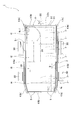
- FIG. 2 is an overall plan view of the battery pack according to the embodiment.
- FIG. 3 is an exploded perspective view of the battery pack according to the embodiment, and shows an exploded perspective view in a state in which a cooling fan is omitted.
- FIG. 4 is a partially enlarged cross-sectional view of the battery pack according to the embodiment.
- FIG. 4A is an edge cover (only the first divided cover or the second divided cover) that overlaps the lower flange portion and the upper flange portion.
- FIG. 5 is a cross-sectional view for explaining the liquid tightness of the battery pack according to the embodiment.
- FIG. 5A is an edge cover (first divided cover or second cover) that overlaps the lower flange portion and the upper flange portion.
- (B) shows an edge cover (first divided cover or second divided cover) covering the lower flange portion and the upper flange portion which are overlapped with each other. A state in which a high-pressure liquid (cleaning liquid) is sprayed on a portion where a cover is covered with another edge cover (third divided cover) is shown.
- cleaning liquid cleaning liquid
- Such a battery pack is mounted on an electric vehicle (EV) which is an electric vehicle.
- EV electric vehicle
- FIGS. 1 to 3 a plurality of battery modules 2,... And a packaging for housing the battery modules 2,. Case 3 is provided.
- the battery pack 1 according to the present embodiment is characterized by a packaging case 3 and an edge cover 4 described later. Therefore, in each drawing, the battery modules 2 are simply indicated by two-dot chain lines. .
- Each battery module 2 is a so-called assembled battery in which a plurality of single cells are arranged in a row and packaged.
- a plurality of single cells are electrically connected to each other, and a large capacity battery is configured by the plurality of single cells.
- the packaging case 3 includes a tray 30 on which the battery modules 2,... Are arranged, and a cover 31 that covers an upper portion of the tray 30, more specifically, covers the battery modules 2 on the tray 30.
- the tray 30 includes a lower flange portion 302 as shown in FIG. That is, the tray 30 is directly or indirectly connected to the bottom portion 300 on which the battery modules 2,... Are placed (placed), and the outer periphery of the bottom portion 300.
- the bottom 300 is formed in a substantially rectangular shape in plan view. Accordingly, the lower peripheral wall portion 301 is formed in a rectangular frame shape so as to demarcate a region having a rectangular shape in plan view corresponding to the planar shape of the bottom portion 300. Since the battery pack 1 is mounted on an electric vehicle as described above, a chassis (not shown) is provided at each of a plurality of locations (in the present embodiment, five locations) of the lower peripheral wall portion 301. A connecting arm 303 for connection is provided so as to protrude.
- a region surrounded by the lower peripheral wall portion 301 is partitioned into a plurality of (four in the drawing) regions A1, A2, A3, and A4 in the longitudinal direction of the bottom portion 300. That is, the tray 30 includes a plurality of partition portions 304,... Spaced apart in the longitudinal direction of the bottom portion 300.
- each partition part 304 is connected to a pair of wall surfaces (not numbered) facing each other in the lower peripheral wall part 301.
- a control means 305 for controlling charging of the battery modules 2,...
- a control means 305 for controlling charging of the battery modules 2,...
- a plurality of battery modules 2,... are arranged in the remaining regions A1, A2, A4 in a matrix in a plan view (a state where they are aligned vertically and horizontally).
- the connector which connects the cable for supplying the electric power from battery module 2, ... to the drive motor and control system of an electric vehicle, battery module 2, ..., and information regarding a single cell
- a connector through hole Ha for attaching a connector is formed in a portion of the lower peripheral wall portion 301 that defines a region A3 that accommodates the control means 305.
- the lower flange portion 302 extends outward from the entire upper end of the lower peripheral wall portion 301. Accordingly, the lower flange portion 302 has an endless annular shape. Since the bottom 300 is formed in a square shape in plan view, the lower flange portion 302 has a frame shape with a square shape in plan view.
- the lower flange portion 302 is formed with a plurality of screw insertion holes H1,... For allowing the male screw member B to be inserted therethrough. A plurality of screw insertion holes H1 through which the male screw member B is inserted are formed in the lower flange portion 302 at predetermined intervals in the circumferential direction.
- the cover 31 includes the upper flange portion 312. That is, the cover 31 is directly or indirectly connected to the top portion 310 having a shape corresponding to the open portion of the tray 30 and the outer periphery of the top portion 310, and forms an annular shape outside the top portion 310. And an upper flange portion 312. More specifically, the cover 31 includes the top part 310, the upper peripheral wall part 311 depending from the outer periphery of the top part 310, and the upper part extending outward from the lower end of the upper peripheral wall part 311. And a flange portion 312.
- the top portion 310 is formed in a substantially rectangular shape in plan view corresponding to the open portion of the tray 30.
- the battery pack 1 is provided with a cooling fan F for radiating (cooling) heat generated in association with charging / discharging of the battery modules 2 (see FIGS. 1 and 2).
- the cooling fan F is attached to the top 310. Accordingly, the top portion 310 of the cover 31 is formed with an intake opening Ha and an exhaust opening Hb. Since the top 310 is formed in a rectangular shape, the intake opening Ha and the exhaust opening Hb are formed at diagonal positions on the top 310.
- the battery pack 1 employs a suction blower as the cooling fan F. Accordingly, the cooling fan F is attached to the cover 31 corresponding to the exhaust opening Hb.
- the upper flange portion 312 extends outward from the entire lower end of the upper peripheral wall portion 311. Accordingly, the upper flange portion 312 has an endless annular shape, like the lower flange portion 302. The upper flange portion 312 overlaps the lower flange portion 302 with the cover 31 covering the upper opening of the tray 30.
- the upper flange portion 312 is formed with a plurality of screw insertion holes H2,... For allowing the male screw member B to be inserted therethrough.
- a plurality of screw insertion holes H ⁇ b> 2 for inserting the male screw member B are formed in the upper flange portion 312 at predetermined intervals in the circumferential direction. That is, the upper flange portion 312 is formed with a plurality of screw insertion holes H2,... Corresponding to the arrangement of the screw insertion holes H1,.
- the battery pack 1 includes an edge cover 4 that covers the entire circumference or substantially the entire circumference of the overlapping lower flange portion 302 and upper flange portion 312 from the outside.
- the edge cover 4 includes a first piece 40 that faces the lower flange portion 302, a second piece 41 that faces the upper flange portion 312, and a connection portion that connects the base ends of the first piece 40 and the second piece 41. 42.
- the edge cover 4 is divided into a plurality of parts as shown in FIGS. That is, the edge cover 4 includes a plurality of divided covers 4a, 4b, 4c. Then, by arranging the divided covers 4a, 4b, and 4c so as to cover the lower flange portion 302 and the upper flange portion 312 that overlap each other, the divided covers 4a, 4b, and 4c are continuously connected in the circumferential direction to the lower flange portion. 302 and the entire circumference of the upper flange portion 312 are covered.
- the edge cover 4 has a plurality of divided covers (hereinafter, this divided cover is referred to as a first divided cover) 4a for covering the long side portions of the overlapping lower flange portion 302 and upper flange portion 312. ,..., And a plurality of divided covers (hereinafter, this divided cover is referred to as a second divided cover) 4b,.
- a plurality of divided covers (hereinafter, this divided cover is referred to as a third divided cover) 4c for covering the corner portions of the flange portion 302 and the upper flange portion 312 are provided.
- a stepped portion P is formed in the middle of one long side portion of the lower flange portion 302 and the upper flange portion 312 that overlap each other. Therefore, the first divided cover 4 a that covers one of the long side portions of the overlapping lower flange portion 302 and upper flange portion 312 is divided into two parts with the stepped portion P as a boundary.
- each first divided cover 4 a includes a first piece 40 a that faces the lower flange portion 302, a second piece 41 a that faces the upper flange portion 312, a first piece 40 a, and a second piece. And a connecting portion 42a for connecting the base ends of 41a over the entire length.
- Each of the second divided covers 4b includes a first piece 40b that faces the lower flange portion 302, a second piece 41b that faces the upper flange portion 312, and the base ends of the first piece 40b and the second piece 41b. And a connecting portion 42b connected over the entire length.
- Each of the third divided covers 4c has a first piece 40c that faces the lower flange portion 302, and the base ends of the second piece 41c, the first piece 40c, and the second piece 41c that face the upper flange portion 312 as full length. And a connecting portion 42c that is connected over the entire area.
- the first piece 40a and the second piece 41a of the first divided cover 4a and the first piece 40b and the second piece 41b of the second divided cover 4b are each formed in a strip shape. Accordingly, the connecting portion 42a of the first divided cover 4a has one end (base end) in a direction (short direction) orthogonal to the longitudinal direction of the first piece 40a and a direction (short) orthogonal to the longitudinal direction of the second piece 41a. One end (base end) in the (hand direction) is connected over the entire length.
- the connecting portion 42b of the second divided cover 4b has one end (base end) in a direction (short direction) orthogonal to the longitudinal direction of the first piece 40b and a direction (short) orthogonal to the longitudinal direction of the second piece 41b.
- One end (base end) in the (hand direction) is connected over the entire length.
- the first piece 40c and the second piece 41c of the third divided cover 4c are formed in a plan view (L-shaped). Accordingly, the connecting portion 42c of the third divided cover 4c has one end (base end) in the width direction located outside the first piece 40c and one end (base end) in the width direction located outside the second piece 41c. Are connected over the entire length.
- segmentation cover 4c is arrange
- one piece of the first piece 40c and the second piece 41c having a bowl shape is longer than the other piece. Is formed.
- connection part 42 is circular arc shape
- vertical cross-sectional shape of the edge cover 4 is substantially U shape.
- the plurality of divided covers 4a, 4b, 4c cover the entire circumference of the lower flange portion 302 and the upper flange portion 312 that overlap each other, as shown in FIGS. are arranged so as to be close to each other or overlap. That is, when the first divided cover 4a, ..., the second divided cover 4b, ... and the third divided cover 4c, ... are arranged around the packaging case 3, as shown in FIG.
- the first piece 40c and the second piece 41c of the divided cover 4c,... are respectively end portions in the longitudinal direction of the first piece 40a and the second piece 41a of the first divided cover 4a,.
- the divided covers 4a, 4b, and 4c are arranged so as to cover the ends in the longitudinal direction of the first piece 40b and the second piece 41b from the outside.
- the two first divided covers 4a and 4a covering one of the long side portions of the overlapping lower flange portion 302 and upper flange portion 312 are close to (contact) with each other in the longitudinal direction as shown in FIG. To be arranged.
- either the first piece 40 or the second piece 41 is provided in the circumferential direction of the lower flange portion 302 and the upper flange portion 312.
- a plurality of female screw portions 43,... Are formed at intervals, and either the first piece 40 or the second piece 41 has the male screw member in accordance with the arrangement of the female screw portions 43,.
- a plurality of screw insertion holes H3,... For inserting B are formed. These female screw portions 43,... And screw insertion holes H3,... Correspond to the arrangement of screw insertion holes H1, H2 formed in the lower flange portion 302 and the upper flange portion 312.
- the edge cover 4 is divided
- segmentation .. are formed in the first piece 40c of the cover 4c, the second piece 41a of each first divided cover 4a, the second piece 41b of each second divided cover 4b, and the respective pieces. Screw insertion holes H3,... Are formed in the second piece 41c of the third divided cover 4c.
- the respective third divided covers 4c are arranged.
- the first piece 40c and the second piece 41c of the first divided cover 4a have end portions in the longitudinal direction of the first piece 40a and the second piece 41a, respectively, and the first piece 40b and the second piece of the second divided cover 4b. The ends in the longitudinal direction of 41b are covered from the outside.
- the female screw part 43 is provided in the edge part covered by the 3rd division
- a simple through hole H ′ is formed concentrically with the screw insertion hole H3 (see FIG. 3).
- the female screw portion 43 is configured by a screw hole of the nut 44. That is, in the first piece 40, nuts 44 are fixed (welded) on the outer surface on the opposite side to the surface facing the lower flange portion 302, and the screw holes of the nuts 44 are formed in the female screw portion 43. , ... Accordingly, through holes H,... Corresponding to the screw holes of the nuts 44,. In addition, in this embodiment, since the general nut 44 is employ
- the battery pack 1 according to the present embodiment is as described above. Next, the assembly of the battery pack 1 will be described.
- the battery modules 2,... And the control means 305 are arranged on the tray 30.
- the upper open portion of the tray 30 is covered with the cover 31, and the upper flange portion 312 of the cover 31 is overlaid on the lower flange portion 302 of the tray 30.
- the sealing material is applied to the upper surface of the lower flange portion 302 before the open portion of the tray 30 is covered with the cover 31 (before the lower flange portion 302 and the upper flange portion 312 are overlapped). Is done.
- the edge cover 4 is attached to the overlapping lower flange portion 302 and upper flange portion 312. That is, as shown in FIGS. 4A and 4B, the edge insertion holes H3 of the edge cover 4 are aligned with the screw insertion holes H1 and H2 of the lower flange portion 302 and the upper flange portion 312.
- the cover 4 is put on the overlapping lower flange portion 302 and upper flange portion 312.
- the male screw member B is inserted into the screw insertion holes H 1, H 2, H 3 formed in the second piece 41, the lower flange portion 302, and the upper flange portion 312, and the male screw member B is connected to the first piece 40. It is screwed into the formed female screw portion 43.
- the lower flange portion 302 and the upper flange portion 312 are fastened while being sandwiched between the first piece 40 and the second piece 41 of the edge cover 4 and in contact with each other.
- the completed battery pack 1 is fixed to the vehicle body (chassis).
- the attachment of the cooling fan F and the connector and the connection of the wiring system are performed in advance before the battery pack 1 is mounted on the vehicle body (chassis) and before the tray 30 is closed by the cover 31. This is performed after the tray 30 is closed by the cover 31.
- the battery pack 1 is as described above.
- water, a cleaning liquid, and the like (hereinafter collectively referred to simply as “packaging case 3”) are formed in the packaging case 3 by rebounding water or washing the vehicle during traveling. Even if liquid (referred to as liquid) adheres, water does not enter between the lower flange portion 302 and the upper flange portion 312.
- the connecting portion between the cover 31 and the tray 30 in the vicinity of the overlapping lower flange portion 302 and upper flange portion 312) in a car wash or the like.
- the edge cover 4 blocks the progress of the liquid (progress toward the interface between the overlapping lower flange portion 302 and upper flange portion 312).
- the liquid can be reliably prevented from entering the internal space from between the lower flange portion 302 and the upper flange portion 312.
- the liquid tightness between the lower flange portion 302 and the upper flange portion 312 is also enhanced by the sealing material interposed between the lower flange portion 302 and the upper flange portion 312.
- the sealing material interposed between the lower flange portion 302 and the upper flange portion 312 has fluidity, the sealing material is located on the outer side between the lower flange portion 302 and the upper flange portion 312. Can be prevented from completely leaking out. Therefore, the sealing performance (liquid tightness) between the lower flange portion 302 and the upper flange portion 3120 can be reliably maintained.
- the edge cover 4 has a first piece 40 facing the lower flange portion 302, a second piece 41 facing the upper flange portion 312, and base ends of the first piece 40 and the second piece 41 over the entire length. And a connecting portion 42 to be connected.
- the first piece 40 is formed with a plurality of female thread portions 43,... At intervals in the circumferential direction of the lower flange portion 302 and the upper flange portion 312, and the upper flange portion 312 and the lower flange.
- screw insertion holes H1, H2, H3 for inserting the male screw members B,... are formed in accordance with the arrangement of the female screw portions 43,.
- the male screw member B is inserted into the screw insertion holes H1, H2, and H3 formed in the second piece 41, the lower flange portion 302, and the upper flange portion 312, respectively.
- the member B is screwed into the female screw portion 43, the lower flange portion 302 and the upper flange portion 312 are sandwiched between the first piece 40 and the second piece 41 of the edge cover 4 and are in surface contact with each other. It is concluded.
- the cover 31 can be attached to the tray 30 simply by inserting the male screw member B into the screw insertion holes H1, H2, and H3 and screwing the male screw member B into the female screw portion 43.
- nuts 44 are welded to the outer surface on the opposite side to the surface facing the lower flange portion 302 of the first piece 40, and the screw holes of the nuts 44 are internally threaded portions. 43, and so on. Therefore, the male screw members B,... Can be reliably engaged with the nuts 44,... (The female screw portions 43,...), And the axial tightening force by the male screw members B,. it can.
- the nuts 44 are integrated with the edge cover 4. Therefore, after removing the male screw members B,..., There is no need to collect the nut as in the conventional case.
- the battery pack according to the present invention is not limited to the above embodiment, and can be appropriately changed without departing from the gist of the present invention.
- the battery pack 1 mounted on an electric vehicle has been described, but the present invention is not limited to this.
- the battery pack according to the present invention may be a battery pack mounted on a hybrid electric vehicle (HEV).
- the battery pack according to the present invention may be employed as a power source (energy source) of an electric vehicle driven by electric energy.
- the battery pack 1 in which a plurality of battery modules 2 in which a plurality of single cells are packaged in the packaging case 3 has been described has been described.
- the present invention is not limited to this.
- a unit cell that is not packaged may be accommodated in the packaging case 3.
- the present invention can be applied to one in which one or more single cells are accommodated in the packaging case 3.
- the edge cover 4 was divided
- the edge cover 4 may be composed of two divided covers including a first piece 40, a second piece 41, and a connection portion 42. Alternatively, the edge cover 4 may be configured by a single cover including the first piece 40, the second piece 41, and the connection portion 42.
- the edge cover 4 since it is necessary for the edge cover 4 to cover the entire circumference of the lower flange portion 302 and the upper flange portion 312, a part of the edge cover 4 needs to be divided.
- the edge cover 4 is preferably provided with flexibility at a position different from the divided position, or a hinge structure is provided at a position different from the divided position. If it does in this way, the space
- the sealing material is interposed between the lower flange portion 302 and the upper flange portion 312.
- the present invention is not limited to this.
- the lower surface of the upper flange portion 312 and the upper surface of the lower flange portion 302 may be in direct surface contact.
- the space between the lower flange portion 302 and the upper flange portion 312 can be liquid-tight by the tightening action of the male screw member B.
- the first piece 40 of the edge cover 4 is formed with the female screw portions 43,...
- the second piece 41 of the edge cover 4 is formed with the screw insertion holes H3,.
- the present invention is not limited to this.
- the nuts 44 are fixed (welded) to the first piece 40, and the screw holes of the nuts 44 configure the female screw portions 43, but are not limited thereto.
- a screw hole may be directly formed in the first piece 40.
- the female thread portions 43 are formed on the second piece 41.
- the packaging case 3 has been described in which the bottom portion 300 of the tray 30 has a rectangular shape, and the top portion 310 of the cover 31 has a rectangular shape corresponding thereto, but the present invention is not limited thereto.
- the bottom portion 300 of the tray 30 may have a square shape, and the top portion 310 of the cover 31 may have a square shape correspondingly.
- the bottom portion 300 of the tray 30 and the top portion 310 of the cover 31 are not limited to those having a rectangular shape such as a rectangular shape or a square shape, and the bottom portion 300 and the top portion 310 are not rectangular. Also good.
- the internal space of the packaging case 3 is partitioned, but the present invention is not limited to this.
- the internal space of the packaging case 3 may not be partitioned.
- the present invention is not limited to the case where the control means 305 is arranged in the packaging case 3, but only the battery modules 2,... Are arranged in the packaging case 3, and the control means 305 is arranged in another case. It may be what was done.
- the tray 30 in which the lower flange portion 302 is connected to the upper end of the lower peripheral wall portion 301 erected from the outer periphery of the bottom portion 300 and the upper end of the upper peripheral wall portion 311 that is suspended from the outer periphery of the top portion 310
- the packaging case 3 comprised with the cover 31 with which the flange part 312 was provided continuously was demonstrated, the packaging case 3 is not limited to this.
- the cover 31 may be employed in which the upper flange portion 312 is directly connected to the outer periphery of the top portion 310 so as to form a plate shape as a whole.
- the tray 30 may be adopted in which the lower flange portion 302 is directly connected to the outer periphery of the bottom portion 300 to form a plate shape as a whole.
- the tray 30 and the cover 31 has a space for accommodating the battery modules 2. Even if it does in this way, the effect
- the female screw portions 43 are formed in a penetrating state, but the present invention is not limited to this.
- the female screw portions 43 may be formed in a non-penetrating state by closing the first piece 40 on the side opposite to the surface facing the lower flange portion 302.
- cap nuts are employed as the nuts 44, when the nuts 44 are fixed to the first piece 40 and the screw holes of the nuts 44 constitute the female screw portion 43, cap nuts are employed as the nuts 44,.
- the internal thread part 43 is directly formed in the 1st piece 40, a non-through hole is formed in the 1st piece 40, and an internal thread is formed in an inner periphery (a stand is set up).
- the female piece 43 is provided on the second piece 41 instead of the first piece 40.
- the liquid enters the space between the female screw portion 43 and the male screw member B (between the screw threads) from the opposite side of the female screw portion 43 from the opening to be screwed with the male screw member B. Can be prevented. That is, since the female screw portion 43 is closed on the outside, the liquid adhering to the vicinity of the female screw portion 43 in either the first piece 40 or the second piece 41 enters the female screw portion 43. This can be reliably blocked. Thereby, the space between the lower flange portion 302 and the upper flange portion 312 can be more reliably sealed.
- the battery pack 1 attached to the bottom of the electric vehicle has been described, but the present invention is not limited to this.
- it may be a battery pack 1 that can be attached to or attached to a portion other than the bottom of the electric vehicle to which liquid such as rain water or cleaning liquid adheres.
- the shape and arrangement of the connecting arm 303 can be changed as appropriate according to the electric vehicle.
- the plurality of female screw portions 43 are arranged on the edge cover 4 at a predetermined interval in the circumferential direction, but the present invention is not limited to this.
- the plurality of female screw portions 43,... May be arranged in a plurality of rows in a direction orthogonal to the circumferential direction.
- a plurality of screw insertion holes H1, H2, and H3 are formed in the lower flange portion 302, the upper flange portion 312 and the second piece 41 so as to correspond to the arrangement of the female screw portions 43,.
Landscapes
- Engineering & Computer Science (AREA)
- Transportation (AREA)
- Chemical & Material Sciences (AREA)
- Mechanical Engineering (AREA)
- Sustainable Energy (AREA)
- Power Engineering (AREA)
- Life Sciences & Earth Sciences (AREA)
- Sustainable Development (AREA)
- Chemical Kinetics & Catalysis (AREA)
- Electrochemistry (AREA)
- General Chemical & Material Sciences (AREA)
- Combustion & Propulsion (AREA)
- Battery Mounting, Suspending (AREA)
- Arrangement Or Mounting Of Propulsion Units For Vehicles (AREA)
Abstract
L'invention porte sur un bloc-batterie dans lequel de l'eau, un liquide de nettoyage ou un autre liquide adhérent à la face externe d'un boîtier de conditionnement contenant une pluralité de batteries uniques est empêché fermement d'entrer dans l'espace interne du boîtier de conditionnement entre un plateau et un couvercle, et dans lequel le couvercle peut être facilement fixé au plateau et détaché du plateau. Le boîtier de conditionnement comporte un couvercle de bord destiné à recouvrir toute la périphérie du boîtier dans un état dans lequel une partie de bride côté inférieur du plateau et une partie de bride côté supérieur du couvercle se chevauchent l'une l'autre. Le couvercle de bord comporte un premier élément qui est tourné vers la partie de bride côté inférieur, un second élément qui est tourné vers la partie de bride côté supérieur, et un connecteur qui connecte les extrémités de base du premier élément et du second élément. Une pluralité de vis femelles sont placées sur l'un du premier élément et du second élément. L'autre du premier élément et du second élément, ainsi que la partie de bride côté inférieur et la partie de bride côté supérieur, sont disposés de façon alignée avec l'agencement des vis femelles, avec des trous d'introduction de vis pour l'introduction d'éléments de vis mâles.
Priority Applications (3)
| Application Number | Priority Date | Filing Date | Title |
|---|---|---|---|
| EP20110825190 EP2618400B1 (fr) | 2010-09-16 | 2011-09-14 | Bloc-batterie et véhicule électrique équipé du bloc-batterie |
| CN201180038775.2A CN103069607B (zh) | 2010-09-16 | 2011-09-14 | 电池包及具备该电池包的电动车 |
| US13/823,086 US9172071B2 (en) | 2010-09-16 | 2011-09-14 | Battery pack and electrically powered vehicle provided with same |
Applications Claiming Priority (2)
| Application Number | Priority Date | Filing Date | Title |
|---|---|---|---|
| JP2010207960A JP5706120B2 (ja) | 2010-09-16 | 2010-09-16 | 電池パック及びこれを備えた電動車 |
| JP2010-207960 | 2010-09-16 |
Publications (1)
| Publication Number | Publication Date |
|---|---|
| WO2012036190A1 true WO2012036190A1 (fr) | 2012-03-22 |
Family
ID=45831647
Family Applications (1)
| Application Number | Title | Priority Date | Filing Date |
|---|---|---|---|
| PCT/JP2011/070952 Ceased WO2012036190A1 (fr) | 2010-09-16 | 2011-09-14 | Bloc-batterie et véhicule électrique équipé du bloc-batterie |
Country Status (5)
| Country | Link |
|---|---|
| US (1) | US9172071B2 (fr) |
| EP (1) | EP2618400B1 (fr) |
| JP (1) | JP5706120B2 (fr) |
| CN (1) | CN103069607B (fr) |
| WO (1) | WO2012036190A1 (fr) |
Cited By (2)
| Publication number | Priority date | Publication date | Assignee | Title |
|---|---|---|---|---|
| JP2015028907A (ja) * | 2013-07-04 | 2015-02-12 | 株式会社豊田自動織機 | 電池パック |
| JP2022072239A (ja) * | 2020-10-29 | 2022-05-17 | スズキ株式会社 | 車両用発電ユニットの搭載構造 |
Families Citing this family (29)
| Publication number | Priority date | Publication date | Assignee | Title |
|---|---|---|---|---|
| JP6171946B2 (ja) * | 2014-01-22 | 2017-08-02 | トヨタ自動車株式会社 | 電池パックを搭載した自動車 |
| DE102014108160A1 (de) * | 2014-06-11 | 2015-12-17 | Dr. Ing. H.C. F. Porsche Aktiengesellschaft | Unterbodeneinheit für ein Kraftfahrzeug |
| DE102014110307A1 (de) * | 2014-07-22 | 2016-01-28 | Dr. Ing. H.C. F. Porsche Aktiengesellschaft | Unterbodeneinheit für ein Kraftfahrzeug |
| WO2016049836A1 (fr) * | 2014-09-30 | 2016-04-07 | Volkswagen China Investment Co., Ltd. | Système de stockage d'énergie pour véhicule |
| JP2016096080A (ja) * | 2014-11-14 | 2016-05-26 | 日本電気株式会社 | 蓄電池ユニットおよび蓄電装置 |
| US10358169B2 (en) * | 2015-03-06 | 2019-07-23 | Ford Global Technologies, Llc | Coverless battery assembly for electrified vehicle |
| DE102015214655A1 (de) * | 2015-07-31 | 2017-02-16 | Volkswagen Aktiengesellschaft | Batteriebaugruppe und Fahrzeug mit einer derartigen Batteriebaugruppe |
| US10632857B2 (en) | 2016-08-17 | 2020-04-28 | Shape Corp. | Battery support and protection structure for a vehicle |
| DE102016225662A1 (de) * | 2016-12-20 | 2018-06-21 | Volkswagen Aktiengesellschaft | Befestigungsanordnung an einem Batteriegehäuse und Batteriegehäuse mit einer derartigen Befestigungsanordnung |
| CN110383526A (zh) | 2017-01-04 | 2019-10-25 | 形状集团 | 节点模块化的车辆电池托盘结构 |
| US10886513B2 (en) | 2017-05-16 | 2021-01-05 | Shape Corp. | Vehicle battery tray having tub-based integration |
| US10483510B2 (en) | 2017-05-16 | 2019-11-19 | Shape Corp. | Polarized battery tray for a vehicle |
| WO2018213383A1 (fr) | 2017-05-16 | 2018-11-22 | Shape Corp. | Support de batterie de véhicule à 'éléments de retenue et de support de batterie intégrés |
| CN111108015A (zh) | 2017-09-13 | 2020-05-05 | 形状集团 | 具有管状外围壁的车辆电池托盘 |
| US12347879B2 (en) | 2017-09-13 | 2025-07-01 | Shape Corp. | Vehicle battery tray with tubular peripheral wall |
| WO2019071013A1 (fr) | 2017-10-04 | 2019-04-11 | Shape Corp. | Ensemble fond de bac support de batterie pour véhicules électriques |
| CN107910466B (zh) * | 2017-11-09 | 2020-09-11 | 江苏澳盛复合材料科技有限公司 | 新能源汽车用纤维增强复合材料电池箱体及其加工方法 |
| DE102017223438A1 (de) | 2017-12-20 | 2019-06-27 | Lion Smart Gmbh | Batterievorrichtung für ein elektrisch angetriebenes Fahrzeug |
| EP3759761B1 (fr) | 2018-03-01 | 2026-04-08 | Shape Corp. | Système de refroidissement intégré à un bac de batterie de véhicule |
| US11688910B2 (en) | 2018-03-15 | 2023-06-27 | Shape Corp. | Vehicle battery tray having tub-based component |
| US12068496B2 (en) * | 2018-07-30 | 2024-08-20 | Sanyo Electric Co., Ltd. | Battery system including exterior case fixed to vehicle via external fixing brackets and vehicle equipped with battery system |
| JP2020035717A (ja) * | 2018-08-31 | 2020-03-05 | 本田技研工業株式会社 | 電池パック及び電池パックの製造方法 |
| CN110880565A (zh) * | 2018-09-06 | 2020-03-13 | 中信国安盟固利动力科技有限公司 | 一种电池箱密封结构 |
| CN111942130A (zh) * | 2019-05-16 | 2020-11-17 | 福特全球技术公司 | 电池容纳装置、电池系统以及访问电池系统内部的方法 |
| US12024339B2 (en) | 2021-09-29 | 2024-07-02 | Ford Global Technologies, Llc | Attachment concepts for traction battery pack enclosure assemblies |
| DE102022104569B4 (de) * | 2022-02-25 | 2025-02-06 | Dr. Ing. H.C. F. Porsche Aktiengesellschaft | Traktionsbatterie-Fahrzeugboden |
| CN118249028A (zh) * | 2022-12-15 | 2024-06-25 | 株式会社Aesc日本 | 一种电池包 |
| JP7627679B2 (ja) * | 2022-12-27 | 2025-02-06 | 本田技研工業株式会社 | バッテリパック |
| FR3153937A1 (fr) | 2023-10-05 | 2025-04-11 | Plastic Omnium Clean Energy Systems Research | Kit de renfort pour un ensemble batterie de véhicule automobile |
Citations (6)
| Publication number | Priority date | Publication date | Assignee | Title |
|---|---|---|---|---|
| JPH08315854A (ja) * | 1995-03-13 | 1996-11-29 | Ngk Insulators Ltd | 高温電池用断熱容器 |
| JP2001114153A (ja) * | 1999-10-19 | 2001-04-24 | Yamaha Motor Co Ltd | 電動車両用バッテリ冷却構造 |
| JP2002157984A (ja) * | 2000-11-21 | 2002-05-31 | Shin Kobe Electric Mach Co Ltd | 組電池及び電池モジュール |
| JP2007253933A (ja) | 2006-02-27 | 2007-10-04 | Toyota Motor Corp | 蓄電パックの車載構造 |
| WO2009066661A1 (fr) * | 2007-11-21 | 2009-05-28 | Honda Motor Co., Ltd. | Dispositif de source d'énergie électrique pour véhicule |
| JP2010284984A (ja) * | 2009-06-09 | 2010-12-24 | Fuji Heavy Ind Ltd | 車両用バッテリ搭載構造 |
Family Cites Families (9)
| Publication number | Priority date | Publication date | Assignee | Title |
|---|---|---|---|---|
| JPH0821518A (ja) | 1994-07-07 | 1996-01-23 | Kubota Corp | ミッションケースのシール構造 |
| JP3480286B2 (ja) | 1997-12-08 | 2003-12-15 | 日産自動車株式会社 | 電気自動車のバッテリフレーム構造 |
| JP3500057B2 (ja) | 1997-12-09 | 2004-02-23 | ジヤトコ株式会社 | オイルパン合わせ面のシール構造 |
| JP2001119801A (ja) * | 1999-10-19 | 2001-04-27 | Yamaha Motor Co Ltd | 電動車両用制御ユニット |
| JP2002164028A (ja) * | 2000-11-27 | 2002-06-07 | Mitsubishi Electric Corp | 電池パックの取付構造 |
| JP2003297306A (ja) | 2002-03-29 | 2003-10-17 | Daiwa Seiko Inc | バッテリ |
| JP2006236826A (ja) | 2005-02-25 | 2006-09-07 | Toyota Motor Corp | 電池パック |
| JP2010033796A (ja) | 2008-07-28 | 2010-02-12 | Fuji Techno Service Kk | 電池搭載装置 |
| US20100136402A1 (en) | 2009-04-22 | 2010-06-03 | Tesla Motors, Inc. | Sealed battery enclosure |
-
2010
- 2010-09-16 JP JP2010207960A patent/JP5706120B2/ja active Active
-
2011
- 2011-09-14 WO PCT/JP2011/070952 patent/WO2012036190A1/fr not_active Ceased
- 2011-09-14 CN CN201180038775.2A patent/CN103069607B/zh active Active
- 2011-09-14 US US13/823,086 patent/US9172071B2/en active Active
- 2011-09-14 EP EP20110825190 patent/EP2618400B1/fr active Active
Patent Citations (6)
| Publication number | Priority date | Publication date | Assignee | Title |
|---|---|---|---|---|
| JPH08315854A (ja) * | 1995-03-13 | 1996-11-29 | Ngk Insulators Ltd | 高温電池用断熱容器 |
| JP2001114153A (ja) * | 1999-10-19 | 2001-04-24 | Yamaha Motor Co Ltd | 電動車両用バッテリ冷却構造 |
| JP2002157984A (ja) * | 2000-11-21 | 2002-05-31 | Shin Kobe Electric Mach Co Ltd | 組電池及び電池モジュール |
| JP2007253933A (ja) | 2006-02-27 | 2007-10-04 | Toyota Motor Corp | 蓄電パックの車載構造 |
| WO2009066661A1 (fr) * | 2007-11-21 | 2009-05-28 | Honda Motor Co., Ltd. | Dispositif de source d'énergie électrique pour véhicule |
| JP2010284984A (ja) * | 2009-06-09 | 2010-12-24 | Fuji Heavy Ind Ltd | 車両用バッテリ搭載構造 |
Non-Patent Citations (1)
| Title |
|---|
| See also references of EP2618400A4 |
Cited By (4)
| Publication number | Priority date | Publication date | Assignee | Title |
|---|---|---|---|---|
| JP2015028907A (ja) * | 2013-07-04 | 2015-02-12 | 株式会社豊田自動織機 | 電池パック |
| US9484563B2 (en) | 2013-07-04 | 2016-11-01 | Kabushiki Kaisha Toyota Jidoshokki | Battery pack |
| JP2022072239A (ja) * | 2020-10-29 | 2022-05-17 | スズキ株式会社 | 車両用発電ユニットの搭載構造 |
| JP7602719B2 (ja) | 2020-10-29 | 2024-12-19 | スズキ株式会社 | 車両用発電ユニットの搭載構造 |
Also Published As
| Publication number | Publication date |
|---|---|
| JP5706120B2 (ja) | 2015-04-22 |
| US9172071B2 (en) | 2015-10-27 |
| CN103069607B (zh) | 2016-01-20 |
| JP2012064449A (ja) | 2012-03-29 |
| CN103069607A (zh) | 2013-04-24 |
| EP2618400B1 (fr) | 2015-02-25 |
| EP2618400A4 (fr) | 2014-04-23 |
| EP2618400A1 (fr) | 2013-07-24 |
| US20150171390A1 (en) | 2015-06-18 |
Similar Documents
| Publication | Publication Date | Title |
|---|---|---|
| WO2012036190A1 (fr) | Bloc-batterie et véhicule électrique équipé du bloc-batterie | |
| JP5509011B2 (ja) | 電池パック及びこれを備えた電動車 | |
| US8936125B2 (en) | Battery container | |
| JP7361673B2 (ja) | 電池パック搭載車両 | |
| JP5652377B2 (ja) | 電動車のバッテリーパック構造 | |
| JP5098544B2 (ja) | バッテリユニット | |
| JP7587602B2 (ja) | 車両及びその電池パック | |
| US9227582B2 (en) | Vehicle mounting structure for batteries | |
| US9419263B2 (en) | Battery pack | |
| JP5880847B2 (ja) | バッテリ装置 | |
| US20150147618A1 (en) | Battery case | |
| JP3284850B2 (ja) | 電気自動車のバッテリ搭載構造 | |
| JP5910692B2 (ja) | 電動車のバッテリーパック構造 | |
| JP2012124131A (ja) | バッテリケース | |
| JP2013089449A (ja) | 電池モジュール搭載用構造体 | |
| KR102715431B1 (ko) | 전지 모듈 및 그 제조 방법 | |
| KR20200111352A (ko) | 전기자동차용 배터리 케이스의 조립 유닛 | |
| JP2005224838A (ja) | バッテリ併用型エンジン駆動溶接機 | |
| KR20220072888A (ko) | 배터리 모듈 냉각 구조체 | |
| US20250079608A1 (en) | Battery pack and motor vehicle | |
| JP2016157561A (ja) | 電池パック | |
| TWI804218B (zh) | 電源供應裝置 | |
| TWI880071B (zh) | 電源供應裝置 | |
| CN215621359U (zh) | 车辆的电池包以及车辆 | |
| JP7662679B2 (ja) | 蓄電装置 |
Legal Events
| Date | Code | Title | Description |
|---|---|---|---|
| WWE | Wipo information: entry into national phase |
Ref document number: 201180038775.2 Country of ref document: CN |
|
| 121 | Ep: the epo has been informed by wipo that ep was designated in this application |
Ref document number: 11825190 Country of ref document: EP Kind code of ref document: A1 |
|
| WWE | Wipo information: entry into national phase |
Ref document number: 2011825190 Country of ref document: EP |
|
| WWE | Wipo information: entry into national phase |
Ref document number: 13823086 Country of ref document: US |
|
| NENP | Non-entry into the national phase |
Ref country code: DE |