WO2012042870A1 - Procédé et dispositif de mesure de la fluorescence - Google Patents
Procédé et dispositif de mesure de la fluorescence Download PDFInfo
- Publication number
- WO2012042870A1 WO2012042870A1 PCT/JP2011/005469 JP2011005469W WO2012042870A1 WO 2012042870 A1 WO2012042870 A1 WO 2012042870A1 JP 2011005469 W JP2011005469 W JP 2011005469W WO 2012042870 A1 WO2012042870 A1 WO 2012042870A1
- Authority
- WO
- WIPO (PCT)
- Prior art keywords
- fluorescence
- microtube
- excitation light
- measurement
- sample
- Prior art date
- Legal status (The legal status is an assumption and is not a legal conclusion. Google has not performed a legal analysis and makes no representation as to the accuracy of the status listed.)
- Ceased
Links
Images





Classifications
-
- G—PHYSICS
- G01—MEASURING; TESTING
- G01N—INVESTIGATING OR ANALYSING MATERIALS BY DETERMINING THEIR CHEMICAL OR PHYSICAL PROPERTIES
- G01N21/00—Investigating or analysing materials by the use of optical means, i.e. using sub-millimetre waves, infrared, visible or ultraviolet light
- G01N21/62—Systems in which the material investigated is excited whereby it emits light or causes a change in wavelength of the incident light
- G01N21/63—Systems in which the material investigated is excited whereby it emits light or causes a change in wavelength of the incident light optically excited
- G01N21/64—Fluorescence; Phosphorescence
- G01N21/6486—Measuring fluorescence of biological material, e.g. DNA, RNA, cells
-
- A—HUMAN NECESSITIES
- A61—MEDICAL OR VETERINARY SCIENCE; HYGIENE
- A61B—DIAGNOSIS; SURGERY; IDENTIFICATION
- A61B10/00—Instruments for taking body samples for diagnostic purposes; Other methods or instruments for diagnosis, e.g. for vaccination diagnosis, sex determination or ovulation-period determination; Throat striking implements
-
- G—PHYSICS
- G01—MEASURING; TESTING
- G01N—INVESTIGATING OR ANALYSING MATERIALS BY DETERMINING THEIR CHEMICAL OR PHYSICAL PROPERTIES
- G01N21/00—Investigating or analysing materials by the use of optical means, i.e. using sub-millimetre waves, infrared, visible or ultraviolet light
- G01N21/62—Systems in which the material investigated is excited whereby it emits light or causes a change in wavelength of the incident light
- G01N21/63—Systems in which the material investigated is excited whereby it emits light or causes a change in wavelength of the incident light optically excited
- G01N21/64—Fluorescence; Phosphorescence
-
- G—PHYSICS
- G01—MEASURING; TESTING
- G01N—INVESTIGATING OR ANALYSING MATERIALS BY DETERMINING THEIR CHEMICAL OR PHYSICAL PROPERTIES
- G01N21/00—Investigating or analysing materials by the use of optical means, i.e. using sub-millimetre waves, infrared, visible or ultraviolet light
- G01N21/62—Systems in which the material investigated is excited whereby it emits light or causes a change in wavelength of the incident light
- G01N21/63—Systems in which the material investigated is excited whereby it emits light or causes a change in wavelength of the incident light optically excited
- G01N21/64—Fluorescence; Phosphorescence
- G01N21/645—Specially adapted constructive features of fluorimeters
-
- G—PHYSICS
- G01—MEASURING; TESTING
- G01N—INVESTIGATING OR ANALYSING MATERIALS BY DETERMINING THEIR CHEMICAL OR PHYSICAL PROPERTIES
- G01N21/00—Investigating or analysing materials by the use of optical means, i.e. using sub-millimetre waves, infrared, visible or ultraviolet light
- G01N21/01—Arrangements or apparatus for facilitating the optical investigation
- G01N21/03—Cuvette constructions
- G01N2021/0367—Supports of cells, e.g. pivotable
-
- G—PHYSICS
- G01—MEASURING; TESTING
- G01N—INVESTIGATING OR ANALYSING MATERIALS BY DETERMINING THEIR CHEMICAL OR PHYSICAL PROPERTIES
- G01N21/00—Investigating or analysing materials by the use of optical means, i.e. using sub-millimetre waves, infrared, visible or ultraviolet light
- G01N21/01—Arrangements or apparatus for facilitating the optical investigation
- G01N21/03—Cuvette constructions
- G01N21/0303—Optical path conditioning in cuvettes, e.g. windows; adapted optical elements or systems; path modifying or adjustment
Definitions
- the present invention attaches a microtube into which a target liquid sample has been injected, and irradiates excitation light having a specific peak wavelength from the horizontal direction of the side surface of the microtube in the uncapped state, thereby providing a specific specified above the microtube.
- the present invention relates to a fluorescence measurement method and a fluorescence measurement apparatus characterized in that fluorescence is measured by a wavelength region fluorescence detection unit.
- fluorescence detection devices have been used for medical diagnosis based on quantitative changes in enzymes caused by proteolytic enzymes and the like, environmental evaluations using enzyme activity as markers for microorganisms present in the environment, It is used in a wide range of fields such as monitors in detection systems that increase the fluorescence intensity over time by chemical reaction.
- Examples of the fluorescence detection apparatus include a sample container that holds a sample, a container holding unit that can change the temperature of the sample in the sample container that holds the sample container, a fluorescence detector and a sample for measuring fluorescence from the sample.
- a fluorescence detector having a light source that emits excitation light for exciting fluorescence, wherein the light source, the container holding unit, the container holding unit, and the fluorescence detector are optically coupled by an optical fiber, and the optical fiber is a container holding unit
- the sample is held in the container holding portion so that the sample in the container can be fluorescently excited from below and the fluorescence emitted from the sample can be received from below the sample container.
- the said apparatus to propose is proposed (for example, refer patent document 1).
- the thickness and shape control of the bottom cannot be said to be sufficient from the tube manufacturing process, and optical variations are large.
- a fluorescence measuring device (see, for example, Patent Document 2), a light source that emits excitation light, and the excitation light incident from one end is propagated inside to emit evanescent light from the other end, and the other end is immersed.
- a fluorescence measuring apparatus comprising: a sensor unit that excites a phosphor that indicates the presence of a substance to be measured in a sample solution with the excitation light; and a photodetector that detects fluorescence emitted from the phosphor by the excitation.
- the sensor unit surrounds the sensor unit body via a space between a substantially columnar sensor unit body and an outer peripheral surface adjacent to at least the other end of the sensor unit body. And a cover portion having a closing portion that closes the space at the end on the other end side (see, for example, Patent Document 3) ),
- a near-infrared femtosecond laser light source that induces a multiphoton excitation process of a substrate or a substrate metabolite
- a radiation wave detector that detects a radiation wave generated from the multiphoton excitation process of a substrate or a substrate metabolite
- an enzyme activity measuring apparatus including at least an optical path for introducing a near-infrared femtosecond laser beam into a site where the enzyme is present and introducing a radiation wave into the radiation wave detection unit,
- a fluorescence optical system that collects fluorescence generated from the sample excited by the excitation light including an imaging optical system; a fluorescence side spectroscopic unit that splits the fluorescence collected by the fluorescence optical system; and the fluorescence side spectroscopy hand
- a fluorescence detection device including a detector for detecting fluorescence dispersed by a stage.
- Porphyromonas gingivalis, Treponema denticola and Tannerella forsythia are known as periodontal disease-causing bacteria, and these bacteria form fungus nests inside the plaque (biofilm) and cause inflammation at the root and gingival interface. Invoke and ingest blood components to reproduce. It is known that neutrophils infiltrate with the inflammation and increase the activity of leukocyte elastase released as a result. Based on these findings, a test kit for detecting a periodontal disease of a patient by analyzing a sample from the patient's oral cavity has been proposed (see, for example, Patent Document 7).
- This test kit is a first detection assay for detecting a first substance that is Arg-gingipain from the bacteria P. gingivalis, and a human neutrophil elastase derived from the patient's immune or inflammatory system
- a second detection assay for detecting a second substance is included.
- BANA N-benzoyl-DL-arginyl ⁇ -naphthylamide
- P. gingivalis, T. denticola and T.thforsythia in the subgingival plaque is used to obtain BANA in the specimen coating film.
- In-vitro diagnostic drugs in the form of sheets for examining the presence of these bacteria by detecting ⁇ -naphthylamine released by the decomposition of the substrate are commercially available.
- the conventional fluorescence measuring apparatus shown in the above-mentioned patent document has a complicated configuration and is very expensive, and has been used in the research field, but the use at the clinic level has not been assumed.
- an inexpensive and simple fluorescence measurement device is indispensable for application as a communication tool between a patient and a dentist including, for example, periodontal disease diagnosis.
- the measurement system using an optical fiber cannot ignore problems inherent to the fiber such as end face loss, junction loss, and material problems in the ultraviolet region.
- problems inherent to the fiber such as end face loss, junction loss, and material problems in the ultraviolet region.
- NA numerical aperture
- An object of the present invention is to provide a fluorescence measuring method and a fluorescence measuring apparatus that can measure the amount of fluorescence with a simpler structure, at a lower cost, and using a very small amount of sample.
- the inventors of the present invention have studied a fluorescence measurement method having a simpler structure and a less expensive configuration, but paying attention to the thickness, shape, and material of the tube tube not related to the bottom structure on the excitation light irradiation surface, Thinking of irradiating excitation light that matches these characteristics from the side of the tube, install the microtube injected with the target liquid sample in the light-shielded measurement box, and from the side of the side of the microtube in the uncapped state.
- Irradiating excitation light having a specific peak wavelength, light distribution over the entire target liquid in the tube using the side wall surface of the microtube as an excitation optical waveguide, and the target liquid sample fluorescence amount excited by leakage light from the side wall surface By confirming that it can be measured by the specific wavelength region fluorescence detection unit provided at the top of the measurement box and above the attached microtube.
- the side wall of the microtube can play a role as an optical waveguide, which is a concept that generally includes an existing optical fiber, and according to the fluorescence measurement method of the present invention, a means for spectroscopic excitation light It was also confirmed that components such as a condenser lens, dichroic mirror, and optical fiber are not required.
- the present invention is (1) mounting a microtube into which a target liquid sample is injected in a light-shielded measurement box, and irradiating excitation light having a specific peak wavelength from the horizontal side of the microtube in the uncapped state.
- the amount of fluorescence of the target liquid sample excited by the leakage light from the side wall surface and the light distribution over the entire target liquid in the tube using the side wall surface of the microtube as the excitation optical waveguide Fluorescence measurement method characterized in that measurement is performed by a specific wavelength region fluorescence detection unit provided above the tube, and (2) the fluorescence according to (1) above, wherein the ambient temperature of the target liquid sample is controlled
- the fluorescence measurement method according to any one of the above (1) to (4), wherein (6) the target sample fluorescence amount is a fluorescence amount in a wavelength band of 430 nm to 455 nm ( 1) to the fluorescence measurement method according to any one of (5), (7) 7-amino-4-methyl-coumarin (hereinafter also referred to as “AMC”) or 7-
- AMC 7-amino-4-methyl-coumarin
- the present invention relates to the fluorescence measuring method according to any one of the above (1) to (6), characterized by using a fluorescent compound similar to amino-4-methyl-coumarin.
- the present invention also includes: (8) a light-shielded measurement box on which the microtube is mounted; a container support portion that is disposed in the measurement box and vertically supports the microtube; and is disposed in the measurement box.
- An excitation light source unit including a light source for horizontally irradiating excitation light on the side wall surface of the mounted microtube; a target sample in a specific wavelength region provided above the measurement tube and above the mounted microtube
- a container support section provided with temperature control means capable of adjusting the temperature of the liquid sample in the microtube.
- the fluorescence measurement device wherein (10) the excitation light source unit includes an LED light source, or the fluorescence measurement device according to (8) or (9) above, ( 1) The fluorescence measuring apparatus according to any one of (8) to (10) above, wherein the excitation light source section includes light source position control means for adjusting the irradiation position of the excitation light in a horizontal direction or a vertical direction. (12) The fluorescence detection device according to any one of (8) to (11) above, wherein the fluorescence detection unit includes an interference filter, and (13) the fluorescence detection unit is detected.
- the fluorescence measuring apparatus according to any one of (8) to (12) above, and (14) a fluorescence detection unit comprising a display means for digitizing and displaying fluorescence intensity, and (14) a fluorescence detection unit comprising a data processing computer
- a fluorescence measuring device according to any one of (8) to (13), and (15) a fluorescence measuring device according to any one of (8) to (14).
- the present invention relates to a periodontal disease diagnosis device.
- the present invention by detecting the amount of fluorescence even with a very small amount of sample, it is possible to collect a very small amount of sample easily and analyze the sample in a short time in a non-invasive and extremely safe manner. It is possible to provide a fluorescent detection device that can be produced at a very low cost.
- FIG. 1 It is a figure which shows the result of the fluorescence intensity measured by irradiating the light which has a peak of 365 nm +/- 10nm with respect to an AMC reference solution using the fluorescence measuring apparatus of this invention, and setting the light-receiving condition at 442 nm.
- the fluorescence measuring apparatus of the present invention after trypsin is allowed to act on the substrate solution, light having a peak of 365 nm ⁇ 10 nm is irradiated, and the result of the fluorescence intensity measured by setting the conditions for receiving light at 442 nm is shown.
- FIG. 1 shows the result of the fluorescence intensity measured by irradiating the light which has a peak of 365 nm +/- 10nm with respect to an AMC reference solution using the fluorescence measuring apparatus of this invention, and setting the light-receiving condition at 442 nm.
- the fluorescence measuring apparatus of the present invention After allowing a gum solution of a periodontal disease patient to act on a substrate solution, irradiating light having a peak of 365 nm ⁇ 10 nm, and setting the conditions for receiving light at 442 nm and measuring It is a figure which shows the result of the measured fluorescence intensity.
- a microtube into which a target liquid sample is injected is mounted in a light-shielded measurement box, and excitation light having a specific peak wavelength is irradiated from the horizontal direction of the side surface of the uncapped microtube.
- the light distribution over the entire target liquid in the tube with the side wall surface of the microtube as the excitation optical waveguide, and the fluorescence amount of the target liquid sample excited by the leaked light from the side wall surface were mounted at the top of the measurement box
- the method is not particularly limited as long as it is a method of measuring by a specific wavelength region fluorescence detector provided above the microtube
- the fluorescence measuring apparatus of the present invention includes a light-shielded measurement box equipped with a microtube; A container support portion disposed in the box for vertically supporting the microtube; and a microphone to be mounted disposed in the measurement box
- An excitation light source unit including a light source for horizontally irradiating excitation light on the side wall surface of the tube; and measuring the fluorescence amount of the target sample in a specific wavelength region provided above the measurement box and above the microtube to be mounted
- the fluorescence measuring device of the present invention can be advantageously used as a periodontal disease diagnostic device.
- the microtube also referred to as a microcentrifuge tube, is a tube with a closed cone shape that can be used for operations such as reaction, extraction, culture, and centrifugation, and can be fitted with a lid.
- the material is not particularly limited, and the material thereof is plastic, glass, etc. Preferred examples include polypropylene and polyethylene, and those having durability against organic solvents are preferred.
- the volume of the microtube is for 1.0 to 2.0 mL, preferably 1.5 mL; the outer diameter is 5 to 20 mm, preferably 8 to 15 mm; the side wall thickness is 0.5 to 1.5 mm, preferably A tube of 0.8 to 1.2 mm can be preferably exemplified.
- specific examples of the shape of the microtube include an assist tube type microtube made by Assist and an Eppendorf tube type microtube made by Eppendorf, but they are almost the same standard sold by other companies. The shape of the product can also be used.
- the fluorescence measuring device of the present invention As a material constituting the measurement box in the fluorescence measuring device of the present invention, it is possible to exemplify a metal material such as aluminum or engineering plastics having light shielding properties and rigidity capable of supporting the microtube vertically, Moreover, as a container support part arrange
- the microtube into which the target liquid sample to be mounted on the container support is injected is in a uncapped state, whereby light distribution over the entire target liquid in the tube with the side wall surface of the microtube as the excitation optical waveguide, and the side wall surface
- the fluorescence amount of the target liquid sample excited by the leaked light can be measured by a specific wavelength region fluorescence detection unit provided above the measurement box and above the attached microtube.
- the light shielding is not limited to completely blocking light, but is a concept that allows some light transmission, and the total light transmittance is preferably 10% or less, more preferably 5% or less, It is more preferably 3% or less, particularly preferably 1% or less, and most preferably about 0%.
- the container support in the fluorescence measurement device of the present invention can adjust the temperature of the liquid sample in the microtube.
- a control means a publicly known one can be used.
- a temperature sensor that senses the ambient temperature of the target liquid sample is compared with a feedback signal from the sensor and a program content that has been formulated in advance.
- a temperature control means capable of outputting an instruction to heat the periphery of the target liquid sample can be exemplified, and a microcomputer or the like can be used to achieve this purpose.
- the ambient temperature of the target liquid sample can be controlled to an optimum temperature of enzymes and microorganisms in the target liquid sample such as 30 ° C. and 37 ° C., for example, and in case the temperature inside the box rises above 70 ° C.
- a safety control device for abnormal temperature rise may be incorporated.
- the fluorescence measurement method of the present invention it is important to control the so-called “fogging” in order to improve the S / N ratio.
- a directivity characteristic with a smaller angle it is preferable to select a light source of excitation light having a smaller half width, and the directivity is preferably 1 ° to 45 °, more preferably 2 ° to 30 °, and further preferably 3 ° to 20 °. 5 ° to 15 ° is particularly preferable.
- the half value width 40 nm or less is preferable, 30 nm or less is more preferable, 20 nm or less is further more preferable, and 10 nm or less is especially preferable.
- a fluorescent substance whose excitation light and fluorescence peak wavelengths contained in the target liquid sample are separated as much as possible, for example, 60 nm or more.
- a fluorescent material is preferable, a fluorescent material separated by 70 nm or more is more preferable, a fluorescent material separated by 80 nm or more is more preferable, a fluorescent material separated by 90 nm or more is more preferable, and a fluorescent material separated by 100 nm or more is particularly preferable.
- the excitation light is irradiated from the horizontal direction of the side surface of the microtube in the uncapped state, with the side wall surface of the microtube as an excitation optical waveguide, and the distribution of light to the entire target liquid in the tube and the leakage light from the side wall surface.
- the liquid sample is not particularly limited as long as it excites the liquid sample, but it is preferable to irradiate horizontally or substantially horizontally at the same or almost the same height as the water surface of the target liquid sample in the tube, and therefore the fluorescence measurement of the present invention.
- the excitation light source unit in the apparatus preferably includes light source position control means for adjusting the irradiation position of the excitation light in the horizontal direction and / or the vertical direction. As such light source position control means, a known vertical / horizontal sliding set can be advantageously used.
- the excitation light is not particularly limited as long as the fluorescent substance in the target liquid sample is excited and can measure the excited target liquid sample fluorescence amount.
- the wavelength band of excitation light is preferably 330 nm to 400 nm, and 350 nm to 380 nm. More preferably, 355 nm to 375 nm is more preferable, and 360 nm to 370 nm is particularly preferable.
- the excitation light is obtained when the substrate of the test enzyme contained in the sample is 7-amino-4-methyl-coumarin or 7-amino-4. It can be suitably used when it is a fluorescent compound similar to -methyl-coumarin.
- the excitation light source included in the excitation light source unit in the fluorescence measurement device of the present invention include a xenon lamp, a mercury lamp, a halogen lamp, a laser beam, a UV lamp, and an LED (light emitting diode).
- a xenon lamp a mercury lamp, a halogen lamp, a laser beam, a UV lamp, and an LED (light emitting diode).
- the LED is preferable in that it is easy to adjust the irradiation angle and the irradiation distance for optimal injection of the excitation light into the side wall of the microtube.
- a complicated configuration using an excitation filter, a condensing lens, and a dichroic mirror becomes unnecessary.
- the wavelength band for measuring the target sample fluorescence amount is preferably 410 nm to 475 nm, more preferably 425 nm to 465 nm, still more preferably 430 nm to 455 nm, and particularly preferably 435 nm to 450 nm.
- the amount can be suitably used when the fluorescent compound is similar to 7-amino-4-methyl-coumarin or 7-amino-4-methyl-coumarin contained in the sample.
- the fluorescence detection unit in the fluorescence measurement device of the present invention further includes an interference filter. Irradiation of the excitation light in the fluorescence measurement method of the present invention is not performed in the upper direction, but it is not possible to eliminate the influence of fogging of the excitation light half width of the excitation light source by internal reflection scattering or the like. It is preferable to use a configuration in which the excitation light is cut and the fluorescence is guided to the light receiving element by using an interference filter that transmits a specific wavelength region corresponding to the fluorescence.
- the target fluorescence sample is 7-amino-4-methyl-coumarin.
- the specific wavelength range of the interference filter is preferably 430 nm to 455 nm, more preferably 432 nm to 452 nm, and further 435 nm to 450 nm. preferable.
- the fluorescence detection unit in the fluorescence measurement apparatus of the present invention preferably includes a display means for digitizing and displaying the detected fluorescence intensity, and a data processing computer.
- a commercially available product can be used as the computer.
- the display means transmits measurement-related data to a linked host system according to a preset reference or a command from the input device, if necessary, performs data analysis and data processing according to each purpose, and displays a desired display format. Those that can be displayed as display target items are preferable.
- target liquid sample examples include liquid samples such as gingival exudate, saliva, blood, urine, sweat, and tears, as well as solid sample extracts such as cells, tissues, and organs, grinding liquid, and suspension dispersion.
- the amount of the target liquid sample required in the fluorescence measurement method of the present invention is about 10 ⁇ L, and the amount of target sample fluorescence can be measured even with the amount of the sample at the tapered tip of the microtube. it can.
- the target liquid sample fluorescence amount is obtained by adding a fluorescently labeled substrate obtained by labeling the substrate of the specific enzyme with a fluorescent substance to the target liquid sample, and It is measured as the amount of fluorescence of a fluorescent substance released by the action of an enzyme.
- a sample collected from a subject is microscopically combined with a fluorescently labeled substrate of the enzyme that is expected to be contained in the sample. It can be measured by injecting into a tube.
- Examples of the enzyme include trypsin, chymotrypsin, elastase, subtilisin, collagenase, gingipaine, dentyricin, neutrophil elastase, thrombin, glucosidase, and acid glucosidase.
- Examples of the fluorescent labeled substrate i Boc-Gly-Gly- Arg-MCA , which gingipain and trypsin act (isobutyloxycarbonyl-glycyl-glycyl-L -arginine-7-amino-4-methylcoumarinamide), and histone deacetylases Ac-Lys-Gly-Leu-Gly-Lys (Ac) -MCA, Ac-Leu-Gly-Lys (Ac) -MCA, and Boc-Gly-Lys (), which have histone H4-derived sequences on which RNase (HDAC) acts Ac) -MCA, Ac-Ser-Arg-His-Lys-Lys (Ac) -MCA having a p53-derived sequence, Ac-Met-Pro-Ser-Asp-Lys (Ac) -MCA having a tubulin-derived sequence A peptide in which acetylated ly
- FIG. 1 shows the basic configuration of the fluorescence measuring apparatus of the present invention
- FIG. 2 shows the details of the main part of the fluorescence measuring apparatus of the present invention.
- the target liquid sample is injected into a container support 3 that vertically supports the microtube 2 provided in the measurement box 1, and the microtube 2 with the lid removed is inserted.
- An LED 4 that emits excitation light having a specific peak wavelength from the horizontal direction of the side surface of the microtube 2 is mounted as an excitation light source, and the target liquid sample in the microtube is irradiated with excitation light having a specific peak wavelength of 365 nm.
- Optimal adjustment of the irradiation light source level is performed by the current control unit 21 and the vertical and horizontal position control units 5 and 6.
- This excitation light is distributed to the entire target liquid in the tube using the microtube side wall as a waveguide and the side wall surface as an excitation optical waveguide, and the target liquid sample is excited by leakage light from the side wall surface.
- the fluorescence emitted by this excitation is detected by the light receiving element 8 above the light shielding box through a predetermined interference filter 7 (center wavelength 442 nm ⁇ 10 nm), and the signal amplifier 22 (current-voltage conversion) disposed in the control unit in the control box 20
- this signal is processed by the main control unit (PIC + ADC), and the result is displayed in predetermined contents (initial value, final value, time elapsed, status display) , Temperature display) is notified by the LCD display 23.
- the main control unit 24 When further data processing is required, the data is transmitted from the main control unit 24 to the host system 27.
- the temperature control of the target liquid sample is performed by a temperature control heating body PTC (Positive Temperature Control) 9 provided in the measurement box in consideration of quick response and safety, and the target liquid sample set in the vicinity.
- the temperature control is capable of comparing the feedback signal from the feedback temperature sensor 10 for sensing the ambient temperature of the liquid and the program content prepared in advance and outputting an instruction to heat the periphery of the target liquid sample as necessary. This is performed by the control units 25 and 26.
- the vertical and horizontal position control units 5 and 6 optimize the adjustment of the vertical and horizontal positions of the LEDs so that the excitation light can be irradiated almost on the surface of the microtube target sample.
- the inherent background fluorescence level of the microtube can be minimized.
- the micro tube 2 into which the target liquid sample is injected, the excitation light source LED 4, the detection light receiving element 8, the light receiving interference filter 7, the feedback temperature sensor 10, the temperature control heating body PTC 9, and the measurement box upper operation cap 11 are configured. It is shown that it is attached to the middle part of the measuring apparatus.
- the container support 3 arranged in the measurement box can support the microtube 2 vertically.
- the container support 3 arranged in the measurement box can support the microtube 2 vertically.
- 0.2 mL, 1.5 mL, and 2.0 mL of microtubes having various capacities such as microtubes are widely used.
- the 1.5 mL microtube is configured to be vertically supported.
- a bullet-type LED with NSHU590B top lens manufactured by Nichia Corporation having a peak at 365 nm ⁇ 10 nm is used.
- the target sample fluorescence amount is derived from the law of the monochromatic light quantity veil absorbed by the sample.
- F ⁇ P (1-10exp ( ⁇ abc)) When -abc ⁇ 0.01
- F 2.303 ⁇ Pabc
- F fluorescence intensity
- ⁇ quantum yield
- b optical path length
- c expressed in concentration
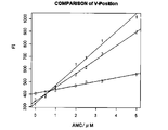
- the light source is arranged in the vertical direction (V-0, V-1, V-2) or in the horizontal direction (H (1), (2), (3)). And examined.
- FIG. 5 1 shows the measured value at the H- (3) position, and 2 shows the measured value at the H- (2) position (fixed in the vertical direction V- (0)).
- the measurement value at the position H- (1) is omitted.
- AMC Fluorescence intensity vs. product concentration
- AMC was dissolved in 0.1 M HEPES buffer, pH 7.2 to prepare 1 to 10 ⁇ M solutions, and 100 ⁇ L each of these was prepared in a microtube (A-1500, manufactured by Assist Corporation; volume, 1.5 mL; length, 450 mm; screw-type lid stopper or less, 350 mm; taper position, 20 mm from below; outer diameter, 10 mm; inner diameter, 8 mm; side wall thickness, 1 mm), and using the fluorescence measuring apparatus of the present invention shown in FIG.
- the light intensity having a peak of 365 nm ⁇ 10 nm was irradiated, the condition for receiving light at 442 nm was set, and the fluorescence intensity was measured.
- the results are shown in FIG.
- the fluorescence intensity and the AMC concentration showed a substantially linear relationship. From these results, it was shown that according to the present invention, the fluorescence of AMC can be detected with high sensitivity and the AMC
- Measurement box 2 Microtube 3 Container support 4 LED 5 Vertical Position Control Unit 6 Horizontal Position Control Unit 7 Interference Filter 8 Light Receiving Element 9 Temperature Control Heating Body PTC DESCRIPTION OF SYMBOLS 10 Temperature sensor 11 Measurement box upper part operation cap 20 Control box 21 Current control part 22 Signal amplifier 23 LCD display 24 Main control part 25 Temperature control part (1) 26 Temperature controller (2) 27 Host system
Landscapes
- Health & Medical Sciences (AREA)
- Life Sciences & Earth Sciences (AREA)
- Pathology (AREA)
- General Health & Medical Sciences (AREA)
- Analytical Chemistry (AREA)
- Chemical & Material Sciences (AREA)
- Biochemistry (AREA)
- Physics & Mathematics (AREA)
- General Physics & Mathematics (AREA)
- Immunology (AREA)
- Nuclear Medicine, Radiotherapy & Molecular Imaging (AREA)
- Molecular Biology (AREA)
- Biomedical Technology (AREA)
- Engineering & Computer Science (AREA)
- Heart & Thoracic Surgery (AREA)
- Medical Informatics (AREA)
- Surgery (AREA)
- Animal Behavior & Ethology (AREA)
- Public Health (AREA)
- Veterinary Medicine (AREA)
- Investigating, Analyzing Materials By Fluorescence Or Luminescence (AREA)
Abstract
Priority Applications (3)
| Application Number | Priority Date | Filing Date | Title |
|---|---|---|---|
| DE112011103252T DE112011103252T5 (de) | 2010-09-28 | 2011-09-28 | Fluoreszenzmessverfahren und Fluoreszenzmessvorrichtung |
| US13/825,572 US8848188B2 (en) | 2010-09-28 | 2011-09-28 | Fluorescence measurement method and fluorescence measurement device |
| KR1020137008913A KR101503274B1 (ko) | 2010-09-28 | 2011-09-28 | 형광 측정방법 및 형광 측정장치 |
Applications Claiming Priority (2)
| Application Number | Priority Date | Filing Date | Title |
|---|---|---|---|
| JP2010217958A JP5669087B2 (ja) | 2010-09-28 | 2010-09-28 | 蛍光測定方法及び蛍光測定装置 |
| JP2010-217958 | 2010-09-28 |
Publications (1)
| Publication Number | Publication Date |
|---|---|
| WO2012042870A1 true WO2012042870A1 (fr) | 2012-04-05 |
Family
ID=45892359
Family Applications (1)
| Application Number | Title | Priority Date | Filing Date |
|---|---|---|---|
| PCT/JP2011/005469 Ceased WO2012042870A1 (fr) | 2010-09-28 | 2011-09-28 | Procédé et dispositif de mesure de la fluorescence |
Country Status (5)
| Country | Link |
|---|---|
| US (1) | US8848188B2 (fr) |
| JP (1) | JP5669087B2 (fr) |
| KR (1) | KR101503274B1 (fr) |
| DE (1) | DE112011103252T5 (fr) |
| WO (1) | WO2012042870A1 (fr) |
Cited By (2)
| Publication number | Priority date | Publication date | Assignee | Title |
|---|---|---|---|---|
| JP2022119505A (ja) * | 2021-02-04 | 2022-08-17 | 学校法人東京歯科大学 | 歯周病の原因菌を判別する試薬、菌種判別方法、口臭リスク判定方法および蛍光測定装置 |
| JP2022119510A (ja) * | 2021-02-04 | 2022-08-17 | 学校法人東京歯科大学 | 判別方法および蛍光測定装置 |
Families Citing this family (13)
| Publication number | Priority date | Publication date | Assignee | Title |
|---|---|---|---|---|
| FR3023375B1 (fr) * | 2014-07-01 | 2018-03-02 | Eric Lopez | Dispositif et procede de mesure mobile spectrometrique de cereales, oleagineux ou produits derives relevant de la filiere agro-alimentaire |
| DE102015118175A1 (de) * | 2015-10-23 | 2017-04-27 | Marc Breit | Vorrichtung zur Emission elektromagnetischer Strahlung, insbesondere UV-Strahlung |
| JP6600527B2 (ja) | 2015-10-15 | 2019-10-30 | 自然免疫制御技術研究組合 | 貪食能評価方法及び蛍光測定方法 |
| JP2017106794A (ja) * | 2015-12-09 | 2017-06-15 | ウシオ電機株式会社 | 光測定装置 |
| JP6686800B2 (ja) * | 2016-08-31 | 2020-04-22 | ウシオ電機株式会社 | 光学測定器 |
| JP2019046861A (ja) * | 2017-08-30 | 2019-03-22 | 株式会社東芝 | 光学センサ |
| CN107817235A (zh) * | 2017-12-11 | 2018-03-20 | 苏州合惠生物科技有限公司 | 一种实时荧光定量扩增检测仪 |
| US11592395B2 (en) * | 2019-03-22 | 2023-02-28 | Kaya17 Inc. | Wide-area-sample based reader design for diagnostic detection of bio-particles |
| CN111487246B (zh) * | 2020-04-20 | 2023-06-20 | 中国农业科学院烟草研究所 | 一种烟草青枯病试纸条批次质量检测装置 |
| CN111504972B (zh) * | 2020-05-21 | 2024-07-23 | 朱建国 | 一种pcr采样检测装置 |
| US11872038B2 (en) | 2020-09-04 | 2024-01-16 | Covidien Lp | Medical device including diffuse reflector for detecting fluid parameters |
| CN112285072A (zh) * | 2020-09-04 | 2021-01-29 | 马鞍山国声生物技术有限公司 | 一种pct层析检测装置 |
| US11872355B2 (en) | 2020-09-04 | 2024-01-16 | Covidien Lp | Medical device for detecting fluid parameters using fluorescent probes |
Citations (8)
| Publication number | Priority date | Publication date | Assignee | Title |
|---|---|---|---|---|
| JPH08500183A (ja) * | 1992-08-13 | 1996-01-09 | メッヒラー、マインラート | 少量および微量物質を分析するための分光装置 |
| JP2004163257A (ja) * | 2002-11-13 | 2004-06-10 | National Institute Of Advanced Industrial & Technology | 光導波路への光導入方法及びそれを用いた光導波路分光測定装置 |
| JP2005140683A (ja) * | 2003-11-07 | 2005-06-02 | Sekisui Chem Co Ltd | 光学的測定装置及びそれを用いた特異的結合物の光学的測定方法 |
| JP2005201859A (ja) * | 2004-01-19 | 2005-07-28 | Taitec Corp | Dna等試料の増幅の蛍光目視判定機能を持つ恒温槽 |
| JP2007113996A (ja) * | 2005-10-19 | 2007-05-10 | Funai Electric Co Ltd | 測定装置 |
| JP2007521485A (ja) * | 2003-06-23 | 2007-08-02 | アプレラ コーポレイション | 生物学的物質のためのサンプルウェルおよびマイクロカード用のキャップ |
| JP2008541139A (ja) * | 2005-05-04 | 2008-11-20 | スリーエム イノベイティブ プロパティズ カンパニー | 蛍光検出で使用されるパルス光源用のシステムおよび方法 |
| JP2010122146A (ja) * | 2008-11-21 | 2010-06-03 | Olympus Corp | 測定系 |
Family Cites Families (14)
| Publication number | Priority date | Publication date | Assignee | Title |
|---|---|---|---|---|
| US4291230A (en) * | 1979-03-07 | 1981-09-22 | Baxter Travenol Laboratories, Inc. | Fluorometric analyzer including shutter means for simultaneously shielding sample and photodetector during sample change |
| JPH0634546A (ja) | 1992-07-17 | 1994-02-08 | Tosoh Corp | 蛍光検出器 |
| JP3855485B2 (ja) * | 1998-09-09 | 2006-12-13 | 東ソー株式会社 | スキャナー型蛍光検出装置 |
| JP4013868B2 (ja) | 2003-04-11 | 2007-11-28 | 株式会社島津製作所 | 蛍光検出装置 |
| JP4367004B2 (ja) | 2003-05-27 | 2009-11-18 | トヨタ自動車株式会社 | 回転電機用ロータ |
| JP2004354347A (ja) | 2003-05-30 | 2004-12-16 | Olympus Corp | 蛍光測定装置 |
| SE0400191D0 (sv) | 2004-01-30 | 2004-01-30 | Tendera Ab | A test kit for detecting periodontal disease |
| WO2007027634A2 (fr) * | 2005-08-31 | 2007-03-08 | Stratagene California | Module optique compact pour excitation et detection de fluorescence |
| US7801394B2 (en) * | 2005-10-03 | 2010-09-21 | Creatv Microtech, Inc. | Sensitive emission light gathering and detection system |
| US7651869B2 (en) * | 2006-03-14 | 2010-01-26 | Research International, Inc. | Optical assay apparatus and methods |
| JP4864743B2 (ja) | 2007-01-30 | 2012-02-01 | 富士フイルム株式会社 | 蛍光測定装置 |
| DE102007020610A1 (de) * | 2007-04-30 | 2008-11-20 | Thomas Dr. Ruckstuhl | Behälter und Verfahren zum Nachweis von Fluoreszenz |
| JP2008289437A (ja) | 2007-05-28 | 2008-12-04 | Sony Corp | レーザーを用いた酵素活性測定方法及び酵素活性測定装置 |
| JP2010190713A (ja) | 2009-02-18 | 2010-09-02 | Imac Co Ltd | 蛍光測定装置 |
-
2010
- 2010-09-28 JP JP2010217958A patent/JP5669087B2/ja active Active
-
2011
- 2011-09-28 WO PCT/JP2011/005469 patent/WO2012042870A1/fr not_active Ceased
- 2011-09-28 KR KR1020137008913A patent/KR101503274B1/ko not_active Expired - Fee Related
- 2011-09-28 DE DE112011103252T patent/DE112011103252T5/de not_active Withdrawn
- 2011-09-28 US US13/825,572 patent/US8848188B2/en active Active
Patent Citations (8)
| Publication number | Priority date | Publication date | Assignee | Title |
|---|---|---|---|---|
| JPH08500183A (ja) * | 1992-08-13 | 1996-01-09 | メッヒラー、マインラート | 少量および微量物質を分析するための分光装置 |
| JP2004163257A (ja) * | 2002-11-13 | 2004-06-10 | National Institute Of Advanced Industrial & Technology | 光導波路への光導入方法及びそれを用いた光導波路分光測定装置 |
| JP2007521485A (ja) * | 2003-06-23 | 2007-08-02 | アプレラ コーポレイション | 生物学的物質のためのサンプルウェルおよびマイクロカード用のキャップ |
| JP2005140683A (ja) * | 2003-11-07 | 2005-06-02 | Sekisui Chem Co Ltd | 光学的測定装置及びそれを用いた特異的結合物の光学的測定方法 |
| JP2005201859A (ja) * | 2004-01-19 | 2005-07-28 | Taitec Corp | Dna等試料の増幅の蛍光目視判定機能を持つ恒温槽 |
| JP2008541139A (ja) * | 2005-05-04 | 2008-11-20 | スリーエム イノベイティブ プロパティズ カンパニー | 蛍光検出で使用されるパルス光源用のシステムおよび方法 |
| JP2007113996A (ja) * | 2005-10-19 | 2007-05-10 | Funai Electric Co Ltd | 測定装置 |
| JP2010122146A (ja) * | 2008-11-21 | 2010-06-03 | Olympus Corp | 測定系 |
Cited By (4)
| Publication number | Priority date | Publication date | Assignee | Title |
|---|---|---|---|---|
| JP2022119505A (ja) * | 2021-02-04 | 2022-08-17 | 学校法人東京歯科大学 | 歯周病の原因菌を判別する試薬、菌種判別方法、口臭リスク判定方法および蛍光測定装置 |
| JP2022119510A (ja) * | 2021-02-04 | 2022-08-17 | 学校法人東京歯科大学 | 判別方法および蛍光測定装置 |
| JP7430313B2 (ja) | 2021-02-04 | 2024-02-13 | 学校法人東京歯科大学 | 歯周病の原因菌を判別する試薬、菌種判別方法、口臭リスク判定方法および蛍光測定装置 |
| JP7479610B2 (ja) | 2021-02-04 | 2024-05-09 | 学校法人東京歯科大学 | 判別方法および蛍光測定装置 |
Also Published As
| Publication number | Publication date |
|---|---|
| US20130260405A1 (en) | 2013-10-03 |
| JP2012073109A (ja) | 2012-04-12 |
| DE112011103252T5 (de) | 2013-06-27 |
| US8848188B2 (en) | 2014-09-30 |
| KR101503274B1 (ko) | 2015-03-17 |
| JP5669087B2 (ja) | 2015-02-12 |
| KR20130052641A (ko) | 2013-05-22 |
Similar Documents
| Publication | Publication Date | Title |
|---|---|---|
| JP5669087B2 (ja) | 蛍光測定方法及び蛍光測定装置 | |
| US8279434B2 (en) | Arrangement and method for analysis of biological samples | |
| JPH0115811B2 (fr) | ||
| US8562801B2 (en) | Electrode with integrated optical sensor | |
| ES2365079T3 (es) | Sistema de detección y cuantificación de material biológico constituido por uno o más sensores ópticos y una o más fuentes de luz, proceso asociado y aplicaciones relacionadas. | |
| JP2005516596A (ja) | 蓋要素 | |
| TW201221937A (en) | Scattering light source multi-wavelength photometer | |
| Wiejata et al. | Fluorescent sensing using biconical tapers | |
| WO2014045833A1 (fr) | Méthode d'évaluation du vieillissement, et dispositif associé | |
| CN114270173A (zh) | 用于多参数分析介质的传感器模块 | |
| Steinwedel et al. | Sensors for disposable bioreactor systems | |
| US10385305B2 (en) | Device for measuring activity of cultured cells, microchamber and method of measuring activity of cultured cells | |
| EP4058550A1 (fr) | Récipients de culture cellulaire et systèmes de surveillance pour la surveillance non invasive d'une culture cellulaire | |
| JP3529014B2 (ja) | 細胞培養容器 | |
| KR200458306Y1 (ko) | 고감도 휴대용 fret 형광측정 장치 | |
| US10107739B2 (en) | System and method for confocal raman-spectroscopic measurements of biological samples | |
| WO2002103339A1 (fr) | Procede d'analyse spectroscopique a conversion photothermique et systeme d'analyse spectroscopique a conversion photothermique permettant d'executer ledit procede | |
| CN101283241A (zh) | 识别和量化悬浮于液体中的生物样品的系统及方法 | |
| US20150125899A1 (en) | Fluorescence-assisted counting apparatus for qualitative and/or quantitative measurement of fluorescently tagged particles | |
| JP3016640B2 (ja) | 光導波路型バイオセンサ | |
| JP2005062023A (ja) | 落射型蛍光測定装置 | |
| JP2005241435A (ja) | 生細胞の計数方法および装置 | |
| US12601685B2 (en) | Rapid diagnostics for analyte/biomarker detection by Raman technology with non-spectrometer Raman measurement system | |
| JP2013046576A (ja) | 微生物等の検査方法及び検査装置 | |
| JP2011214858A (ja) | クロマトグラフ測定方法、並びにそれに用いる不溶性担体および測定装置 |
Legal Events
| Date | Code | Title | Description |
|---|---|---|---|
| 121 | Ep: the epo has been informed by wipo that ep was designated in this application |
Ref document number: 11828436 Country of ref document: EP Kind code of ref document: A1 |
|
| WWE | Wipo information: entry into national phase |
Ref document number: 112011103252 Country of ref document: DE Ref document number: 1120111032528 Country of ref document: DE |
|
| ENP | Entry into the national phase |
Ref document number: 20137008913 Country of ref document: KR Kind code of ref document: A |
|
| WWE | Wipo information: entry into national phase |
Ref document number: 13825572 Country of ref document: US |
|
| 122 | Ep: pct application non-entry in european phase |
Ref document number: 11828436 Country of ref document: EP Kind code of ref document: A1 |