WO2012042880A1 - 生体分子検出装置および生体分子検出方法 - Google Patents
生体分子検出装置および生体分子検出方法 Download PDFInfo
- Publication number
- WO2012042880A1 WO2012042880A1 PCT/JP2011/005487 JP2011005487W WO2012042880A1 WO 2012042880 A1 WO2012042880 A1 WO 2012042880A1 JP 2011005487 W JP2011005487 W JP 2011005487W WO 2012042880 A1 WO2012042880 A1 WO 2012042880A1
- Authority
- WO
- WIPO (PCT)
- Prior art keywords
- light
- orientation control
- fluorescence
- molecule
- orientation
- Prior art date
- Legal status (The legal status is an assumption and is not a legal conclusion. Google has not performed a legal analysis and makes no representation as to the accuracy of the status listed.)
- Ceased
Links
Images









Classifications
-
- G—PHYSICS
- G01—MEASURING; TESTING
- G01N—INVESTIGATING OR ANALYSING MATERIALS BY DETERMINING THEIR CHEMICAL OR PHYSICAL PROPERTIES
- G01N21/00—Investigating or analysing materials by the use of optical means, i.e. using sub-millimetre waves, infrared, visible or ultraviolet light
- G01N21/62—Systems in which the material investigated is excited whereby it emits light or causes a change in wavelength of the incident light
- G01N21/63—Systems in which the material investigated is excited whereby it emits light or causes a change in wavelength of the incident light optically excited
- G01N21/64—Fluorescence; Phosphorescence
- G01N21/6486—Measuring fluorescence of biological material, e.g. DNA, RNA, cells
-
- G—PHYSICS
- G01—MEASURING; TESTING
- G01N—INVESTIGATING OR ANALYSING MATERIALS BY DETERMINING THEIR CHEMICAL OR PHYSICAL PROPERTIES
- G01N21/00—Investigating or analysing materials by the use of optical means, i.e. using sub-millimetre waves, infrared, visible or ultraviolet light
- G01N21/62—Systems in which the material investigated is excited whereby it emits light or causes a change in wavelength of the incident light
- G01N21/63—Systems in which the material investigated is excited whereby it emits light or causes a change in wavelength of the incident light optically excited
- G01N21/64—Fluorescence; Phosphorescence
- G01N21/6445—Measuring fluorescence polarisation
-
- G—PHYSICS
- G01—MEASURING; TESTING
- G01N—INVESTIGATING OR ANALYSING MATERIALS BY DETERMINING THEIR CHEMICAL OR PHYSICAL PROPERTIES
- G01N21/00—Investigating or analysing materials by the use of optical means, i.e. using sub-millimetre waves, infrared, visible or ultraviolet light
- G01N21/62—Systems in which the material investigated is excited whereby it emits light or causes a change in wavelength of the incident light
- G01N21/63—Systems in which the material investigated is excited whereby it emits light or causes a change in wavelength of the incident light optically excited
- G01N21/64—Fluorescence; Phosphorescence
- G01N21/6428—Measuring fluorescence of fluorescent products of reactions or of fluorochrome labelled reactive substances, e.g. measuring quenching effects, using measuring "optrodes"
-
- G—PHYSICS
- G01—MEASURING; TESTING
- G01N—INVESTIGATING OR ANALYSING MATERIALS BY DETERMINING THEIR CHEMICAL OR PHYSICAL PROPERTIES
- G01N33/00—Investigating or analysing materials by specific methods not covered by groups G01N1/00 - G01N31/00
- G01N33/48—Biological material, e.g. blood, urine; Haemocytometers
- G01N33/50—Chemical analysis of biological material, e.g. blood, urine; Testing involving biospecific ligand binding methods; Immunological testing
- G01N33/53—Immunoassay; Biospecific binding assay; Materials therefor
- G01N33/543—Immunoassay; Biospecific binding assay; Materials therefor with an insoluble carrier for immobilising immunochemicals
- G01N33/54366—Apparatus specially adapted for solid-phase testing
- G01N33/54373—Apparatus specially adapted for solid-phase testing involving physiochemical end-point determination, e.g. wave-guides, FETS, gratings
-
- G—PHYSICS
- G01—MEASURING; TESTING
- G01N—INVESTIGATING OR ANALYSING MATERIALS BY DETERMINING THEIR CHEMICAL OR PHYSICAL PROPERTIES
- G01N21/00—Investigating or analysing materials by the use of optical means, i.e. using sub-millimetre waves, infrared, visible or ultraviolet light
- G01N21/62—Systems in which the material investigated is excited whereby it emits light or causes a change in wavelength of the incident light
- G01N21/63—Systems in which the material investigated is excited whereby it emits light or causes a change in wavelength of the incident light optically excited
- G01N21/64—Fluorescence; Phosphorescence
- G01N21/6428—Measuring fluorescence of fluorescent products of reactions or of fluorochrome labelled reactive substances, e.g. measuring quenching effects, using measuring "optrodes"
- G01N2021/6439—Measuring fluorescence of fluorescent products of reactions or of fluorochrome labelled reactive substances, e.g. measuring quenching effects, using measuring "optrodes" with indicators, stains, dyes, tags, labels, marks
Definitions
- the present invention relates to a technique for detecting a detection target substance in a solution, and more particularly to a biomolecule detection apparatus and a biomolecule detection method capable of detecting biomolecules, viruses, nucleic acids, proteins, bacteria, and the like in a specimen. .
- the biomolecule detection method is a method that selectively detects only a substance to be detected from a bodily fluid having a plurality of components such as blood, urine, and sweat by high selectivity using a specific reaction such as an antigen-antibody reaction. is there.
- a biomolecule detection method is widely used particularly for detection, inspection, quantification and analysis of biomolecules such as viruses, nucleic acids, proteins and bacteria.
- Radioimmunoassay has been put to practical use as a biomolecule detection method.
- an antigen or antibody labeled with an isotope is used to detect the presence or absence of an antibody or antigen that specifically binds to the antigen or antibody.
- the radioimmunoassay quantifies a detection target substance such as an antibody or an antigen by measuring the radiation dose of an isotope, and can perform highly sensitive measurement.
- Fluorescence immunoassay is a biomolecule detection method that does not use radioactive substances.
- the antibody is immobilized on the reaction layer in advance (the reaction layer on which the antibody is immobilized is referred to as a solid phase), and the solution to be measured and the antibody labeled with the fluorescent molecule are passed through the reaction layer.
- An apparatus for measuring the concentration of an antigen specifically bound to an antibody by measuring the nearby fluorescence is known (see, for example, Patent Document 1).
- the fluorescence immunoassay using a solid phase has a problem that it takes a high cost to prepare the solid phase.
- a method for detecting a biomolecule in a liquid without using a solid phase that is, using only the liquid phase
- the fluorescence polarization method is a method for detecting a change in the value of the degree of fluorescence polarization based on a change in Brownian motion, which occurs when another molecule binds to a fluorescently labeled molecule and the size of the molecule changes.
- a biomolecule detection method using a fluorescence polarization method is known as a simple and quick detection method for a substance to be detected in a specimen (see, for example, Patent Document 2).
- the conventional fluorescence polarization method has a problem in that there is a limit in measurement sensitivity because it uses a change in Brownian motion, which is a random motion.
- the fluorescence lifetime needs to be long enough to be affected by the change in Brownian motion.
- the measurement results obtained by the method of Patent Document 2 may vary.
- the present invention has been made in view of the above circumstances, and an object thereof is to provide a biomolecule detection apparatus and a biomolecule detection method capable of highly sensitive measurement.
- a biomolecule detection apparatus comprises: Fluorescence generated from a first complex having a substance that specifically binds to the detection target substance and a fluorescent molecule, and fluorescence generated from a second complex in which the first complex and the detection target substance are bound
- Fluorescence generated from a first complex having a substance that specifically binds to the detection target substance and a fluorescent molecule, and fluorescence generated from a second complex in which the first complex and the detection target substance are bound Is a biomolecule detection device that detects or quantifies a detection target substance present in a solution, A light source that emits excitation light having a linearly polarized component in a specific direction to excite fluorescent molecules; A light receiving portion for detecting fluorescence generated from the fluorescent molecules; An orientation control means for periodically switching and orienting the second complex in the solution; Synchronous component extraction means for extracting a component synchronized with the period in which the second complex is oriented among the fluorescence detected by the light receiving unit; And a calculation unit that detects or quantifies the detection target
- the orientation control means includes a first direction in which the transition moment of the fluorescent molecule included in the second complex is parallel to the vibration direction of the linearly polarized component of the excitation light, and The transition moment is preferably switched and oriented in the second direction perpendicular to the vibration direction.
- the cycle of switching and orienting the second complex includes the molecular weight or volume of the detection target substance, the molecular weight of the substance that specifically binds to the detection target substance, and the fluorescent molecule or It is preferably determined based on the volume and the strength of orientation control by the orientation control means.
- the orientation control means preferably includes an orientation control light source that orients the second complex by irradiating light having a wavelength different from that of the excitation light.
- the orientation control light source irradiates the solution with the light having a wavelength different from that of the excitation light from a plurality of positions.
- the orientation control means includes an orientation control light source
- the orientation control light source irradiates the light having a wavelength different from that of the excitation light in the direction of exiting from the plane of the solution holding portion through the solution, and the excitation light is emitted at the interface between the solution and the plane. It is preferable to focus on the light having different wavelengths.
- the light receiving unit includes a spectroscopic unit that splits light.
- the spectroscopic means is a plurality of filters having different characteristics, and the light receiving unit switches the plurality of filters in accordance with the wavelength of fluorescence.
- the biomolecule detection method includes: Fluorescence generated from a first complex having a substance that specifically binds to the detection target substance and a fluorescent molecule, and fluorescence generated from a second complex in which the first complex and the detection target substance are bound Is a biomolecule detection method for detecting or quantifying a detection target substance present in a solution, Irradiating excitation light having a linearly polarized light component in a specific direction and exciting fluorescent molecules; Periodically switching and orienting the second complex in solution; Detecting fluorescence generated from fluorescent molecules; Extracting a component synchronized with the period in which the second complex is orientated from the detected fluorescence; Detecting or quantifying the detection target substance based on the extracted component.
- biomolecule detection can be performed.
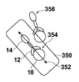
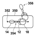
- FIG. 3 is a schematic diagram for explaining an outline of an antigen-antibody reaction of the biomolecule detection apparatus according to the first embodiment.
- FIG. 3 is a schematic diagram for explaining an outline of an antigen-antibody reaction of the biomolecule detection apparatus according to the first embodiment. It is the model showing the case where the vibration direction of excitation light and the transition moment of a fluorescent molecule are mutually parallel. It is a schematic diagram showing the case where the vibration direction of excitation light and the transition moment of fluorescent molecules are perpendicular to each other.
- FIG. 5 is a schematic diagram showing free molecules (fluorescent molecules and antibodies to which no antigen is bound).
- FIG. 3 is a schematic diagram showing binding molecules (fluorescent molecules and antibodies bound by an antigen).
- FIG. 1 is an external perspective view of a biomolecule detection apparatus according to Embodiment 1.
- FIG. 2 is an external perspective view of the biomolecule detection device according to Embodiment 1 with an opening / closing part opened.
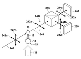
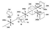
- FIG. It is a block diagram which shows the main structures of a biomolecule detection apparatus. It is the schematic diagram which looked at switching of the irradiation direction of the orientation control light irradiated from the light source part for orientation control from the upper surface. It is the schematic diagram showing the irradiation direction with orientation control light, and the orientation direction of a binding molecule. It is the schematic diagram showing the irradiation direction of the orientation control light orthogonal to the irradiation direction in FIG. 7A, and the orientation direction of a binding molecule.
- FIG. 4 is a schematic diagram illustrating a detailed configuration of a light receiving unit in the biomolecule detection apparatus according to Embodiment 1.
- FIG. It is the figure which represented typically the flow from sample preparation to disposal.
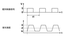
- 4 is a graph showing an orientation control signal and PD output in the biomolecule detection apparatus according to Embodiment 1.
- 3 is a graph showing a lock-in amplifier output in the biomolecule detection apparatus according to the first embodiment.
- 6 is a schematic diagram for explaining an outline of an antigen-antibody reaction of the biomolecule detection apparatus according to Embodiment 2.
- FIG. 6 is a schematic diagram for explaining an outline of an antigen-antibody reaction of the biomolecule detection apparatus according to Embodiment 2.
- FIG. 6 is a block diagram illustrating a main configuration of a biomolecule detection apparatus according to Embodiment 2.
- 6 is a schematic diagram illustrating a detailed configuration of a light receiving unit in a biomolecule detection apparatus according to Embodiment 2.
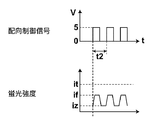
- FIG. 10 is a graph showing PD output for one detection target substance in the second embodiment.
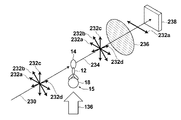
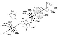
- 6 is a graph showing a PD output for the other detection target substance in the second embodiment. It is a conceptual diagram showing the relationship between the direction of the transition moment of a fluorescent molecule and the vibration direction of randomly polarized excitation light when the orientation control light is irradiated from one side.
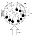
- FIGS. 1A and 1B are schematic diagrams showing an outline of an antigen-antibody reaction in the biomolecule detection apparatus according to Embodiment 1 of the present invention.
- the antigen-antibody reaction in the liquid will be described with reference to FIGS. 1A and 1B.
- one type of antibody is used and one type of antigen is detected in a homogeneous solution.
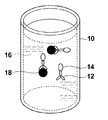
- the dried antibody 12 is placed in the cylindrical reagent cup 10.
- the antibody 12 is labeled with a fluorescent molecule 14.
- the specimen is plasma 16 separated from whole blood.
- the plasma 16 is dispensed into the reagent cup 10 and stirred, if an antigen 18 that specifically binds to the antibody 12 is present in the plasma 16, an antigen-antibody reaction occurs between the antibody 12 and the antigen 18. As shown in 1B, antibody 12 and antigen 18 are specifically bound and present in the plasma solution.
- plasma 16 separated from whole blood is used as a specimen, and PSA (Prostate Specific Antigen) is detected as an antigen 18 that is a detection target substance, and a substance that specifically binds to the detection target substance.
- PSA Prostate Specific Antigen
- a case where an anti-PSA antibody is used as an antibody 12 will be described.
- the fluorescent molecule 14 Alexa Fluor 568 (trade name of Molecular Probes) was used. Alexa Fluor 568 has a peak at a wavelength of about 610 nm and emits fluorescence having a wavelength of about 550 nm to 700 nm.
- the antibody 12 Since the antibody 12 is contained in a sufficiently large amount with respect to the antigen 18, a part of the antibody 12 remains in the plasma 16 without undergoing an antigen-antibody reaction.
- the complex of the antibody 12 and the antigen 18 and the fluorescent molecule 14 bound by the antigen-antibody reaction is called a binding molecule
- the complex of the antibody 12 and the fluorescent molecule 14 floating in the liquid without the antigen-antibody reaction is called a free molecule.
- Binding molecules and free molecules are mixed in plasma 16.
- components other than the antigen 18 exist in the plasma 16
- components other than the antigen 18 are omitted in FIGS. 1A and 1B for the sake of simplicity.
- the biomolecule detection apparatus irradiates excitation light to a solution in which free molecules and binding molecules are mixed due to the liquid phase, and receives fluorescence generated from the fluorescent molecules 14. Then, the antigen 18 is detected and quantified. Therefore, it is desirable to detect only the fluorescence generated from the binding molecule containing the antigen 18.
- fluorescence is also generated from the fluorescent molecules 14 associated with the free molecules. This fluorescence becomes an unnecessary component in relation to the fluorescence generated from the fluorescent molecule 14 accompanying the binding molecule.
- the biomolecule detection apparatus detects fluorescence while switching the orientation of the binding molecule with light, and binds from the total fluorescence data based on the change in fluorescence intensity associated with the orientation change. The contribution of fluorescence generated from the fluorescent molecule 14 accompanying the molecule is calculated.
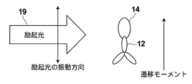
- FIG. 2A is a schematic diagram illustrating a case where the vibration direction of the excitation light 19 and the direction of the transition moment of the fluorescent molecule 14 are parallel to each other
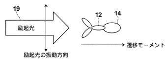
- FIG. 2B illustrates the vibration direction of the excitation light 19 and the direction of the transition moment of the fluorescent molecule 14. It is a schematic diagram showing the case where is perpendicular.
- the longitudinal direction of the fluorescent molecule 14 (the long axis direction of the fluorescent molecule 14 indicated by an ellipse) and the direction of the transition moment are parallel to each other. That is, FIGS.
- FIGS. 2A and 2B are diagrams depicting a case where the direction of the fluorescent molecule 14 (the long axis direction of the fluorescent molecule 14 indicated by an ellipse) and the direction of the transition moment coincide.
- the “vibration direction” of light means the vibration direction of an electric field, and has the same meaning as the polarization direction when light is polarized.
- Fluorescent molecules 14 transition to an excited state when absorbing light energy, and emit fluorescence in the process of returning to the ground state.
- the fluorescent molecule 14 when the fluorescent molecule 14 is excited with linearly polarized excitation light, the fluorescent molecule 14 emits fluorescence polarized in the same direction as the vibration direction of the excitation light.
- the degree of polarization of the fluorescence generated from the fluorescent molecule 14 depends on the rotational speed of the fluorescent molecule 14. In other words, if the fluorescent molecule 14 does not rotate, the fluorescent molecule 14 emits fluorescence polarized in the same direction as the vibration direction of the excitation light. The faster the fluorescent molecule 14 rotates, the more the fluorescent molecule 14 is generated. The degree of polarization of fluorescent light is small.
- the fluorescent molecule 14 When the fluorescent molecule 14 is excited, a vector in the fluorescent molecule 14 called a transition moment determined by the molecular structure of the fluorescent molecule 14 interacts with the excitation light 19.
- the transition moment has a specific direction in the fluorescent molecule 14, and the relationship between the direction of the transition moment and the vibration direction of the excitation light 19 determines the excitation efficiency of the fluorescent molecule 14.
- the fluorescent molecule 14 selectively absorbs light that vibrates in a direction parallel to the direction of the transition moment. Therefore, as shown in FIGS. 2A and 2B, when the excitation light 19 travels from left to right while oscillating up and down on the paper surface and hits the fluorescent molecule 14, the vibration direction of the linearly polarized excitation light 19 is the transition of the fluorescent molecule 14.
- the excitation efficiency is highest when parallel to the direction of the moment (FIG. 2A), and the excitation efficiency decreases as the angle between the vibration direction of the linearly polarized excitation light 19 and the direction of the transition moment of the fluorescent molecule 14 increases.
- the vibration direction of the linearly polarized excitation light 19 is orthogonal to the direction of the transition moment of the fluorescent molecule 14 (FIG. 2B)
- the excitation efficiency becomes zero. Since the direction of the transition moment varies depending on the direction of the fluorescent molecule 14, the direction of the fluorescent molecule 14 in the solution affects the excitation efficiency of the fluorescent molecule 14.
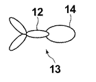
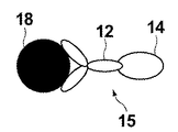
- FIG. 3A is a schematic diagram showing the antibody 12 and the fluorescent molecule 14 constituting the free molecule 13.
- FIG. 3B is a schematic diagram showing the antibody 12, the antigen 18, and the fluorescent molecule 14 constituting the binding molecule.
- the free molecules 13 and the binding molecules 15 move irregularly (Brownian motion) in the solution, and move and rotate in the solution. It is known that the Brownian motion of a molecule in a solution is affected by the absolute temperature, the volume of the molecule, the molecular weight (mass) of the molecule, the viscosity of the solvent, and the like.
- the binding molecule 15 has a volume larger than that of the free molecule 13 by the amount of the antigen 18, and does not easily perform Brownian motion in the solution.
- a method for detecting the binding molecule 15 from a change in Brownian motion by utilizing the ease of Brownian motion of the free molecule 13 and the binding molecule 15 in a solution is known. Since motion is used, detection sensitivity is limited.
- the biomolecule detection apparatus periodically aligns the binding molecules 15 in the solution using a laser, and detects only the signals that match the alignment period, thereby detecting the binding molecules 15. The contribution of the fluorescence generated from is calculated.
- the free molecules 13 and the binding molecules 15 in the solution When the free molecules 13 and the binding molecules 15 in the solution are irradiated with laser, the free molecules 13 and the binding molecules 15 in the solution receive an external force.
- the external force received by the binding molecule 15 by the laser is Fb
- the external force received by the free molecule 13 is Ff
- the free molecule 13 and the binding molecule 15 have different volumes and molecular weights depending on the presence or absence of the antigen 18, and therefore when the laser is irradiated.
- the magnitudes of the external forces received by Fb are different from each other and Fb> Ff.
- the free molecules 13 and the binding molecules 15 are different in the ease of Brownian motion of these molecules in the solution due to differences in volume or molecular weight. Since the free molecules 13 are smaller in volume and molecular weight than the binding molecules 15, they are more likely to perform Brownian motion. If the force required to orient the binding molecule 15 is Bb, and the force necessary to orient the free molecule 13 is Bf, then Bb> Bf. If Fb> Bb, the binding molecules 15 are oriented, and if Ff ⁇ Bf, the free molecules 13 are not oriented.
- the biomolecule detection apparatus calculates the contribution of fluorescence generated from the binding molecule 15 by periodically aligning only the binding molecule 15 and detecting only the signal that matches the alignment period. I do.
- the factors such as the absolute temperature of the solution, the volume of the molecule, the molecular weight, the viscosity of the solvent, and the laser intensity are determined so that Fb> Bb and Ff ⁇ Bf.
- the biomolecule detection apparatus mainly uses the absolute solution.
- the biomolecule detection apparatus has a function of adjusting the temperature of the solution and a function of adjusting the intensity of the laser.
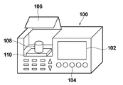
- FIG. 4A is an external perspective view of the biomolecule detection apparatus 100.
- a display unit 102 On the side surface of the biomolecule detection apparatus 100, there are a display unit 102, a user input unit 104, and an opening / closing unit 106.
- the display unit 102 displays measurement results and the like.
- the user input unit 104 is a part where the user sets a mode and inputs sample information.
- the opening / closing unit 106 is configured to be able to open and close the upper lid. The upper lid is opened when the specimen is set, and the upper lid is closed during measurement. With this configuration, external light is prevented from affecting the measurement.
- FIG. 4B is an external perspective view of the biomolecule detection apparatus 100 when the opening / closing part 106 is opened.
- the opening / closing part 106 When the opening / closing part 106 is opened, there are a reagent cup 108 and a holding table 110 inside.
- the reagent cup 108 is held on the holding table 110 and is detachable from the holding table 110.
- the reagent cup 108 is a cylindrical container for storing a solution.
- the user dispenses the sample into the reagent cup 108 and closes the upper lid to perform measurement.
- the biomolecule detection apparatus 100 has a reagent tank and a dispensing unit. When measurement is started, the dispensing unit sucks up the reagent from the reagent tank and dispenses it into the reagent cup 108.
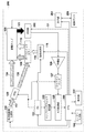
- FIG. 5 is a functional block diagram for explaining the main configuration of the biomolecule detection apparatus 100.
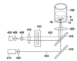
- the biomolecule detection apparatus 100 includes a display unit 102, a user input unit 104, a reagent cup 108, a reagent tank 112, a dispensing unit 114, an orientation control light source unit 116, an excitation light source unit 118, an AOD (Acousto Optical Defector) 120, an FG. (Function Generator) 122, light receiving unit 124, amplification unit 126, lock-in amplifier 127, A / D conversion unit 128, sampling clock generation unit 130, CPU 132, and dichroic mirror 138.
- a display unit 102 includes a display unit 102, a user input unit 104, a reagent cup 108, a reagent tank 112, a dispensing unit 114, an orientation control light source unit 116, an excitation light source unit 118, an AOD (Acousto Optical Defector) 120, an FG
- the reagent cup 108 is a container for reacting a reagent stored in the reagent tank 112 with a sample collected from a patient or the like.
- the reagent cup 108 is detachable from the biomolecule detection apparatus 100.
- the volume of the reagent cup 108 is about 120 ⁇ L, for example.
- the reagent tank 112 is a tank that stores a plurality of types of reagents.
- the free molecules 13 are stored as reagents in the reagent tank 112.
- the dispensing unit 114 is configured by a detachable pipette or a suction device. In accordance with an instruction from the CPU 132, the dispensing unit 114 sucks up the reagent used for measurement from the reagent tank 112 with a pipette and dispenses it into the reagent cup 108.
- the alignment control light source 116 irradiates the alignment control light 117 toward the AOD 120 and applies an external force to the binding molecules existing in the solution in the reagent cup 108 to align the binding molecules. That is, in this specification, the orientation control light source unit 116 corresponds to the orientation control means in the present invention.
- the orientation control light 117 for example, a laser having a wavelength of 980 nm and an output of 700 mW is used.
- the orientation control light 117 is a laser having a wavelength that the fluorescent molecules 14 do not absorb, and has an intensity that does not affect the dye of the fluorescent molecules 14 such as breakage.
- the orientation control light 117 has a width that illuminates the entire solution of the reagent cup 108.
- the excitation light source unit 118 excites the fluorescent molecules 14 by irradiating the reagent cup 108 with the excitation light 119 linearly polarized by the polarizer provided therein through the dichroic mirror 138.
- the excitation light for example, light having a wavelength of 532 nm and an output of 10 mW is used.
- the dichroic mirror 138 is a mirror that reflects light of a specific wavelength and transmits light of other wavelengths.
- the dichroic mirror 138 reflects the orientation control light 117 and transmits the excitation light 119.
- the AOD 120 switches the traveling direction of incident light by changing the internal refractive index based on the input voltage using the acousto-optic effect.
- the AOD 120 changes the internal refractive index based on a voltage input by a voltage signal output from an FG (Function Generator) 122 (hereinafter, an output signal to the AOD 120 is referred to as an alignment control signal), thereby controlling the alignment control light 117.
- an output signal to the AOD 120 is referred to as an alignment control signal
- Switch the direction of travel In other words, the traveling direction of the alignment control light 117 is determined by the alignment control signal generated by the FG 122.
- the AOD 120 alternates the direction in which the orientation control light 117 travels in the direction in which the reagent cup 108 is irradiated (indicated by an arrow 134 in the figure) and in the direction in which the dichroic mirror 138 is irradiated (indicated by an arrow 136 in the figure). Switch.
- the FG 122 is a device that can generate voltage signals having various frequencies and waveforms, and outputs a voltage signal to the AOD 120, the lock-in amplifier 127, and the sampling clock generator 130 in response to a command output from the CPU 132. .
- the CPU 132 controls the timing at which the AOD 120 switches the traveling direction of the orientation control light 117 by designating the orientation control signal output to the FG 122.
- the light receiving unit 124 is configured by a filter, a photodiode, or the like.
- the light receiving unit 124 is provided below the reagent cup 108, receives fluorescence 123 generated from the fluorescent molecules 14 in the reagent cup 108 at the lower part of the reagent cup 108, and receives the received light signal as an analog electrical signal (analog fluorescence data). ) And output to the amplifying unit 126.
- the amplifying unit 126 amplifies the analog fluorescence data output from the light receiving unit 124 and outputs the amplified data to the lock-in amplifier 127.
- the lock-in amplifier 127 converts the analog fluorescence data to a direct current.
- the lock-in amplifier 127 receives a square wave as a reference signal from the FG 122.
- the lock-in amplifier 127 detects a frequency component equal to the frequency of the reference signal from the analog fluorescence data output from the amplification unit 126.
- the lock-in amplifier 127 converts only a frequency component equal to the frequency of the reference signal into a DC signal by synchronous detection, and passes only the DC signal through a low-pass filter provided therein.
- the lock-in amplifier 127 outputs a DC signal to the A / D conversion unit 128.
- the lock-in amplifier 127 corresponds to the synchronous component extraction means in the present invention.
- the sampling clock generation unit 130 outputs to the A / D conversion unit 128 a sampling clock that specifies the timing at which the A / D conversion unit 128 samples the analog fluorescence data based on the voltage signal output from the FG 122.
- the A / D converter 128 samples the analog fluorescence data output from the lock-in amplifier 127 based on the sampling clock output from the sampling clock generator 130, and converts the sampled analog fluorescence data into digital data. To the CPU 132.
- the CPU 132 calculates the digital data output from the A / D conversion unit 128 and outputs the result to the display unit 102. Further, the CPU 132 receives an input from the user input unit 104 and issues an instruction command for operations of the orientation control light source unit 116, the excitation light source unit 118, the dispensing unit 114, and the FG 122. Specifically, the CPU 132 issues an ON / OFF command to the orientation control light source unit 116 and the excitation light source unit 118, and instructs the dispensing unit 114 to specify a reagent to be used and a dispensing operation. A start command is issued, and an instruction command and an output command for the waveform of the voltage signal to be output are issued to the FG 122.
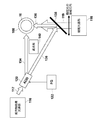
- FIG. 6 is a schematic view of the inside of the biomolecule detection apparatus 100 as viewed from the upper surface side in order to explain switching of the irradiation direction of the laser irradiated from the light source unit 116 for orientation control.
- the alignment control light 117 irradiated from the alignment control light source unit 116 is irradiated to the reagent cup 108 through the AOD 120.
- the orientation control light 117 has a width that illuminates the entire solution of the reagent cup 108.
- the AOD 120 alternately switches the irradiation direction of the alignment control light 117 irradiated from the alignment control light source unit 116 in two directions. Specifically, the AOD 120 advances the orientation control light 117 in the direction of the arrow 134 when a 5V orientation control signal is output from the FG 122, and when the FG 122 outputs a 0V orientation control signal. Then, the orientation control light 117 is advanced in the direction of the arrow 136.
- the orientation control light 117 traveling in the direction of the arrow 134 is incident on the side surface of the reagent cup 108 as it is.
- the orientation control light 117 traveling in the direction of the arrow 136 is reflected by the dichroic mirror 138, travels in a direction perpendicular to the direction of the arrow 134, and enters the side surface of the reagent cup 108. If the reagent cup 108 viewed from the top is compared to a clock face, the orientation control light 117 traveling in the direction of the arrow 134 enters from the 9 o'clock position, proceeds in the 3 o'clock direction, and proceeds in the direction of the arrow 136.
- the alignment control light 117 enters from the 6 o'clock position and travels in the 12 o'clock direction. That is, the direction in which the orientation control light 117 traveling in the direction of the arrow 134 enters the reagent cup 108 and the direction in which the orientation control light 117 advanced in the direction of the arrow 136 enters the reagent cup 108 are orthogonal to each other.
- the dichroic mirror 138 reflects only light having the wavelength used for the orientation control light 117 and transmits light having other wavelengths. Excitation light 119 emitted from the excitation light source unit 118 passes through the dichroic mirror 138, travels in the same direction as the orientation control light 117 reflected by the dichroic mirror 138, and enters the side surface of the reagent cup 108.
- the biomolecule detection apparatus 100 controls the AOD 120 by inputting an orientation control signal from the FG 122, whereby the directions in which the orientation control light 117 enters the reagent cup 108 are different from each other by 90 degrees. It can be switched alternately in one direction.
- the biomolecule detection apparatus 100 is configured so that the orientation control light 117 traveling in directions other than the directions indicated by the arrows 134 and 136 is not irradiated to the reagent cup 108. ing.
- the orientation control light 117 is incident on the side surface of the cylindrical reagent cup 108 when traveling in either direction of the arrows 134 and 136. Since the reagent cup 108 is a cylinder, even if the traveling direction of the orientation control light 117 is switched, the shape of the side surface of the reagent cup 108 on which the orientation control light 117 is incident is the same.
- FIG. 7A is a schematic diagram showing one irradiation direction of the orientation control light 117 and the orientation direction of the binding molecule
- FIG. 7B shows the other irradiation direction of the orientation control light 117 and the orientation direction of the binding molecule.
- FIG. 7A and 7B are views of the reagent cup 108 as viewed from above.
- the “orientation direction” with respect to free molecules and binding molecules means the direction in which antibodies and fluorescent molecules are arranged in a state where the switching of the orientation is completed.
- the binding molecules 15 in the reagent cup 108 irradiated with the orientation control light 117 are subjected to an external force by the orientation control light 117 and are oriented in a specific direction.
- the external force due to the alignment control light 117 is generated as a reaction in which the alignment control light 117 strikes the binding molecule 15 and scatters.
- the direction in which the force is applied is determined by the relationship with the direction (the direction in which the fluorescent molecule 14, the antibody 12, and the antigen 18 are arranged).
- the binding molecules 15 irradiated with the alignment control light 117 traveling from the left to the right of the paper surface receive a force in a direction (rotation direction) rotated by the alignment control light 117, and the alignment control light 117.
- the external force of the orientation control light 117 is stabilized in the direction in which the rotational force in various directions exerted on the binding molecule 15 is balanced.
- the binding molecule 15 receives an external force of clockwise rotation or counterclockwise rotation when the traveling direction of the alignment control light 117 and the longitudinal direction of the binding molecule 15 do not face the same direction.
- the binding molecules 15 in the reagent cup 108 are all oriented in the same direction (a direction in which the traveling direction of the orientation control light 117 and the longitudinal direction of the binding molecule 15 are parallel) when irradiated with the orientation control light 117. That is, the transition moments of the fluorescent molecules 14 associated with all the binding molecules 15 are aligned in the same direction.
- the free molecules 13 in the reagent cup 108 are not oriented because the force for performing the Brownian motion is stronger than the external force received by the orientation control light 117, and the Brownian motion is performed in the solution.
- the binding molecules 15 that are oriented toward the right side of the paper receive a force in the direction of rotating counterclockwise.
- the binding molecule 15 that has received the orientation control light 117 traveling from the bottom to the top of the paper is stabilized in a direction perpendicular to the direction oriented by the orientation control light 117 traveling from the left to the right of the paper.
- the transition moments of the fluorescent molecules 14 attached to all the binding molecules 15 are aligned so as to be directed in the same direction.
- the free molecules 13 in the reagent cup 108 are not oriented because the force for performing the Brownian motion is stronger than the external force received by the orientation control light 117, and the Brownian motion is performed in the solution.
- the orientation direction of the binding molecules 15 in the solution can be switched by changing the irradiation direction of the orientation control light 117.
- the direction of the transition moment of the fluorescent molecule 14 accompanying the binding molecule 15 oriented by the orientation control light 117 proceeding in the direction of the arrow 134 is parallel to the direction in which the linearly polarized excitation light 119 vibrates. And the excitation efficiency of the fluorescent molecules 14 is maximized.
- the direction of the transition moment of the fluorescent molecule 14 associated with the binding molecule oriented by the orientation control light 117 proceeding in the direction of the arrow 136 is perpendicular to the direction in which the linearly polarized excitation light 119 vibrates. The excitation efficiency of becomes zero.
- switching of the irradiation direction of the orientation control light 117 by the AOD 120 switches the excitation efficiency of the fluorescent molecule 14 accompanying the binding molecule 15 with respect to the linearly polarized excitation light 119 between maximum and minimum (when excitation is not possible). It will be.
- the orientation control signal input to the AOD 120 is 5V
- the excitation efficiency of the fluorescent molecule 14 associated with the binding molecule 15 is maximized
- the orientation control signal input to the AOD 120 is 0V
- the excitation efficiency is associated with the binding molecule 15.
- the excitation efficiency of the fluorescent molecule 14 is minimized.
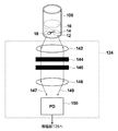
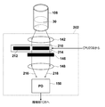
- FIG. 8 is a schematic diagram illustrating a detailed configuration of the light receiving unit 124.
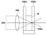
- the light receiving unit 124 includes a lens 142, a filter 144, a polarizer 146, a lens 148, and a PD (photodiode) 150.
- the light receiving unit 124 receives fluorescence from the bottom side of the reagent cup 108.
- Fluorescence 147 generated from the fluorescent molecules 14 in the reagent cup 108 and incident on the left side portion of the light receiving unit 124 and the right side portion of the light receiving unit 124 is condensed and collimated by the lens 142.
- the light enters the PD 150 through the filter 144, the polarizer 146, and the lens 148.
- fluorescence also exists between the fluorescence 147 and the fluorescence 149, and the behavior thereof can be predicted by those skilled in the art, and thus the description thereof is omitted.
- the filter 144 is a band-pass filter that cuts light other than fluorescence generated from the fluorescent molecules 14 and prevents light other than fluorescence, such as excitation light, from entering the PD 150.
- the polarizer 146 transmits only the light polarized in the same direction as the vibration direction of the linearly polarized excitation light 119.
- the excitation light scattered in the reagent cup 108 and the fluorescence emitted from the fluorescent molecules 14 while switching the orientation directions of the free molecules and the binding molecules are different in vibration direction from the original excitation light. Therefore, the light cannot pass through the polarizer 146.
- the PD 150 is configured by an APD (Avalanche Photodiode), receives the fluorescence condensed by the lens 148, generates a charge corresponding to the intensity of the fluorescence, and outputs it to the amplification unit 126.
- APD Anagonal Photodiode
- the light receiving unit 124 converts the fluorescence generated from the fluorescent molecules 14 whose orientation has been switched into charges.
- the light receiving unit 124 since the light receiving unit 124 receives fluorescence on the bottom surface side of the reagent cup 108, the light receiving unit 124 is not easily affected by the orientation control light 117 and the excitation light 119.
- “the switching of the orientation has been completed” means that the molecule has become stable with respect to the external force due to the orientation control light after switching the irradiation direction of the orientation control light.
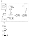
- FIG. 9 is a diagram schematically showing the flow from sample preparation to disposal.
- whole blood 156 collected from a patient is centrifuged at 50 ⁇ L to separate plasma 16.
- the separated plasma 16 is set in the specimen setting unit 152 of the biomolecule detection apparatus 100. The work so far is done by the user.
- the biomolecule detection apparatus 100 dispenses the plasma set in the sample setting unit 152 into an unused reagent cup 108 stocked in the reagent cup stock unit 160. Subsequently, the biomolecule detection apparatus 100 sucks up the anti-PSA antibody in the reagent tank 112 with the pipette 158 and dispenses it into the reagent cup 108.
- the biomolecule detection apparatus 100 in which the plasma and the anti-PSA antibody are placed in the reagent cup 108 causes the antigen-antibody reaction by vibrating the reagent cup 108 with a built-in vortex mixer while controlling the temperature at 37 ° C. Thereafter, the biomolecule detection apparatus 100 performs irradiation with excitation light and fluorescence detection, and discards the reagent cup 108 in the built-in trash box 154 after the fluorescence detection is completed.
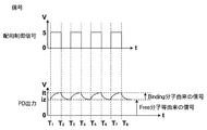
- FIG. 10B An example of an orientation control signal output by the FG 122 during measurement, an example of a PD output output by the PD 150 during measurement, and an example of a lock-in amplifier output output by the lock-in amplifier 127 during measurement are shown in FIG. 10B. Shown in Here, for ease of explanation, graphs are schematically shown for the PD output and the lock-in amplifier output.
- the orientation control signal output from the FG 122 is 0 V before measurement.
- the orientation control signal is a square wave having a period of 2T that outputs a signal of 5 V from 0 to T (seconds) and outputs a 0 V signal from T to 2 T (seconds).
- the orientation control signal is 0 V, the orientation control light 136 is irradiated to the reagent cup 108, and all the binding molecules are oriented in the same direction.
- the biomolecule detection apparatus 100 sets the orientation control signal to 5 V at time T1 and irradiates the reagent cup 108 with excitation light. Thereafter, when the orientation control signal becomes 5V, the AOD 120 switches the traveling direction of the orientation control light 117, and the traveling direction of the orientation control light 117 is switched from the direction of the arrow 136 to the direction of the arrow 134. As the direction of travel of the orientation control light 117 is switched, the irradiation direction of the orientation control light 117 on the reagent cup 108 is also switched by 90 degrees.
- the orientation direction of the binding molecule 15 is switched, and fluorescence 123 is generated when the vibration direction of the excitation light 119 and the direction of the transition moment of the fluorescent molecule 14 are not perpendicular to each other. . Most of the fluorescence generated from the fluorescent molecules 14 accompanying the binding molecules 15 in the course of switching the orientation is blocked by the polarizer 146 because it is not polarized.
- the direction of transition moment is parallel to the vibration direction of the excitation light 119, and the excitation efficiency is maximized. Since the fluorescence generated from the fluorescent molecules accompanying the binding molecules 15 whose orientation has been switched is polarized in the same direction as the excitation light, it reaches the PD 150 without being blocked by the polarizer 146.
- the PD output outputs the value iz.
- the PD output iz is a value including fluorescence generated from the fluorescent molecules 14 associated with some free molecules 13 in the solution and a noise component derived from the device or the like. Since the fluorescent molecules 14 associated with the binding molecules 15 are not excited when the orientation control signal is 0 V, they do not contribute to the PD output.
- the PD output When the orientation control signal changes from 0V to 5V and the fluorescence 123 generated by the fluorescent molecules 14 accompanying the binding molecules 15 whose orientation has been changed reaches the PD, the PD output also increases from iz. Most of the fluorescence 123 generated from the fluorescent molecules 14 accompanying the binding molecules 15 in the middle of switching the orientation is blocked by the polarizer 146 because it is not polarized.
- the PD output increases as the number of binding molecules 15 for which the switching of the orientation is completed increases, and when the switching of the orientations of all the binding molecules 15 is completed, the PD output is saturated at the value it.
- the orientation control signal becomes 0V after the output of 5V continues for T seconds.
- This T second takes a period longer than the switching of the orientation of all the binding molecules 15 is completed, that is, a period longer than the PD output is saturated at the value it.
- the orientation control signal changes from 5V to 0V.
- the orientation control signal changes from 5 V to 0 V, the direction of the transition moment of the fluorescent molecule 14 associated with the binding molecule 15 and the vibration direction of the excitation light 119 become perpendicular to each other, and the excitation efficiency of the fluorescent molecule 14 associated with the binding molecule 15 Becomes 0 and fluorescence 123 is not generated.
- the PD output gradually decreases to iz.
- the fluorescence 123 generated from the fluorescent molecules 14 accompanying the binding molecules 15 in the middle of switching the orientation is blocked by the polarizer 146 because most of the fluorescence 123 is not polarized.
- the PD output increases and becomes saturated at the value it.
- the period during which the orientation control signal was set to 0 V was set to the same T seconds as the period during which the orientation control signal was set to 5 V. This is because, under the condition that the output of the orientation control light 117 is constant, the time required to complete the switching of the orientation of the binding molecules 15 in the solution is the same as when the orientation control signal is changed from 0 V to 5 V. This is because it is almost the same as when V is changed from 5V to 0V.
- the lock-in amplifier 127 detects a component that repeatedly increases and decreases in synchronization with the reference signal from the input signal.
- the same signal as the orientation control signal is input to the lock-in amplifier 127 as a reference signal. That is, the lock-in amplifier 127 detects a component synchronized with the orientation control signal from the PD output.
- the PD output is a periodic signal having a period of 2T as in the case of the orientation control signal, but what contributes to the periodic component of the PD output is the fluorescence associated with the binding molecules 15 oriented by the orientation control signal. Fluorescence generated from the molecule 14.
- the lock-in amplifier output is initially an unstable output that repeatedly increases and decreases, but gradually converges to the value S.
- the value S is the PD output based on the total amount of fluorescence generated from the fluorescent molecule 14 associated with the binding molecule 15.
- the CPU 132 calculates the concentration C of the detection target substance from the lock-in amplifier output S. Specifically, it is obtained by the following equation (1).
- C f (S) (1)
- f (S) is a calibration curve function.
- the biomolecule detection apparatus 100 has a calibration curve function different for each measurement item in advance, and converts the measurement value S into a diagnostic value C.
- the CPU 132 outputs the obtained diagnostic value C to the display unit 102.
- the orientation direction of the binding molecule 15 in the solution can be switched by switching the irradiation direction of the orientation control light 117.
- the orientation direction of the binding molecule 15 by the orientation control light 117 is the direction in which the direction of the transition moment of the fluorescent molecule 14 accompanying the binding molecule 15 and the vibration direction of the linearly polarized excitation light are parallel to each other, or the binding molecule 15
- the biomolecule detection apparatus 100 it is possible to switch between the case where the fluorescent molecule 14 accompanying the binding molecule 15 is excited by the linearly polarized excitation light and the case where it is not excited by switching the irradiation direction of the orientation control light 117. It becomes.
- the lock-in amplifier 127 detects a component synchronized with the alignment control signal instructing switching of the irradiation direction of the alignment control light 117 from the received fluorescence data. 15 can be calculated, and the concentration of the detection target substance can be accurately measured with a simple configuration.
- the biomolecule detection apparatus 100 switches all the orientations of the binding molecules 15 in the same direction by an external force by the orientation control light 117, so that the measurement is performed using a random motion called Brownian motion. Therefore, highly sensitive measurement can be performed.
- Alexa Fluor 568 is used as the fluorescent molecule, but the fluorescent molecule is not limited to these.
- the fluorescent molecule may be anything as long as it has a transition moment, is excited by excitation light, and generates light detectable by PD.
- the case of using an antigen-antibody reaction has been described as an example.
- the combination of a detection target substance and a substance that specifically binds to the detection target substance is not limited to the case described here.
- detecting an antibody using an antigen detecting a nucleic acid that hybridizes with the nucleic acid using a specific nucleic acid, binding a nucleic acid-binding protein using a nucleic acid, a ligand is used. It can also be applied to the detection of receptors using, the detection of lectins using sugars, the use of protease detection, the use of higher order structural changes, and the like.
- the period during which the orientation control signal is 5 V or 0 V based on the molecular weight of the binding molecule, the volume, the viscosity of the solvent, the temperature of the solution, or the like.
- the time required from the time when the irradiation direction of the orientation control light 117 to the binding molecule starts to be switched to the completion of the orientation switching is determined by the molecular weight of the binding molecule, the volume, the viscosity of the solvent, or the temperature of the solution. It depends on the ease of rotation of the molecule. If the binding molecule is difficult to rotate in the solution, the time required for completing the switching of the orientation of the binding molecule becomes long.
- the period during which the orientation control signal is set to 5 V or 0 V is set to the extent that the switching of the orientation is completed. It is desirable to make it longer. Further, it is desirable to increase the period for setting the orientation control signal to 5 V or 0 V as the molecular weight of the binding molecule increases, and to shorten the period for setting the orientation control signal to 5 V or 0 V as the molecular weight of the binding molecule decreases.
- a laser having a wavelength of 980 nm and an output of 700 mW is used as the orientation control light 117, but the laser used as the orientation control light is not limited to this.
- the wavelength and output of the orientation control light 117 are determined based on the ease of rotation of the free molecule and the binding molecule in the solution due to the volume, molecular weight, solvent viscosity, absolute temperature, etc. of the free molecule and the binding molecule. It is desirable that only the output be oriented.
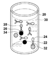
- Embodiment 2 are schematic diagrams showing an outline of an antigen-antibody reaction of the biomolecule detection apparatus according to Embodiment 2 of the present invention.
- Embodiment 2 two types of antibodies are used, and two types of antigens are detected in a uniform solution.
- the antibody 22 and the antibody 26 are placed in the reagent cup 20.
- the antibody 22 and the antibody 26 are labeled with a fluorescent molecule 24 and a fluorescent molecule 28, respectively.
- an antigen 32 that specifically binds to the antibody 22 is present in the specimen, an antigen-antibody reaction occurs between the antibody 22 and the antigen 32, and the antibody 22 And antigen 32 specifically binds.
- an antigen 34 that specifically binds to the antibody 26 is present in the sample, an antigen-antibody reaction occurs between the antibody 26 and the antigen 34, and the antibody 26 and the antigen 34 bind specifically.
- the antibody 22, antigen 32 and fluorescent molecule 24 that have undergone antigen-antibody reaction are referred to as binding molecule 1
- antibody 22 and fluorescent molecule 24 that have not undergone antigen-antibody reaction are referred to as free molecule 1.
- the antibody 26, antigen 34 and fluorescent molecule 28 that have undergone antigen-antibody reaction are referred to as binding molecule 2
- antibody 26 and fluorescent molecule 28 that have not undergone antigen-antibody reaction are referred to as free molecule 2.
- the antigen 32 as the detection target substance is PSA and the antigen 34 is an SCC (Squamous Cell Carcinoma) antigen.
- an anti-PSA antibody that specifically binds to PSA is used as the antibody 22
- an SCC antibody that specifically binds to the SCC antigen is used as the antibody 26.
- Alexa Fluor 568 (trade name of Molecular Probes) was used as the fluorescent molecule 24
- Alexa Fluor 555 (trade name of Molecular Probes) was used as the fluorescent molecule 28.
- Alexa Fluor 555 emits fluorescence having a wavelength of about 540-700 nm, and emits fluorescence having a wavelength of about 570 nm most strongly.
- the biomolecule detection apparatus irradiates a solution containing two types of free molecules and two types of binding molecules with excitation light to detect or quantify the target binding molecules.
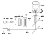
- FIG. 12 is a block diagram showing the main configuration of the biomolecule detection apparatus 200 according to Embodiment 2 of the present invention.
- symbol is attached
- the biomolecule detection apparatus 200 is mainly different from the configuration of the biomolecule detection apparatus 100 shown in Embodiment 1 in a light receiving unit 202, a dispensing unit 204, a reagent tank 206, and a CPU 208.
- the dispensing unit 204 sucks up two types of antibodies from the reagent tank 206 in which a plurality of antibodies are contained in separate containers, and dispenses them into the reagent cup 108.
- the light receiving unit 202 detects the fluorescence generated from the fluorescent molecules in the reagent cup 108, and receives the command (S1) from the CPU 208 and the fluorescence generated from the fluorescent molecules 24 and the fluorescence generated from the fluorescent molecules 28. And can receive light separately.
- the CPU 208 calculates the digital data output from the A / D conversion unit 128 and outputs the result to the display unit 102. Further, the CPU 208 receives an input from the user input unit 104 and issues an instruction command for the operations of the orientation control light source unit 116, the excitation light source unit 118, the dispensing unit 204, the FG 122, and the light receiving unit 202. Specifically, the CPU 208 issues ON / OFF commands to the orientation control light source unit 116 and the excitation light source unit 118, and instructs the dispensing unit 204 to specify a reagent to be used and a dispensing operation. A start command is issued, an instruction command and an output command for a waveform of a voltage signal to be output are given to the FG 122, and a filter switching command is given to the light receiving unit 202.
- FIG. 13 is a schematic diagram illustrating a detailed configuration of the light receiving unit 202 in the biomolecule detection apparatus 200 according to the second embodiment.
- the filter switching unit 210 in the light receiving unit 202 includes two types of filters, a filter 212 and a filter 214.
- the two types of filters are movable, and the filters through which the light condensed and collimated by the lens 142 pass can be switched.
- the fluorescence 216 generated from the fluorescent molecules 14 in the reagent cup 108 and incident on the left side portion of the light receiving unit 202 on the paper surface and the fluorescent light 218 incident on the right side portion of the light receiving unit 202 on the paper surface are collected by the lens 142 and are filtered by the filter 212 or The light enters the polarizer 146 through the filter 214 and enters the PD 150 through the lens 148.
- fluorescence also exists between the fluorescence 216 and the fluorescence 218, and the behavior thereof can be predicted by those skilled in the art, and thus the description thereof is omitted.
- the filter switching unit 210 receives a command from the CPU 208 and switches a filter to be used.
- a light receiving side filter of a SpRed-A filter (trade name of Semirock) set is used as the filter 212.
- the light receiving side filter of the SpRed-A filter set is a bandpass filter that transmits light having a wavelength of about 605 nm to 650 nm.
- a light receiving side filter of a SpOr-A filter (trade name of Semirock) is used as the filter 214.
- the light receiving side filter of the SpOr-A filter set is a bandpass filter that transmits light having a wavelength of about 575 to 600 nm.
- the measurement operation of the biomolecule detection apparatus 200 is basically the same as the measurement operation of the biomolecule detection apparatus 100 described in the first embodiment, but differs in small points. Since the reason why the free molecule and the binding molecule can be detected separately has been described in the first embodiment, here, a method for separating and detecting two types of binding molecules will be described.
- the biomolecule detection apparatus 200 first determines which of the two types of binding molecules is detected first. This can be arbitrarily determined by the user through the user input unit 104 or the like. Here, the binding molecule 1 having Alexa Fluor 568 as a fluorescent molecule is detected first.
- the CPU 208 issues a command to instruct the filter switching unit 210 in the light receiving unit 202 to use the filter 212.
- the filter switching unit 210 receives a command from the CPU 208 and moves the filter 212 to a position where light condensed and collimated by the lens 142 passes.
- the orientation control signal changes to 5 V and excitation light is irradiated toward the reagent cup 108, the fluorescent molecules 24 and the fluorescent molecules 28 in the solution generate fluorescence.
- the fluorescence generated from the fluorescent molecules 24 and 28 is condensed and collimated by the lens 142 and enters the filter 212. Since the filter 212 passes only light having a wavelength of about 605 nm to 650 nm, the fluorescence generated from the fluorescent molecule 24 passes through the filter, and the fluorescence generated from the fluorescent molecule 28 is almost completely blocked by the filter. In this way, the light receiving unit 202 can detect only the fluorescence generated from the fluorescent molecules 24.
- FIG. 14A shows a PD output as a result of measuring the number of cycles of the orientation control signal by the biomolecule detection apparatus 200 and detecting the fluorescence generated from the fluorescent molecules 24.
- a graph is schematically shown for easy calculation.
- the PD output outputs a signal having the same cycle as that of the orientation control signal.
- the lock-in amplifier detects a component synchronized with the period of the orientation control signal from the PD output, and outputs a value S1.
- the CPU 208 calculates the concentration of the binding molecule 1 from the obtained value S1. Specifically, the measured value S1 is converted to the concentration C1 using the calibration curve function f1 (S) as in the first embodiment. The CPU 208 outputs the obtained density C1 to the display unit 102.
- the biomolecule detection apparatus 200 measures the binding molecule 2.
- the CPU 208 issues a command to instruct the filter switching unit 210 in the light receiving unit 202 to use the filter 214.
- the filter switching unit 210 receives a command from the CPU 208 and moves the filter 214 to a position where light condensed and collimated by the lens 142 passes. Since the filter 214 passes only light having a wavelength of about 575 nm to 600 nm, the fluorescence generated from the fluorescent molecule 24 is blocked by the filter, and the fluorescence generated from the fluorescent molecule 28 passes through the filter. In this way, the light receiving unit 202 can detect only the fluorescence generated from the fluorescent molecules 28.
- FIG. 14B shows a PD output as a result of measuring the number of cycles of the orientation control signal by the biomolecule detection apparatus 200 and detecting the fluorescence generated from the fluorescent molecules 28.
- a graph is schematically shown for easy calculation.
- the PD output outputs a signal having the same cycle as that of the orientation control signal.
- the switching timing of the orientation control signal when measuring the binding molecule 2 is different from that when measuring the binding molecule 1. This is because the binding molecule 1, the free molecule 1, the binding molecule 2 and the free molecule 2 have different volumes and molecular weights, so that the time required for each molecule to complete the switching of the orientation is different.
- the timing at which the increase and decrease of the PD output are switched is the same, but the maximum value and the minimum value of the PD output are changed. Are different from each other. This is caused by the difference in concentration between the binding molecule 1 and the binding molecule 2 in the solution and the difference in concentration between the free molecule 1 and the free molecule 2 in the solution.
- the CPU 208 obtains the concentration of the binding molecule 2 from the obtained value S2. Specifically, the measured value S2 is converted into the concentration C2 using the calibration curve function f2 (S). The CPU 208 outputs the obtained density C2 to the display unit 102.
- the biomolecule detection apparatus 200 in addition to the configuration of the biomolecule detection apparatus 100 described in Embodiment 1, it specifically binds to the detection target substance.
- Two types of antibodies and fluorescent molecules were used as substances, and the filter switching unit 210 was configured to be able to switch between two types of filters. Therefore, by using a filter corresponding to the fluorescent molecule associated with the binding molecule containing the detection target substance, only the fluorescence generated from the fluorescent molecule accompanying the binding molecule containing the detection target substance can be detected. The concentrations of the two types of detection target substances contained in the specimen can be accurately measured.
- Alexa Fluor 568 and Alexa Fluor 555 are used as fluorescent molecules, but the fluorescent molecules are not limited to these.
- a plurality of substances that specifically bind to each of the plurality of detection target substances may be labeled with a plurality of fluorescent molecules that have different fluorescence wavelengths, excitation wavelengths, or fluorescence lifetimes to such an extent that they can be separated by a filter.
- the detection target substance and the substance that specifically binds to the detection target substance is not limited thereto.
- the present invention can be applied to the detection of an antibody using an antigen, a nucleic acid that hybridizes with a specific nucleic acid and the nucleic acid, a nucleic acid and a nucleic acid-binding protein, a ligand and a receptor, a sugar and a lectin, a protease detection, a higher-order structure It can also be applied to changes and the like.
- the case where there are two types of detection target substances has been described.
- the number of detection target substances may be larger.
- a plurality of substances that specifically bind to each of the plurality of detection target substances are used, the plurality of substances are labeled with a plurality of different fluorescent molecules, and fluorescence generated from each fluorescent molecule is emitted.
- the respective detection target substances can be separated from each other and detected.
- the types of detection target substances increase, the types of fluorescent molecules also increase, and a plurality of fluorescences generated from a plurality of fluorescent molecules will be mixed, so it may be difficult to separate the fluorescence only with a filter. .
- separation of fluorescence can be facilitated by increasing the types of excitation light.
- the absorbance of the fluorescent molecule depends on the wavelength of the excitation light, and there is a wavelength band that is easily absorbed for each type of fluorescent molecule. Therefore, by changing the wavelength of the excitation light, only some of the fluorescent molecules generate fluorescence, and the separation of the fluorescence with the filter becomes easy. Further, by using a bandpass filter having a narrower pass band, it is possible to easily detect fluorescence generated from the target fluorescent molecule.
- a filter is used as a spectroscopic means for dispersing light in the light receiving unit, but it is not always necessary to use a filter.
- light may be dispersed using a diffraction grating or a prism, and only light having a specific wavelength may be received by a photodiode.
- the switching of the orientation of the binding molecules in the solution is not limited to using a laser, and a magnetic method or an electrical method may be used as long as only the binding molecules can be oriented.
- the irradiation direction of the orientation control light does not necessarily have to be switched by AOD.
- the orientation control light irradiation direction may be switched by providing a plurality of alignment control light source units and switching the light source itself, or the orientation control light irradiation direction may be switched using a drive mirror or the like.
- the alignment molecules are aligned using a linearly polarized laser as the alignment control light, and the liquid crystal phase modulation device that can be controlled by a ⁇ / 2 wavelength plate or an electric signal is used to switch the direction in which the laser is linearly polarized.
- the orientation direction of molecules may be switched.
- the traveling direction of the orientation control light 117 is a direction in which the direction of the transition moment of the fluorescent molecule associated with the binding molecule and the vibration direction of the linearly polarized excitation light are parallel to each other
- the irradiation direction of the orientation control light is alternately switched in two directions orthogonal to each other, in which the direction of the transition moment of the fluorescent molecule associated with the binding molecule and the vibration direction of the linearly polarized excitation light are perpendicular to each other. It is not always necessary to switch between the two directions orthogonal to each other.
- one of the two irradiation directions of the orientation control light to be set is the direction of the transition moment of the fluorescent molecule associated with the binding molecule and the vibration direction of the excitation light linearly polarized And the direction in which the excitation light that is linearly polarized cannot excite the fluorescent molecule is sufficient.
- the fluorescent molecules are oriented in a direction in which the excitation light cannot excite the fluorescent molecules, no fluorescence is generated, so that the PD output is only the output due to some free molecules and noise caused by the device.
- the time required to complete the switching of the orientation of the binding molecule is maximized, and the S / N is the best.
- the angle formed by the two directions in which the orientation control light 117 travels is 60 degrees
- the switching of the orientation of the binding molecule is completed as compared with the case where the two travel directions of the orientation control light 117 are orthogonal to each other.
- the time required until the time is shortened, and the time required for the measurement is also shortened.
- the angle formed by the two directions in which the orientation control light 117 travels is smaller than 90 degrees, the time required to complete the switching of the orientation of the binding molecule is shortened, and the measurement time is also shortened.
- orientation direction of the orientation control light 117 may be switched alternately, and the direction of the transition moment of the fluorescent molecule associated with the binding molecule and the vibration direction of the linearly polarized excitation light are not necessarily included. Also good. If there is a time difference in switching the orientation of the binding molecule, the difference appears in the fluorescence data, so the presence of the binding molecule can be confirmed.
- the number of reagent cups is not necessarily one, and a plurality of reagent cups are provided in the apparatus. It is good also as a structure which can provide and can set a some sample. In that case, if the apparatus is configured to perform the measurement by sequentially moving the reagent cups to the measurement position, a plurality of specimens can be automatically measured.
- an example using an antibody labeled with a fluorescent molecule has been described.
- the antibody and antigen binding and the antibody and fluorescent molecule binding may be performed simultaneously in the reagent cup.
- the user prepares the antibody and the fluorescent molecule in separate reagent tanks, and at the time of measurement, the biomolecule detection device dispenses the antibody, the fluorescent molecule, and the specimen into the respective reagent cups and causes them to react.
- orientation control light source unit 116 and the excitation light source unit 118 may be detachable and may be replaced with appropriate ones according to the detection target substance, fluorescent molecules, and the like.
- the predetermined time interval for switching the direction of orientation control is based on the molecular weight or volume of each of the detection target substance, the substance that specifically binds to the detection target substance and the fluorescent molecule, and the strength of the external force of the orientation control means. It is desirable to obtain the time required to complete the switching of the orientation of the binding molecule and set that time as a predetermined time interval. In such a case, even after the switching of the orientation of all the binding molecules is completed, the orientation control light is not irradiated in the same direction, and the power consumption can be reduced. Further, the measurement is not continued until unnecessary, and the measurement time can be shortened.
- the time required to complete the switching of the orientation of all binding molecules may be obtained based on the PD output or the A / D converter output. For example, if you repeat the measurement for several cycles, you can roughly know how long it will take for each output to saturate. The time interval may be determined.
- each molecule When controlling the orientation of molecules by orientation control light, a complicated mechanism is not required compared to controlling the orientation of molecules by magnetic force or the like. For example, in order to control the orientation of molecules using magnetic force, each molecule must have magnetism or it is necessary to prepare a molecule with magnetism and bind it to the molecule whose orientation is to be controlled. Preparation for measurement is complicated.
- the sample is not limited to plasma separated from whole blood, and the detection target substance is dispersed in the solution. If so, body fluids such as urine and sputum can be used as the specimen.
- the binding molecules are oriented and the free molecules are not oriented has been described as an example.
- the free molecules are not necessarily oriented. Even when free molecules are oriented by the orientation control light, the free molecules and the binding molecules have different volumes and molecular weights, and the orientation speeds are different. For this reason, even when the irradiation direction of the orientation control light is switched, the time required for completing the switching of the orientation of these molecules is different from each other, and therefore the periods in which fluorescence is generated are also different. Therefore, if a reference signal is input to the lock-in amplifier that takes twice the time required for switching the orientation of the binding molecule after the orientation control signal is switched, it will be generated from the fluorescent molecule associated with the binding molecule.
- the fluorescent component to be detected can be detected.
- measurement can be performed in a liquid phase in which an antigen, an antibody, and a fluorescent molecule are dispersed in a liquid.
- pretreatment is simple.
- the antigen and free molecules are not fixed to the solid phase, the antigen and free molecules can freely move around in the solution, and there is an advantage that the reaction is faster than the measurement in the solid phase.
- each embodiment according to the present invention does not examine changes in the degree of polarization of fluorescence due to changes in Brownian motion as in the conventional fluorescence polarization method, so that the components of the specimen affect the fluorescence lifetime of the fluorescent molecule. Even if given, it has little effect on the measurement.
- the case where the solution is irradiated with the excitation light 119 linearly polarized in one direction that is, the case where the solution is irradiated with the excitation light 119 having a single polarization plane is described.
- the excitation light 119 does not necessarily need to be linearly polarized light having a single polarization plane.
- the excitation light 119 only needs to have at least one linearly polarized light component in a specific direction.
- the light having a linearly polarized light component in a specific direction means that the relationship between the direction of the transition moment of the fluorescent molecule and the vibration direction of the linearly polarized light component of the excitation light changes due to the change in the orientation direction of the fluorescent molecule,
- it may be configured to irradiate randomly polarized excitation light and provide an analyzer in front of the light receiving unit so as to receive only linearly polarized light components in a specific direction from the fluorescence generated from the fluorescent molecules.
- the random polarization means that the vibration direction of light is random, and linearly polarized light components that vibrate in various directions exist.
- 15A and 15B are conceptual diagrams showing the orientation direction of the fluorescent molecules 14 and the vibration direction of the randomly polarized excitation light 230 when irradiated with the orientation control lights 136 and 134, respectively.
- the vibration directions 232a to 232d of the excitation light 230 represent the vibration directions of light in a plane perpendicular to the traveling direction of the excitation light 230.
- 15A and 15B show that the vibration directions of the excitation light 230 are various directions depending on the vibration directions 232a to 232d.
- the illustrated components but also more components in all angular directions are present. include.
- the fluorescent molecule when a fluorescent molecule stationary in a solution is excited with linearly polarized excitation light, the fluorescent molecule generates fluorescence polarized in the same direction as the polarization direction of the excitation light.
- the randomly polarized fluorescence 234 is also generated from the fluorescent molecules 14 associated with the binding molecules.
- the analyzer 236 transmits a component that vibrates in a specific direction among the randomly polarized fluorescence 234 generated from the fluorescent molecules 14 and blocks a component that vibrates in the other direction.
- the light transmitted through the analyzer 236 becomes light that vibrates only in a specific direction.
- the component of the fluorescence 234 that vibrates in a specific direction that can pass through the analyzer 236 is a component that vibrates in the vibration direction 232a. Therefore, the vibration direction of the fluorescence 234 that has passed through the analyzer 236 is only the vibration direction 232a in FIGS. 15A and 15B.
- the component that vibrates in the vibration direction 232 a included in the fluorescence 234 is generated by being excited by the excitation light component linearly polarized in the vibration direction 232 a of the excitation light 230. That is, only the fluorescent component generated by being excited by the excitation light component linearly polarized in the vibration direction 232 a included in the excitation light 230 can reach the photodiode 238. Therefore, with such a configuration, even when randomly polarized light is used as the excitation light 230, the same measurement as that in Embodiment 1 in which measurement is performed using excitation light that vibrates in a specific direction is performed. Can do.
- the component of the fluorescence 234 that vibrates in a specific direction transmitted by the analyzer 236 is not necessarily limited to the component that vibrates in the direction shown here, and excitation of the fluorescent molecule 14 with a change in the orientation direction of the fluorescent molecule 14. Any component that causes a difference in efficiency may be used.
- 15A and 15B show an example in which the amplitude is constant when the excitation light 230 vibrates in any direction, but the amplitude does not necessarily have to be constant in all directions. Since the component of the fluorescence 234 received by the photodiode 238 is only a component that vibrates in a specific direction among the randomly polarized fluorescence 234, components that vibrate in other directions are blocked.
- the orientation control signal when the orientation control signal is 0 V, the direction of the transition moment of the fluorescent molecules 14 oriented by the orientation control light 136 and the vibration direction of the light that can pass through the analyzer 236 are perpendicular to each other. In this case, the excitation efficiency of the fluorescent molecule 14 due to the component that vibrates in the vibration direction 232a included in the excitation light 230 is minimized. Therefore, the component that reaches the photodiode 238 through the analyzer 236 in the fluorescence 234 generated from the fluorescent molecule 14 is minimized.
- the orientation control signal is 5 V
- the direction of the transition moment of the fluorescent molecules 14 oriented by the orientation control light 134 and the vibration direction of the light that can pass through the analyzer 236 are parallel.
- the excitation efficiency of the fluorescent molecule 14 by the component that vibrates in the vibration direction 232a included in the excitation light 230 is maximized. Therefore, the component that reaches the photodiode 238 through the analyzer 236 among the fluorescence 234 generated from the fluorescent molecules 14 is maximized.
- the orientation direction of the fluorescent molecule 14 changes, and the direction of the transition moment of the fluorescent molecule 14 and the light that can be transmitted through the analyzer 236 are changed.
- the direction of vibration gradually approaches parallel.
- the excitation efficiency of the fluorescent molecule 14 due to the component included in the excitation light 230 that vibrates in the direction that can pass through the analyzer 236 increases, and the component of the fluorescence 234 generated from the fluorescent molecule 14
- the component which vibrates in the direction which can be transmitted increases. That is, the fluorescence intensity detected by the photodiode 238 gradually increases as in the first embodiment.
- the fluorescence intensity received by the photodiode 238 is changed by switching only the orientation of the binding molecule 15 with the switching of the orientation control light. Therefore, even in the case of such a configuration, the graph of the photodiode output with respect to time when the orientation control signal is changed from 0 V to 5 V has the same shape as FIG. 10A. That is, also in this case, the concentration of the detection target substance can be measured by performing the same calculation as that of the first embodiment on the graph of the photodiode output.
- excitation light 240 having only two components that are linearly polarized in two directions orthogonal to each other may be used.
- the excitation light 240 has only two components each linearly polarized in the vibration directions 242a and 242b in a plane perpendicular to the traveling direction. That is, the vibration direction 242a and the vibration direction 242b are orthogonal to each other.
- the fluorescent molecules 14 excited by such excitation light 240 emit fluorescence 244 having a component that vibrates in the same direction as the vibration direction of the excitation light 240. That is, the fluorescent light 244 has two components each linearly polarized in the vibration directions 242a and 242b.
- FIG. 16A is a conceptual diagram when the orientation control signal is 0V.
- the orientation control light 136 is emitted.
- the fluorescent molecules 14 irradiated with the alignment control light 136 are aligned so that the direction of the transition moment is the same as the vibration direction 242b. That is, the direction of the transition moment of the fluorescent molecule 14 when the orientation control signal is 0 V and the vibration direction 242b of one component of the excitation light 240 are parallel to each other.
- the polarization beam splitter 246 transmits the linearly polarized light component 244a that vibrates in the vibration direction 242a of the fluorescence 244, and reflects the linearly polarized light component 244b that vibrates in the vibration direction 242b.
- the linearly polarized light component 244 a of the fluorescence 244 that has passed through the polarization beam splitter 246 reaches the photodiode 248.
- the linearly polarized component 244 b of the fluorescence 244 reflected by the polarization beam splitter 246 reaches the photodiode 250.
- FIG. 16B is a conceptual diagram when the orientation control signal is 5V.
- the orientation control signal is 5V
- the orientation control light 134 is emitted.
- the fluorescent molecules 14 irradiated with the alignment control light 134 are aligned so that the direction of the transition moment is the same as the vibration direction 242a. That is, when the orientation control signal is 5 V, the direction of the transition moment of the fluorescent molecule 14 and the vibration direction 242a of the other component of the excitation light 240 are parallel to each other.
- the linearly polarized light component 244a of the fluorescent light 244 that has passed through the polarizing beam splitter 246 is the same as that in the first embodiment.
- the time change of the output of the photodiode 248 is a graph similar to the graph shown in FIG. 10A described in the first embodiment. That is, as the orientation direction of the orientation control light is changed, the orientation direction of the binding molecules starts to change, and the output of the photodiode 248 increases.
- the output of the photodiode 248 reaches the maximum value.
- the orientation control signal becomes 0V after the output of 5V continues for T seconds.
- the orientation control signal is switched from 5V to 0V, the orientation direction of the binding molecule is switched again, and the output of the photodiode 248 decreases.
- the amount of the linearly polarized component 244b of the fluorescence 244 is maximum, and therefore the output of the photodiode 250 that receives the linearly polarized component 244b of the fluorescence 244 reflected by the polarization beam splitter 246. But it will be the maximum until then.
- the orientation control light irradiation direction the orientation direction of the binding molecules begins to switch, and the output of the photodiode 250 decreases. Then, at the time when the switching of the orientation of all the binding molecules is completed, the output of the photodiode 250 becomes the minimum value.
- the orientation control signal becomes 0V after the output of 5V continues for T seconds.
- the orientation control signal When the orientation control signal is switched from 5V to 0V, the orientation direction of the binding molecule is switched again, and the output of the photodiode 250 increases. This is because the vibration direction 242b of the other component of the excitation light 240 and the transition moment direction of the fluorescent molecule 14 return to a parallel state.
- the received light data is normalized.
- the received light data is normalized.
- the concentration of the binding molecule is calculated from the normalized light reception data.
- the concentration of the binding molecule is obtained based on the value of the saturated fluorescence intensity, but it is not always necessary to obtain it by such a method.
- lock-in detection may be performed using such a high frequency that the irradiation direction of the orientation control light returns to the original value before the fluorescence intensity is saturated after switching the orientation direction of the orientation control light.
- FIG. 17A is a graph showing the output of an orientation control signal for which the orientation control signal is 5 V long enough to saturate the fluorescence intensity, and the fluorescence intensity detected using the orientation control signal.
- 17B is a graph showing the output of an orientation control signal with a short period during which the orientation control signal is 5 V so that the fluorescence intensity is not saturated, and the fluorescence intensity detected using the orientation control signal.
- the period t1 of the orientation control signal is sufficiently long and the period during which the orientation control signal is 5 V is long, all the binding molecules are oriented and the fluorescence intensity becomes the maximum value, and the output of the lock-in amplifier Becomes the maximum value i1.
- FIG. 17A since the period t1 of the orientation control signal is sufficiently long and the period during which the orientation control signal is 5 V is long, all the binding molecules are oriented and the fluorescence intensity becomes the maximum value, and the output of the lock-in amplifier Becomes the maximum value i1.
- FIG. 17A since the period t1
- the number of orientation control light source units is not necessarily one for one irradiation direction, and a plurality of orientation control light source units are provided, and a plurality of orientation control light source units are provided in the same direction. You may irradiate alignment control light.
- each optical system that controls the direction of the transition moment of the fluorescent molecule by changing the direction in which the orientation control light is irradiated as in each of the embodiments according to the present invention the beam diameter of the orientation control light is narrowed down.
- multiple stages of optical systems are prepared to broaden the irradiation range by simultaneously irradiating multiple points of orientation control light from a certain direction. You may do it.
- the multi-stage optical system may have a plurality of optical paths at least before the alignment control light enters the reagent cup.
- the orientation control light is emitted from each of the three orientation control light source sections, and the orientation control light is emitted to three points from a certain direction to the reagent cup. it can.
- the orientation control light can be irradiated at a plurality of points corresponding to the branched portion.
- the alignment control light can be simultaneously irradiated to multiple points, and the transition moments of the fluorescent molecules can be rotated at a plurality of locations.
- the direction of the transition moment of the fluorescent molecule is controlled by switching the direction in which the orientation control light is irradiated.
- the method of controlling the direction of the transition moment of the fluorescent molecule is described. Is not limited to this. For example, even if the transition moment of the fluorescent molecule is controlled by controlling the vibration direction of the linearly polarized orientation control light by utilizing the phenomenon that the transition moment of the fluorescent molecule follows the vibration direction of the linearly polarized light, Good.
- the polarization axis of the orientation control light is changed.
- the binding molecules irradiated with the linearly polarized alignment control light are aligned in a specific direction determined by the polarization axis of the alignment control light.
- the polarization axis of the linearly polarized orientation control light can be controlled by using a ⁇ / 2 wavelength plate.
- the ⁇ / 2 wavelength plate is a phase plate having a function of setting the optical path difference between two orthogonal components of light to 1 ⁇ 2 wavelength, and is used to rotate the polarization axis of light.
- Light linearly polarized in a direction parallel to the optical axis direction of the ⁇ / 2 wavelength plate passes through the ⁇ / 2 wavelength plate, but is linearly polarized in a direction that forms an angle of 45 degrees with the optical axis direction of the ⁇ / 2 wavelength plate.
- Light is transmitted with the polarization axis rotated by 90 degrees.
- the orientation control light is passed through and the orientation control light is transmitted by rotating the polarization axis of the orientation control light by 90 degrees.
- the binding molecules can be oriented in two directions by rotating the polarization axis of the orientation control light linearly polarized using the ⁇ / 2 wavelength plate.
- the binding molecule 354 located on the rotation axis (the rotation center of the polarization axis 352) immediately follows the rotation of the polarization axis 352. Then rotate.
- the binding molecules 356 positioned at the peripheral edge of the orientation control light 350 cannot immediately follow the rotation of the polarization axis 352 and are separated from the polarization axis 352. After a while, the binding molecule 356 is also drawn into the orientation control light 350 and starts to rotate following the rotation of the polarization axis 352.
- the movement of the binding molecule 354 located on the rotation axis is a behavior that rotates in synchronization with the rotation of the polarization axis 352 of the orientation control light 350, but the binding molecule 356 located at the peripheral edge of the orientation control light 350 The movement does not synchronize with the rotation of the polarization axis 352 of the orientation control light 350 and revolves around the rotation axis.
- the orientation control light is simultaneously incident on multiple points from a predetermined direction. For example, as shown in FIG. 19 (top view of the reagent cup 108), nine orientation control lights respectively corresponding to nine points 360a to 360i may be incident on the reagent cup 108. In this way, the number of binding molecules positioned at the center of the polarization axis of the orientation control light increases, so that the influence on the measurement can be reduced.
- the number of points on which the orientation control light is simultaneously incident is not limited to nine points, and may be more or less than nine points. It is desirable to make the light incident on more points as the orientation control light is reduced. Thereby, the binding molecule can be rotated in synchronization with the rotation of the orientation control light at a plurality of locations. As a result, sudden fluctuations in fluorescence intensity can be reduced, and the coefficient of variation (Coefficient of Variation), which is an index representing relative dispersion, can be improved.
- FIG. 20 shows the structure of the orientation control light source unit 402 for allowing the orientation control light to enter multiple points simultaneously from a predetermined direction.
- the orientation control light source unit 402 is a 3 ⁇ 3 two-dimensional laser array.
- the orientation control light source unit 402 emits light from nine light emitting points 404a to 404i.
- the size of the light emitting point is 1 ⁇ m in the vertical direction and 100 ⁇ m in the horizontal direction.
- the distance between the light emitting points is about 100 ⁇ m.
- FIG. 21 shows an example of an optical system using the orientation control light source unit 402 shown in FIG.
- components other than the optical system of the orientation control light and the excitation light are omitted.
- the linearly polarized orientation control light 422 output from the orientation control light source unit 402 passes through the collimator lens 406 and becomes a parallel light beam at the focal point.
- the orientation control light 422 that has passed through the collimator lens 406 is incident on the ⁇ / 2 wavelength plate 412 through the beam expander 408 and the beam expander 410.
- the orientation control light 422 that has passed through the beam expander 408 and the beam expander 410 is spread into a parallel light beam having a specific magnification.
- the ⁇ / 2 wavelength plate 412 is on the rotary stage and is rotatable. Thereby, the vibration direction of the orientation control light 422 can be rotated.
- the orientation control light 422 transmitted through the ⁇ / 2 wavelength plate 412 is reflected by the dichroic mirror 418, collected by the lens 420, and incident upward from the bottom surface of the reagent cup 108.
- the excitation light 424 output from the light source unit 414 passes through the lens 426 and is reflected by the dichroic mirror 416.
- the excitation light 424 reflected by the dichroic mirror 416 passes through the dichroic mirror 418, is collected by the lens 420, and enters upward from the bottom surface of the reagent cup 108.
- the magnification is 1.29 times. Therefore, on the bottom surface of the reagent cup 108, the size of the orientation control light 422 is about 1.3 ⁇ m ⁇ 130 ⁇ m, and the pitch is about 129 ⁇ m.
- FIG. 22 As well, components other than the optical system of the orientation control light and the excitation light are omitted.
- the same components as those in FIG. 21 are denoted by the same reference numerals, and the description thereof is omitted.
- the orientation control light source unit 116 is the same as that in the first embodiment.
- the orientation control light 432 passes through the collimator lens 406, the beam expander 408, and the beam expander 410 and enters the microlens array 428.
- the microlens array 428 has a plurality of microlenses 428a arranged in a lattice pattern.
- the orientation control light 432 that has passed through the microlens array 428 becomes a plurality of light beams that are focused at different positions, like light emitted from a plurality of light sources.
- the orientation control light 432 is focused by the pinhole array 430, reflected by the dichroic mirror 418, and incident upward from the bottom surface of the reagent cup 108 through the lens 420. As described above, even when the microlens array is used, the orientation control light can be simultaneously incident on multiple points from a predetermined direction.
- the reagent cup has a cylindrical shape, but the reagent cup does not necessarily have a cylindrical shape.
- a reagent cup 432 having a quadrangular prism shape and having a quadrangular prism-shaped solution holding portion inside may be used.
- the reagent cup 432 having such a quadrangular column-shaped solution holding portion is particularly suitable for pressing binding molecules against the inner side wall surface of the reagent cup 432 using the pressure of the alignment control light acting in the traveling direction of the alignment control light. ing. This is a phenomenon that occurs when the mass of the binding molecule is light, and is caused by the binding molecule moving in the solution under the pressure of the orientation control light.
- the binding molecules are oriented while being pressed against the interface between the solution and the reagent cup 432.
- the interface is flat and the pressure by the orientation control light acts in a direction perpendicular to the interface, the binding molecule moves in a direction parallel to the interface and goes out of the irradiation range of the orientation control light. There is no.
- FIG. 25 is a diagram illustrating an example of the positional relationship between the focus of the focused orientation control light and the reagent cup.
- the orientation control light 434 enters the lens 436 and forms a focal point 434a at the interface between the plasma 16 and the side wall part 432b of the reagent cup (the inner side wall surface of the side wall part 432b). Since the intensity of the orientation control light 434 is strongest at the position of the focal point 434a of the orientation control light 434, the binding molecules can be pressed with a stronger pressure.
- the binding molecules can be more efficiently oriented while pressing the binding molecules against the inner side wall surface of the side wall portion 432b at the position of the focal point 434a. Also in this case, the orientation direction of the binding molecule can be changed at the position of the focal point 434a by rotating the vibration direction of the linearly polarized orientation control light 434.
- the solution holding portion does not necessarily have a quadrangular prism shape, and it is sufficient that the solution holding portion has a flat surface on at least one surface.
- the biomolecule detection apparatus and the biomolecule detection method according to the present invention perform detection or quantification of a detection target substance using, for example, an interaction between a detection target substance and a substance that specifically binds to the detection target substance. It can be used for a device to perform.
Landscapes
- Health & Medical Sciences (AREA)
- Immunology (AREA)
- Life Sciences & Earth Sciences (AREA)
- Chemical & Material Sciences (AREA)
- Physics & Mathematics (AREA)
- Engineering & Computer Science (AREA)
- Analytical Chemistry (AREA)
- Biochemistry (AREA)
- General Health & Medical Sciences (AREA)
- General Physics & Mathematics (AREA)
- Pathology (AREA)
- Biomedical Technology (AREA)
- Nuclear Medicine, Radiotherapy & Molecular Imaging (AREA)
- Molecular Biology (AREA)
- Hematology (AREA)
- Urology & Nephrology (AREA)
- Biotechnology (AREA)
- Cell Biology (AREA)
- Microbiology (AREA)
- Food Science & Technology (AREA)
- Medicinal Chemistry (AREA)
- Chemical Kinetics & Catalysis (AREA)
- Optics & Photonics (AREA)
- Investigating, Analyzing Materials By Fluorescence Or Luminescence (AREA)
Priority Applications (3)
| Application Number | Priority Date | Filing Date | Title |
|---|---|---|---|
| EP20110828446 EP2623959A4 (de) | 2010-09-30 | 2011-09-29 | Vorrichtung zur erkennung von biomolekülen und verfahren zur erkennung von biomolekülen |
| CN201180047234.6A CN103140751B (zh) | 2010-09-30 | 2011-09-29 | 生物分子检测设备和生物分子检测方法 |
| US13/854,640 US8680486B2 (en) | 2010-09-30 | 2013-04-01 | Biological molecule detecting apparatus and biological molecule detecting method |
Applications Claiming Priority (4)
| Application Number | Priority Date | Filing Date | Title |
|---|---|---|---|
| JP2010222999 | 2010-09-30 | ||
| JP2010-222999 | 2010-09-30 | ||
| JP2011123101A JP5685492B2 (ja) | 2010-09-30 | 2011-06-01 | 生体分子検出装置および生体分子検出方法 |
| JP2011-123101 | 2011-06-01 |
Related Child Applications (1)
| Application Number | Title | Priority Date | Filing Date |
|---|---|---|---|
| US13/854,640 Continuation US8680486B2 (en) | 2010-09-30 | 2013-04-01 | Biological molecule detecting apparatus and biological molecule detecting method |
Publications (1)
| Publication Number | Publication Date |
|---|---|
| WO2012042880A1 true WO2012042880A1 (ja) | 2012-04-05 |
Family
ID=45892369
Family Applications (1)
| Application Number | Title | Priority Date | Filing Date |
|---|---|---|---|
| PCT/JP2011/005487 Ceased WO2012042880A1 (ja) | 2010-09-30 | 2011-09-29 | 生体分子検出装置および生体分子検出方法 |
Country Status (5)
| Country | Link |
|---|---|
| US (1) | US8680486B2 (de) |
| EP (1) | EP2623959A4 (de) |
| JP (1) | JP5685492B2 (de) |
| CN (1) | CN103140751B (de) |
| WO (1) | WO2012042880A1 (de) |
Cited By (1)
| Publication number | Priority date | Publication date | Assignee | Title |
|---|---|---|---|---|
| WO2012133048A1 (ja) * | 2011-03-31 | 2012-10-04 | 富士フイルム株式会社 | 生体分子検出装置および生体分子検出方法 |
Families Citing this family (5)
| Publication number | Priority date | Publication date | Assignee | Title |
|---|---|---|---|---|
| JP5703126B2 (ja) * | 2010-09-30 | 2015-04-15 | 富士フイルム株式会社 | 生体分子検出装置および生体分子検出方法 |
| JP5562886B2 (ja) * | 2011-03-18 | 2014-07-30 | 株式会社日立製作所 | 生体分子計測システム及び生体分子計測方法 |
| US20160033408A1 (en) * | 2013-08-30 | 2016-02-04 | Panasonic Intellectual Property Management Co., Ltd. | Detecting apparatus |
| CN106546537B (zh) * | 2016-11-01 | 2019-12-10 | 深圳大学 | 一种蛋白质特征识别的检测装置及其检测方法 |
| CN119044929B (zh) * | 2024-08-07 | 2026-01-06 | 无锡阜时科技有限公司 | 发射模组及其驱动控制方法、光电检测装置及电子设备 |
Citations (8)
| Publication number | Priority date | Publication date | Assignee | Title |
|---|---|---|---|---|
| JPS61272637A (ja) * | 1985-05-29 | 1986-12-02 | Hitachi Ltd | けい光偏光測定装置 |
| JPS6238346A (ja) * | 1985-08-14 | 1987-02-19 | Hitachi Ltd | 蛍光偏光測定装置 |
| JPH07120397A (ja) | 1993-08-31 | 1995-05-12 | Daikin Ind Ltd | 光学的測定装置およびその方法 |
| JPH10104079A (ja) * | 1996-09-25 | 1998-04-24 | Bunshi Bio Photonics Kenkyusho:Kk | 偏光解消イメージング装置 |
| JP2000019172A (ja) * | 1998-07-03 | 2000-01-21 | Matsushita Electric Ind Co Ltd | 多波長蛍光偏光法 |
| WO2003024586A1 (fr) * | 2001-09-14 | 2003-03-27 | National Institute Of Advanced Industrial Science And Technology | Procede et dispositif de controle de l'orientation moleculaire |
| JP2003315258A (ja) * | 2002-04-23 | 2003-11-06 | Aisin Seiki Co Ltd | 微小物質誘導装置 |
| JP2008298743A (ja) | 2007-06-04 | 2008-12-11 | Olympus Corp | 蛍光分析による分子間相互作用検出方法 |
Family Cites Families (4)
| Publication number | Priority date | Publication date | Assignee | Title |
|---|---|---|---|---|
| US5639668A (en) * | 1995-09-14 | 1997-06-17 | Boehringer Mannheim Corporation | Optical apparatus for performing an immunoassay |
| JP5734091B2 (ja) * | 2010-06-04 | 2015-06-10 | 富士フイルム株式会社 | 生体分子検出装置および生体分子検出方法 |
| JP5703126B2 (ja) * | 2010-09-30 | 2015-04-15 | 富士フイルム株式会社 | 生体分子検出装置および生体分子検出方法 |
| JP2012093338A (ja) * | 2010-09-30 | 2012-05-17 | Fujifilm Corp | 生体分子検出装置および生体分子検出方法 |
-
2011
- 2011-06-01 JP JP2011123101A patent/JP5685492B2/ja not_active Expired - Fee Related
- 2011-09-29 WO PCT/JP2011/005487 patent/WO2012042880A1/ja not_active Ceased
- 2011-09-29 EP EP20110828446 patent/EP2623959A4/de not_active Withdrawn
- 2011-09-29 CN CN201180047234.6A patent/CN103140751B/zh not_active Expired - Fee Related
-
2013
- 2013-04-01 US US13/854,640 patent/US8680486B2/en not_active Expired - Fee Related
Patent Citations (8)
| Publication number | Priority date | Publication date | Assignee | Title |
|---|---|---|---|---|
| JPS61272637A (ja) * | 1985-05-29 | 1986-12-02 | Hitachi Ltd | けい光偏光測定装置 |
| JPS6238346A (ja) * | 1985-08-14 | 1987-02-19 | Hitachi Ltd | 蛍光偏光測定装置 |
| JPH07120397A (ja) | 1993-08-31 | 1995-05-12 | Daikin Ind Ltd | 光学的測定装置およびその方法 |
| JPH10104079A (ja) * | 1996-09-25 | 1998-04-24 | Bunshi Bio Photonics Kenkyusho:Kk | 偏光解消イメージング装置 |
| JP2000019172A (ja) * | 1998-07-03 | 2000-01-21 | Matsushita Electric Ind Co Ltd | 多波長蛍光偏光法 |
| WO2003024586A1 (fr) * | 2001-09-14 | 2003-03-27 | National Institute Of Advanced Industrial Science And Technology | Procede et dispositif de controle de l'orientation moleculaire |
| JP2003315258A (ja) * | 2002-04-23 | 2003-11-06 | Aisin Seiki Co Ltd | 微小物質誘導装置 |
| JP2008298743A (ja) | 2007-06-04 | 2008-12-11 | Olympus Corp | 蛍光分析による分子間相互作用検出方法 |
Cited By (1)
| Publication number | Priority date | Publication date | Assignee | Title |
|---|---|---|---|---|
| WO2012133048A1 (ja) * | 2011-03-31 | 2012-10-04 | 富士フイルム株式会社 | 生体分子検出装置および生体分子検出方法 |
Also Published As
| Publication number | Publication date |
|---|---|
| CN103140751B (zh) | 2014-04-09 |
| CN103140751A (zh) | 2013-06-05 |
| JP5685492B2 (ja) | 2015-03-18 |
| EP2623959A4 (de) | 2014-07-30 |
| US20130224764A1 (en) | 2013-08-29 |
| EP2623959A1 (de) | 2013-08-07 |
| JP2012093339A (ja) | 2012-05-17 |
| US8680486B2 (en) | 2014-03-25 |
Similar Documents
| Publication | Publication Date | Title |
|---|---|---|
| JP5734091B2 (ja) | 生体分子検出装置および生体分子検出方法 | |
| JP5703098B2 (ja) | 生体分子検出装置および生体分子検出方法 | |
| US10724957B2 (en) | Micro-droplet fluorescence detection system | |
| JP5685492B2 (ja) | 生体分子検出装置および生体分子検出方法 | |
| US8618508B2 (en) | Detection system and method | |
| JP5703126B2 (ja) | 生体分子検出装置および生体分子検出方法 | |
| CN204462172U (zh) | 一种全自动高通量多色荧光免疫层析芯片分析系统 | |
| JP6991972B2 (ja) | 検出チップ、検出システムおよび検出方法 | |
| CN111208114A (zh) | 表面增强拉曼散射/荧光结合spr传感的检测方法及装置 | |
| CN104849481A (zh) | 一种全自动高通量光学生物传感装置 | |
| CN103913444A (zh) | 基于蓝光光镊的单光子激发荧光多通道定量检测装置及检测方法 | |
| KR20100017945A (ko) | Fret 검출 방법 및 장치 | |
| WO2012042886A1 (ja) | 生体分子検出装置および生体分子検出方法 | |
| CN104749162A (zh) | 共聚焦拉曼光谱仪及其光路装置 | |
| JP5651061B2 (ja) | 生体分子検出装置および生体分子検出方法 | |
| WO2018000664A1 (zh) | 一种毛细管电泳检测系统及检测方法 | |
| JP2014137319A (ja) | 自動分析装置 | |
| CN204595003U (zh) | 一种全自动高通量光学生物传感装置 | |
| JP2008241686A (ja) | 標的検出装置及び標的検出方法 | |
| JP2007232559A (ja) | Fret検出方法及び装置 | |
| JP2007085744A (ja) | 表面プラズモン共鳴の測定装置及び測定方法 | |
| CN117517283A (zh) | 多种物质的检测装置和方法 | |
| KR20150065149A (ko) | 면역분석 진단 장치 |
Legal Events
| Date | Code | Title | Description |
|---|---|---|---|
| WWE | Wipo information: entry into national phase |
Ref document number: 201180047234.6 Country of ref document: CN |
|
| 121 | Ep: the epo has been informed by wipo that ep was designated in this application |
Ref document number: 11828446 Country of ref document: EP Kind code of ref document: A1 |
|
| NENP | Non-entry into the national phase |
Ref country code: DE |
|
| WWE | Wipo information: entry into national phase |
Ref document number: 2011828446 Country of ref document: EP |