WO2012043948A1 - Dispositif et procédé pour améliorer l'imprégnation électrolytique pour batterie rechargeable - Google Patents
Dispositif et procédé pour améliorer l'imprégnation électrolytique pour batterie rechargeable Download PDFInfo
- Publication number
- WO2012043948A1 WO2012043948A1 PCT/KR2011/001996 KR2011001996W WO2012043948A1 WO 2012043948 A1 WO2012043948 A1 WO 2012043948A1 KR 2011001996 W KR2011001996 W KR 2011001996W WO 2012043948 A1 WO2012043948 A1 WO 2012043948A1
- Authority
- WO
- WIPO (PCT)
- Prior art keywords
- tray
- chamber
- secondary battery
- rotating
- enhancement device
- Prior art date
- Legal status (The legal status is an assumption and is not a legal conclusion. Google has not performed a legal analysis and makes no representation as to the accuracy of the status listed.)
- Ceased
Links
Images


Classifications
-
- H—ELECTRICITY
- H01—ELECTRIC ELEMENTS
- H01M—PROCESSES OR MEANS, e.g. BATTERIES, FOR THE DIRECT CONVERSION OF CHEMICAL ENERGY INTO ELECTRICAL ENERGY
- H01M50/00—Constructional details or processes of manufacture of the non-active parts of electrochemical cells other than fuel cells, e.g. hybrid cells
- H01M50/60—Arrangements or processes for filling or topping-up with liquids; Arrangements or processes for draining liquids from casings
-
- B—PERFORMING OPERATIONS; TRANSPORTING
- B05—SPRAYING OR ATOMISING IN GENERAL; APPLYING FLUENT MATERIALS TO SURFACES, IN GENERAL
- B05C—APPARATUS FOR APPLYING FLUENT MATERIALS TO SURFACES, IN GENERAL
- B05C13/00—Means for manipulating or holding work, e.g. for separate articles
- B05C13/02—Means for manipulating or holding work, e.g. for separate articles for particular articles
-
- H—ELECTRICITY
- H01—ELECTRIC ELEMENTS
- H01M—PROCESSES OR MEANS, e.g. BATTERIES, FOR THE DIRECT CONVERSION OF CHEMICAL ENERGY INTO ELECTRICAL ENERGY
- H01M10/00—Secondary cells; Manufacture thereof
- H01M10/04—Construction or manufacture in general
-
- H—ELECTRICITY
- H01—ELECTRIC ELEMENTS
- H01M—PROCESSES OR MEANS, e.g. BATTERIES, FOR THE DIRECT CONVERSION OF CHEMICAL ENERGY INTO ELECTRICAL ENERGY
- H01M10/00—Secondary cells; Manufacture thereof
- H01M10/04—Construction or manufacture in general
- H01M10/0404—Machines for assembling batteries
-
- H—ELECTRICITY
- H01—ELECTRIC ELEMENTS
- H01M—PROCESSES OR MEANS, e.g. BATTERIES, FOR THE DIRECT CONVERSION OF CHEMICAL ENERGY INTO ELECTRICAL ENERGY
- H01M50/00—Constructional details or processes of manufacture of the non-active parts of electrochemical cells other than fuel cells, e.g. hybrid cells
- H01M50/70—Arrangements for stirring or circulating the electrolyte
-
- H—ELECTRICITY
- H01—ELECTRIC ELEMENTS
- H01M—PROCESSES OR MEANS, e.g. BATTERIES, FOR THE DIRECT CONVERSION OF CHEMICAL ENERGY INTO ELECTRICAL ENERGY
- H01M50/00—Constructional details or processes of manufacture of the non-active parts of electrochemical cells other than fuel cells, e.g. hybrid cells
- H01M50/60—Arrangements or processes for filling or topping-up with liquids; Arrangements or processes for draining liquids from casings
- H01M50/609—Arrangements or processes for filling with liquid, e.g. electrolytes
-
- Y—GENERAL TAGGING OF NEW TECHNOLOGICAL DEVELOPMENTS; GENERAL TAGGING OF CROSS-SECTIONAL TECHNOLOGIES SPANNING OVER SEVERAL SECTIONS OF THE IPC; TECHNICAL SUBJECTS COVERED BY FORMER USPC CROSS-REFERENCE ART COLLECTIONS [XRACs] AND DIGESTS
- Y02—TECHNOLOGIES OR APPLICATIONS FOR MITIGATION OR ADAPTATION AGAINST CLIMATE CHANGE
- Y02E—REDUCTION OF GREENHOUSE GAS [GHG] EMISSIONS, RELATED TO ENERGY GENERATION, TRANSMISSION OR DISTRIBUTION
- Y02E60/00—Enabling technologies; Technologies with a potential or indirect contribution to GHG emissions mitigation
- Y02E60/10—Energy storage using batteries
-
- Y—GENERAL TAGGING OF NEW TECHNOLOGICAL DEVELOPMENTS; GENERAL TAGGING OF CROSS-SECTIONAL TECHNOLOGIES SPANNING OVER SEVERAL SECTIONS OF THE IPC; TECHNICAL SUBJECTS COVERED BY FORMER USPC CROSS-REFERENCE ART COLLECTIONS [XRACs] AND DIGESTS
- Y02—TECHNOLOGIES OR APPLICATIONS FOR MITIGATION OR ADAPTATION AGAINST CLIMATE CHANGE
- Y02P—CLIMATE CHANGE MITIGATION TECHNOLOGIES IN THE PRODUCTION OR PROCESSING OF GOODS
- Y02P70/00—Climate change mitigation technologies in the production process for final industrial or consumer products
- Y02P70/50—Manufacturing or production processes characterised by the final manufactured product
-
- Y—GENERAL TAGGING OF NEW TECHNOLOGICAL DEVELOPMENTS; GENERAL TAGGING OF CROSS-SECTIONAL TECHNOLOGIES SPANNING OVER SEVERAL SECTIONS OF THE IPC; TECHNICAL SUBJECTS COVERED BY FORMER USPC CROSS-REFERENCE ART COLLECTIONS [XRACs] AND DIGESTS
- Y10—TECHNICAL SUBJECTS COVERED BY FORMER USPC
- Y10T—TECHNICAL SUBJECTS COVERED BY FORMER US CLASSIFICATION
- Y10T29/00—Metal working
- Y10T29/49—Method of mechanical manufacture
- Y10T29/49002—Electrical device making
- Y10T29/49108—Electric battery cell making
Definitions
- the present invention relates to an apparatus and method for enhancing an electrolyte impregnation of a secondary battery, and more particularly, to an apparatus and method for improving an electrolyte impregnation of a secondary battery, the structure of which is improved to vibrate and vibrate a battery cell in which electrolyte is injected. It is about.
- the present invention has been conceived to solve the above problems, the secondary structure is improved to ensure the uniformity of the secondary battery finally produced by increasing the wettability (impregnation) of the electrolyte, and improve the life of the battery It is a technical object of the present invention to provide an apparatus and method for increasing an electrolyte solution impregnation.
- the electrolyte impregnation increasing apparatus of a secondary battery includes a tray in which one or more battery cells can be accommodated; And a vibrating / rotating member that can rotate and simultaneously rotate the tray.
- the rotation / vibration member comprises: a chamber in which the tray can be mounted; A vibrating member installed in the chamber to oscillate the tray at a predetermined frequency; And a rotating member capable of rotating the chamber at a predetermined rotation speed.
- the chamber includes a main body having an opening through which the tray is accessible; And a cover that can be coupled to the body to cover the opening.
- a hinge portion for hinge-bonding one end of the cover to the main body; And a hook portion for selectively coupling the other end of the cover to the main body.
- the chamber comprises: a cylindrical case; And a plurality of plates installed in the case so as to secure the swinging space of the tray.
- the chamber has a substantially rectangular parallelepiped body capable of receiving the tray to secure the swinging space of the tray.
- the rotating member includes: rotating shafts provided at both ends of the chamber; A support frame supporting the rotating shaft; And a driving source capable of rotating the rotating shaft.
- the rotating member comprises: a rotating shaft installed on the bottom of the chamber; It is provided with a drive source capable of rotating the rotary shaft.
- the drive source has a stepping motor capable of forward and reverse rotation.
- the vibrating member has at least one or more oscillators installed in the chamber so that the tray can contact.
- the tray further includes a tray cover for fixing the position of the battery cells.
- it further comprises a heating member provided in the tray.
- the heating member has a plurality of heating wires installed in the base and / or partition of the tray.
- the heating member may be heated in the range of about 40 °C to about 60 °C.
- the electrolyte solution impregnation increasing method of the secondary battery according to the present invention for solving the above problems comprises the steps of: receiving a sealed battery cell in a tray after the electrolyte is injected; (b) receiving the tray inside a rotatable and vibrating chamber; And (c) simultaneously rotating said chamber at a predetermined rotational speed and at a predetermined frequency.
- the method of increasing the impregnation according to the invention further comprises heating the tray to a predetermined temperature range.
- step (c) the direction of rotation of the chamber is changed to the forward and the reverse, or the rotation speed thereof is adjustable.
- the present invention claims a secondary battery produced by the method described above.
- Electrolytic solution impregnation method and apparatus of the secondary battery according to the present invention has the following effects.
- the electrolyte is injected into the battery cell by storing each of the vacuum-treated battery cells in a tray, and then mounting the tray in the chamber, and rotating and simultaneously vibrating the chamber.
- the electrolyte By allowing the electrolyte to be impregnated inside the battery cell within a relatively faster time, and evenly wetting over the entire surface of the electrode plate, the uniformity over the entire surface of the electrode plate as the charge and discharge cycles of the secondary battery proceed.
- One electrode reaction may be involved.
- the wettability of the electrolyte may be increased by maintaining or adjusting the optimum rotation and / or vibration conditions of the chamber to relatively increase the secondary battery capacity.
- FIG. 1 is a cross-sectional view schematically showing the configuration of the electrolyte solution impregnation enhancement device of a secondary battery according to a first exemplary embodiment of the present invention.
- FIG 3 is a perspective view schematically showing a main portion of a tray according to a preferred exemplary embodiment of the present invention.
- FIG. 4 is a partial excerpt cross-sectional view showing another modified example of a tray that can be employed in the electrolyte solution impregnation enhancement device of a secondary battery according to the present invention.
- FIG. 5 is a cross-sectional view schematically illustrating a configuration of an electrolyte solution impregnation enhancing apparatus of a secondary battery according to a second exemplary embodiment of the present invention.
- FIG. 1 is a cross-sectional view schematically showing the configuration of the electrolyte solution impregnation enhancement device of a secondary battery according to a first exemplary embodiment of the present invention
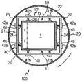
- Figure 2 is a cross-sectional view of the line II-II
- Figure 3 is a preferred embodiment of the present invention
- the electrolyte impregnation enhancing apparatus 100 of a rechargeable battery may include a tray 10 in which a plurality of battery cells 1 may be accommodated, and a tray ( And a vibrating / rotating member 30 capable of vibrating and rotating 10).
- the tray 10 has an accommodating space 12 in which one or more battery cells 1 in which an electrode assembly is embedded may be disposed, and may be disposed in the chamber 20 to be described later.
- the tray 10 has a tray body 11 having a base 14 and a partition 16 and a tray cover 13 which can cover the upper end of the tray body 11.
- the base 14 is formed in a substantially flat plate shape to form the receiving space 12 of the tray 10.
- the partition 16 is for accommodating a plurality of battery cells 1 in a row or a plurality of rows, and is provided substantially perpendicular to the base 14.
- the tray 10 is preferably made of a metal material having excellent thermal conductivity as a whole. However, a portion (not shown) of the storage space 12 of the tray 10 in which the tab or lead portion of each battery cell 1 contacts is formed of a non-metallic material (eg , Reinforced plastics, etc.).
- the battery cell 1 has a structure in which an electrode assembly, a circuit means, and the like are installed therein, and are sealed in a vacuum state after the electrolyte is injected. That is, the electrolyte solution impregnation enhancing apparatus 100 of the secondary battery according to the present embodiment is sealed by the battery cell 1 after the inside of the battery cell 1 is filled with the electrolyte by a separate electrolyte injection facility (not shown) By rotating and vibrating the tray 10 in a state where the respective battery cells 1 are accommodated in the tray 10, the impregnation rate of the electrolyte injected into the battery cell 1 is increased.
- the electrode assembly housed in the battery cell 1 has a structure in which a positive electrode plate, a separator, and a negative electrode plate are sequentially arranged, and at least one positive electrode plate / separator / cathode plate is arranged.
- the positive electrode plate is manufactured by applying a positive electrode active material such as lithium cobalt oxide to the positive electrode current collector in the form of aluminum foil and dried and compressed, and the negative electrode plate is dried by applying a negative electrode active material such as carbon-based active material to the negative electrode current collector in the form of copper foil It is formed by pressing.
- the electrode assembly may be a so-called jelly-roll form in which a roll-shaped cathode plate and a cathode plate are wound in a spiral form with a roll-shaped separator interposed therebetween, respectively, in which stacks of anode plates / separators / cathodes having predetermined specifications are sequentially stacked. It is preferably in the king form. However, it should be understood that the electrode assembly may take any form known in the art.
- the rotation / vibration member 30 may include a chamber 20 in which the tray 10 may be mounted, a vibration member 40 installed in the chamber 20 so as to swing the tray 10 at a predetermined frequency, and a chamber ( And a rotating member 50 capable of rotating the motor 20 at a predetermined rotation speed.
- the chamber 20 includes a case 22 formed in a cylindrical shape, and a plurality of plates 24 installed in the case 22 so as to secure an internal space in which the tray 10 can sufficiently swing. That is, the inner space formed by the plates 24 in the chamber 20 is provided so that the tray 10 is sufficiently spaced apart from the tray 10 so that the tray 10 does not interfere with the tray 10 even if the tray 10 swings by the vibrating member 40. do.
- the case 22 is a skeleton that forms the cylindrical outline of the chamber 20, and the plates 24 are similar to the outline of the tray 10 inside the case 22 but are larger in size.
- the chamber 20 includes a main body 21 having an opening (not shown) that allows the tray 10 to enter and exit, and a cover 23 that can be coupled to the main body 21 to cover the opening.
- the cover 23 is preferably hinged to the main body 21 to selectively open and close the opening of the main body 21.
- one end of the cover 23 and the main body 21 are hinged to each other by the hinge portion 25, the other end of the cover 23 is selectively coupled to the main body 21 by the hook portion 27. .
- the vibrating member 40 is for vibrating the tray 10 located inside the chamber 20 at a predetermined frequency, and includes a plurality of oscillators 42a and 42b provided in the chamber 20. .
- Each of the oscillators 42a and 42b has horizontal oscillators 42a installed on side plates 24a disposed on both sides of the chamber 20, and a bottom disposed on the bottom plate 24b of the chamber 20.
- Vertical oscillators 42b are disposed on the cover plate 24c, which forms the plate 24b and the cover 23 of the chamber 20, respectively.
- the horizontal oscillates 42a and the vertical oscillators 42b are each arranged in at least one pair, and the pair of oscillators 42a and 42b cooperate with each other or operate alone to vibrate the tray 10. Can be driven.
- each of the oscillators 42a and 42b are known in the art, such as a driver for generating a rotational force, a vibration generator driven by the driver to generate vibrations having frequencies out of phase with each other, and a constant frequency generated from the vibration generator. It is provided with a spring to amplify the vibration of the vibration object, that is, the tray 10 to transmit.
- a driver is installed outside the plates 24a, 24b, and 24c of the chamber 20, and a spring is disposed inside the plates 24.
- a contact plate 26 that is in contact with the tray 10 is provided at the end of each spring.
- the contact plate 46 is fitted into a groove (not shown) formed in the outer wall of the tray 10 so that the position of the tray 10 can be stably fixed when the tray 10 is mounted inside the chamber 20. have.
- the vibrating member 40 may include other vibration devices known to be known or known in the future, including a shaker or the like to perform a similar function in addition to the above-described oscillators 42a and 42b. Will understand enough.
- the position where each oscillator 42a or 42b is installed in the chamber 20, the quantity thereof, the operation pattern of such oscillators, etc. can be sufficiently changed by those skilled in the art.
- the oscillators 42a and 42b are described as being arranged in pairs on both sides or on the top and bottom surfaces of the tray 10.
- the left and right sides of the chamber 20 are provided. Either of the oscillators 42a and 42b is fixed to one of the sides, one of the front and rear sides, and one of the upper and lower sides, and the position of the tray 10 is fixed only to the opposite side thereof. Of course, only one may be installed.
- the rotating member 50 is for rotating the tray 10 by rotating the chamber 20 in a state in which the tray 10 is mounted inside the chamber 20, and rotating shafts provided at both ends of the chamber 20 ( 52, a pair of support frames 54 on which the rotation shaft 52 can be supported, and a drive source 56 capable of rotating the rotation shaft 52 at a predetermined rotation speed.
- the drive source 56 has a motor (stepping motor or servo motor) capable of forward and reverse rotation.
- the drive source 56 can be rotated at constant speed but can be adjusted as needed.
- Gears 58 having a predetermined reduction ratio are installed between the drive source 56 and the rotation shaft 52.
- the drive source 25 has a geared motor structure, the drive source may be connected in series with the rotation shaft 52.
- the rotating shaft 52 is supported by the bearing 51 to the support frame.
- FIG. 4 is a partial excerpt cross-sectional view showing another modified example of a tray that can be employed in the electrolyte solution impregnation enhancement device of a secondary battery according to the present invention.
- the same components as the reference numerals described in FIG. 3 are the same members with the same functions.
- the improved tray 10 ′ has a predetermined temperature for the battery cells 1 housed in the tray 10 ′ in order to further increase the impregnation rate of the electrolyte injected into the battery cell 1. It is provided with a heating member 60 to maintain or adjust the range.
- the heating member 60 is in the form of a heating wire or a heating rod provided on the base 14 and the partition 16 of the tray 10 '.
- An insertion groove (not shown) is formed in the base 14 and the partition 16 to install the heating member 60.
- the heating member 60 including the heating wire or the heating rod may be configured such that the tray 10 is separated into two pieces and interposed therebetween.
- the heating member 60 has a material and a structure capable of maintaining a temperature range of about 40 ° C to about 60 ° C or temperature control within that range. Driving and temperature control of the heating member 60 is preferably controlled by a control unit not shown.
- a plurality of battery cells 1 are stored in the tray 10. After the cover 23 of the chamber 20 is opened, the tray 10 is inserted through the opening to seat the tray 10 inside the chamber 20, and then the cover 23 is closed.
- actuating the vibration / rotation member 30 causes the vibration member 40 to drive the oscillators 42a and 42b and each such oscillator 42 horizontally and / or the tray 10. It will swing vertically. Due to the swinging operation, the battery cells 1 accommodated in the tray 10 are rocked and the electrolyte injected into the battery cell 1 may be wetted within the battery cell 1 at a relatively higher speed. .
- the rotating member 50 which can be driven simultaneously or selectively with the operation of the above-mentioned vibration member 40.
- the driving source 56 is driven to rotate the rotating shaft 52 at a predetermined speed, thereby rotating the chamber 20 so that the tray 10 disposed inside the chamber 20 is horizontally disposed ( 52) to rotate.
- the rotation of the chamber 20 may be an intermittent rotation as well as a continuous rotation, or may not be a 360 degree rotation.
- the battery cells 1 accommodated in the tray 10 are vibrated by the vibrating member 40 even while the rotating operation of the chamber 20 by the rotating member 50 is continued.
- the rotation of the chamber 20 by the rotating member 50, and consequently the rotation of the tray 10, is independent of the influence of its own weight or the vibrating motion of the vibrating member 40. It is possible to increase the impregnation rate of the injected electrolyte.
- the rotation / vibration member 30 is stopped. Then, the cover 23 of the chamber 20 is opened to separate the tray 10 from the chamber 20 through the opening. This process may be included in the aging process of the battery cell 1 or may be performed before. The battery cell 1 which has undergone the aging process is subjected to a process such as a final fusion operation.
- FIG. 5 is a cross-sectional view schematically illustrating a configuration of an electrolyte solution impregnation enhancing apparatus of a secondary battery according to a second exemplary embodiment of the present invention.
- the same components as those described in FIGS. 1 to 3 are the same members with the same functions.
- the electrolyte solution impregnation enhancing apparatus 200 configures the shape of the chamber 120 for accommodating the tray 10 into a non-cylindrical cuboid type of the above-described embodiment, and forms the chamber 120 of the rectangular parallelepiped type. It is configured to rotate using the rotating member 150 provided on the lower side.
- the chamber 120 includes a substantially rectangular parallelepiped main body 121 that can accommodate the tray 10 so as to secure a sufficient swing space of the tray 10, and has an open top.
- the main body 121 includes a structure in which a plurality of panels or plates are connected to each other, an upper portion of which is open to form an open end, and through which the tray 10 may enter and exit.
- the rotation member 150 includes a rotation shaft 152 installed on the bottom surface of the chamber 120 and a driving source 56 installed on the horizontal frame 153 so as to rotate the rotation shaft 152. That is, the rotation shaft 152 is installed to be rotatable by a bearing (not shown) between the bottom surface 124 of the chamber 120 and the horizontal plate 153.
- the horizontal oscillates 46a are installed on both sides 122 of the chamber 120, but the vertical oscillates 46b are formed in the chamber 140. It is installed only on the bottom surface 124.
- the tray 10 is accommodated in an open state in the rectangular parallelepiped chamber 120, and the rotating member 150 rotates the chamber 120 in the horizontal direction at the bottom of the chamber 120.
- the tray 10 mounted inside the 120 rotates horizontally, and the pre-cells 1 accommodated in the tray 10 also rotate in the horizontal direction while being vibrated by the vibrating member 40 at the same time.
- the impregnation rate of the electrolyte solution injected therein can be increased.
- the operation of the apparatus 200 according to the present embodiment is similar to that of the first embodiment described above, except that the chamber 140 is rotated on a horizontal plane by the horizontal rotation of the rotating member 150. It differs from an Example.
- the electrolyte impregnation enhancing apparatus may be integrated into one structure without distinguishing the vibration member and the rotating member constituting the vibration / rotation member.
- the chamber rotates and vibrates in the rotation / vibration shaft.
- the rotation / vibration shaft can be formed into a double-axis structure that can be stretched inside the shaft while actually rotating.
Landscapes
- Chemical & Material Sciences (AREA)
- Chemical Kinetics & Catalysis (AREA)
- Electrochemistry (AREA)
- General Chemical & Material Sciences (AREA)
- Engineering & Computer Science (AREA)
- Manufacturing & Machinery (AREA)
- Filling, Topping-Up Batteries (AREA)
- Secondary Cells (AREA)
Abstract
La présente invention concerne un dispositif permettant l'amélioration d'imprégnation électrolytique pour une batterie rechargeable, le dispositif comportant: un plateau dans lequel une ou des cellules de batterie est/sont stockée(s); et un organe de vibration/rotation qui soumet le plateau à une secousse et une rotation simultanées.
Priority Applications (5)
| Application Number | Priority Date | Filing Date | Title |
|---|---|---|---|
| CN201180000706.2A CN102612767B (zh) | 2010-09-30 | 2011-03-23 | 用于增强二次电池中的电解质的浸渍的装置和方法 |
| PL11730169T PL2618404T3 (pl) | 2010-09-30 | 2011-03-23 | Urządzenie i sposób do poprawy impregnacji elektrolitem w baterii akumulatorowej |
| JP2012536721A JP5406378B2 (ja) | 2010-09-30 | 2011-03-23 | 二次電池の電解液含浸増進装置及び方法 |
| EP11730169.7A EP2618404B1 (fr) | 2010-09-30 | 2011-03-23 | Dispositif et procédé pour améliorer l'imprégnation électrolytique pour batterie rechargeable |
| US13/670,041 US8728650B2 (en) | 2010-09-30 | 2012-11-06 | Apparatus and method for enhancing impregnation with electrolyte in secondary battery |
Applications Claiming Priority (2)
| Application Number | Priority Date | Filing Date | Title |
|---|---|---|---|
| KR1020100095277A KR101300591B1 (ko) | 2010-09-30 | 2010-09-30 | 이차 전지의 전해액 함침 증진 장치 및 방법 |
| KR10-2010-0095277 | 2010-09-30 |
Related Child Applications (1)
| Application Number | Title | Priority Date | Filing Date |
|---|---|---|---|
| US13/670,041 Continuation US8728650B2 (en) | 2010-09-30 | 2012-11-06 | Apparatus and method for enhancing impregnation with electrolyte in secondary battery |
Publications (1)
| Publication Number | Publication Date |
|---|---|
| WO2012043948A1 true WO2012043948A1 (fr) | 2012-04-05 |
Family
ID=45893363
Family Applications (1)
| Application Number | Title | Priority Date | Filing Date |
|---|---|---|---|
| PCT/KR2011/001996 Ceased WO2012043948A1 (fr) | 2010-09-30 | 2011-03-23 | Dispositif et procédé pour améliorer l'imprégnation électrolytique pour batterie rechargeable |
Country Status (7)
| Country | Link |
|---|---|
| US (1) | US8728650B2 (fr) |
| EP (1) | EP2618404B1 (fr) |
| JP (1) | JP5406378B2 (fr) |
| KR (1) | KR101300591B1 (fr) |
| CN (2) | CN104701485B (fr) |
| PL (1) | PL2618404T3 (fr) |
| WO (1) | WO2012043948A1 (fr) |
Families Citing this family (26)
| Publication number | Priority date | Publication date | Assignee | Title |
|---|---|---|---|---|
| CN104584305A (zh) * | 2012-11-08 | 2015-04-29 | 株式会社Lg化学 | 制造二次电池的方法 |
| CN104584306A (zh) * | 2012-11-08 | 2015-04-29 | 株式会社Lg化学 | 二次电池的制造方法 |
| KR20160068929A (ko) * | 2013-10-15 | 2016-06-15 | 도요타지도샤가부시키가이샤 | 이차 전지의 제조 방법 |
| JP6260297B2 (ja) * | 2014-01-23 | 2018-01-17 | 株式会社豊田自動織機 | 恒温装置、及び蓄電装置の製造方法 |
| KR101942443B1 (ko) * | 2015-06-25 | 2019-01-25 | 주식회사 엘지화학 | 이차 전지 제조 방법 및 이차 전지의 젖음 공정 장치 |
| KR101942496B1 (ko) * | 2015-08-20 | 2019-01-25 | 주식회사 엘지화학 | 진동을 이용한 전지셀 제조용 가스 트랩 제거 장치 |
| KR101998585B1 (ko) * | 2015-09-02 | 2019-07-10 | 주식회사 엘지화학 | 함침의 향상을 위해 진동을 이용하는 전지셀 제조용 전해액 함침 장치 |
| KR102552926B1 (ko) * | 2015-10-30 | 2023-07-10 | 삼성에스디아이 주식회사 | 이차전지의 전해액 함습 촉진 장치 및 이를 이용한 전해액 함습 촉진 방법 |
| KR102114263B1 (ko) * | 2016-01-22 | 2020-05-22 | 주식회사 엘지화학 | 함침의 향상을 위해 물리적 자극을 이용하는 전지셀 제조용 전해액 함침 장치 |
| KR101953349B1 (ko) * | 2016-02-22 | 2019-02-28 | 주식회사 엘지화학 | 에어로겔 시트용 제조장치 |
| WO2017171446A1 (fr) * | 2016-03-30 | 2017-10-05 | 주식회사 엘지화학 | Procédé de production de batterie secondaire au lithium |
| JP6689512B2 (ja) * | 2016-03-30 | 2020-04-28 | エルジー・ケム・リミテッド | リチウム二次電池の製造方法 |
| KR101949973B1 (ko) | 2016-04-15 | 2019-02-20 | 주식회사 엘지화학 | 전해액 함침장치 |
| KR102110808B1 (ko) * | 2016-05-31 | 2020-05-14 | 주식회사 엘지화학 | 이차전지용 전해액 함침 시스템 및 이를 이용하는 전해액 함침 방법 |
| US10431791B2 (en) * | 2016-11-01 | 2019-10-01 | Ford Global Technologies, Llc | Traction battery pack shield and shielding method |
| DE102016225173A1 (de) * | 2016-12-15 | 2018-06-21 | Robert Bosch Gmbh | Verfahren und System zur Herstellung einer Batteriezelle |
| DE102017206315A1 (de) * | 2017-04-12 | 2018-10-18 | Ford Global Technologies, Llc | Imprägnierverfahren |
| KR102728026B1 (ko) * | 2018-10-16 | 2024-11-07 | 주식회사 엘지에너지솔루션 | 이차전지 셀 에이징 장치 및 에이징 방법 |
| KR102548344B1 (ko) * | 2019-03-18 | 2023-06-26 | 주식회사 엘지에너지솔루션 | 진동을 이용하는 전지셀 제조용 전해액 함침 장치 및 이를 이용하는 전지셀 제조방법 |
| CN112742658B (zh) * | 2021-02-03 | 2022-03-25 | 宝丰县五星石墨有限公司 | 一种石墨制品电极浸渍装置 |
| CN113113739B (zh) * | 2021-02-23 | 2023-06-13 | 惠州市恒泰科技股份有限公司 | 高电压锂离子电池、电池极片及其浸润方法 |
| CN113212204A (zh) * | 2021-05-13 | 2021-08-06 | 武汉蔚能电池资产有限公司 | 用于提升电池快充性能的外加旋转充电散热装置 |
| EP4254578B1 (fr) * | 2021-06-09 | 2026-04-29 | LG Energy Solution, Ltd. | Dispositif d'imprégnation d'électrolyte |
| JP7600928B2 (ja) * | 2021-08-10 | 2024-12-17 | トヨタ自動車株式会社 | 電池の製造方法 |
| US12149192B2 (en) * | 2022-03-07 | 2024-11-19 | Wavetech Gmbh | Method and device for restoration of a battery's energy parameters |
| KR20250179088A (ko) * | 2024-06-20 | 2025-12-29 | 주식회사 엘지에너지솔루션 | 전지 셀의 보관용 랙 및 이를 포함하는 전지 셀 보관 장치 |
Citations (4)
| Publication number | Priority date | Publication date | Assignee | Title |
|---|---|---|---|---|
| JPH07326338A (ja) * | 1994-05-30 | 1995-12-12 | Sanyo Electric Co Ltd | 電池の製造方法 |
| KR960027023A (ko) * | 1994-12-28 | 1996-07-22 | 윤종용 | 알칼리 전지의 전해액 주입 방법 및 장치 |
| JPH08273659A (ja) * | 1995-04-03 | 1996-10-18 | Toshiba Corp | 電解液含浸方法およびその装置 |
| JPH11265705A (ja) * | 1998-03-16 | 1999-09-28 | Mitsubishi Cable Ind Ltd | 電池の製造方法及びその装置 |
Family Cites Families (9)
| Publication number | Priority date | Publication date | Assignee | Title |
|---|---|---|---|---|
| US2996038A (en) * | 1952-10-20 | 1961-08-15 | Sprague Electric Co | Apparatus for impregnating electrolytic capacitors |
| JP2643536B2 (ja) | 1990-05-24 | 1997-08-20 | 富士写真フイルム株式会社 | 溶融型熱転写記録方法 |
| JP2975701B2 (ja) * | 1991-03-11 | 1999-11-10 | 三洋電機株式会社 | 金属水素化物蓄電池の製造方法 |
| JPH05190168A (ja) * | 1992-01-10 | 1993-07-30 | Toshiba Corp | 電解液真空注液方法およびそれに用いる装置 |
| US6006439A (en) * | 1998-05-20 | 1999-12-28 | Acumuladores Mexicanos, S.A. De C.V. | Apparatus for cleaning and drying a plurality of plate lug surfaces for producing pore-free cast-on-strap joints for lead-acid batteries |
| JP2000114124A (ja) * | 1998-10-07 | 2000-04-21 | Jcc Engineering Kk | 電解コンデンサ素子の電解液真空含浸方法及び装置 |
| JP2000340215A (ja) * | 1999-05-26 | 2000-12-08 | Sony Corp | 電池製造における電解液注入方法及び電解液注入装置 |
| JP2001210310A (ja) * | 2000-01-25 | 2001-08-03 | Sony Corp | 電解液含浸方法及び電解液含浸装置 |
| CN100568607C (zh) * | 2005-12-22 | 2009-12-09 | 比亚迪股份有限公司 | 电池动态陈化方法及其动态陈化装置 |
-
2010
- 2010-09-30 KR KR1020100095277A patent/KR101300591B1/ko active Active
-
2011
- 2011-03-23 CN CN201510141506.9A patent/CN104701485B/zh active Active
- 2011-03-23 PL PL11730169T patent/PL2618404T3/pl unknown
- 2011-03-23 CN CN201180000706.2A patent/CN102612767B/zh active Active
- 2011-03-23 JP JP2012536721A patent/JP5406378B2/ja active Active
- 2011-03-23 WO PCT/KR2011/001996 patent/WO2012043948A1/fr not_active Ceased
- 2011-03-23 EP EP11730169.7A patent/EP2618404B1/fr active Active
-
2012
- 2012-11-06 US US13/670,041 patent/US8728650B2/en active Active
Patent Citations (4)
| Publication number | Priority date | Publication date | Assignee | Title |
|---|---|---|---|---|
| JPH07326338A (ja) * | 1994-05-30 | 1995-12-12 | Sanyo Electric Co Ltd | 電池の製造方法 |
| KR960027023A (ko) * | 1994-12-28 | 1996-07-22 | 윤종용 | 알칼리 전지의 전해액 주입 방법 및 장치 |
| JPH08273659A (ja) * | 1995-04-03 | 1996-10-18 | Toshiba Corp | 電解液含浸方法およびその装置 |
| JPH11265705A (ja) * | 1998-03-16 | 1999-09-28 | Mitsubishi Cable Ind Ltd | 電池の製造方法及びその装置 |
Non-Patent Citations (1)
| Title |
|---|
| See also references of EP2618404A4 * |
Also Published As
| Publication number | Publication date |
|---|---|
| EP2618404A4 (fr) | 2016-12-21 |
| CN104701485B (zh) | 2017-08-15 |
| US20130065111A1 (en) | 2013-03-14 |
| JP5406378B2 (ja) | 2014-02-05 |
| KR101300591B1 (ko) | 2013-08-27 |
| JP2012533166A (ja) | 2012-12-20 |
| CN104701485A (zh) | 2015-06-10 |
| CN102612767B (zh) | 2015-08-12 |
| EP2618404A1 (fr) | 2013-07-24 |
| KR20120033647A (ko) | 2012-04-09 |
| PL2618404T3 (pl) | 2019-10-31 |
| US8728650B2 (en) | 2014-05-20 |
| CN102612767A (zh) | 2012-07-25 |
| EP2618404B1 (fr) | 2019-05-01 |
Similar Documents
| Publication | Publication Date | Title |
|---|---|---|
| WO2012043948A1 (fr) | Dispositif et procédé pour améliorer l'imprégnation électrolytique pour batterie rechargeable | |
| JP6496454B2 (ja) | バッテリーモジュール、該バッテリーモジュールを含むバッテリーパック及び該バッテリーパックを含む自動車 | |
| US5378551A (en) | Rechargeable battery cell having integral vibrating means | |
| WO2018174414A1 (fr) | Module de batterie, bloc-batterie comprenant le module de batterie, et véhicule automobile comprenant un bloc-batterie | |
| WO2017095003A1 (fr) | Module de batterie comprenant une cartouche comportant des parties de préhension | |
| KR102455471B1 (ko) | 배터리 셀, 이를 포함하는 배터리 모듈, 배터리 랙 및 전력 저장 장치 | |
| WO2020067659A1 (fr) | Module de batterie, bloc-batterie comprenant un module de batterie, et véhicule comprenant un bloc-batterie | |
| KR20120010414A (ko) | 전극의 프리 도핑 시스템 및 이를 이용한 전극의 프리 도핑 방법 | |
| JP4449485B2 (ja) | バイポーラ電池、組電池およびこれらの電池を備えた車両 | |
| JP2012146681A (ja) | 電気デバイス集合体 | |
| CN111801831A (zh) | 包括磁体的按压夹具和包括该按压夹具的电池模块 | |
| WO2020189962A1 (fr) | Dispositif de mouillage d'électrolyte destiné à la fabrication d'un élément de batterie au moyen d'une vibration et procédé de fabrication d'élément de batterie utilisant ce dernier | |
| KR20140085454A (ko) | 용융염 전지 장치 및 용융염 전지 장치의 제어 방법 | |
| WO2018186597A1 (fr) | Procédé de fabrication d'une batterie secondaire au lithium | |
| WO2017030272A1 (fr) | Appareil d'élimination de piège à gaz destiné à la fabrication d'un élément de batterie à l'aide de vibrations | |
| CN210403873U (zh) | 电池模块、电池组及装置 | |
| JP7570503B2 (ja) | バッテリーパック、電源システム及び自動車 | |
| CN220774554U (zh) | 电池盖板、电池单体、电池和用电设备 | |
| US20240014532A1 (en) | Battery cell fixing device and electrolyte impregnation device including the same | |
| CN113871811A (zh) | 用于锂电池加工的电芯浸润装置 | |
| CN215695932U (zh) | 一种电池包充电功能检测装置 | |
| KR20170004217A (ko) | 이차전지의 제작 방법 | |
| KR20250120016A (ko) | 전해액 함침장치 및 배터리셀 제조방법 | |
| CN220984594U (zh) | 固态电芯结构、电池包及用电设备 | |
| CN220253380U (zh) | 电池单体、电池及用电装置 |
Legal Events
| Date | Code | Title | Description |
|---|---|---|---|
| WWE | Wipo information: entry into national phase |
Ref document number: 201180000706.2 Country of ref document: CN |
|
| WWE | Wipo information: entry into national phase |
Ref document number: 2012536721 Country of ref document: JP |
|
| WWE | Wipo information: entry into national phase |
Ref document number: 2011730169 Country of ref document: EP |
|
| 121 | Ep: the epo has been informed by wipo that ep was designated in this application |
Ref document number: 11730169 Country of ref document: EP Kind code of ref document: A1 |
|
| NENP | Non-entry into the national phase |
Ref country code: DE |