WO2012050000A1 - 空気入りタイヤ - Google Patents
空気入りタイヤ Download PDFInfo
- Publication number
- WO2012050000A1 WO2012050000A1 PCT/JP2011/072778 JP2011072778W WO2012050000A1 WO 2012050000 A1 WO2012050000 A1 WO 2012050000A1 JP 2011072778 W JP2011072778 W JP 2011072778W WO 2012050000 A1 WO2012050000 A1 WO 2012050000A1
- Authority
- WO
- WIPO (PCT)
- Prior art keywords
- tire
- axial direction
- tread
- band
- width
- Prior art date
- Legal status (The legal status is an assumption and is not a legal conclusion. Google has not performed a legal analysis and makes no representation as to the accuracy of the status listed.)
- Ceased
Links
Images


Classifications
-
- B—PERFORMING OPERATIONS; TRANSPORTING
- B60—VEHICLES IN GENERAL
- B60C—VEHICLE TYRES; TYRE INFLATION; TYRE CHANGING; CONNECTING VALVES TO INFLATABLE ELASTIC BODIES IN GENERAL; DEVICES OR ARRANGEMENTS RELATED TO TYRES
- B60C5/00—Inflatable pneumatic tyres or inner tubes
- B60C5/02—Inflatable pneumatic tyres or inner tubes having separate inflatable inserts, e.g. with inner tubes; Means for lubricating, venting, preventing relative movement between tyre and inner tube
- B60C5/04—Shape or construction of inflatable inserts
-
- B—PERFORMING OPERATIONS; TRANSPORTING
- B60—VEHICLES IN GENERAL
- B60C—VEHICLE TYRES; TYRE INFLATION; TYRE CHANGING; CONNECTING VALVES TO INFLATABLE ELASTIC BODIES IN GENERAL; DEVICES OR ARRANGEMENTS RELATED TO TYRES
- B60C9/00—Reinforcements or ply arrangement of pneumatic tyres
- B60C9/18—Structure or arrangement of belts or breakers, crown-reinforcing or cushioning layers
- B60C9/20—Structure or arrangement of belts or breakers, crown-reinforcing or cushioning layers built-up from rubberised plies each having all cords arranged substantially parallel
- B60C9/22—Structure or arrangement of belts or breakers, crown-reinforcing or cushioning layers built-up from rubberised plies each having all cords arranged substantially parallel the plies being arranged with all cords disposed along the circumference of the tyre
- B60C9/2204—Structure or arrangement of belts or breakers, crown-reinforcing or cushioning layers built-up from rubberised plies each having all cords arranged substantially parallel the plies being arranged with all cords disposed along the circumference of the tyre obtained by circumferentially narrow strip winding
-
- B—PERFORMING OPERATIONS; TRANSPORTING
- B60—VEHICLES IN GENERAL
- B60C—VEHICLE TYRES; TYRE INFLATION; TYRE CHANGING; CONNECTING VALVES TO INFLATABLE ELASTIC BODIES IN GENERAL; DEVICES OR ARRANGEMENTS RELATED TO TYRES
- B60C19/00—Tyre parts or constructions not otherwise provided for
- B60C19/002—Noise damping elements provided in the tyre structure or attached thereto, e.g. in the tyre interior
-
- B—PERFORMING OPERATIONS; TRANSPORTING
- B60—VEHICLES IN GENERAL
- B60C—VEHICLE TYRES; TYRE INFLATION; TYRE CHANGING; CONNECTING VALVES TO INFLATABLE ELASTIC BODIES IN GENERAL; DEVICES OR ARRANGEMENTS RELATED TO TYRES
- B60C5/00—Inflatable pneumatic tyres or inner tubes
- B60C5/02—Inflatable pneumatic tyres or inner tubes having separate inflatable inserts, e.g. with inner tubes; Means for lubricating, venting, preventing relative movement between tyre and inner tube
- B60C5/04—Shape or construction of inflatable inserts
- B60C5/08—Shape or construction of inflatable inserts having reinforcing means
-
- B—PERFORMING OPERATIONS; TRANSPORTING
- B60—VEHICLES IN GENERAL
- B60C—VEHICLE TYRES; TYRE INFLATION; TYRE CHANGING; CONNECTING VALVES TO INFLATABLE ELASTIC BODIES IN GENERAL; DEVICES OR ARRANGEMENTS RELATED TO TYRES
- B60C9/00—Reinforcements or ply arrangement of pneumatic tyres
- B60C9/18—Structure or arrangement of belts or breakers, crown-reinforcing or cushioning layers
-
- B—PERFORMING OPERATIONS; TRANSPORTING
- B60—VEHICLES IN GENERAL
- B60C—VEHICLE TYRES; TYRE INFLATION; TYRE CHANGING; CONNECTING VALVES TO INFLATABLE ELASTIC BODIES IN GENERAL; DEVICES OR ARRANGEMENTS RELATED TO TYRES
- B60C9/00—Reinforcements or ply arrangement of pneumatic tyres
- B60C9/18—Structure or arrangement of belts or breakers, crown-reinforcing or cushioning layers
- B60C9/20—Structure or arrangement of belts or breakers, crown-reinforcing or cushioning layers built-up from rubberised plies each having all cords arranged substantially parallel
- B60C9/22—Structure or arrangement of belts or breakers, crown-reinforcing or cushioning layers built-up from rubberised plies each having all cords arranged substantially parallel the plies being arranged with all cords disposed along the circumference of the tyre
-
- B—PERFORMING OPERATIONS; TRANSPORTING
- B60—VEHICLES IN GENERAL
- B60C—VEHICLE TYRES; TYRE INFLATION; TYRE CHANGING; CONNECTING VALVES TO INFLATABLE ELASTIC BODIES IN GENERAL; DEVICES OR ARRANGEMENTS RELATED TO TYRES
- B60C9/00—Reinforcements or ply arrangement of pneumatic tyres
- B60C9/18—Structure or arrangement of belts or breakers, crown-reinforcing or cushioning layers
- B60C9/20—Structure or arrangement of belts or breakers, crown-reinforcing or cushioning layers built-up from rubberised plies each having all cords arranged substantially parallel
- B60C9/22—Structure or arrangement of belts or breakers, crown-reinforcing or cushioning layers built-up from rubberised plies each having all cords arranged substantially parallel the plies being arranged with all cords disposed along the circumference of the tyre
- B60C2009/2219—Structure or arrangement of belts or breakers, crown-reinforcing or cushioning layers built-up from rubberised plies each having all cords arranged substantially parallel the plies being arranged with all cords disposed along the circumference of the tyre with a partial zero degree ply at the belt edges - edge band
-
- B—PERFORMING OPERATIONS; TRANSPORTING
- B60—VEHICLES IN GENERAL
- B60C—VEHICLE TYRES; TYRE INFLATION; TYRE CHANGING; CONNECTING VALVES TO INFLATABLE ELASTIC BODIES IN GENERAL; DEVICES OR ARRANGEMENTS RELATED TO TYRES
- B60C9/00—Reinforcements or ply arrangement of pneumatic tyres
- B60C9/18—Structure or arrangement of belts or breakers, crown-reinforcing or cushioning layers
- B60C9/28—Structure or arrangement of belts or breakers, crown-reinforcing or cushioning layers characterised by the belt or breaker dimensions or curvature relative to carcass
-
- Y—GENERAL TAGGING OF NEW TECHNOLOGICAL DEVELOPMENTS; GENERAL TAGGING OF CROSS-SECTIONAL TECHNOLOGIES SPANNING OVER SEVERAL SECTIONS OF THE IPC; TECHNICAL SUBJECTS COVERED BY FORMER USPC CROSS-REFERENCE ART COLLECTIONS [XRACs] AND DIGESTS
- Y10—TECHNICAL SUBJECTS COVERED BY FORMER USPC
- Y10T—TECHNICAL SUBJECTS COVERED BY FORMER US CLASSIFICATION
- Y10T152/00—Resilient tires and wheels
- Y10T152/10—Tires, resilient
- Y10T152/10495—Pneumatic tire or inner tube
- Y10T152/10765—Characterized by belt or breaker structure
Definitions
- the present invention relates to a pneumatic tire that comprehensively improves shoulder wear, noise outside the vehicle, and high-speed durability.
- FIG. 5 shows a band layer A that covers the belt layer B over its entire width.
- the band layer A can suppress lifting (lifting) of the belt layer B due to centrifugal force during high-speed running, particularly lifting at the outer end B1 which is a free end. Therefore, such a pneumatic tire can reduce distortion and heat generation in the tread shoulder portion Ys and improve high-speed durability.
- the restraining force is enhanced to improve the vibration characteristics, and the outside noise such as pattern noise is also reduced. It has been broken.
- the present invention provides a covering width of the belt layer outer end by an overlapping portion where two band plies overlap each other, a width of the sound damper, and an inner end in the tire axial direction of the overlapping portion and an outer end in the tire axial direction of the damper. Based on the regulation of the distance of the air, the combination of the sound control body and the band layer suppresses the deterioration of shoulder wear, noise outside the vehicle, or high-speed durability, and can improve these comprehensively.
- the purpose is to provide tires.
- the present invention provides a carcass from the tread portion to the bead core of the bead portion through the sidewall portion, A belt layer disposed radially outside of the carcass and inside the tread portion; A band layer disposed radially outward of the belt layer; A pneumatic tire comprising a band-shaped sound absorber made of a sponge material attached to a radially inner surface of the tread portion and extending in a tire circumferential direction, The sound damping body has a width WA in the tire axial direction of 40 to 70% of the tread ground contact width TW.
- the band layer is composed of two band plies in which organic fiber band cords are spirally wound at an angle of 10 degrees or less with respect to the tire circumferential direction, and the two band plies are radially inner and outer.
- the overlapping portion covers the outer end portion in the tire axial direction of the belt layer with a covering width WB of 10 to 25% of the tread ground contact width TW,
- the outer end in the tire axial direction of the overlapping portion is located at the same position as the outer end F in the tire axial direction of the belt layer or on the outer side in the tire axial direction, and the inner end in the tire axial direction of the overlapping portion is The distance LC is separated from the outer end E of the sound body in the tire axial direction to the outer side in the tire axial direction, and the distance LC is 5 to 20% of the tread contact width TW.
- the covering width WB on the outer end portion of the belt layer by the overlapping portion where the two band plies overlap is wider.
- the width WA of the noise suppressor is wide.
- the covering width WB is widened and / or the width WA of the sound damping body is widened
- the overlapping portion and the sound damping body overlap in the radial direction inside or outside, or the overlapping portion of the tire axial direction inner end and the sound damping are overlapped.
- the distance LC with the outer end in the tire axial direction of the body is small.
- the overlapping portion and the sound damping body overlap each other in the radial direction, or when the distance LC between the inner end of the overlapping portion and the outer end of the sound suppressing body is too small. It has been found that due to the heat storage effect of the noise control body, damage tends to occur starting from the inner end of the overlapping portion, and high-speed durability is reduced.
- the covering width WB and / or the width WA of the noise damper it is necessary to reduce the covering width WB and / or the width WA of the noise damper.
- the covering width WB is made too small, the restraining force of the band layer is reduced, leading to a decrease in outside noise performance and high-speed durability.
- the region width between the overlapping portions is increased and the tread crown portion is easily expanded, the contact pressure of the tread shoulder portion with respect to the tread crown portion is relatively reduced. As a result, the tread shoulder portion becomes slippery with respect to the road surface during traveling, and shoulder wear is likely to occur.
- the width WA of the noise control body is too small, the effect of suppressing the air column resonance by the noise control body is not exhibited.
- the covering width WB and the width of the sound control body WA are dared to be the minimum values, respectively, and the distance LC between the inner end of the overlapping portion and the outer end of the sound control body is secured. is doing. Therefore, it is possible to comprehensively improve shoulder wear, vehicle exterior noise, and high-speed durability in a well-balanced manner while suppressing in-vehicle noise such as road noise.
- the belt layer is composed of two belt plies in which steel cords are inclined and arranged at an angle of 20 to 30 degrees with respect to the tire circumferential direction, and the belt plies have different belt cord inclination directions from each other. It is desirable to be placed in piles.
- FIG. 1 is a meridional sectional view of an example of a pneumatic tire according to the present invention.
- 1 is a circumferential cross-sectional view along a tire equator of an embodiment of a pneumatic tire. It is a partial expanded sectional view which expands and shows a part of pneumatic tire.
- FIG. 2 is a cross-sectional view of a sound control body used in Table 1. It is meridional sectional drawing which shows an example of the conventional tire.
- a pneumatic tire 1 includes a carcass 6 that extends from a tread portion 2 through a sidewall portion 3 to a bead core 5 of a bead portion 4, a radially outer side of the carcass 6, and the tread portion 2.
- a belt layer 7 comprising a belt layer 7 disposed inside, a band layer 9 disposed further outward in the radial direction of the belt layer 7, and a sponge material attached to the radial inner surface TS of the tread portion 2 and extending in the tire circumferential direction.
- the noise control body 10 at least the noise control body 10.
- the carcass 6 is composed of one or more carcass plies 6A in this example, in which carcass cords are arranged at an angle of, for example, 75 ° to 90 ° with respect to the tire circumferential direction.
- the carcass ply 6 ⁇ / b> A includes a series of ply folding portions 6 b that are folded from the inside to the outside around the bead core 5 at both ends of the ply body portion 6 a that extends between the bead cores 5 and 5.
- a bead apex rubber 8 for bead reinforcement that extends from the bead core 5 to the outer side in the tire radial direction is disposed between the ply main body portion 6a and the folded portion 6b.
- a polyester cord is employed in this example, but other than this, an organic fiber cord such as nylon, rayon, aramid, or a steel cord may be employed if necessary.
- the belt layer 7 is formed of two belt plies 7A and 7B in which belt cords, which are steel cords, are inclined and arranged at an angle of 20 to 30 degrees with respect to the tire circumferential direction.
- the belt plies 7A and 7B are placed with the belt cords inclined in different directions.
- the belt cords cross each other between the plies, increase the belt rigidity, and reinforce the substantially entire width of the tread portion 2.
- the belt ply 7A on the inner side in the tire radial direction is formed slightly wider than the outer belt ply 7B.
- the band layer 9 includes two bands in which an organic fiber band cord, in this example, a nylon cord, is spirally wound at an angle of 10 degrees or less, preferably 5 degrees or less with respect to the tire circumferential direction.
- the plies 9A and 9B are formed.
- the band layer 9 includes an overlapping portion 12 in which the two band plies 9A and 9B overlap in the radial direction inside and outside to form two layers.
- the radially inner band ply 9 ⁇ / b> A is formed as a so-called full band ply 13 that is placed over the belt layer 7 over its entire width.
- the band ply 9B on the outer side in the radial direction is formed as a so-called edge band ply 14 which is placed only on the outer end portion in the tire axial direction of the belt layer 7 is illustrated.
- the inner band ply 9A may be the edge band ply 14 and the outer band ply 9B may be the full band ply 13, or both the band plies 9A and 9B may be formed of the edge band ply 14. good.
- the overlapping portion 12 covers the outer end portion in the tire axial direction of the belt layer 7 with a covering width WB of 10 to 20% of the tread ground contact width TW.
- the tire axial direction outer end 12o of the overlapping portion 12 is provided at the same position as the tire axial direction outer end F of the belt layer 7 or on the outer side in the tire axial direction. Further, the inner end 12i in the tire axial direction of the overlapping portion 12 is provided at a distance LC from the outer end E in the tire axial direction of the sound damper 10 toward the outer side in the tire axial direction.
- the sound control body 10 is made of a sponge material.
- the sponge material is a sponge-like porous structure, for example, a web in which animal fibers, plant fibers, or synthetic fibers are entangled and integrally connected in addition to a so-called sponge having open cells in which rubber or synthetic resin is foamed. It shall be included.
- the “porous structure” includes not only open cells but also closed cells.
- an open-cell sponge material made of polyurethane is used for the sound damper 10 of this example.
- the sponge material as described above reduces the sound (air column resonance energy) and reduces the road noise by converting the vibration energy of the air that vibrates the surface or the internal porous portion into heat energy and consuming it.
- the sponge material since the sponge material is easily deformed such as contraction and bending, it does not substantially affect the deformation of the tire during running. For this reason, it can prevent that steering stability deteriorates.
- the specific gravity of the sponge material is very small, it is possible to prevent deterioration of the weight balance of the tire.
- the sponge material is preferably an ether polyurethane sponge, ester polyurethane sponge, synthetic resin sponge such as polyethylene sponge, chloroprene rubber sponge (CR sponge), ethylene propylene rubber sponge (EDPM sponge), nitrile rubber sponge (NBR sponge), etc.
- a rubber sponge can be suitably used, and a polyurethane or polyethylene-based sponge including an ether polyurethane sponge is particularly preferable from the viewpoints of sound damping properties, light weight, foaming controllability, durability, and the like.
- the noise control body 10 has a long belt shape having a bottom surface 10A fixed to the radially inner surface TS of the tread portion 2, and extends in the tire circumferential direction as shown in FIG.
- the sound damping body 10 can be formed in a substantially annular shape by the outer end portions 10e and 10e in the circumferential direction being in contact with each other, and the outer end portions 10e and 10e are separated in the circumferential direction as shown in FIG. Also good.
- the outer end portion 10e is formed as a tapered portion 20 whose thickness (height) gradually decreases toward the end in the tire circumferential direction. It is preferable in preventing crack damage.
- the sound damper 10 has substantially the same cross-sectional shape at each position in the circumferential direction except the outer end portion 10e.
- the cross-sectional shape a flat and oblong shape having a height H smaller than the width WA in the tire axial direction is preferable in order to prevent the vehicle from falling or deforming.
- the sound damper 10 is preferably provided with a concave groove 21 extending continuously in the circumferential direction on the radially inner surface 10B side as in the present embodiment.
- the concave groove 21 can increase the surface area of the sound control body 10 and absorb more resonance energy, and can improve heat dissipation and suppress the temperature rise of the sponge material.
- the width WA in the tire axial direction of the sound damper 10 is 40 to 70% of the tread ground contact width TW, and the covering width WB on the belt layer 7 by the overlapping portion 12 is 10 to 25% of the tread ground contact width TW.
- the tire axial distance LC between the tire axial inner end 12i of the overlapping portion 12 and the tire axial outer end E of the sound damper 10 is set to 5 to 20% of the tread ground contact width TW.
- the tread contact width TW is defined as the width in the tire axial direction of the tread contact surface that can be contacted when a normal load is applied to a tire that is assembled to a normal rim and filled with a normal internal pressure.
- the “regular rim” is a rim determined for each tire in the standard system including the standard on which the tire is based, for example, a standard rim for JATMA, and “Design Rim” for TRA, or For ETRTO, it means “Measuring” Rim.
- the “regular internal pressure” is the air pressure determined by the standard for each tire.
- the maximum air pressure for JATMA the maximum value for ETRA, Means “INFLATION PRESSURE”, but in the case of a passenger car tire, it is 180 kPa.
- the "regular load” is the load specified by the standard for each tire. If it is JATMA, it is the maximum load capacity. If it is ETRTO, it will be “LOAD” CAPACITY.
- the covering width WB of the overlapping portion 12 covering the outer end portion of the belt layer 7 is larger.
- the width WA of the noise control body 10 is larger.
- the overlapping portion 12 and the sound suppressing body 10 overlap each other in the radial direction or inside the tire axial direction of the overlapping portion 12.
- the distance LC between the end 12i and the outer end E in the tire axial direction of the sound damper 10 is reduced.
- the overlapping portion 12 is affected by heat due to the heat storage action of the sound damper 10, and damage is likely to occur starting from the inner end 12i of the overlapping portion 12, leading to a reduction in high-speed durability. Therefore, from the viewpoint of high-speed durability, it is important to sufficiently secure the distance LC.
- the covering width WB and / or the width WA of the noise control body it is necessary to reduce the covering width WB and / or the width WA of the noise control body.
- the covering width WB is too small, the binding force of the band layer 9 decreases, and the outside of the vehicle. Noise performance and high-speed durability are reduced.
- the width of the region between the overlapping portions 12 and 12 is increased and the tread crown portion Yc is easily expanded, the contact pressure of the tread shoulder portion Ys with respect to the tread crown portion Yc is relatively reduced. As a result, the tread shoulder portion Ys becomes slippery with respect to the road surface during traveling, and shoulder wear is likely to occur.
- the width WA of the noise control body 10 is too small, the effect of suppressing air column resonance by the sound control body 10 is not exhibited.
- the distance LC is ensured by limiting the covering width WB and the width WA of the sound control body to minimum necessary values.
- the covering width WB is less than 10% of the tread ground contact width TW, the binding force of the band layer 9 is reduced, and the outside noise performance and high-speed durability are reduced, and shoulder wear is likely to occur.
- the covering width WB exceeds 25% of the tread grounding width TW, it is difficult to secure the distance LC to 5% or more of the tread grounding width TW.
- the width WA of the sound damper 10 is less than 40% of the tread grounding width TW, the effect of suppressing the air column resonance by the sound absorber 10 is not sufficiently exhibited. It becomes difficult to secure the tread contact width TW to 5% or more.
- the overlapping portion 12 is affected by heat from the sound control body 10 as described above, resulting in a decrease in high-speed durability. It becomes difficult to set the covering width WB to 10% or more of the tread grounding width TW, or to set the width WA of the sound control body 10 to 40% or more of the tread grounding width TW, resulting in outside noise performance, high speed durability, and shoulder wear resistance. Or noise in the vehicle.
- the lower limit of the covering width WB is preferably 12.5% or more of the tread grounding width TW, and the upper limit is preferably 20% or less, more preferably 17.5% or less.
- the lower limit of the width WA of the sound damper 10 is preferably 45% or more of the tread grounding width TW, and the upper limit is preferably 60% or less, and more preferably 55% or less.
- the lower limit of the distance LC is preferably 7.5% or more of the tread ground contact width TW, and the upper limit is preferably 15% or less, and more preferably 12.5% or less.
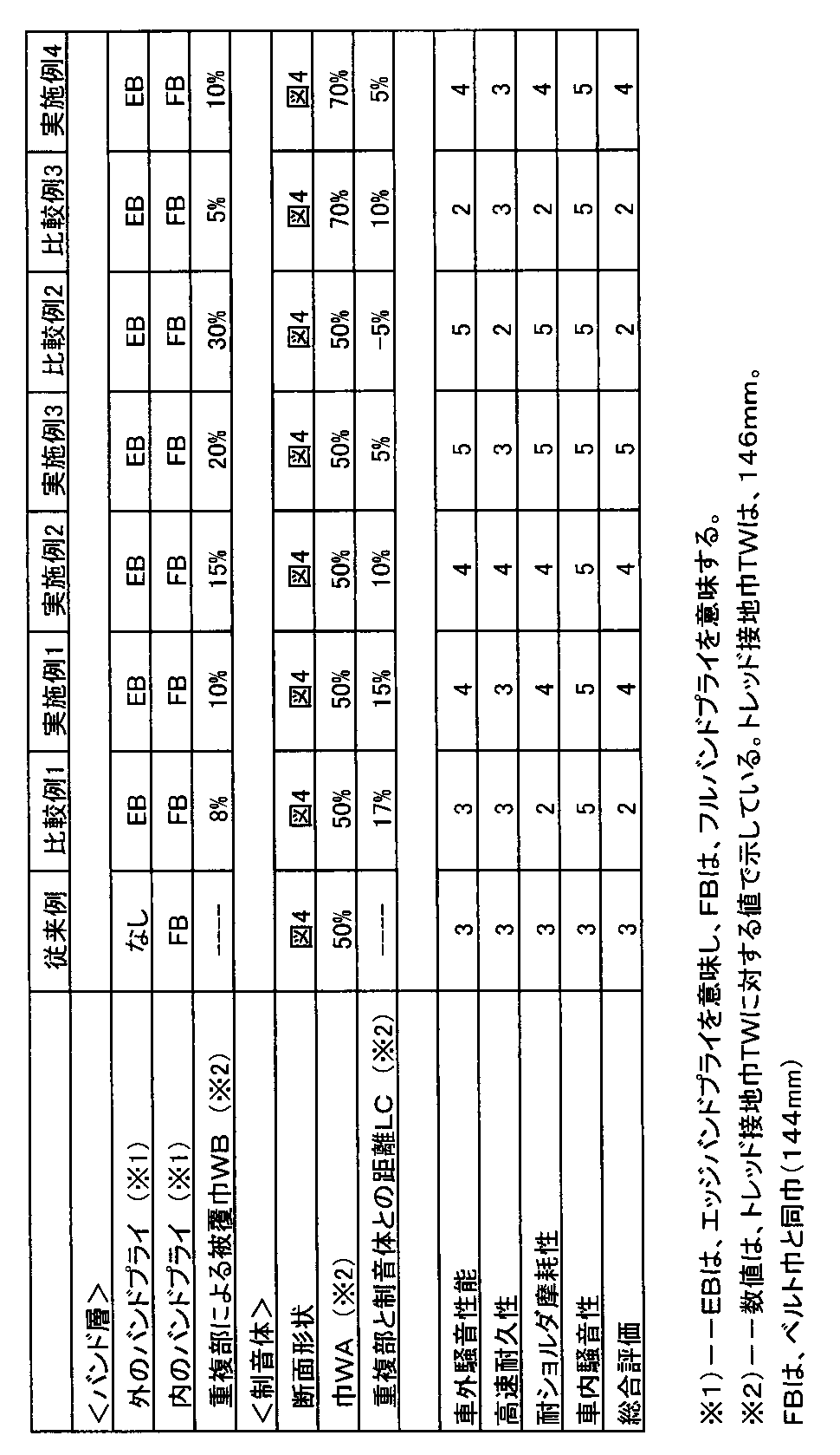
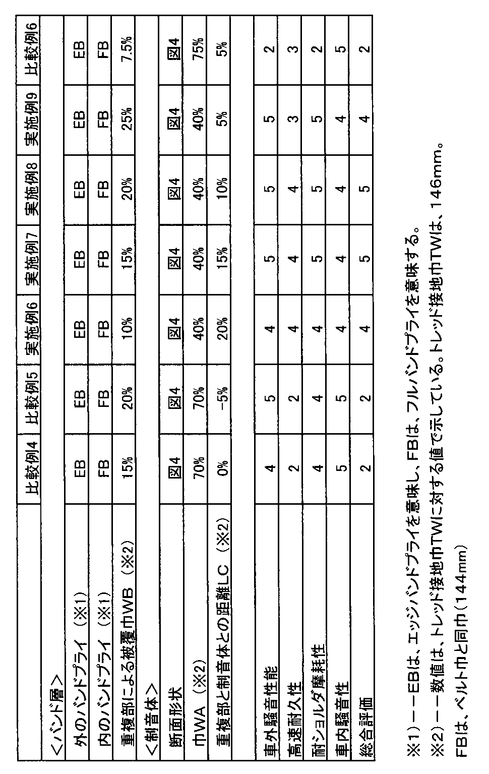
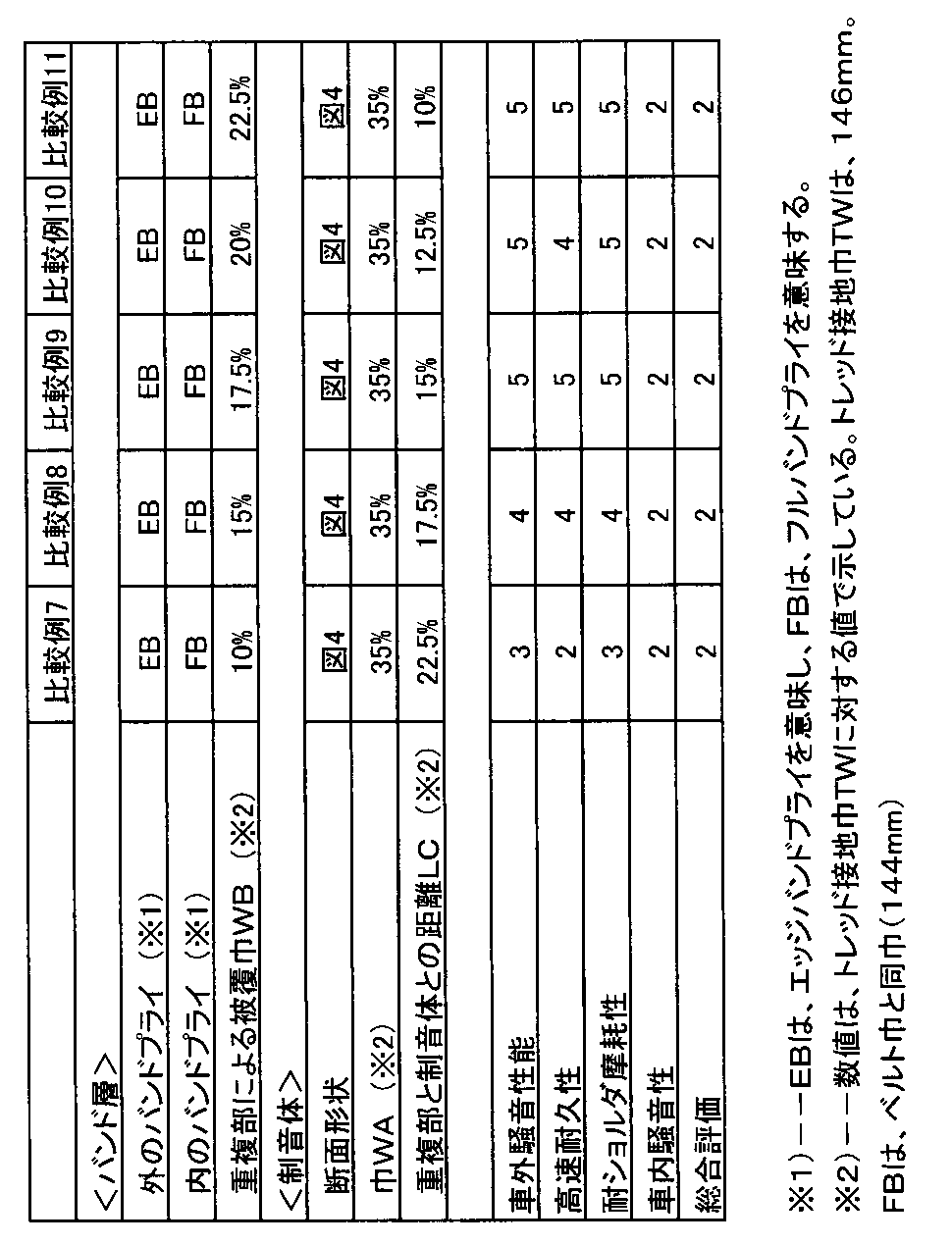
- a pneumatic tire with a sound control body (tire size: 195 / 65R15) having the internal structure of FIG. 1 was prototyped based on the specifications in Table 1. Then, they were tested for external noise performance, high-speed durability, shoulder wear resistance, and in-vehicle noise performance, and the results were evaluated by a five-point method.
- the main common specifications of pneumatic tires are as follows. Number of carcass plies: 2 Code: 1100 dtex / 2 (PET), Cord angle: +88 degrees / -88 degrees Number of cords driven: 50 / 5cm, Belt layer Belt width: 156mm Number of plies: 2 Belt cord: Steel cord (2 + 3 ⁇ 0.20) Cord angle: +20 degrees / -20 degrees Number of cords driven: 40 / 5cm Band layer Band cord: Nylon (2100dtex / 2) Number of cords driven: 50 / 5cm Sound absorber Sponge material: Ether polyurethane polyurethane (specific gravity 0.039) (ESH2 manufactured by Inoac Co., Ltd.) Cross-sectional shape: shown in FIG. Tire circumferential length: 1840mm It was affixed with a double-sided adhesive tape (Ebisu Kasei "E700"). The test method is as follows.
- the tire of the example suppresses shoulder wear, vehicle exterior noise, or deterioration of high-speed durability due to the combination of the sound absorber and the band layer, and comprehensively improves these.
- Table 1 the tire of the example suppresses shoulder wear, vehicle exterior noise, or deterioration of high-speed durability due to the combination of the sound absorber and the band layer, and comprehensively improves these.
Landscapes
- Engineering & Computer Science (AREA)
- Mechanical Engineering (AREA)
- Tires In General (AREA)
Abstract
Description
このカーカスの半径方向外側かつ前記トレッド部の内部に配されるベルト層と、
前記ベルト層の半径方向外側に配されるバンド層と、
前記トレッド部の半径方向内面に取り付きかつタイヤ周方向にのびるスポンジ材からなる帯状の制音体とを具える空気入りタイヤであって、
前記制音体は、そのタイヤ軸方向の巾WAがトレッド接地巾TWの40~70%であり、
しかも前記バンド層は、有機繊維のバンドコードをタイヤ周方向に対して10度以下の角度で螺旋状に巻回させた2枚のバンドプライからなり、かつこの2枚のバンドプライが半径方向内外で重なり合うことにより2層となる重複部を有するとともに、
前記重複部は、前記トレッド接地巾TWの10~25%の被覆巾WBにて前記ベルト層のタイヤ軸方向外端部を覆い、
しかも該重複部のタイヤ軸方向外端は、前記ベルト層のタイヤ軸方向外端Fと同位置又はそれよりタイヤ軸方向外側に位置するとともに、該重複部のタイヤ軸方向内端は、前記制音体のタイヤ軸方向外端Eからタイヤ軸方向外側に距離LCを隔たり、かつこの距離LCを前記トレッド接地巾TWの5~20%としたことを特徴としている。
2 トレッド部
3 サイドウォール部
4 ビード部
5 ビードコア
6 カーカス
7 ベルト層
7A、7B ベルトプライ
9 バンド層
9A、9B バンドプライ
10 制音体
12 重複部
TS トレッド部の半径方向内面
図1において、本実施形態の空気入りタイヤ1は、トレッド部2からサイドウォール部3をへてビード部4のビードコア5に至るカーカス6と、このカーカス6の半径方向外側かつ前記トレッド部2の内部に配されるベルト層7と、該ベルト層7のさらに半径方向外側に配されるバンド層9と、前記トレッド部2の半径方向内面TSに取り付きかつタイヤ周方向にのびるスポンジ材からなる帯状の制音体10とを少なくとも有して構成される。
カーカス
プライ数:2枚、
コード:1100dtex/2(PET)、
コード角:+88度/-88度、
コード打込み数:50本/5cm、
ベルト層
ベルト巾:156mm
プライ数:2枚、
ベルトコード:スチールコード(2+3×0.20)
コード角:+20度/-20度、
コード打込み数:40本/5cm
バンド層
バンドコード:ナイロン(2100dtex/2)
コード打込み数:50本/5cm
制音体
スポンジ材:エーテル系ポリウレタンスポンジ(比重0.039)
((株)イノアック製のESH2)
断面形状:図4に示す。
タイヤ周方向の長さ:1840mm
両面粘着テープ(恵比寿化成社製「E700」)にて貼り付けた。
また、テスト方法は、次の通りである。
タイヤが、内圧200kPaで15×6JJのリムに装着された。各タイヤは、2000ccのFF乗用車の全輪に装着され、直線状のテストコースにおいて、通過速度53km/Hで50mの距離を惰行させた。そして、該テストコースの中間点において、車両の走行中心線から横方向に7.5mを隔て、かつ、路面から高さ1.2mの位置に設置された定置マイクロホンにより通過最大音圧レベルが測定された。評価は、従来例を3点とする5点法であり、値が大きいほど良好であることを示す。
上記車両を用い、ロードノイズ計測路(アスファルト粗面路)を速度60km/hで走行させたときの車内騒音が、運転席窓側耳許位置に設置されたマイクロホンで採取され、240Hz付近の気柱共鳴音のピーク値の音圧レベルが測定された。評価は、従来例を3点とする5点法であり、値が大きいほど良好である。
ドラム走行試験機を用い、内圧280kPa、荷重4.83kNの条件にて、時速80km/hから走行し、10分走行毎に10km/hずつ速度を増加させ、トレッド部に損傷が発生するまでの走行距離が測定された。評価は、従来例を3点とする5点法であり、値が大きいほど良好である。
上記車両を用い、タイヤテストコースを、25000km走行させ、ショルダ溝における摩耗量が測定された。評価は、従来例を3点とする5点法であり、値が大きいほど良好である。
テストの結果は、表1に示される。
Claims (2)
- トレッド部からサイドウォール部を経てビード部のビードコアに至るカーカスと、
該カーカスの半径方向外側かつ前記トレッド部の内部に配されるベルト層と、
前記ベルト層の半径方向外側に配されるバンド層と、
前記トレッド部の半径方向内面に取り付きかつタイヤ周方向にのびるスポンジ材からなる帯状の制音体とを具える空気入りタイヤであって、
前記制音体は、そのタイヤ軸方向の巾WAがトレッド接地巾TWの40~70%であり、
しかも前記バンド層は、有機繊維のバンドコードをタイヤ周方向に対して10度以下の角度で螺旋状に巻回させた2枚のバンドプライからなり、かつこの2枚のバンドプライが半径方向内外で重なり合うことにより2層となる重複部を有するとともに、
前記重複部は、前記トレッド接地巾TWの10~25%の被覆巾WBにて前記ベルト層のタイヤ軸方向外端部を覆い、
しかも該重複部のタイヤ軸方向外端は、前記ベルト層のタイヤ軸方向外端Fと同位置又はそれよりタイヤ軸方向外側に位置するとともに、該重複部のタイヤ軸方向内端は、前記制音体のタイヤ軸方向外端Eからタイヤ軸方向外側に距離LCを隔たり、かつこの距離LCを前記トレッド接地巾TWの5~20%としたことを特徴とする空気入りタイヤ。 - 前記ベルト層は、スチールコードをタイヤ周方向に対して20~30度の角度で傾斜配列した2枚のベルトプライからなり、かつ該ベルトプライは、ベルトコードの傾斜の向きを互いに違えて重置されることを特徴とする請求項1記載の空気入りタイヤ。
Priority Applications (6)
| Application Number | Priority Date | Filing Date | Title |
|---|---|---|---|
| BR112013009181A BR112013009181A2 (pt) | 2010-10-15 | 2011-10-03 | pneu |
| CN201180049866.6A CN103153651B (zh) | 2010-10-15 | 2011-10-03 | 充气轮胎 |
| EP11832436.7A EP2623337B1 (en) | 2010-10-15 | 2011-10-03 | Pneumatic tire |
| RU2013117984/11A RU2566593C2 (ru) | 2010-10-15 | 2011-10-03 | Пневматическая шина |
| US13/822,198 US9180741B2 (en) | 2010-10-15 | 2011-10-03 | Pneumatic tire |
| KR1020137009845A KR101788355B1 (ko) | 2010-10-15 | 2011-10-03 | 공기 타이어 |
Applications Claiming Priority (2)
| Application Number | Priority Date | Filing Date | Title |
|---|---|---|---|
| JP2010232835A JP5685047B2 (ja) | 2010-10-15 | 2010-10-15 | 空気入りタイヤ |
| JP2010-232835 | 2010-10-15 |
Publications (1)
| Publication Number | Publication Date |
|---|---|
| WO2012050000A1 true WO2012050000A1 (ja) | 2012-04-19 |
Family
ID=45938229
Family Applications (1)
| Application Number | Title | Priority Date | Filing Date |
|---|---|---|---|
| PCT/JP2011/072778 Ceased WO2012050000A1 (ja) | 2010-10-15 | 2011-10-03 | 空気入りタイヤ |
Country Status (8)
| Country | Link |
|---|---|
| US (1) | US9180741B2 (ja) |
| EP (1) | EP2623337B1 (ja) |
| JP (1) | JP5685047B2 (ja) |
| KR (1) | KR101788355B1 (ja) |
| CN (1) | CN103153651B (ja) |
| BR (1) | BR112013009181A2 (ja) |
| RU (1) | RU2566593C2 (ja) |
| WO (1) | WO2012050000A1 (ja) |
Cited By (4)
| Publication number | Priority date | Publication date | Assignee | Title |
|---|---|---|---|---|
| WO2018123484A1 (ja) * | 2016-12-28 | 2018-07-05 | 住友ゴム工業株式会社 | 空気入りタイヤ |
| WO2018230146A1 (ja) * | 2017-06-14 | 2018-12-20 | 株式会社ブリヂストン | 吸音部材付き空気入りタイヤ、及びタイヤ・リム組立体 |
| US10723181B2 (en) | 2014-01-23 | 2020-07-28 | The Yokohama Rubber Co., Ltd. | Pneumatic tire with specified tread rubber layer thickness and sound-absorbing member width |
| US11117424B2 (en) | 2016-02-05 | 2021-09-14 | The Yokohama Rubber Co., Ltd. | Pneumatic tire |
Families Citing this family (15)
| Publication number | Priority date | Publication date | Assignee | Title |
|---|---|---|---|---|
| JP5347054B1 (ja) * | 2012-09-03 | 2013-11-20 | 株式会社ブリヂストン | タイヤケースライフ予測システム |
| US10336144B2 (en) | 2014-12-30 | 2019-07-02 | Bridgestone Americas Tire Operations, Llc | Tire electronics securing structures |
| KR20160086157A (ko) * | 2015-01-09 | 2016-07-19 | 금호타이어 주식회사 | 공기입 타이어의 캡플라이 및 그 제조 방법 |
| US11440357B2 (en) | 2016-09-23 | 2022-09-13 | Bridgestone Americas Tire Operations, Llc | Devices for reducing tire noise |
| WO2018074414A1 (ja) * | 2016-10-18 | 2018-04-26 | 住友ゴム工業株式会社 | 空気入りタイヤ |
| KR101940965B1 (ko) * | 2016-12-07 | 2019-01-21 | 스미토모 고무 고교 가부시키가이샤 | 공기입 타이어 |
| CN106515315A (zh) * | 2016-12-07 | 2017-03-22 | 杭州朝阳橡胶有限公司 | 一种具有零度尼龙冠带的全钢工程机械轮胎 |
| JP6536743B2 (ja) * | 2016-12-20 | 2019-07-03 | 住友ゴム工業株式会社 | 空気入りタイヤ |
| JP6524341B2 (ja) * | 2017-01-25 | 2019-06-05 | 住友ゴム工業株式会社 | 空気入りタイヤ |
| KR101861476B1 (ko) * | 2017-03-23 | 2018-07-05 | 한국타이어 주식회사 | 공명음 저감 공기압 타이어 |
| JP6917232B2 (ja) * | 2017-07-24 | 2021-08-11 | 株式会社ブリヂストン | 空気入りタイヤ |
| US11760136B2 (en) | 2018-05-15 | 2023-09-19 | Bridgestone Americas Tire Operations, Llc | Tire with multi-layer insert |
| KR102526920B1 (ko) * | 2021-03-11 | 2023-05-02 | 넥센타이어 주식회사 | 스틸벨트층이 보강되는 공기입 타이어 및 이의 제조방법 |
| JP7786174B2 (ja) | 2021-12-07 | 2025-12-16 | 住友ゴム工業株式会社 | 空気入りタイヤ |
| KR20250089924A (ko) * | 2023-12-12 | 2025-06-19 | 한국타이어앤테크놀로지 주식회사 | 공기입 타이어 |
Citations (4)
| Publication number | Priority date | Publication date | Assignee | Title |
|---|---|---|---|---|
| JP2006264667A (ja) * | 2005-02-28 | 2006-10-05 | Yokohama Rubber Co Ltd:The | 空気入りラジアルタイヤ |
| JP2006306302A (ja) | 2005-04-28 | 2006-11-09 | Sumitomo Rubber Ind Ltd | 空気入りタイヤとリムとの組立体 |
| JP2007161069A (ja) | 2005-12-13 | 2007-06-28 | Sumitomo Rubber Ind Ltd | 制音具付空気入りタイヤ |
| JP2010173573A (ja) * | 2009-01-30 | 2010-08-12 | Yokohama Rubber Co Ltd:The | 乗用車用空気入りラジアルタイヤ |
Family Cites Families (14)
| Publication number | Priority date | Publication date | Assignee | Title |
|---|---|---|---|---|
| JPH0655913A (ja) * | 1992-08-07 | 1994-03-01 | Bridgestone Corp | 空気入りタイヤ |
| JP3393520B2 (ja) * | 1994-06-10 | 2003-04-07 | 住友ゴム工業株式会社 | 空気入りラジアルタイヤの製造方法 |
| JP3339757B2 (ja) * | 1995-01-10 | 2002-10-28 | 住友ゴム工業株式会社 | 空気入りタイヤ |
| JP4287530B2 (ja) | 1999-02-17 | 2009-07-01 | 住友ゴム工業株式会社 | 空気入りラジアルタイヤ |
| JP3622957B2 (ja) * | 2001-08-02 | 2005-02-23 | 住友ゴム工業株式会社 | 空気入りタイヤとリムとの組立体 |
| JP3943506B2 (ja) * | 2003-01-24 | 2007-07-11 | 住友ゴム工業株式会社 | 空気入りタイヤ |
| JP4723198B2 (ja) * | 2004-03-22 | 2011-07-13 | 住友ゴム工業株式会社 | 空気入りタイヤ |
| JP5072368B2 (ja) * | 2005-01-21 | 2012-11-14 | 株式会社ブリヂストン | 空気入りラジアルタイヤ |
| US20070012394A1 (en) | 2005-07-13 | 2007-01-18 | The Yokohama Rubber Co., Ltd. | Pneumatic radial tire |
| EP1795378B1 (en) * | 2005-12-08 | 2011-05-25 | Sumitomo Rubber Industries, Ltd. | Pneumatic tire with noise damper |
| JP4921786B2 (ja) * | 2005-12-09 | 2012-04-25 | 住友ゴム工業株式会社 | 空気入りタイヤ |
| JP4783135B2 (ja) * | 2005-12-13 | 2011-09-28 | 住友ゴム工業株式会社 | 制音具付空気入りタイヤ |
| JP5005978B2 (ja) * | 2006-07-28 | 2012-08-22 | 住友ゴム工業株式会社 | ランフラットタイヤ |
| JP2008279841A (ja) * | 2007-05-09 | 2008-11-20 | Toyo Tire & Rubber Co Ltd | 空気入りラジアルタイヤ |
-
2010
- 2010-10-15 JP JP2010232835A patent/JP5685047B2/ja active Active
-
2011
- 2011-10-03 CN CN201180049866.6A patent/CN103153651B/zh active Active
- 2011-10-03 US US13/822,198 patent/US9180741B2/en active Active
- 2011-10-03 KR KR1020137009845A patent/KR101788355B1/ko active Active
- 2011-10-03 RU RU2013117984/11A patent/RU2566593C2/ru active
- 2011-10-03 WO PCT/JP2011/072778 patent/WO2012050000A1/ja not_active Ceased
- 2011-10-03 EP EP11832436.7A patent/EP2623337B1/en active Active
- 2011-10-03 BR BR112013009181A patent/BR112013009181A2/pt not_active IP Right Cessation
Patent Citations (4)
| Publication number | Priority date | Publication date | Assignee | Title |
|---|---|---|---|---|
| JP2006264667A (ja) * | 2005-02-28 | 2006-10-05 | Yokohama Rubber Co Ltd:The | 空気入りラジアルタイヤ |
| JP2006306302A (ja) | 2005-04-28 | 2006-11-09 | Sumitomo Rubber Ind Ltd | 空気入りタイヤとリムとの組立体 |
| JP2007161069A (ja) | 2005-12-13 | 2007-06-28 | Sumitomo Rubber Ind Ltd | 制音具付空気入りタイヤ |
| JP2010173573A (ja) * | 2009-01-30 | 2010-08-12 | Yokohama Rubber Co Ltd:The | 乗用車用空気入りラジアルタイヤ |
Cited By (6)
| Publication number | Priority date | Publication date | Assignee | Title |
|---|---|---|---|---|
| US10723181B2 (en) | 2014-01-23 | 2020-07-28 | The Yokohama Rubber Co., Ltd. | Pneumatic tire with specified tread rubber layer thickness and sound-absorbing member width |
| US11117424B2 (en) | 2016-02-05 | 2021-09-14 | The Yokohama Rubber Co., Ltd. | Pneumatic tire |
| WO2018123484A1 (ja) * | 2016-12-28 | 2018-07-05 | 住友ゴム工業株式会社 | 空気入りタイヤ |
| JPWO2018123484A1 (ja) * | 2016-12-28 | 2018-12-27 | 住友ゴム工業株式会社 | 空気入りタイヤ |
| US10647168B1 (en) | 2016-12-28 | 2020-05-12 | Sumitomo Rubber Industries, Ltd. | Pneumatic tire |
| WO2018230146A1 (ja) * | 2017-06-14 | 2018-12-20 | 株式会社ブリヂストン | 吸音部材付き空気入りタイヤ、及びタイヤ・リム組立体 |
Also Published As
| Publication number | Publication date |
|---|---|
| JP5685047B2 (ja) | 2015-03-18 |
| RU2566593C2 (ru) | 2015-10-27 |
| US20130160914A1 (en) | 2013-06-27 |
| EP2623337B1 (en) | 2018-06-27 |
| CN103153651A (zh) | 2013-06-12 |
| US9180741B2 (en) | 2015-11-10 |
| EP2623337A4 (en) | 2017-07-26 |
| JP2012086600A (ja) | 2012-05-10 |
| EP2623337A1 (en) | 2013-08-07 |
| CN103153651B (zh) | 2016-05-18 |
| KR101788355B1 (ko) | 2017-10-19 |
| BR112013009181A2 (pt) | 2018-05-02 |
| RU2013117984A (ru) | 2014-11-20 |
| KR20130118871A (ko) | 2013-10-30 |
Similar Documents
| Publication | Publication Date | Title |
|---|---|---|
| JP5685047B2 (ja) | 空気入りタイヤ | |
| US10195904B2 (en) | Pneumatic tire | |
| JP4318419B2 (ja) | 空気入りラジアルタイヤ | |
| JP5858069B2 (ja) | 空気入りタイヤ | |
| JP7003627B2 (ja) | 空気入りタイヤ及びタイヤ・リム組立体 | |
| US10035380B2 (en) | Pneumatic tire | |
| JP7482963B2 (ja) | 乗用車用空気入りラジアルタイヤ | |
| JP5458778B2 (ja) | 空気入りタイヤ | |
| WO2020121573A1 (ja) | 乗用車用空気入りラジアルタイヤ | |
| JP5947783B2 (ja) | 空気入りタイヤ | |
| JP6988242B2 (ja) | 空気入りタイヤ | |
| JP2015113043A (ja) | 空気入りタイヤ | |
| JP7529962B2 (ja) | 空気入りタイヤ | |
| JP6010932B2 (ja) | 空気入りタイヤ | |
| JP6007551B2 (ja) | 空気入りタイヤ | |
| JP4989210B2 (ja) | 自動二輪車用タイヤ | |
| JP2012111382A (ja) | 制音具付き空気入りタイヤ | |
| JP4413506B2 (ja) | 空気入りタイヤ | |
| JP2012218565A (ja) | 空気入りタイヤ | |
| JP4234912B2 (ja) | 空気入りラジアルタイヤ | |
| JP6001514B2 (ja) | 空気入りタイヤ | |
| JP2013173395A (ja) | 空気入りタイヤ | |
| JP7786174B2 (ja) | 空気入りタイヤ | |
| JP2007237922A (ja) | 空気入りタイヤ | |
| JP7448779B2 (ja) | 空気入りタイヤ |
Legal Events
| Date | Code | Title | Description |
|---|---|---|---|
| WWE | Wipo information: entry into national phase |
Ref document number: 201180049866.6 Country of ref document: CN |
|
| 121 | Ep: the epo has been informed by wipo that ep was designated in this application |
Ref document number: 11832436 Country of ref document: EP Kind code of ref document: A1 |
|
| WWE | Wipo information: entry into national phase |
Ref document number: 13822198 Country of ref document: US |
|
| NENP | Non-entry into the national phase |
Ref country code: DE |
|
| ENP | Entry into the national phase |
Ref document number: 20137009845 Country of ref document: KR Kind code of ref document: A |
|
| WWE | Wipo information: entry into national phase |
Ref document number: 2011832436 Country of ref document: EP |
|
| ENP | Entry into the national phase |
Ref document number: 2013117984 Country of ref document: RU Kind code of ref document: A |
|
| REG | Reference to national code |
Ref country code: BR Ref legal event code: B01A Ref document number: 112013009181 Country of ref document: BR |
|
| ENP | Entry into the national phase |
Ref document number: 112013009181 Country of ref document: BR Kind code of ref document: A2 Effective date: 20130415 |