WO2012066732A1 - 電子装置 - Google Patents
電子装置 Download PDFInfo
- Publication number
- WO2012066732A1 WO2012066732A1 PCT/JP2011/005960 JP2011005960W WO2012066732A1 WO 2012066732 A1 WO2012066732 A1 WO 2012066732A1 JP 2011005960 W JP2011005960 W JP 2011005960W WO 2012066732 A1 WO2012066732 A1 WO 2012066732A1
- Authority
- WO
- WIPO (PCT)
- Prior art keywords
- power supply
- backplane
- circuit board
- electronic device
- bus bar
- Prior art date
- Legal status (The legal status is an assumption and is not a legal conclusion. Google has not performed a legal analysis and makes no representation as to the accuracy of the status listed.)
- Ceased
Links
Images


Classifications
-
- H—ELECTRICITY
- H05—ELECTRIC TECHNIQUES NOT OTHERWISE PROVIDED FOR
- H05K—PRINTED CIRCUITS; CASINGS OR CONSTRUCTIONAL DETAILS OF ELECTRIC APPARATUS; MANUFACTURE OF ASSEMBLAGES OF ELECTRICAL COMPONENTS
- H05K7/00—Constructional details common to different types of electric apparatus
- H05K7/20—Modifications to facilitate cooling, ventilating, or heating
- H05K7/20009—Modifications to facilitate cooling, ventilating, or heating using a gaseous coolant in electronic enclosures
- H05K7/20136—Forced ventilation, e.g. by fans
-
- H—ELECTRICITY
- H05—ELECTRIC TECHNIQUES NOT OTHERWISE PROVIDED FOR
- H05K—PRINTED CIRCUITS; CASINGS OR CONSTRUCTIONAL DETAILS OF ELECTRIC APPARATUS; MANUFACTURE OF ASSEMBLAGES OF ELECTRICAL COMPONENTS
- H05K7/00—Constructional details common to different types of electric apparatus
- H05K7/20—Modifications to facilitate cooling, ventilating, or heating
-
- H—ELECTRICITY
- H05—ELECTRIC TECHNIQUES NOT OTHERWISE PROVIDED FOR
- H05K—PRINTED CIRCUITS; CASINGS OR CONSTRUCTIONAL DETAILS OF ELECTRIC APPARATUS; MANUFACTURE OF ASSEMBLAGES OF ELECTRICAL COMPONENTS
- H05K7/00—Constructional details common to different types of electric apparatus
- H05K7/02—Arrangements of circuit components or wiring on supporting structure
- H05K7/06—Arrangements of circuit components or wiring on supporting structure on insulating boards, e.g. wiring harnesses
-
- H—ELECTRICITY
- H05—ELECTRIC TECHNIQUES NOT OTHERWISE PROVIDED FOR
- H05K—PRINTED CIRCUITS; CASINGS OR CONSTRUCTIONAL DETAILS OF ELECTRIC APPARATUS; MANUFACTURE OF ASSEMBLAGES OF ELECTRICAL COMPONENTS
- H05K7/00—Constructional details common to different types of electric apparatus
- H05K7/14—Mounting supporting structure in casing or on frame or rack
- H05K7/1438—Back panels or connecting means therefor; Terminals; Coding means to avoid wrong insertion
- H05K7/1452—Mounting of connectors; Switching; Reinforcing of back panels
-
- H—ELECTRICITY
- H05—ELECTRIC TECHNIQUES NOT OTHERWISE PROVIDED FOR
- H05K—PRINTED CIRCUITS; CASINGS OR CONSTRUCTIONAL DETAILS OF ELECTRIC APPARATUS; MANUFACTURE OF ASSEMBLAGES OF ELECTRICAL COMPONENTS
- H05K7/00—Constructional details common to different types of electric apparatus
- H05K7/14—Mounting supporting structure in casing or on frame or rack
- H05K7/1438—Back panels or connecting means therefor; Terminals; Coding means to avoid wrong insertion
- H05K7/1457—Power distribution arrangements
-
- H—ELECTRICITY
- H05—ELECTRIC TECHNIQUES NOT OTHERWISE PROVIDED FOR
- H05K—PRINTED CIRCUITS; CASINGS OR CONSTRUCTIONAL DETAILS OF ELECTRIC APPARATUS; MANUFACTURE OF ASSEMBLAGES OF ELECTRICAL COMPONENTS
- H05K7/00—Constructional details common to different types of electric apparatus
- H05K7/20—Modifications to facilitate cooling, ventilating, or heating
- H05K7/20709—Modifications to facilitate cooling, ventilating, or heating for server racks or cabinets; for data centers, e.g. 19-inch computer racks
- H05K7/20718—Forced ventilation of a gaseous coolant
- H05K7/20727—Forced ventilation of a gaseous coolant within server blades for removing heat from heat source
Definitions
- the present invention relates to an electronic device represented by a LAN switch, a router, a server, and the like, and more particularly to a backplane structure of the electronic device.
- a network communication device such as a LAN switch or a router includes a circuit board unit having an interface function for packet transfer, a circuit board unit having a function of switching a packet to a desired port, and a circuit board having a function of controlling packet transfer. Units etc. These circuit board units are connected to a relay circuit board (so-called backplane) disposed in the apparatus via a connector, and signal exchange and power feeding between the circuit board units are executed via this backplane.
- backplane relay circuit board
- AC 100V or AC 200V is often applied to AC machines
- DC 48V is often applied to DC machines.
- This voltage is input to the front power supply unit of the apparatus, and the front power supply unit outputs DC48V, and this DC48V output is generally supplied to each circuit board unit via the backplane.
- circuit board units are formed for each function. These circuit board units are backplanes arranged in the apparatus via connectors. The signal exchange and power supply between the circuit board units are performed through the backplane.
- the power supply of the server is often applied with AC100V or AC200V. This voltage is input to the front power supply unit of the apparatus, and the front power supply unit outputs DC12V, and this DC12V output is generally supplied to each circuit board unit via the backplane.
- NEBS Network Equipment Building System
- Patent Document 1 the number of electronic components to be mounted has increased dramatically as the functionality of electronic devices such as servers has increased, and the current required to operate the electronic device has also increased. Yes. At the same time, electronic devices are being made smaller and lighter, and demands for smaller and lighter electronic components used in electronic devices are increasing. Therefore, it is desired to provide a power supply bus bar structure that is smaller and allows a larger current to flow, but heat generation of the power supply bus bar due to a large current flow has been a problem.
- Patent Document 1 a bar-shaped power supply bus bar is used, a power source and a load are connected in a one-to-one relationship, and a cooling fin is further provided on the power supply bus bar, thereby forcibly air-cooling the structure. Is adopted.
- Patent Document 2 when a large current is supplied to a circuit board unit in an electronic device, the power supply by a normal connector increases the number of power supply connector pins or decreases the number of signal connector pins. It had to be turned for supply.
- a bar-shaped power supply bar having a plurality of conductive layers and insulating layers, such as a multilayer circuit board, is connected between connectors on a backplane by conductive pin contacts and conductive spacers.
- a connector structure is adopted in which the conductive pin contact and the circuit board unit are electrically connected to each other and supplied with a large current.
- the present invention was made to solve the above-described new problem, and in an electronic device, while adopting a front / rear intake / exhaust system structure, it is possible to suppress power loss and heat generation in a power feeding path, and
- An object of the present invention is to provide a backplane structure that reinforces mechanical strength and further reduces costs.
- the present invention can solve at least a part of the problems described above as the following forms or application examples.
- a circuit board unit a backplane that connects the circuit board to a front surface; a power supply bus bar that connects to a back surface of the backplane; and a power supply unit that connects to the power supply bus bar.
- An electronic device wherein the bus bar is provided with a vent hole, and the bus bar is further provided with a heat dissipation projection.
- One side of the flat power supply bus bar is a flat surface, is in close contact with the back plane, is electrically and mechanically connected at multiple points, and has wing-like projections on the other side.
- power loss and heat generation of the backplane can be suppressed, the mechanical strength can be reinforced, and a wide ventilation opening can be secured for the backplane.
- Embodiment 1 is an example of a configuration of an electronic device in Embodiment 1.
- 3 is an example of a power supply bus bar according to the first embodiment.
- 3 is an example of a power supply bus bar according to the first embodiment.
- 6 is an example of a configuration of an electronic device according to a second embodiment.
- 4 is an example of a power supply bus bar according to the second embodiment.
- 4 is an example of a power supply bus bar according to the second embodiment.
- 7 is an example of a configuration of an electronic device according to a third embodiment.
- 6 is an example of a power supply bus bar according to a third embodiment.
- 6 is an example of a power supply bus bar according to a third embodiment.
- 10 is an example of a configuration of an electronic device according to a fourth embodiment.
- 10 is an example of a power supply bus bar according to a fourth embodiment.
- 10 is an example of a power supply bus bar according to a fourth embodiment.
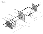
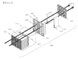
- FIG. 1A is a diagram schematically showing a configuration of the electronic device 100 according to the first embodiment of the present invention.
- FIG. 2A is a diagram schematically illustrating the configuration of the electronic device 200 according to the second embodiment of the present invention.
- FIG. 3A is a diagram schematically illustrating a configuration of the electronic device 300 according to the third embodiment of the present invention.
- FIG. 4A is a diagram schematically illustrating a configuration of the electronic device 400 according to the fourth embodiment of the present invention.
- the electronic devices 100 to 400 function as network communication devices that perform packet transfer in a computer network.
- FIG. 1A shows a front perspective view of the electronic device 100.
- the electronic device 100 includes a plurality of circuit board units 120, a plurality of front power supply units 130, a plurality of cooling units 140, a backplane 150, and a power supply bus bar 160 inside a housing 110.
- the electronic device 100 of the present embodiment has a plurality of circuit board units 120, which are mounted in a horizontal state from the front of the device.
- the circuit board unit 120 is configured by a circuit board on which a semiconductor element is mounted, and realizes various functions for performing packet transfer. For example, a circuit board unit that performs external interface control, packet destination search, packet transfer processing, and the like, a circuit board unit that switches a packet to a desired port, and a CPU, and a circuit that performs basic control of the electronic device 100 It has a substrate unit.
- circuit board units 120 have ventilation holes 121 through which cooling air is passed to the front side of the apparatus.
- Each circuit board unit 120 has a backplane connector 122 on the side facing the front side of the apparatus, and the backplane connector 122 and the backplane 150 are connected to exchange signals between the circuit board units. Power feeding is executed.
- the number of circuit board units 120 mounted is not limited to the number shown in the figure.
- the electronic device 100 of the present embodiment has a plurality of front power supply units 130 in order to increase the reliability of the device, and realizes redundancy. These are mounted horizontally from the rear surface of the apparatus.
- AC 100 V or AC 200 V is applied to the front power supply unit 130 in the AC machine
- DC 48 V is applied to the front power supply unit 130 in the DC machine
- DC 48 V is often output by performing AC / DC conversion processing to DC / DC conversion processing.
- the output of the front power supply unit 130 is connected to the backplane 150 by a power supply connector 131, and DC48V is generally supplied to each circuit board unit via the backplane.
- DC48V is generally supplied to each circuit board unit via the backplane.
- the output voltage of the front power supply unit 130 is becoming mainstream DC12V.
- the number of the front power supply units 130 to be mounted is not limited to the number in FIG.
- the circuit board unit 120 is mounted in a horizontal state from the front of the device, and the flow of cooling air to the semiconductor element has a structure of front and rear intake and exhaust, and the cooling air is forced to flow.
- the cooling unit 140 configured by Fan for this purpose is installed on the rear surface side of the housing 110. Note that the number of these cooling units 140 mounted is not limited to the number shown in the figure. Further, although the number of front-side interfaces is suppressed, it may be arranged on the front side of the housing 110. The same applies to the other embodiments.
- the circuit board unit 120 and the front power supply unit 130 are connected to a backplane 150 disposed in the apparatus via a connector.
- the backplane 150 is usually constituted by a multilayer circuit board and mainly has two roles. The first function is to connect the plurality of circuit board units 120 with wiring and exchange signals. The second function is to supply DC 48V to DC 12V generated by the front power supply unit 130 to each circuit board unit 120.
- the electronic device 100 of the present embodiment employs a front / rear intake / exhaust cooling structure, and it is necessary to provide a ventilation port 151 for passing cooling air through the backplane 150. Therefore, a power supply layer and a ground layer for power supply are provided. Even if the number of layers is increased, there arises a problem that a sufficient current path cannot be obtained. For this reason, a power supply bus bar 160 described later is laid.
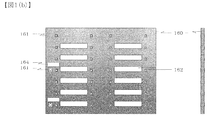
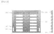
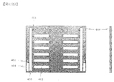
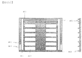
- FIG. 1B and FIG. 1C show a power supply bus bar 160.
- the power supply bus bar 160 is made of a metal such as copper or aluminum, and is electrically and mechanically connected to the power supply layer or the ground layer of the backplane 150 by screwing or soldering using the power supply terminal 161.
- a plurality of circuit board units 120 and a plurality of front power supply units 130 are connected at multiple points by a plurality of power supply terminals 161.
- power supply to the circuit board unit 120 is often performed in a power supply layer and a ground layer laid on a backplane 150 formed of a multilayer circuit board, but when the amount of current to be supplied is large, Even if the number of layers of the power supply layer and the ground layer is increased, power loss cannot be ignored and the cost increases. Therefore, the power supply bus bar 160 is often laid to supply power. However, even if the power supply bus bar 160 is laid to reduce power loss, heat generation remains a problem.
- the power supply bus bar 160 is provided with the wing-like protrusions 163 and the power supply bus bar 160 is applied with cooling air, thereby supplying power.
- the problem of power loss and heat generation of the bus bar 160 can be solved, and the opening area of the ventilation port 151 of the backplane 150 and the ventilation port 162 of the power supply bus bar 160 can be sufficiently increased, thereby improving the cooling performance of the apparatus. It becomes possible to make it.
- the power supply bus bar 160 is closely attached to the backplane 150 and electrically and mechanically connected at multiple points, thereby making it possible to reinforce the deterioration of rigidity due to the ventilation holes 151 provided in the backplane 150. Become.
- the power supply bus bar 160 is provided with a power connector connection port 164 for connecting the front power unit 130 to the back plane 150 from the rear surface of the apparatus.
- the shape of the protrusions provided to the power supply bus bar 160 is not limited to the wing-like protrusions 163, and for example, the shape of a sword-like protrusion or a bellows-like protrusion may be adopted.
- the power supply bus bar 160 may have a structure in which a portion other than the portion electrically connected to the backplane 150 is coated with an insulating material to prevent a short circuit.
- the exhaust heat performance is enhanced by connecting the power supply bus bar to the backplane 150 to increase the opening area of the vent 162 and by providing the protrusion 163.
- the protrusion 163 serves as a reinforcement to suppress the deterioration of rigidity due to the increase in the opening area of the vent 162.
- the 12V power supply method is assumed, but the same effect can naturally be obtained with the 48V power supply method and other power supply methods. The same applies to other embodiments.
- the potential difference between the potential applied to the power supply bus bar 160 and the ground potential becomes 4.5V or more and 16V or less.
- the potential difference between the potential applied to the power supply bus bar 160 and the ground potential becomes 36V or more and 75V or less.
- FIG. 2A shows a front perspective view of the electronic device 200.
- the electronic device 200 includes a plurality of circuit board units 220, a plurality of front power supply units 230, a plurality of cooling units 240, a backplane 250, and a power supply bus bar 260 inside a housing 210.
- the electronic device 200 of this embodiment is a modification of the electronic device 100 of the first embodiment.
- a significant difference from the electronic device 100 of the first embodiment is that the front power supply unit 230 is mounted vertically on the left and right sides of the rear surface of the device to secure a passage for cooling air.
- This structure makes it possible to improve the cooling performance of the apparatus because the direction of the cooling air is linear compared to the electronic apparatus 100 of the first embodiment.
- Other structures are the same as those of the electronic device 100 of the first embodiment. Note that the number of circuit board units 220, front power supply units 230, and cooling units 240 in the present embodiment is not limited to the number in FIG.
- FIG. 2B and FIG. 2C show the power supply bus bar 260.
- the power supply bus bar 260 of the present embodiment differs greatly from the power supply bus bar 160 of the first embodiment in that the front power supply unit 230 is mounted vertically on the left and right of the rear surface of the apparatus, and a cooling air passage is secured.
- the power connector connection port 264 is arranged on the left and right.
- the cooling performance is improved and the rigidity deterioration is suppressed by securing the cooling air passage for the front power supply unit 230 without attaching a projection for exhaust heat. is doing.
- the ventilation performance of the power supply bus bar 260 is further enlarged, and the cooling performance is improved more than the configuration of FIG. 2B by providing a projection for waste heat.
- the protrusions suppress the deterioration of rigidity of the backplane 250 and the power supply bus bar 260.
- Other structures and effects are the same as those of the electronic device 100 of the first embodiment.
- FIG. 3A shows a front perspective view of the electronic device 300.
- the electronic device 300 includes a plurality of circuit board units 320, a plurality of front power supply units 330, a plurality of cooling units 340, a backplane 350, and a power supply bus bar 360 inside the housing 310.
- the electronic device 300 of this embodiment differs greatly from the electronic device 100 of the first embodiment and the electronic device 200 of the second embodiment in that the circuit board unit 320 is mounted in a horizontal state from the front of the device, and the device It is a point that adopts a structure that is mounted vertically in the center of the rear surface.
- the circuit board unit 320 mounted on the rear surface of the apparatus is, for example, a circuit board unit having a function as a crossbar switch.
- the crossbar switch is a circuit board unit having a function of switching a packet arrived from the circuit board unit 320 mounted from the front of the apparatus to a desired port.
- the signal wiring length can be shortened, so that the speed and performance of the device can be improved.
- the front power supply unit 330 is mounted vertically on the left and right of the rear surface of the apparatus, and a cooling air passage is secured.
- circuit board units 320, front power supply units 330, and cooling units 340 mounted in the present embodiment is not limited to the number mounted in the drawing.
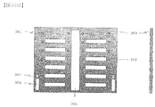
- FIG. 3B and FIG. 3C show the power supply bus bar 360.
- the power supply bus bar 360 is made of a metal such as copper or aluminum, and is electrically and mechanically connected to the power supply layer or the ground layer of the backplane 350 by screwing or soldering using the power supply terminal 361.
- a plurality of circuit board units 320 and a plurality of front power supply units 330 are connected at multiple points by a plurality of power supply terminals 361.
- power supply to the circuit board unit 320 is often performed in a power supply layer and a ground layer laid on a backplane 350 formed of a multilayer circuit board, but when the amount of current to be supplied is large, Even if the number of layers of the power supply layer and the ground layer is increased, power loss cannot be ignored and the cost is increased. Therefore, the power supply bus bar 360 is often laid to supply power.
- the cooling performance is improved by mounting the front power supply unit 330 vertically on the left and right sides of the rear surface of the apparatus to secure a passage for cooling air.
- the power supply bus bar 360 is provided with the wing-like projections 363 and the power supply bus bar 360 is configured to apply cooling air to the power supply bus bar 360.
- the problem of power loss and heat generation of the bus bar 360 can be solved, and the opening area of the ventilation port 351 of the backplane 350 and the ventilation port 362 of the power supply bus bar 360 can be sufficiently increased, thereby further improving the cooling performance of the apparatus. It becomes possible to improve.
- the power supply bus bar 360 is brought into close contact with the back plane 350 and electrically and mechanically connected at multiple points, whereby it is possible to reinforce the deterioration of rigidity due to the vent holes 351 provided in the back plane 350. Become.
- the power supply bus bar 360 is provided with a power connector connecting port 364 and a back plane connector connecting port 365 for connecting the front power unit 330 and the circuit board unit 320 to the back plane 150 from the rear surface of the apparatus.
- the shape of the protrusion provided to the power supply bus bar 360 is not limited to the wing-shaped protrusion 363, and for example, the shape of a sword-shaped protrusion or a bellows-like protrusion may be employed.
- the power supply bus bar 360 may have a structure in which a portion other than the portion electrically connected to the backplane 350 is coated with an insulating material to prevent a short circuit.
- FIG. 4A shows a front perspective view of the electronic device 400.
- the electronic device 400 includes a plurality of circuit board units 420, a plurality of front power supply units 430, a plurality of cooling units 440, a backplane 450, and a power supply bus bar 460 inside the housing 410.
- the electronic device 400 of this embodiment is a modification of the electronic device 300 of the third embodiment.
- a significant difference from the electronic device 300 of the third embodiment is that the circuit board unit 420 is mounted vertically on the left and right sides of the rear surface of the device to secure a passage for cooling air.
- the circuit board unit 420 is mounted vertically on the left and right sides of the rear surface of the device to secure a passage for cooling air.
- circuit board units 420, front power supply units 430, and cooling units 440 mounted in the present embodiment is not limited to the number mounted in the drawing.
- FIG. 4B and FIG. 4C show the power supply bus bar 460.
- the power supply bus bar 460 of the present embodiment differs greatly from the power supply bus bar 360 of the third embodiment in that the circuit board unit 420 is mounted vertically on the left and right sides of the rear surface of the apparatus, thereby securing a cooling air passage.
- the backplane connector connection port 465 is arranged on the left and right.
- Other structures and effects are the same as those of the electronic device 300 of the third embodiment.
- the circuit board unit is mounted in a horizontal state from the front surface of the device, and the flow of cooling air flows from the ventilation opening on the front surface of the device. It has a structure of front and rear intake / exhaust air that is sucked in, passes through the vent of the backplane and the vent of the power supply bus bar, and is exhausted to the rear surface of the device.
- the power supply bus bar has a wing-like projection and the power supply bus bar
- the circuit board unit is mounted in a horizontal state from the front surface of the device, and is also mounted in a vertical state from the rear surface of the device,
- the cooling air flow is taken from the air vents on the front of the device, passes through the vents on the backplane and the power supply bus bar, and is exhausted to the rear of the device.
- the problem of power loss and heat generation of the power supply bus bar can be solved by providing the wing-like projections and the structure in which the cooling bus is applied to the power supply bus bar.
- the power supply bus bar is brought into close contact with the back plane and electrically and mechanically connected at multiple points, whereby it is possible to reinforce the deterioration of rigidity due to the vent holes provided in the back plane. Furthermore, since the number of power supply layers and ground layers laid on the backplane can be reduced, the cost can also be reduced.
- a method is adopted in which air is sucked from the vent on the front of the apparatus, exhausted through the vent on the backplane and the vent on the power supply bus bar, and exhausted to the rear of the apparatus.
- a method of blowing air from the rear of the apparatus and exhausting it to the front of the apparatus can be adopted.
- the power supply bus bar itself has a wing-like protrusion, but the problem of heat generation is solved by attaching a separate cooling fin to the power supply bus bar.
- the structure to do can also be taken.
- a network communication device is assumed, but the present invention can also be applied to an information processing device such as a server without departing from the gist of the present invention.
- Power supply bus bar 261 ... Power supply terminal 262 ⁇ Ventilation port 263 ⁇ Wings 264 ⁇ Power connector connection port 300 ⁇ ⁇ ⁇ Electronic device 310 ⁇ ⁇ ⁇ Case 320 ⁇ ⁇ ⁇ Circuit board unit 321 ⁇ ⁇ ⁇ Ventilation port 322 ⁇ ⁇ ⁇ Back Plain connector 330 ... Front power supply unit 331 ... Power supply connector 340 ... Cooling unit 350 ... Backplane 351 ... Ventilation hole 360 ... Power supply bus bar 361 ... Power supply terminal 362 ... Ventilation port 363 ... Feather projection 364 ... Power connector connection port 365 ... Backplane connector connection port 400 ... Electronic device 410 ... Housing 420 ... Circuit board unit 421 ...
- Ventilation hole 422 ... Backplane connector 430 Front power supply unit 431 ... Power supply connector 440 ... Cooling unit Knit 450 ... Backplane 451 ... Ventilation port 460 ... Power supply bus bar 461 ... Power supply terminal 462 ; Ventilation port 463 ... Wing-like projection 464 ... Power supply connector connection port 465 ..Backplane connector connection port
Landscapes
- Engineering & Computer Science (AREA)
- Microelectronics & Electronic Packaging (AREA)
- Physics & Mathematics (AREA)
- Thermal Sciences (AREA)
- Computer Hardware Design (AREA)
- General Engineering & Computer Science (AREA)
- Power Engineering (AREA)
- Cooling Or The Like Of Electrical Apparatus (AREA)
- Mounting Of Printed Circuit Boards And The Like (AREA)
Abstract
Description
110・・・筐体
120・・・回路基板ユニット
121・・・通風口
122・・・バックプレーンコネクタ
130・・・フロント電源ユニット
131・・・電源コネクタ
140・・・冷却ユニット
150・・・バックプレーン
151・・・通風口
160・・・給電用バスバー
161・・・給電端子
162・・・通風口
163・・・羽状突起物
164・・・電源コネクタ接続口
200・・・電子装置
210・・・筐体
220・・・回路基板ユニット
221・・・通風口
222・・・バックプレーンコネクタ
230・・・フロント電源ユニット
231・・・電源コネクタ
240・・・冷却ユニット
250・・・バックプレーン
251・・・通風口
260・・・給電用バスバー
261・・・給電端子
262・・・通風口
263・・・羽状突起物
264・・・電源コネクタ接続口
300・・・電子装置
310・・・筐体
320・・・回路基板ユニット
321・・・通風口
322・・・バックプレーンコネクタ
330・・・フロント電源ユニット
331・・・電源コネクタ
340・・・冷却ユニット
350・・・バックプレーン
351・・・通風口
360・・・給電用バスバー
361・・・給電端子
362・・・通風口
363・・・羽状突起物
364・・・電源コネクタ接続口
365・・・バックプレーンコネクタ接続口
400・・・電子装置
410・・・筐体
420・・・回路基板ユニット
421・・・通風口
422・・・バックプレーンコネクタ
430・・・フロント電源ユニット
431・・・電源コネクタ
440・・・冷却ユニット
450・・・バックプレーン
451・・・通風口
460・・・給電用バスバー
461・・・給電端子
462・・・通風口
463・・・羽状突起物
464・・・電源コネクタ接続口
465・・・バックプレーンコネクタ接続口
Claims (12)
- 回路基板ユニットと、
前記回路基板を前面に接続するバックプレーンと、
前記バックプレーンの背面に接続する給電用バスバーと、
前記給電用バスバーに接続する電源ユニットとを有し、
前記バックプレーンと前記給電用バスバーには通風口が設けられ、
前記バスバーにはさらに放熱用突起物が設けられていることを特徴とする電子装置。 - 請求項1記載の電子装置であって、
さらに前記バックプレーンの背面側に冷却ファンを有し、
前記電源ユニットは第1の電源ユニットと第2の電源ユニットの2つからなり、前記第1の電源ユニットと前記第2の電源ユニットは前記バックプレーンと前記冷却ファンの間に配置され、前記第1の電源ユニットと前記第2の電源ユニットは分離して配置されていることを特徴とする電子装置。 - 請求項2記載の電子装置であって、
さらに前記バックプレーンの背面側に冷却ファンを有し、
前記電源ユニットは、左右に分離して配置されていることを特徴とする電子装置。 - 請求項2記載の電子装置であって、
さらに前記バックプレーンの背面に接続する背面回路基板ユニットを有することを特徴とする電子装置。 - 請求項3記載の電子装置であって、
さらに前記バックプレーンの背面に接続する1枚以上の背面回路基板ユニットを有し、
前記背面回路基板ユニットは前記第1の電源ユニットと前記第2の電源ユニットの間の中央付近に配置されることを特徴とする電子装置。 - 請求項3記載の電子装置であって、
さらに前記バックプレーンの背面に接続する第1の背面回路基板ユニットと第2の背面回路基板ユニットを有し、
前記第1の背面回路基板ユニットは、前記第1の電源ユニットと前記第2の電源ユニットの間であり、前記第1の電源ユニット付近に配置され、
前記第2の背面回路基板ユニットは、前記第1の電源ユニットと前記第2の電源ユニットの間であり、前記第2の電源ユニット付近に配置され、ることを特徴とする電子装置。 - 請求項3記載の電子装置であって、
さらに前記バックプレーンの背面に接続する1枚以上の背面回路基板ユニットを有し、
前記背面回路基板ユニットの1つは前記第1の電源ユニットと前記第2の電源ユニットの間の中央付近に配置され、
前記背面回路基板ユニットの1つは前記第1の電源ユニットと前記第2の電源ユニットの間であり、前記第1の電源ユニット付近に配置され、
前記背面回路基板ユニットの1つは前記第1の電源ユニットと前記第2の電源ユニットの間であり、前記第2の電源ユニット付近に配置されることを特徴とする電子装置。 - 請求項5記載の電子装置であって、
前記背面回路基板ユニットはクロスバースイッチとして機能することを特徴とする電子装置。 - 請求項1記載の電子装置であって、
前記バックプレーンの前面側から冷却風を吸気して背面側へと排気することを特徴とする電子装置。 - 請求項1記載の電子装置であって、
前記バックプレーンの背面側から冷却風を送風して前面側へと排気することを特徴とする電子装置。 - 請求項1記載の電子装置において、
前記給電用バスバーに印加される電位と接地電位との電位差が4.5V以上16V以下であることを特徴とする電子装置。 - 請求項1記載の電子装置において、
前記給電用バスバーに印加される電位と接地電位との電位差が36V以上75V以下であることを特徴とする電子装置。
Priority Applications (4)
| Application Number | Priority Date | Filing Date | Title |
|---|---|---|---|
| CN201180055563.5A CN103222355B (zh) | 2010-11-17 | 2011-10-26 | 电子装置 |
| EP11841153.7A EP2642841B1 (en) | 2010-11-17 | 2011-10-26 | Electronic device |
| US13/885,620 US9215829B2 (en) | 2010-11-17 | 2011-10-26 | Electronic device |
| KR1020137009617A KR101464095B1 (ko) | 2010-11-17 | 2011-10-26 | 전자 장치 |
Applications Claiming Priority (2)
| Application Number | Priority Date | Filing Date | Title |
|---|---|---|---|
| JP2010-256386 | 2010-11-17 | ||
| JP2010256386A JP5315323B2 (ja) | 2010-11-17 | 2010-11-17 | 電子装置 |
Publications (1)
| Publication Number | Publication Date |
|---|---|
| WO2012066732A1 true WO2012066732A1 (ja) | 2012-05-24 |
Family
ID=46083685
Family Applications (1)
| Application Number | Title | Priority Date | Filing Date |
|---|---|---|---|
| PCT/JP2011/005960 Ceased WO2012066732A1 (ja) | 2010-11-17 | 2011-10-26 | 電子装置 |
Country Status (6)
| Country | Link |
|---|---|
| US (1) | US9215829B2 (ja) |
| EP (1) | EP2642841B1 (ja) |
| JP (1) | JP5315323B2 (ja) |
| KR (1) | KR101464095B1 (ja) |
| CN (1) | CN103222355B (ja) |
| WO (1) | WO2012066732A1 (ja) |
Cited By (2)
| Publication number | Priority date | Publication date | Assignee | Title |
|---|---|---|---|---|
| JP2014179454A (ja) * | 2013-03-14 | 2014-09-25 | Alaxala Networks Corp | 通信装置 |
| US9072195B2 (en) | 2012-06-08 | 2015-06-30 | Alaxala Networks Corporation | Network communication device |
Families Citing this family (15)
| Publication number | Priority date | Publication date | Assignee | Title |
|---|---|---|---|---|
| US9332677B2 (en) * | 2011-04-13 | 2016-05-03 | Nec Corporation | Electronic device |
| JP5403121B1 (ja) * | 2012-07-26 | 2014-01-29 | 日本電気株式会社 | サーバーエンクロージャー、エンクロージャーハウジング、上側サーバーモジュール、冗長送電機構、高密度サーバーシステム |
| JP2014096431A (ja) * | 2012-11-08 | 2014-05-22 | Sanken Electric Co Ltd | 配線基板 |
| US9894015B2 (en) * | 2013-09-06 | 2018-02-13 | Alaxala Networks Corporation | Communication apparatus and communication system |
| US9723742B2 (en) * | 2014-04-14 | 2017-08-01 | General Electric Company | Integrated power racks and methods of assembling the same |
| US10117358B2 (en) * | 2014-12-16 | 2018-10-30 | Vss Monitoring, Inc. | Cooling architecture for a chassis with orthogonal connector system |
| US9454189B1 (en) * | 2015-04-16 | 2016-09-27 | Quanta Computer Inc. | Systems and methods for distributing power in a server system |
| US9537291B1 (en) * | 2015-06-08 | 2017-01-03 | Amazon Technologies, Inc. | Elevated automatic transfer switch cabinet |
| US10476298B1 (en) | 2015-09-02 | 2019-11-12 | Amazon Technologies, Inc. | Elevated automatic transfer switch cabinet |
| US10390462B2 (en) * | 2017-02-16 | 2019-08-20 | Dell Products, Lp | Server chassis with independent orthogonal airflow layout |
| US10512187B2 (en) * | 2017-09-05 | 2019-12-17 | Quanta Computer Inc. | Alignment device for orthogonal engagement of line cards and fabric cards in a server |
| CN112543571B (zh) * | 2019-09-20 | 2023-04-28 | 中兴通讯股份有限公司 | 背板组件及插箱 |
| JPWO2021064986A1 (ja) * | 2019-10-04 | 2021-04-08 | ||
| JP7535983B2 (ja) * | 2021-08-27 | 2024-08-19 | 株式会社Tmeic | 電気機器ユニット |
| US12089359B2 (en) * | 2021-09-23 | 2024-09-10 | International Business Machines Corporation | Isolated component mounting scheme |
Citations (6)
| Publication number | Priority date | Publication date | Assignee | Title |
|---|---|---|---|---|
| JPH04157798A (ja) * | 1990-10-20 | 1992-05-29 | Fujitsu Ltd | 電子回路装置の実装構造 |
| JPH07105676A (ja) * | 1993-10-05 | 1995-04-21 | Fujitsu Ltd | 磁気ディスクモジュール |
| JPH08106776A (ja) * | 1994-10-05 | 1996-04-23 | Fujitsu Ltd | 電子装置用モジュール |
| US20030214781A1 (en) * | 2002-05-14 | 2003-11-20 | Dell Products L.P. | Computer system cooling using temperature monitoring |
| US7722359B1 (en) * | 2007-09-27 | 2010-05-25 | Emc Corporation | Connection assembly having midplane with enhanced connection and airflow features |
| JP2010251620A (ja) * | 2009-04-17 | 2010-11-04 | Sony Corp | 電子機器 |
Family Cites Families (38)
| Publication number | Priority date | Publication date | Assignee | Title |
|---|---|---|---|---|
| US3621108A (en) * | 1970-01-21 | 1971-11-16 | Westinghouse Electric Corp | Heat-conducting fins for bus bars and other electrical conductors |
| JPH06162827A (ja) | 1992-11-24 | 1994-06-10 | Fujitsu Ltd | バスバー構造 |
| JPH08138775A (ja) | 1994-11-02 | 1996-05-31 | Japan Aviation Electron Ind Ltd | コネクタ構造 |
| JPH09146895A (ja) * | 1995-11-28 | 1997-06-06 | Hitachi Ltd | トーラス結合型並列計算機 |
| DE19715178A1 (de) * | 1997-04-11 | 1998-10-22 | Loh Kg Rittal Werk | Stromsammelschiene für ein Sammelschienensystem |
| JPH10290085A (ja) * | 1997-04-15 | 1998-10-27 | Nemic Lambda Kk | 放熱型バスバー |
| US6072159A (en) * | 1998-11-09 | 2000-06-06 | Eaton Corporation | Draw-out heater service module and switchgear incorporating same |
| US6525935B2 (en) * | 2001-03-12 | 2003-02-25 | Appro International, Inc. | Low profile highly accessible computer enclosure with plenum for cooling high power processors |
| US7140702B2 (en) * | 2001-12-21 | 2006-11-28 | Square D Company | Medium voltage motor control center arc resistant enclosure |
| US6801428B2 (en) * | 2002-05-31 | 2004-10-05 | Racksaver, Inc. | Rack mountable computer component fan cooling arrangement and method |
| US6771499B2 (en) * | 2002-11-27 | 2004-08-03 | International Business Machines Corporation | Server blade chassis with airflow bypass damper engaging upon blade removal |
| US6932696B2 (en) * | 2003-01-08 | 2005-08-23 | Sun Microsystems, Inc. | Cooling system including redundant fan controllers |
| US7079386B1 (en) * | 2003-03-17 | 2006-07-18 | Unisys Corporation | Computer system and scalable processor assembly therefor |
| US7050301B2 (en) * | 2004-08-26 | 2006-05-23 | Motorola, Inc. | Integrated power supply and air inlet unit |
| US7088583B2 (en) * | 2004-10-25 | 2006-08-08 | International Business Machines Corporation | System for airflow management in electronic enclosures |
| US7438124B2 (en) * | 2005-10-04 | 2008-10-21 | Delphi Technologies, Inc. | Evaporative cooling system for a data-communications cabinet |
| EP1977311A2 (en) * | 2006-01-13 | 2008-10-08 | Sun Microsystems, Inc. | Compact rackmount storage server |
| US7344439B2 (en) * | 2006-03-06 | 2008-03-18 | International Business Machines Corporation | System, method, and apparatus for distributing air in a blade server |
| US7701714B2 (en) * | 2006-05-26 | 2010-04-20 | Flextronics Ap, Llc | Liquid-air hybrid cooling in electronics equipment |
| CN200953687Y (zh) * | 2006-07-06 | 2007-09-26 | 华为技术有限公司 | 汇流装置以及采用该装置的电路板 |
| US7394654B2 (en) * | 2006-10-19 | 2008-07-01 | Cisco Technology, Inc. | Method and apparatus for providing thermal management in an electronic device |
| JP4863164B2 (ja) * | 2006-11-02 | 2012-01-25 | Tdkラムダ株式会社 | バスバー |
| US20080112133A1 (en) * | 2006-11-10 | 2008-05-15 | Sun Microsystems, Inc. | Switch chassis |
| JP4494398B2 (ja) * | 2006-12-28 | 2010-06-30 | Tdkラムダ株式会社 | 放熱構造 |
| JP4815385B2 (ja) * | 2007-04-13 | 2011-11-16 | 株式会社日立製作所 | ストレージ装置 |
| US7755889B2 (en) * | 2007-06-12 | 2010-07-13 | Hewlett-Packard Development Company, L.P. | Air Manifold for electronic module enclosure |
| US8320125B1 (en) * | 2007-06-29 | 2012-11-27 | Exaflop Llc | Modular data center cooling |
| US20090061755A1 (en) * | 2007-08-28 | 2009-03-05 | Panduit Corp. | Intake Duct |
| JP2009059033A (ja) * | 2007-08-30 | 2009-03-19 | Hitachi Ltd | 記憶制御装置 |
| US9084375B2 (en) * | 2007-11-26 | 2015-07-14 | Seagate Technology Llc | Airflow module and data storage device enclosure |
| US8064200B1 (en) * | 2008-04-16 | 2011-11-22 | Cyan Optics, Inc. | Cooling a chassis by moving air through a midplane between two sets of channels oriented laterally relative to one another |
| JP2009288878A (ja) * | 2008-05-27 | 2009-12-10 | Hitachi Ltd | ストレージ装置、及びストレージ装置の冷却方法 |
| US20090310300A1 (en) * | 2008-06-11 | 2009-12-17 | Minebea Co., Ltd. | Flow-Through Air Conditioning for Electronics Racks |
| US7826222B2 (en) * | 2008-07-03 | 2010-11-02 | Juniper Networks, Inc. | Front-to-back cooling system for modular systems with orthogonal midplane configuration |
| US7885066B2 (en) * | 2008-07-17 | 2011-02-08 | Juniper Networks, Inc. | Airflow/cooling solution for chassis with orthogonal boards |
| US8804711B2 (en) * | 2008-12-29 | 2014-08-12 | Juniper Networks, Inc. | Methods and apparatus related to a modular switch architecture |
| US7804684B1 (en) * | 2008-12-22 | 2010-09-28 | Juniper Networks, Inc. | Cooling system for a data processing unit |
| JP4956525B2 (ja) | 2008-12-26 | 2012-06-20 | 株式会社日立製作所 | 電子機器、筐体および基板ユニット |
-
2010
- 2010-11-17 JP JP2010256386A patent/JP5315323B2/ja active Active
-
2011
- 2011-10-26 EP EP11841153.7A patent/EP2642841B1/en active Active
- 2011-10-26 WO PCT/JP2011/005960 patent/WO2012066732A1/ja not_active Ceased
- 2011-10-26 KR KR1020137009617A patent/KR101464095B1/ko active Active
- 2011-10-26 US US13/885,620 patent/US9215829B2/en active Active
- 2011-10-26 CN CN201180055563.5A patent/CN103222355B/zh active Active
Patent Citations (6)
| Publication number | Priority date | Publication date | Assignee | Title |
|---|---|---|---|---|
| JPH04157798A (ja) * | 1990-10-20 | 1992-05-29 | Fujitsu Ltd | 電子回路装置の実装構造 |
| JPH07105676A (ja) * | 1993-10-05 | 1995-04-21 | Fujitsu Ltd | 磁気ディスクモジュール |
| JPH08106776A (ja) * | 1994-10-05 | 1996-04-23 | Fujitsu Ltd | 電子装置用モジュール |
| US20030214781A1 (en) * | 2002-05-14 | 2003-11-20 | Dell Products L.P. | Computer system cooling using temperature monitoring |
| US7722359B1 (en) * | 2007-09-27 | 2010-05-25 | Emc Corporation | Connection assembly having midplane with enhanced connection and airflow features |
| JP2010251620A (ja) * | 2009-04-17 | 2010-11-04 | Sony Corp | 電子機器 |
Cited By (2)
| Publication number | Priority date | Publication date | Assignee | Title |
|---|---|---|---|---|
| US9072195B2 (en) | 2012-06-08 | 2015-06-30 | Alaxala Networks Corporation | Network communication device |
| JP2014179454A (ja) * | 2013-03-14 | 2014-09-25 | Alaxala Networks Corp | 通信装置 |
Also Published As
| Publication number | Publication date |
|---|---|
| JP5315323B2 (ja) | 2013-10-16 |
| US20130235524A1 (en) | 2013-09-12 |
| CN103222355A (zh) | 2013-07-24 |
| EP2642841A1 (en) | 2013-09-25 |
| KR101464095B1 (ko) | 2014-11-21 |
| CN103222355B (zh) | 2016-03-30 |
| US9215829B2 (en) | 2015-12-15 |
| KR20130082157A (ko) | 2013-07-18 |
| EP2642841A4 (en) | 2017-09-27 |
| JP2012109363A (ja) | 2012-06-07 |
| EP2642841B1 (en) | 2018-08-15 |
Similar Documents
| Publication | Publication Date | Title |
|---|---|---|
| JP5315323B2 (ja) | 電子装置 | |
| CN102645957B (zh) | 背板系统 | |
| US9142364B2 (en) | Contactor mounting panel with improved thermal characteristics | |
| CN103503590B (zh) | 用于通信设备的散热系统 | |
| EP2170025B1 (en) | Power transducer | |
| US11102908B1 (en) | Storage apparatus | |
| CN113597823A (zh) | 电子控制装置 | |
| CN107896514A (zh) | 电机控制装置和机器人系统 | |
| JP5337723B2 (ja) | 電子装置 | |
| JP5675903B2 (ja) | 電子装置 | |
| JP5406123B2 (ja) | 基板接続構造、および電子装置 | |
| JP6662911B2 (ja) | 電力変換装置 | |
| CN111836121B (zh) | 一种板卡连接架构及具有该架构的通信设备 | |
| US20220354023A1 (en) | Power supply device | |
| CN104811098A (zh) | 马达驱动装置 | |
| WO2016063353A1 (ja) | モータ制御装置及びロボットシステム | |
| US6650537B2 (en) | Low profile DC distribution module for a power supply unit | |
| JP5244669B2 (ja) | 電子装置の実装構造 | |
| CN114063744B (zh) | 一种服务器 | |
| CN117055700A (zh) | 一种服务器 | |
| JP2002290003A (ja) | 電子機器ユニット | |
| CN115237231A (zh) | 一种包括供电装置的电子设备和计算系统 | |
| CN118952255A (zh) | 一种机器人控制柜 | |
| CN110718781A (zh) | 电流输配机构及电子设备 | |
| JP2014082376A (ja) | 電気基板 |
Legal Events
| Date | Code | Title | Description |
|---|---|---|---|
| WWE | Wipo information: entry into national phase |
Ref document number: 201180055563.5 Country of ref document: CN |
|
| 121 | Ep: the epo has been informed by wipo that ep was designated in this application |
Ref document number: 11841153 Country of ref document: EP Kind code of ref document: A1 |
|
| ENP | Entry into the national phase |
Ref document number: 20137009617 Country of ref document: KR Kind code of ref document: A |
|
| WWE | Wipo information: entry into national phase |
Ref document number: 2011841153 Country of ref document: EP |
|
| WWE | Wipo information: entry into national phase |
Ref document number: 13885620 Country of ref document: US |
|
| NENP | Non-entry into the national phase |
Ref country code: DE |