WO2012067154A1 - 搬送装置の給油装置 - Google Patents
搬送装置の給油装置 Download PDFInfo
- Publication number
- WO2012067154A1 WO2012067154A1 PCT/JP2011/076425 JP2011076425W WO2012067154A1 WO 2012067154 A1 WO2012067154 A1 WO 2012067154A1 JP 2011076425 W JP2011076425 W JP 2011076425W WO 2012067154 A1 WO2012067154 A1 WO 2012067154A1
- Authority
- WO
- WIPO (PCT)
- Prior art keywords
- chain
- oil supply
- key material
- lubricating oil
- rail
- Prior art date
- Legal status (The legal status is an assumption and is not a legal conclusion. Google has not performed a legal analysis and makes no representation as to the accuracy of the status listed.)
- Ceased
Links
Images



Classifications
-
- B—PERFORMING OPERATIONS; TRANSPORTING
- B65—CONVEYING; PACKING; STORING; HANDLING THIN OR FILAMENTARY MATERIAL
- B65G—TRANSPORT OR STORAGE DEVICES, e.g. CONVEYORS FOR LOADING OR TIPPING, SHOP CONVEYOR SYSTEMS OR PNEUMATIC TUBE CONVEYORS
- B65G45/00—Lubricating, cleaning, or clearing devices
- B65G45/02—Lubricating devices
- B65G45/08—Lubricating devices for chains
-
- F—MECHANICAL ENGINEERING; LIGHTING; HEATING; WEAPONS; BLASTING
- F16—ENGINEERING ELEMENTS AND UNITS; GENERAL MEASURES FOR PRODUCING AND MAINTAINING EFFECTIVE FUNCTIONING OF MACHINES OR INSTALLATIONS; THERMAL INSULATION IN GENERAL
- F16N—LUBRICATING
- F16N31/00—Means for collecting, retaining, or draining-off lubricant in or on machines or apparatus
- F16N31/02—Oil catchers; Oil wipers
Definitions
- the present invention relates to an oil supply measure for a transport device used for transporting a substrate of a soldering device for soldering a substrate. Specifically, by providing a transmission member between the chain and the oil supply section, oil is supplied to the chain stably and reliably.
- the soldering apparatus When soldering a printed circuit board and an electronic component, a soldering device is generally used.
- the soldering apparatus can be roughly classified into a reflow method and a flow method.
- the reflow soldering apparatus includes a transport device that transports a substrate and a tunnel-like reflow device body (muffle).
- a preheating zone, a main heating zone, and a cooling zone are provided inside the reflow apparatus main body.
- hot air is blown against the board transported by the transporting device to solder the solder paste. Is melted to fix an electronic component or the like to the electrode of the substrate.
- the substrate heated in the preheating zone and the main heating zone is cooled to solidify the solder.
- the printed circuit board is soldered by such a series of processes.
- a chain with a bush having heat resistance and heat resistance against a high temperature environment is used for a transport device that travels in these zones.
- the chain with the bush is laid inside the reflow apparatus main body, and travels inside the reflow apparatus main body by the rotation of a sprocket to which the rotational force of a driving motor (not shown) is transmitted, and conveys the substrate.
- heat-resistant lubricating oil is periodically supplied to the chain with the bush in order to facilitate the running of the chain with the bush.
- a lubricating oil supply method for example, an automatic oil supply device is provided above a chain with a bush, and a reflow device that supplies lubricating oil only to the roller portion of the chain from above the chain with a bush is disclosed (Patent Document 1). reference).
- a reflow furnace is disclosed in which an oil supply unit is provided above the chain, and the liquid level is continuously supplied to the chain with an interval at which the supply unit and the chain do not contact each other ( Patent Document 2). According to these lubricating oil supply methods, the lubricating oil can be stably supplied to the chain with the bush.
- Patent Documents 1 and 2 have the following problems.
- solder that is preliminarily melted is jetted upward, and a printed circuit board is brought into contact with the jet surface, and soldering is performed. Since it has the same conveyance device, it has the same problem. Further, regardless of the soldering apparatus, this type of conveying apparatus has the same problem.
- an object of the present invention is to solve the above-described problems, and an object of the present invention is to provide an oil supply device for a transport device capable of stably supplying lubricating oil to a chain.
- a fueling device for a transporting device includes a transporting chain, a rail that has a fueling hole and is provided above the chain, and runs the chain along the transporting direction of the substrate. And an oil supply part that is provided above the rail part and passes oil supply holes of the rail part to supply oil to the chain, and a transmission member provided between the chain and the rail part. The oil dripped from the oil supply section is supplied to the chain via the transmission member.
- the dropped oil when oil is dripped from the oil supply portion, the dropped oil passes through the oil supply hole formed in the rail portion, and flows down onto a transmission member provided between the chain and the rail portion.
- the oil that has flowed down on the transmission member is transmitted to the entire chain on the lower side along the peripheral surface of the transmission member.
- the oil since oil is supplied to the chain via the transmission member, the oil can be uniformly and reliably applied to the chain.
- FIG. 1 It is a figure which shows the structural example of the reflow apparatus which concerns on the 1st Embodiment of this invention. It is a perspective view which shows the structural example of an oil supply apparatus and a conveying apparatus. It is a top view which shows the structural example of an oil supply apparatus and a conveying apparatus. It is sectional drawing along the AA line of the oil supply apparatus and the conveying apparatus. It is sectional drawing which shows the structural example of the principal part of a conveying apparatus. It is sectional drawing along the BB line of the conveying apparatus. It is sectional drawing along CC line of a fueling apparatus and a conveying apparatus. It is sectional drawing which shows the structural example of the principal part of an oil supply apparatus and a conveying apparatus (the 1).
- FIG. 1 shows an example of the configuration of the reflow apparatus 100.
- the reflow device 100 includes a reflow device main body 40, a transport device 80, an oil supply device 90, a heater 50, a fan 60, and a motor 62.
- the reflow device main body 40 is a tunnel-shaped housing having a carry-in port 40a and a carry-out port 40b. Zone Z3.
- the transport device 80 transports the printed circuit board 70 along the transport path in the reflow device main body 40, and includes an endless chain 82 with a bush (hereinafter referred to as a chain 82) and a sprocket 86.
- the chain 82 is stretched by four sprockets 86 to which the rotational force of a driving motor (not shown) is transmitted, and is transported in the tunnel of the reflow device main body 40, on the side and below the reflow device main body 40. It is laid to go around.
- the transport device 80 will be described later.
- the oil supply device 90 is provided in the vicinity of the carry-in port 40a of the reflow device main body 40 (upstream side of the transport path), and lubricates the traveling chain 82 to stabilize the traveling of the chain 82.
- the oil supply device 90 will also be described later.
- the heater 50, the fan 60, and the motor 62 are installed in each of the preheating zone Z1 and the main heating zone Z2, and are arranged to face each other in the vertical direction of the transfer device 80.
- the heater 50 heats the gas inside the reflow apparatus main body 40 and generates hot hot air.
- the fan 60 is composed of, for example, a sirocco fan, and blows hot air heated by the heater 50 by rotation of the motor 62 from above and below the printed circuit board 70. As a result, the solder of the printed circuit board 70 is melted, and electronic components and the like are fixed to the electrodes of the printed circuit board 70.
- the heater 50, the fan 60, and the motor 62 installed in the preheating zone Z1 and the main heating zone Z2 have the same configuration.
- the cooling unit 52 includes, for example, a cooling member, a fan, a motor, and the like, and is installed in the cooling zone Z3.
- the cooling unit 52 solidifies the molten solder by cooling the printed circuit board 70 heated in the preheating zone Z1 and the main heating zone Z2.
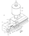
- FIG. 2 shows an example of a main part of the configuration of the transport device 80 and the oil supply device 90.
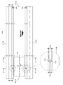
- FIG. 3 shows an example of a planar configuration of the transport device 80.
- FIG. 4 is a cross-sectional view of the transport device 80 shown in FIG. 3 cut along the line AA
- FIG. 5 shows a main part of the transport rail 10 on one side thereof.
- FIG. 6 shows a cross-sectional view of the transport device 80 shown in FIG. 3 cut along the line BB.
- the transport device 80 includes a transport rail (rail portion) 10, a chain 82, a lower key material 20, and an upper key material 30, as shown in FIGS.
- the transport rail 10 is composed of a pair of transport rails 10 and 10 disposed to face each other in the width direction of the printed circuit board 70, and the reflow apparatus main body 40. Are laid along the longitudinal direction (conveying direction H).
- a metal material such as aluminum is used for the transport rail 10.
- the pair of transport rails 10, 10 has a substantially U-shaped side surface with the opposite sides opened, and is provided above the lower rail 10 ⁇ / b> A provided below the chain 82 and the chain 82. And an upper rail 10B.
- a groove 12 for attaching the lower key material 20 is formed along the longitudinal direction of the transport rail 10.
- the width W ⁇ b> 1 of the groove 12 is selected to be substantially the same as the width W ⁇ b> 2 of the lower key material 20, and the depth D ⁇ b> 1 is the chain 82 when the chain 82 is placed on the upper surface of the lower key material 20.
- the depth is such that the lower end of the inner plate 82a is not in contact with the inner surface of the lower rail 10A.
- each lower key member 20 is fixed on the upstream side with respect to the conveyance path H1 of the printed circuit board 70, and the downstream side is a free end.
- a stopper 23 provided on the lower key material 20 is fixed by being inserted into the recess 11 of the groove 12. This is because when the lower key material 20 expands due to heat, the lower key material 20 is configured to expand in the transport direction side.
- the traveling direction of the chain 82 and the extending direction of the lower key member 20 coincide with each other, and the extension of the lower key member 20 is not stressed by the traveling of the chain 82. There will be no hindrance to driving.
- the chain 82 travels to cause vibration of the lower key material 20 with the fixed side as a starting point.
- the free end of the lower key material 20 is conveyed. Since the lower key material 20 is stretched in the direction opposite to the conveying direction due to the force that is lifted in the path and is hindered in the chain traveling or due to heat, the chain 82 is traveling in the conveying direction, so the lower key material 20
- the extension of the lower key material 20 causes stress on the lower key material and the lower key material 20 swells in the transport path, thereby obstructing the travel of the chain 82. May affect.
- a groove 14 for attaching the upper key material 30 is formed along the longitudinal direction of the transport rail 10.
- the width W3 of the groove portion 14 is selected to be slightly larger than the width W4 of the upper key member 30, and a gap A1 is formed between the groove portion 14 and the upper key member 30.
- the depth D2 of the groove portion 14 is selected so that a slight gap A2 is formed between the upper surface of the upper key material 30 and the groove upper surface of the groove portion 14 when the upper key material 30 is disposed on the bush 82c of the chain 82.
- the chain 82 has a pair of inner plates 82a, 82a, a pair of outer plates 82b, 82b, a bush 82c, a pin 82d, and a holding pin 82e.
- the two inner plates 82a and 82a are press-fitted through a bush 82c and coupled.
- the pin 82d is inserted inside the bush 82c, and outer plates 82b and 82b are press-fitted and coupled to both ends of the pin 82d and outside the inner plates 82a and 82a, respectively.
- the holding pin 82e holds the printed circuit board 70, and is provided so as to protrude from the plate surface of the outer plate 82b arranged on the transport rail 10 side facing each other.
- the printed circuit board 70 is placed on the holding pins 82e and conveyed along the conveying direction H.
- a pair of chains 82 is shown, but actually, a plurality of inner links having an inner plate 82a and a bush 82c and a plurality of outer links having an outer plate 82b and a pin 82d are alternately arranged. Concatenated and configured.
- the lower key member 20 is a long columnar body as shown in FIGS. 2 to 6, and is made of a metal material having excellent corrosion resistance and heat resistance, such as stainless steel (SUS).
- the lower key material 20 is fitted into the groove portion 12 so that the upper side of the lower key material 20 is exposed from the groove portion 12 and supports the bush 82c of the traveling chain 82 slidably on the upper surface portion thereof. Further, the lower key material 20 is fitted into the groove portion 12 without a gap, and is fixed to the groove portion 12 so as not to move in the transport direction H and a direction orthogonal thereto.
- the width W2 of the lower key member 20 is selected to be substantially the same as the length of the bush 82c in the longitudinal direction.
- the lower key material 20 constitutes an example of a support member.
- the lower key material 20 is divided into a plurality of key materials 20A, 20B, 20C, and 20D, and adjacent key materials 20A and 20B, key materials 20B and 20C, and key materials 20C and 20D.
- the stopper 23 is inserted into the recess 11 and is fitted into the groove 12 with a predetermined interval X1.
- the lower key material 20 may expand due to expansion based on the material of the lower key material 20, so that it is necessary to provide some clearance between the adjacent lower key materials 20. Therefore, the interval X1 is selected based on the expansion coefficient of the lower key material 20 and the like.
- FIG. 6 only the key materials 20B and 20C are shown for the sake of convenience as an example in which adjacent key materials are separated.
- a taper portion 22 that is inclined downward from the upper surface portion is provided at each of both ends in the longitudinal direction of the lower key material 20.
- a tapered portion 22a is provided at the end of the key member 20A on the carry-in port 40a side
- a tapered portion 22d is provided at the end of the key member 20D on the carry-out port 40b side.
- These tapered portions 22a and 22d function as guide portions for smoothly transporting the chain 82 inside and outside the tunnel of the reflow apparatus main body 40.
- a tapered portion 22b is provided at an end portion of the key material 20B facing the key material 20C
- a tapered portion 22c is provided at an end portion of the key material 20C facing the key material 20B.
- the upper key material 30 is a long columnar body like the lower key material 20, and is made of a metal material having excellent corrosion resistance and heat resistance, such as stainless steel (SUS).
- the upper key member 30 is inserted into a space formed by the groove portion 14 and the chain 82, and is placed on the bush 82c of the chain 82 by its own weight.
- a gap A1 is provided between the circumferential surface of the upper key member 30 and the groove circumferential surface of the groove portion 14, and the upper surface of the upper key member 30 and the groove upper surface of the groove portion 14
- a gap A2 is provided between them, and the upper key member 30 is disposed in the groove portion 14 with play. That is, the upper key member 30 is disposed in the groove portion 14 so as to be movable up and down and left and right through the gaps A1 and A2.
- the upper key material 30 is divided into a plurality of key materials 30A, 30B, and 30C as shown in FIG. This is because the upper key member 30 is divided and smoothly attached to the groove portion 14.
- the plurality of key members 30A, 30B, and 30C are attached by sequentially inserting the lower key member 20 and the chain 82 into the space portion formed by the groove portion 14 and the chain 82. Therefore, a stopper 38 for preventing the previously inserted upper key material 30 (key material 30C) from dropping or jumping out from the carry-out port 40b side of the groove portion 14 is provided at the other end of the groove portion 14 on the carry-out port 40b side. Is provided.
- the upper key material 30 is composed of three, but the present invention is not limited to this.
- a taper portion 32 that is inclined from the lower surface portion toward the upper outside is provided at the end of the key material 30 ⁇ / b> A on the carry-in port 40 a side.
- the tapered portion 32 functions as a guide portion for ensuring a wide entrance of the chain 82 and smoothly transporting the chain 82 into the reflow apparatus main body 40.
- the end portion 30a of the upper key material 30 (key material 30A) on the carry-in port 40a side is a distance X2 from the end portion 20a on the carry-in port 40a side of the lower key material 20 (key material 20A). It is provided at a position shifted to the downstream side in the transport direction H. This is because, when the end portion 20a of the key material 20A and the end portion 30a of the key material 30A are set at the same position, the entrance between the key material 20A and the key material 30A becomes narrow, so the carry-in port 40a.
- FIG. 7 and FIG. 3 are cross-sectional views taken along the line CC of the oil supply device 90 and the conveying device 80 shown in FIG. 7, and FIG. FIG. 9 shows an operation example of the upper key member 30 that moves up and down by the vibration of the chain 82.
- FIG. 7 shows an example in which the oil supply device 90 is installed only on one transport rail 10 for convenience.
- the fueling device 90 is installed above the upper rail 10 ⁇ / b> B and at the end of the upper rail 10 ⁇ / b> B on the side of the carry-in port 40 a, via the upper key material 30. Then, lubricating oil is supplied to the chain 82.
- the oil supply device 90 is installed on each of the two transport rails 10. Here, the oil supply device 90 is installed at the end of the carry-in entrance 40a of the transport rail 10 because the furnace is in a high temperature state during operation of the reflow device 100, and the lubricating oil supplied during the running of the chain 82 volatilizes. This is because it is necessary to supply lubricating oil to the chain 82 before the chain 82 travels in the furnace.
- the oil supply device 90 includes a container 92, a pipe 94, and a nozzle 96.
- the container 92 has a cylindrical shape with its upper end and lower end closed, and a predetermined amount of lubricating oil for stabilizing the running of the chain 82 is accommodated therein.
- One end of the pipe 94 communicates with the lower end portion of the container 92 and the other end communicates with the upper end portion of the nozzle 96, and is attached to the upper surface portion of the upper rail 10 ⁇ / b> B via the attachment metal plate 110.
- the nozzle 96 is provided immediately above a later-described oil supply hole 16 of the upper rail 10 ⁇ / b> B, and a tip portion thereof is provided slightly apart from the oil supply hole 16.
- the inner diameter of the nozzle 96 is selected to be substantially the same as the hole diameter of the oil supply hole 16.
- the nozzle 96 drops the lubricating oil supplied from the container 92 onto the upper surface portion 30d of the upper key member 30 through the oil supply hole 16 of the upper rail 10B (see FIG. 8).
- the upper rail 10B immediately below the nozzle 96 of the oil supply device 90 is provided with an oil supply hole 16 having a circular shape in plan view, as shown in FIGS.
- the oil supply hole 16 penetrates in a direction (thickness direction) orthogonal to the longitudinal direction of the upper rail 10B, and its lower end side communicates with a groove portion 14 formed in the upper rail 10B (see FIGS. 5 and 8).
- Lubricating oil from the device 90 is dropped on the upper key member 30 disposed in the groove portion 14.
- the hole diameter W5 of the oil supply hole 16 is selected to be slightly larger than the width W4 of the upper key member 30 so that the lubricating oil from the oil supply device 90 can be dripped reliably and smoothly. It has become.
- the upper key member 30 is arranged in the groove portion 14 so that the upper portion thereof enters the oil supply hole 16, and the lubricating oil supplied from the oil supply device 90 is supplied to the upper surface thereof.
- the lubricating oil received by the portion 30d functions as a transmission member that transmits the received lubricating oil to the bush 82c of the chain 82 on the lower surface side of the upper key material 30 through the side surface portion 30e from the upper surface portion 30d of the upper key material 30.
- the lower key member 20 functions as a holding member that receives the lubricating oil flowing down from the upper peripheral surface 82c1 of the bush 82c of the chain 82 at its upper surface portion 20d and stores the lubricating oil.
- the lubricating oil spread on the upper side of the bush 82c travels along the circumferential surface of the bush 82c by its own weight, flows down to the upper surface portion 20d of the lower key material 20, and is stored in the upper surface portion 20d. Thereby, the frictional resistance between the lower key material 20 and the chain 82 sliding on the upper surface portion 20d of the lower key material 20 can be reduced.
- the upper key material 30 is inserted into the space formed between the upper part of the chain 82 and the groove 14 of the transport rail 10 from the carry-in entrance 40a side. Since the upper key member 30 is divided into a plurality of pieces, these are sequentially inserted into the space portion. Since the stop portion 38 is provided on the carry-out port 40 b side of the groove portion 14, the upper key material 30 is pushed in until the previously inserted upper key material 30 is stopped by the stop portion 38. In this way, the transport device 80 can be configured.
- the lubricating oil is supplied to the chain 82 via the upper key member 30, compared to the case where the lubricating oil is supplied directly to the bush 82c of the chain 82, Lubricating oil can be uniformly applied to the bushing 82c of the chain 82. As a result, the frictional resistance between the chain 82 and the upper key material 30 can be reduced, the chain 82 can be driven stably, and the generation of metal powder due to the friction between the chain 82 and the upper key material 30 is prevented. Can be suppressed.
- lubricating oil can be applied to the entire chain 82 through a gap M formed by vertical vibrations when the chain 82 travels.
- the running of the chain 82 can be stabilized even with a small amount of lubricating oil.
- the nozzle 96 of the oil supply device 90 is arranged at a predetermined distance from the upper surface portion of the upper rail 10B, adhesion of the lubricating oil to the nozzle 96 can be prevented and poor lubrication of the lubricating oil can be avoided. Can do.
- Second Embodiment> In the second embodiment, a modification of the upper key member 30 will be described. Since the configuration of the other reflow apparatus 100 is the same as that of the first embodiment, common constituent elements are denoted by the same reference numerals, and detailed description thereof is omitted.
- FIG. 10 shows an example of the configuration of the upper key member 34 of the transport apparatus 80 according to the second embodiment of the present invention.
- the upper key member 34 has a truncated pyramid in the shape of the side surface located below the oil supply hole 16, and has a tapered portion 34 b continuous with the upper surface portion 34 c.
- the lubricating oil dropped from the oil supply device 90 can be supplied to the bush 82c of the chain 82 efficiently and smoothly.
- FIG. 11 shows an example of the configuration of another upper key member 36 of the transport apparatus 80 according to the second embodiment of the present invention.
- the upper key member 36 has a triangular shape at the side surface located below the oil supply hole 16, and has a tapered portion 36 a that is inclined from the upper part toward the lower part.
- the technical scope of the present invention is not limited to the above-described embodiment, and includes those in which various modifications are made to the above-described embodiment without departing from the spirit of the present invention.
- the lubricating oil is smoothly and stably supplied to the chain 82 using both the upper key material 30 and the lower key material 20, but the present invention is not limited to this.
- Lubricating oil may be supplied to the chain 82 using only the upper key member 30.
- the upper key member 30 is configured to be attached to the groove portion 14 via the gap M in order to stabilize the traveling of the chain 82, but is not limited to this configuration.
- the upper key member 30 may be fixed to the groove portion 14.
- the case where the hole diameter of the oil supply hole 16 and the inner diameter of the nozzle 96 are selected to be substantially the same has been described.
- FIGS. For example, as shown in FIG. 12, the opening 17 on the upper key member 30 side is smaller than the opening on the nozzle 96 side, as shown in FIG. A tapered opening 18 may be formed.
- the lubricating oil supplied from the nozzle 96 of the oil supply device 90 can be prevented from adhering to the upper surface of the upper rail 10B, and the lubricating oil can be reliably supplied to the chain 82 via the upper key member 30. it can.
- the present invention is applied to the oil supply device of the transfer device applied to the reflow device is described as an example, but the present invention can also be applied to a flow type soldering device or a similar transfer device.
Landscapes
- Engineering & Computer Science (AREA)
- Mechanical Engineering (AREA)
- General Engineering & Computer Science (AREA)
- Electric Connection Of Electric Components To Printed Circuits (AREA)
Abstract
Description
<1.第1の実施の形態>
[リフロー装置の構成例]
まず、本発明の一実施形態に係るリフロー装置100の概略構成について説明する。図1は、リフロー装置100の構成の一例を示している。図1に示すように、リフロー装置100は、リフロー装置本体40と搬送装置80と給油装置90とヒータ50とファン60とモータ62とを備えている。リフロー装置本体40は、搬入口40aと搬出口40bとを有するトンネル状の匡体であって、搬入口40aから搬出口40bに至る搬送経路に沿って予備加熱ゾーンZ1と本加熱ゾーンZ2と冷却ゾーンZ3とを有している。
[搬送装置の構成例]
次に、搬送装置80の構成の一例について説明する。図2は、搬送装置80および給油装置90の構成の要部の一例を示している。図3は、搬送装置80の平面構成の一例を示している。図4は、図3に示す搬送装置80をA-A線に沿って切断した断面図であり、図5は、その一方側の搬送レール10の要部を示している。図6は、図3に示す搬送装置80をB-B線に沿って切断した断面図を示している。
図7、図3に示す給油装置90および搬送装置80のC-C線に沿った断面図を示し、図8はその要部を示している。図9は、チェーン82の振動により上下移動する上部キー材30の動作例を示している。なお、図7の構成において上記図4および図5に示した構成と同様の構成については説明を省略する。また、図7では便宜上一方の搬送レール10にのみ給油装置90を設置した例を示している。
次に、潤滑オイルをチェーン82に給油する場合の潤滑オイルの流れの一例について図7~図9を参照して説明する。図7および図8に示すように、給油装置90のノズル96から潤滑オイルが滴下されると、滴下された潤滑オイルは上部レール10Bの給油孔16を通過して上部キー材30の上面部30dに流れ落ちる。上部キー材30の上面部30dに流れ落ちた潤滑オイルは、上部キー材30の上面部30dから側面部30eを伝わってチェーン82のブッシュ82cの端部に給油される。
次に、搬送装置80の組み立ての一例について図2~図6を用いて説明する。まず、下部キー材20を上部レール10Bの溝部12の所定位置に嵌め込む。このとき、上述したように、隣接する下部キー材20,20同士は、所定の間隔X1を隔てて溝部14に嵌め込む。続けて、下部キー材20の上面部20dに、連結していない状態のチェーン82を下部キー材20をガイドとして取り付けた後に、4箇所のスプロケット86にチェーン82を張架させた状態でチェーン82を連結する。
第2の実施の形態では、上部キー材30の変形例について説明する。なお、その他のリフロー装置100の構成は、上記第1の実施の形態と同様であるため、共通の構成要素には同一の符号を付し、詳細な説明は省略する。
Claims (3)
- 搬送用チェーンと、
給油孔を有して前記チェーンの上方に設けられ、前記チェーンを前記基板の搬送方向に沿って走行させるレール部と、
前記レール部の上方に設けられ、前記レール部の前記給油孔を通過させて前記チェーンにオイルを給油する給油部と、
前記チェーンと前記レール部との間に設けられた伝達部材とを備え、
前記給油部は、前記給油部から滴下される前記オイルを前記伝達部材を介して前記チェーンに給油する
ことを特徴とする搬送装置の給油装置。 - 前記チェーンの下部を支持すると共に、前記給油部から前記チェーンに給油されて下方に流れ落ちる前記オイルを貯留する支持部材を備える
ことを特徴とする請求項1に記載の搬送装置の給油装置。 - 前記レール部は、前記伝達部材が配置される位置に溝部を有し、
前記伝達部材は、前記レール部の前記溝部と前記チェーンの上部との間に隙間を介して移動可能に配置された
ことを特徴とする請求項1または請求項2に記載の搬送装置の給油装置。
Priority Applications (4)
| Application Number | Priority Date | Filing Date | Title |
|---|---|---|---|
| CN201180036720.8A CN103025631B (zh) | 2010-11-19 | 2011-11-16 | 输送装置的供油装置 |
| EP11842277.3A EP2567913B1 (en) | 2010-11-19 | 2011-11-16 | Oil supply device for conveyance device |
| KR1020127027910A KR101223318B1 (ko) | 2010-11-19 | 2011-11-16 | 반송 장치의 급유 장치 |
| US13/696,250 US8651266B2 (en) | 2010-11-19 | 2011-11-16 | Oil supply device for conveyance device |
Applications Claiming Priority (2)
| Application Number | Priority Date | Filing Date | Title |
|---|---|---|---|
| JP2010258595A JP4993015B2 (ja) | 2010-11-19 | 2010-11-19 | 搬送装置の給油装置 |
| JP2010-258595 | 2010-11-19 |
Publications (1)
| Publication Number | Publication Date |
|---|---|
| WO2012067154A1 true WO2012067154A1 (ja) | 2012-05-24 |
Family
ID=46084077
Family Applications (1)
| Application Number | Title | Priority Date | Filing Date |
|---|---|---|---|
| PCT/JP2011/076425 Ceased WO2012067154A1 (ja) | 2010-11-19 | 2011-11-16 | 搬送装置の給油装置 |
Country Status (7)
| Country | Link |
|---|---|
| US (1) | US8651266B2 (ja) |
| EP (1) | EP2567913B1 (ja) |
| JP (1) | JP4993015B2 (ja) |
| KR (1) | KR101223318B1 (ja) |
| CN (1) | CN103025631B (ja) |
| MY (1) | MY165785A (ja) |
| WO (1) | WO2012067154A1 (ja) |
Families Citing this family (8)
| Publication number | Priority date | Publication date | Assignee | Title |
|---|---|---|---|---|
| KR101405371B1 (ko) | 2013-01-16 | 2014-06-13 | (주)제일이앤엠 | 컨베이어용 윤활유 자동공급장치 |
| CN104108582A (zh) * | 2013-04-16 | 2014-10-22 | 苏州工业园区中法环境技术有限公司 | 刮板机 |
| CN104181094A (zh) * | 2013-05-24 | 2014-12-03 | 深圳市海洋王照明工程有限公司 | 一种透明件耐油性能测试装置 |
| JP7229217B2 (ja) * | 2020-10-29 | 2023-02-27 | 株式会社タムラ製作所 | グリス供給ユニット及び搬送加熱装置 |
| JP2022145521A (ja) * | 2021-03-18 | 2022-10-04 | 株式会社タムラ製作所 | グリス供給ユニット及び搬送加熱装置 |
| CN217731752U (zh) * | 2021-03-18 | 2022-11-04 | 株式会社田村制作所 | 润滑脂供给单元和搬送加热装置 |
| GB2626542A (en) * | 2023-01-24 | 2024-07-31 | Performance Fluids Ltd | Nozzle |
| CN121044339B (zh) * | 2025-11-05 | 2026-03-03 | 山西华耀光电科技有限公司 | 一种视觉引导液晶显示屏模组上料机及其使用方法 |
Citations (6)
| Publication number | Priority date | Publication date | Assignee | Title |
|---|---|---|---|---|
| US2304571A (en) * | 1941-11-07 | 1942-12-08 | Joa Curt G Inc | Conveyer lubrication |
| JPS5440379U (ja) * | 1977-08-26 | 1979-03-17 | ||
| JPS57167636U (ja) * | 1981-04-17 | 1982-10-22 | ||
| US4964344A (en) * | 1989-04-28 | 1990-10-23 | Mid-West Conveyor Company, Inc. | Side link pusher dog with lubrication passage |
| JPH11157630A (ja) | 1997-11-21 | 1999-06-15 | Matsushita Electric Ind Co Ltd | 潤滑油自動給油装置 |
| JPH11222310A (ja) | 1998-02-09 | 1999-08-17 | Matsushita Electric Ind Co Ltd | リフロー炉のチェーン潤滑洗浄装置 |
Family Cites Families (12)
| Publication number | Priority date | Publication date | Assignee | Title |
|---|---|---|---|---|
| US3124237A (en) * | 1964-03-10 | schommer | ||
| US3023848A (en) * | 1959-05-01 | 1962-03-06 | Herbert J Osterman | Lubrication device for conveyor chains |
| DE2246061B1 (de) * | 1972-09-20 | 1973-10-18 | Roland Offsetmaschinenfabrik Faber & Schleicher Ag, 6050 Offenbach | Greiferwagen-Transportkettenpaar aa Bogen verarbeitenden Maschinen, insbesondere Offsetmaschinen |
| US5186280A (en) * | 1991-05-03 | 1993-02-16 | Mattcheck Donald L | High temperature oven conveyor chain lubrication system |
| JPH09156747A (ja) * | 1995-12-12 | 1997-06-17 | Tsubakimoto Chain Co | チェーン給油装置 |
| US6591968B2 (en) * | 2001-09-07 | 2003-07-15 | Apv Baker, Inc. A Division Of Apv North America, Inc. | Method and apparatus for conditioning feeder chains in commercial baking ovens |
| JP2003238062A (ja) | 2002-02-18 | 2003-08-27 | Mitsubishi Electric Building Techno Service Co Ltd | 乗客コンベヤーの伝動鎖用給油装置 |
| DE20210758U1 (de) | 2002-07-17 | 2002-11-28 | Lincoln Gmbh & Co Kg | Schmiereinrichtung |
| US7455170B2 (en) * | 2005-11-15 | 2008-11-25 | Xact Fluid Solutions Division Of Behnke Lubricants, Jax Usa | Conveyor chain lubrication system |
| JP2009161286A (ja) | 2007-12-28 | 2009-07-23 | Mitsubishi Electric Building Techno Service Co Ltd | 乗客コンベアのチェーン給油装置 |
| JP4700092B2 (ja) * | 2008-10-01 | 2011-06-15 | 株式会社椿本チエイン | 自動給油チェーン |
| CN201338853Y (zh) * | 2008-11-28 | 2009-11-04 | 天津钢铁有限公司 | 混取机斗轮传动链内孔润滑结构 |
-
2010
- 2010-11-19 JP JP2010258595A patent/JP4993015B2/ja active Active
-
2011
- 2011-11-16 US US13/696,250 patent/US8651266B2/en active Active
- 2011-11-16 CN CN201180036720.8A patent/CN103025631B/zh active Active
- 2011-11-16 EP EP11842277.3A patent/EP2567913B1/en active Active
- 2011-11-16 KR KR1020127027910A patent/KR101223318B1/ko active Active
- 2011-11-16 WO PCT/JP2011/076425 patent/WO2012067154A1/ja not_active Ceased
- 2011-11-16 MY MYPI2012005394A patent/MY165785A/en unknown
Patent Citations (6)
| Publication number | Priority date | Publication date | Assignee | Title |
|---|---|---|---|---|
| US2304571A (en) * | 1941-11-07 | 1942-12-08 | Joa Curt G Inc | Conveyer lubrication |
| JPS5440379U (ja) * | 1977-08-26 | 1979-03-17 | ||
| JPS57167636U (ja) * | 1981-04-17 | 1982-10-22 | ||
| US4964344A (en) * | 1989-04-28 | 1990-10-23 | Mid-West Conveyor Company, Inc. | Side link pusher dog with lubrication passage |
| JPH11157630A (ja) | 1997-11-21 | 1999-06-15 | Matsushita Electric Ind Co Ltd | 潤滑油自動給油装置 |
| JPH11222310A (ja) | 1998-02-09 | 1999-08-17 | Matsushita Electric Ind Co Ltd | リフロー炉のチェーン潤滑洗浄装置 |
Non-Patent Citations (1)
| Title |
|---|
| See also references of EP2567913A4 * |
Also Published As
| Publication number | Publication date |
|---|---|
| EP2567913A4 (en) | 2013-03-27 |
| US8651266B2 (en) | 2014-02-18 |
| JP2012106852A (ja) | 2012-06-07 |
| MY165785A (en) | 2018-04-25 |
| CN103025631A (zh) | 2013-04-03 |
| KR20120127545A (ko) | 2012-11-21 |
| EP2567913A1 (en) | 2013-03-13 |
| CN103025631B (zh) | 2014-08-20 |
| US20130126305A1 (en) | 2013-05-23 |
| JP4993015B2 (ja) | 2012-08-08 |
| KR101223318B1 (ko) | 2013-01-16 |
| EP2567913B1 (en) | 2014-01-22 |
Similar Documents
| Publication | Publication Date | Title |
|---|---|---|
| JP4993015B2 (ja) | 搬送装置の給油装置 | |
| CN106660152B (zh) | 波峰焊接喷嘴机器、波峰焊接喷嘴系统以及波峰焊接方法 | |
| JP5463129B2 (ja) | リフロー装置 | |
| CN102625596B (zh) | 焊接插件式元件于电路板的方法及焊接系统 | |
| JP5533650B2 (ja) | 自動はんだ付け装置 | |
| JP5299409B2 (ja) | 搬送装置 | |
| KR20160111498A (ko) | 웨이브 납땜기를 위한 강제 대류 예열기 및 관련 방법 | |
| JP2012106273A5 (ja) | ||
| JP7229217B2 (ja) | グリス供給ユニット及び搬送加熱装置 | |
| JP3577203B2 (ja) | 潤滑油自動給油装置 | |
| JP7550253B2 (ja) | 搬送加熱装置 | |
| CN217731752U (zh) | 润滑脂供给单元和搬送加热装置 | |
| JP2020136626A (ja) | はんだ付け装置及びはんだ付け装置にパッキンを固定する方法 | |
| JP2003179342A (ja) | リフロー炉 | |
| KR100776262B1 (ko) | 자동납땜장치 | |
| JP4784796B2 (ja) | 搬送コンベアを有する機器における被搬送物の固定用治具 | |
| JP2022145521A (ja) | グリス供給ユニット及び搬送加熱装置 | |
| JP2012079831A (ja) | リフロー装置及びこれを用いた半導体実装基板の製造方法 | |
| JP2008226980A (ja) | リフロー装置 | |
| JP2005197302A (ja) | 搬送装置 | |
| JPH04109695A (ja) | プリント基板のリフローはんだ付け方法およびその装置 | |
| JP3813027B2 (ja) | はんだ付け装置 | |
| JP2005294671A (ja) | ハンダ付けされたプリント基板の冷却装置 | |
| JP2009009972A (ja) | リフロー半田付け装置 | |
| JP2007194319A (ja) | はんだ付け用マスクおよびはんだ付け方法 |
Legal Events
| Date | Code | Title | Description |
|---|---|---|---|
| WWE | Wipo information: entry into national phase |
Ref document number: 201180036720.8 Country of ref document: CN |
|
| 121 | Ep: the epo has been informed by wipo that ep was designated in this application |
Ref document number: 11842277 Country of ref document: EP Kind code of ref document: A1 |
|
| ENP | Entry into the national phase |
Ref document number: 20127027910 Country of ref document: KR Kind code of ref document: A |
|
| WWE | Wipo information: entry into national phase |
Ref document number: 2011842277 Country of ref document: EP |
|
| WWE | Wipo information: entry into national phase |
Ref document number: 13696250 Country of ref document: US |
|
| WWE | Wipo information: entry into national phase |
Ref document number: 1201006786 Country of ref document: TH |
|
| NENP | Non-entry into the national phase |
Ref country code: DE |