WO2012074094A1 - Système de batterie secondaire, et véhicule électrique - Google Patents
Système de batterie secondaire, et véhicule électrique Download PDFInfo
- Publication number
- WO2012074094A1 WO2012074094A1 PCT/JP2011/077919 JP2011077919W WO2012074094A1 WO 2012074094 A1 WO2012074094 A1 WO 2012074094A1 JP 2011077919 W JP2011077919 W JP 2011077919W WO 2012074094 A1 WO2012074094 A1 WO 2012074094A1
- Authority
- WO
- WIPO (PCT)
- Prior art keywords
- battery
- charging
- converter
- operating
- batteries
- Prior art date
- Legal status (The legal status is an assumption and is not a legal conclusion. Google has not performed a legal analysis and makes no representation as to the accuracy of the status listed.)
- Ceased
Links
Images


Classifications
-
- B—PERFORMING OPERATIONS; TRANSPORTING
- B60—VEHICLES IN GENERAL
- B60L—PROPULSION OF ELECTRICALLY-PROPELLED VEHICLES; SUPPLYING ELECTRIC POWER FOR AUXILIARY EQUIPMENT OF ELECTRICALLY-PROPELLED VEHICLES; ELECTRODYNAMIC BRAKE SYSTEMS FOR VEHICLES IN GENERAL; MAGNETIC SUSPENSION OR LEVITATION FOR VEHICLES; MONITORING OPERATING VARIABLES OF ELECTRICALLY-PROPELLED VEHICLES; ELECTRIC SAFETY DEVICES FOR ELECTRICALLY-PROPELLED VEHICLES
- B60L58/00—Methods or circuit arrangements for monitoring or controlling batteries or fuel cells, specially adapted for electric vehicles
- B60L58/10—Methods or circuit arrangements for monitoring or controlling batteries or fuel cells, specially adapted for electric vehicles for monitoring or controlling batteries
- B60L58/18—Methods or circuit arrangements for monitoring or controlling batteries or fuel cells, specially adapted for electric vehicles for monitoring or controlling batteries of two or more battery modules
- B60L58/21—Methods or circuit arrangements for monitoring or controlling batteries or fuel cells, specially adapted for electric vehicles for monitoring or controlling batteries of two or more battery modules having the same nominal voltage
-
- B—PERFORMING OPERATIONS; TRANSPORTING
- B60—VEHICLES IN GENERAL
- B60L—PROPULSION OF ELECTRICALLY-PROPELLED VEHICLES; SUPPLYING ELECTRIC POWER FOR AUXILIARY EQUIPMENT OF ELECTRICALLY-PROPELLED VEHICLES; ELECTRODYNAMIC BRAKE SYSTEMS FOR VEHICLES IN GENERAL; MAGNETIC SUSPENSION OR LEVITATION FOR VEHICLES; MONITORING OPERATING VARIABLES OF ELECTRICALLY-PROPELLED VEHICLES; ELECTRIC SAFETY DEVICES FOR ELECTRICALLY-PROPELLED VEHICLES
- B60L50/00—Electric propulsion with power supplied within the vehicle
- B60L50/50—Electric propulsion with power supplied within the vehicle using propulsion power supplied by batteries or fuel cells
- B60L50/52—Electric propulsion with power supplied within the vehicle using propulsion power supplied by batteries or fuel cells characterised by DC-motors
-
- B—PERFORMING OPERATIONS; TRANSPORTING
- B60—VEHICLES IN GENERAL
- B60L—PROPULSION OF ELECTRICALLY-PROPELLED VEHICLES; SUPPLYING ELECTRIC POWER FOR AUXILIARY EQUIPMENT OF ELECTRICALLY-PROPELLED VEHICLES; ELECTRODYNAMIC BRAKE SYSTEMS FOR VEHICLES IN GENERAL; MAGNETIC SUSPENSION OR LEVITATION FOR VEHICLES; MONITORING OPERATING VARIABLES OF ELECTRICALLY-PROPELLED VEHICLES; ELECTRIC SAFETY DEVICES FOR ELECTRICALLY-PROPELLED VEHICLES
- B60L53/00—Methods of charging batteries, specially adapted for electric vehicles; Charging stations or on-board charging equipment therefor; Exchange of energy storage elements in electric vehicles
- B60L53/80—Exchanging energy storage elements, e.g. removable batteries
-
- B—PERFORMING OPERATIONS; TRANSPORTING
- B60—VEHICLES IN GENERAL
- B60L—PROPULSION OF ELECTRICALLY-PROPELLED VEHICLES; SUPPLYING ELECTRIC POWER FOR AUXILIARY EQUIPMENT OF ELECTRICALLY-PROPELLED VEHICLES; ELECTRODYNAMIC BRAKE SYSTEMS FOR VEHICLES IN GENERAL; MAGNETIC SUSPENSION OR LEVITATION FOR VEHICLES; MONITORING OPERATING VARIABLES OF ELECTRICALLY-PROPELLED VEHICLES; ELECTRIC SAFETY DEVICES FOR ELECTRICALLY-PROPELLED VEHICLES
- B60L58/00—Methods or circuit arrangements for monitoring or controlling batteries or fuel cells, specially adapted for electric vehicles
- B60L58/10—Methods or circuit arrangements for monitoring or controlling batteries or fuel cells, specially adapted for electric vehicles for monitoring or controlling batteries
- B60L58/18—Methods or circuit arrangements for monitoring or controlling batteries or fuel cells, specially adapted for electric vehicles for monitoring or controlling batteries of two or more battery modules
-
- Y—GENERAL TAGGING OF NEW TECHNOLOGICAL DEVELOPMENTS; GENERAL TAGGING OF CROSS-SECTIONAL TECHNOLOGIES SPANNING OVER SEVERAL SECTIONS OF THE IPC; TECHNICAL SUBJECTS COVERED BY FORMER USPC CROSS-REFERENCE ART COLLECTIONS [XRACs] AND DIGESTS
- Y02—TECHNOLOGIES OR APPLICATIONS FOR MITIGATION OR ADAPTATION AGAINST CLIMATE CHANGE
- Y02T—CLIMATE CHANGE MITIGATION TECHNOLOGIES RELATED TO TRANSPORTATION
- Y02T10/00—Road transport of goods or passengers
- Y02T10/60—Other road transportation technologies with climate change mitigation effect
- Y02T10/70—Energy storage systems for electromobility, e.g. batteries
-
- Y—GENERAL TAGGING OF NEW TECHNOLOGICAL DEVELOPMENTS; GENERAL TAGGING OF CROSS-SECTIONAL TECHNOLOGIES SPANNING OVER SEVERAL SECTIONS OF THE IPC; TECHNICAL SUBJECTS COVERED BY FORMER USPC CROSS-REFERENCE ART COLLECTIONS [XRACs] AND DIGESTS
- Y02—TECHNOLOGIES OR APPLICATIONS FOR MITIGATION OR ADAPTATION AGAINST CLIMATE CHANGE
- Y02T—CLIMATE CHANGE MITIGATION TECHNOLOGIES RELATED TO TRANSPORTATION
- Y02T10/00—Road transport of goods or passengers
- Y02T10/60—Other road transportation technologies with climate change mitigation effect
- Y02T10/7072—Electromobility specific charging systems or methods for batteries, ultracapacitors, supercapacitors or double-layer capacitors
Definitions
- the present invention relates to a secondary battery system and an electric vehicle including the same.
- a secondary battery system includes a plurality of charging batteries connected in parallel to each other, a converter that adjusts and outputs a voltage input from the charging battery, and is charged by an output of the converter to a load.
- An operating battery for supplying electric power.
- a charging battery and an operating battery are prepared, and a voltage is adjusted by a converter from a plurality of charging batteries connected in parallel and output to the operating battery, and the operating battery is charged. Power is supplied from the operating battery to a load such as a motor. Thereby, it becomes possible to equalize the lifetime of the some battery (charge battery) connected in parallel.
- switching means for selectively connecting any of the charging batteries to the converter may be provided between the converter and the charging battery.
- one of the charging batteries can be selectively connected to the converter by the switching means according to the charged amount of each charging battery.
- the converter may repeatedly charge and stop the operating battery by a predetermined amount while the remaining amount of the operating battery becomes a predetermined level or less.
- the operating battery when the operating battery becomes less than a predetermined predetermined remaining amount, when charging the operating battery from the charging battery to the operating battery by the converter, the operating battery is charged by a predetermined amount instead of being fully charged. Repeat the charging process. Thereby, it becomes possible to extend the life of the battery for operation compared with the case where full charge is repeated from discharge.
- the switching means may perform switching based on a detected value of a voltage of the charging battery and / or a charging current of the operating battery.
- the voltage of the charging battery and the charging current of the operating battery are detected, and the switching means is switched based on the detected voltage. Thereby, it becomes possible to make the lifetimes of a plurality of charging batteries uniform.
- the electric vehicle of the present invention includes any one of the above secondary battery systems.
- the effect of any of the above secondary battery systems can be imparted to the electric vehicle.
- the electric vehicle of the present invention may include a driving vehicle provided with the operating battery and a towing vehicle provided with the charging battery and towed by the driving vehicle.
- the towing vehicle provided with the charging battery is towed by the driving vehicle, so that the cost of vehicle development can be suppressed. Further, by replacing the entire towing vehicle, it is possible to easily and efficiently replace the charging battery in a short time. Furthermore, a towing vehicle equipped with a rechargeable battery can be used alone as a power source for disasters, event venues, and construction.
- the battery for operation and the battery for operation are prepared, and the battery for operation is prepared by adjusting the voltage with a converter from a plurality of batteries connected in parallel.
- a converter from a plurality of batteries connected in parallel.
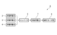
- the secondary battery system A of the present embodiment includes a plurality of charging batteries 2, 3, 4, a converter (DC-DC converter) 5, and an operating battery 7, as shown in FIG.
- the plurality of charging batteries 2, 3, 4 are connected in parallel to each other.
- Converter 5 adjusts and outputs the voltage input from charging batteries 2-4.
- the operating battery 7 is charged by the output of the converter 5 and supplies power to a load 6 such as a motor.
- the amount of power of each of the plurality of charging batteries 2 to 4 and the operating battery 7 is, for example, 15 kWh.
- switching means for selectively connecting any of the charging batteries 2 to 4 to the converter 5 between the converter 5 and the charging batteries 2 to 4.
- a switching unit 8.
- the secondary battery system A includes a first voltage detecting means 9 for detecting the voltages of the charging batteries 2 to 4, a second voltage detecting means 10 for detecting the voltage of the operating battery 7, and the operating battery 7.
- Current detecting means 11 for detecting the charging current and a charger function unit 12.
- the charger function unit 12 includes a converter 5, first voltage detection means 9, second voltage detection means 10, and current detection means 11.
- detection values by the first voltage detection means 9, the second voltage detection means 10 and the current detection means 11 are sent to the control means 13.
- the control means 13 controls the switching means 8 and the converter 5 based on the voltage values of the charging batteries 2 to 4 and / or the detected value of the charging current of the operating battery 7.
- charging batteries 2 to 4 and an operating battery 7 are prepared as the battery 1, and a plurality of charging batteries 2 to 2 connected in parallel are prepared.
- the voltage is adjusted from 4 to the converter 5 and output to the operating battery 7, and the operating battery 7 is charged.
- power is not supplied from the plurality of batteries 1 connected in parallel to the load 6 such as a motor as in the prior art, but power is supplied from the operating battery 7 to the load 6.
- any one of the charging batteries 2 to 4 is selectively connected to the converter 5 by the switching means 8 from the plurality of charging batteries 2 to 4 according to the charged amount of each of the charging batteries 2 to 4.
- the switching means 8 sequentially connects the charging batteries 2 to 4 to the converter 5 according to the amount of charge of each charging battery 2 to 4, and uses the second charging battery 3 at the earliest. Charging is performed in the middle of using the third charging battery 4 at the latest. Since the repeated use life of the batteries 2 to 4 becomes shorter as the power consumption increases, the charging batteries 2 to 4 are selectively used by the switching means 8 in this way, whereby each charging battery 2 The remaining life of ⁇ 4 can be made uniform.
- the charging battery 2 having a long remaining life is combined. Reduce the remaining amount of switching. That is, for example, it is assumed that there are three charging batteries 2 to 4 and the remaining life is longer in the order of the charging battery 2, the charging battery 3, and the charging battery 4.
- the charging battery 2 with the longest remaining life reaches 15% and the charging battery 3 with the second longest remaining life Is switched by the switching means 8 so that the charging battery 4 having the shortest remaining life is used up to the remaining amount of 20% and the remaining amount of 25%.
- the remaining life of each of the charging batteries 2 to 4 can be made more uniform.
- the output voltage of the charging batteries 2 to 4 selected by the switching means 8 is detected by the first voltage detecting means 9, and the voltage of the operating battery 7 is detected by the second voltage detecting means 10. Then, the detection results of the first and second voltage detection means 9 and 10 are sent to the control means 13, and the converter 5 is suitable for charging the working battery 7 by the operation command from the control means 13. The voltage is converted and output to the operating battery 7. For example, when the voltage of the operating battery 7 is higher than that of the charging batteries 2 to 4, the converter 5 boosts the input voltage from the charging batteries 2 to 4 and outputs the boosted voltage to the operating battery 7 for operation. The battery 7 can be charged.
- the converter 5 is controlled so that the remaining amount of the operating battery 7 becomes less than a predetermined value and the operating battery 7 is repeatedly charged and stopped by a predetermined amount. Then, if the repetitive charging is repeated as described above, the life of the working battery 7 is extended as compared with the case where the full charge is repeated from the discharge as shown in FIG.
- the secondary battery system A is provided in an electric vehicle (electric vehicle) B such as an electric bus as shown in FIG.
- the electric automobile B includes a base vehicle (driving vehicle) B1 and a battery vehicle (towing vehicle) B2. Further, an operating battery 7 is mounted on the base vehicle B1, and a plurality of charging batteries 2 to 4 are mounted on the battery vehicle B2.
- the electric vehicle B of the present embodiment as shown in FIG. 3, only the operation battery 7 is mounted on the base vehicle B1, and the battery vehicle B2 provided with the charging batteries 2 to 4 is used as the base vehicle B1. Tow. For this reason, a small capacity battery vehicle can be used for the base vehicle B1. Further, the charging batteries 2 to 4 need only be mounted and stored in the battery vehicle B2, and an automatic warehouse or the like becomes unnecessary. Further, the batteries 2 to 4 can be easily replaced by detaching the battery vehicle B2 from the base vehicle B1 in the same manner as the trailer.
- the charging batteries 2 to 4 and the operating battery 7 are prepared as the battery 1, and the converter 5 is connected to the plurality of charging batteries 2 to 4 connected in parallel.
- the voltage is adjusted and output to the operating battery 7, the operating battery 7 is charged, and electric power is supplied from the operating battery 7 to the load 6 such as a motor. This makes it possible to equalize the lifetimes of the plurality of batteries (charging batteries) 2 to 4 connected in parallel.
- any one of the charging batteries 2 to 4 can be selectively connected from the plurality of charging batteries 2 to 4 to the converter 5 by the switching means 8 according to the amount of charge of each of the charging batteries 2 to 4. .
- the life of a plurality of batteries (charging batteries) 2 to 4 can be reliably ensured. It becomes possible to make uniform.
- the operating battery 7 becomes less than a predetermined remaining battery level and is charged from the charging batteries 2 to 4 to the operating battery 7 by the converter 5, the operating battery 7 is not fully charged but is charged to the operating battery 7. It is charged repeatedly by a predetermined amount, and detailed charging is repeated. As a result, it is possible to extend the life of the operating battery 7 as compared with a case where full charge is repeated from discharge.
- the voltage of the charging batteries 2 to 4 and the charging current of the operating battery 7 are detected, and the switching means 8 is switched based on the detected voltage, so that a plurality of charging batteries 2 to 4 can be reliably connected.
- the service life can be made uniform.
- the electric vehicle B of the present embodiment only the operation battery 7 is mounted on the base vehicle (driving vehicle) B1, and the battery vehicle (towing vehicle) B2 provided with the charging batteries 2 to 4 is the base vehicle B1. Tow. Thereby, it becomes possible to hold down the cost of vehicle development. Further, by replacing the battery vehicle B2 together, it becomes possible to replace the charging batteries 2 to 4 easily and efficiently in a short time. Furthermore, the battery vehicle B2 equipped with the charging batteries 2 to 4 can be used alone as a power source for disasters, event venues, construction, and the like.
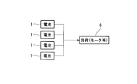
- the secondary battery system A may be configured without the switching means 8 as shown in FIG. In this case as well, it is possible to make the life of the plurality of charging batteries 2 to 4 uniform as in the present embodiment.
- the present invention includes a plurality of charging batteries connected in parallel to each other, a converter that adjusts and outputs a voltage input from the charging battery, and an operation that is charged by the output of the converter and supplies power to a load.
- the present invention relates to a secondary battery system including a battery for use. According to the present invention, the life of a plurality of batteries (charging batteries) connected in parallel can be made uniform.
Landscapes
- Engineering & Computer Science (AREA)
- Power Engineering (AREA)
- Transportation (AREA)
- Mechanical Engineering (AREA)
- Life Sciences & Earth Sciences (AREA)
- Sustainable Development (AREA)
- Sustainable Energy (AREA)
- Charge And Discharge Circuits For Batteries Or The Like (AREA)
- Electric Propulsion And Braking For Vehicles (AREA)
- Secondary Cells (AREA)
Abstract
Le système de batterie secondaire de l'invention est équipé : d'une pluralité de batteries pour la charge (2, 3, 4) connectées les unes aux autres en parallèle; d'un convertisseur (5) qui régule et émet en sortie une tension fournie en entrée par des batteries pour la charge (2, 3, 4); et d'une batterie pour le fonctionnement (7) chargée au moyen de l'entrée fournie par le convertisseur (5), et qui alimente une charge (6) en puissance électrique.
Applications Claiming Priority (2)
| Application Number | Priority Date | Filing Date | Title |
|---|---|---|---|
| JP2010-270515 | 2010-12-03 | ||
| JP2010270515A JP2012120403A (ja) | 2010-12-03 | 2010-12-03 | 二次電池システム及び電動車両 |
Publications (1)
| Publication Number | Publication Date |
|---|---|
| WO2012074094A1 true WO2012074094A1 (fr) | 2012-06-07 |
Family
ID=46172016
Family Applications (1)
| Application Number | Title | Priority Date | Filing Date |
|---|---|---|---|
| PCT/JP2011/077919 Ceased WO2012074094A1 (fr) | 2010-12-03 | 2011-12-02 | Système de batterie secondaire, et véhicule électrique |
Country Status (2)
| Country | Link |
|---|---|
| JP (1) | JP2012120403A (fr) |
| WO (1) | WO2012074094A1 (fr) |
Cited By (3)
| Publication number | Priority date | Publication date | Assignee | Title |
|---|---|---|---|---|
| CN106585409A (zh) * | 2016-12-16 | 2017-04-26 | 南京哈恩科技有限公司 | 电池管理方法以及应用其的电动车和冷链系统 |
| KR20190006526A (ko) * | 2016-05-12 | 2019-01-18 | 리텔퓨즈 인코퍼레이티드 | 다중 전력원을 사용하기 위한 릴레이 |
| GB2595360A (en) * | 2020-04-24 | 2021-11-24 | Ocado Innovation Ltd | Apparatus and method for charging a load handling device on a grid |
Families Citing this family (1)
| Publication number | Priority date | Publication date | Assignee | Title |
|---|---|---|---|---|
| KR102799961B1 (ko) | 2021-05-14 | 2025-04-23 | 주식회사 엘지에너지솔루션 | Dc-dc 변환을 수행하는 컨버터 및 이를 제어하는 방법 |
Citations (4)
| Publication number | Priority date | Publication date | Assignee | Title |
|---|---|---|---|---|
| JPH03123576U (fr) * | 1990-03-26 | 1991-12-16 | ||
| JP2004134145A (ja) * | 2002-10-08 | 2004-04-30 | Ricoh Co Ltd | 電源装置及びこの電源装置を備えたデジタルカメラ |
| JP2007057433A (ja) * | 2005-08-25 | 2007-03-08 | Fuji Heavy Ind Ltd | 蓄電デバイスの劣化状態推定システム |
| JP2010111381A (ja) * | 2008-10-08 | 2010-05-20 | Toyota Auto Body Co Ltd | 搬送機 |
Family Cites Families (2)
| Publication number | Priority date | Publication date | Assignee | Title |
|---|---|---|---|---|
| JP3469228B2 (ja) * | 2002-02-13 | 2003-11-25 | 三菱重工業株式会社 | 蓄電装置の充放電制御装置及び充放電制御方法並びに電力貯蔵システム |
| JP3123576U (ja) * | 2006-05-11 | 2006-07-20 | 伊藤 昇 | Evステーションシステム |
-
2010
- 2010-12-03 JP JP2010270515A patent/JP2012120403A/ja active Pending
-
2011
- 2011-12-02 WO PCT/JP2011/077919 patent/WO2012074094A1/fr not_active Ceased
Patent Citations (4)
| Publication number | Priority date | Publication date | Assignee | Title |
|---|---|---|---|---|
| JPH03123576U (fr) * | 1990-03-26 | 1991-12-16 | ||
| JP2004134145A (ja) * | 2002-10-08 | 2004-04-30 | Ricoh Co Ltd | 電源装置及びこの電源装置を備えたデジタルカメラ |
| JP2007057433A (ja) * | 2005-08-25 | 2007-03-08 | Fuji Heavy Ind Ltd | 蓄電デバイスの劣化状態推定システム |
| JP2010111381A (ja) * | 2008-10-08 | 2010-05-20 | Toyota Auto Body Co Ltd | 搬送機 |
Cited By (8)
| Publication number | Priority date | Publication date | Assignee | Title |
|---|---|---|---|---|
| KR20190006526A (ko) * | 2016-05-12 | 2019-01-18 | 리텔퓨즈 인코퍼레이티드 | 다중 전력원을 사용하기 위한 릴레이 |
| CN109478796A (zh) * | 2016-05-12 | 2019-03-15 | 力特有限公司 | 与多个电源一起使用的继电器 |
| JP2019517233A (ja) * | 2016-05-12 | 2019-06-20 | リテルヒューズ・インク | 複数の電源と共に使用するためのリレー |
| KR102246813B1 (ko) * | 2016-05-12 | 2021-04-30 | 리텔퓨즈 인코퍼레이티드 | 다중 전력원을 사용하기 위한 릴레이 |
| CN109478796B (zh) * | 2016-05-12 | 2022-09-13 | 力特有限公司 | 与多个电源一起使用的继电器 |
| CN106585409A (zh) * | 2016-12-16 | 2017-04-26 | 南京哈恩科技有限公司 | 电池管理方法以及应用其的电动车和冷链系统 |
| GB2595360A (en) * | 2020-04-24 | 2021-11-24 | Ocado Innovation Ltd | Apparatus and method for charging a load handling device on a grid |
| GB2595360B (en) * | 2020-04-24 | 2023-04-19 | Ocado Innovation Ltd | Apparatus and method for charging a load handling device on a grid |
Also Published As
| Publication number | Publication date |
|---|---|
| JP2012120403A (ja) | 2012-06-21 |
Similar Documents
| Publication | Publication Date | Title |
|---|---|---|
| US9174547B2 (en) | Electric vehicle and charging control method for auxiliary battery thereof | |
| US10059217B2 (en) | System and method for controlling battery switching serial/parallel connection of battery modules due to accelerator operation | |
| KR101680526B1 (ko) | 배터리 제어 장치 및 방법 | |
| JP5605320B2 (ja) | 車両用電源装置 | |
| CN102574470B (zh) | 车辆的充电系统及包含该车辆的充电系统的电动车辆 | |
| JP5960580B2 (ja) | 電気自動車の電源供給システム及びその制御方法 | |
| JP5333005B2 (ja) | 車両用電源装置 | |
| US20120319657A1 (en) | Battery management system | |
| CN110382282B (zh) | 车辆电源装置 | |
| JP5487817B2 (ja) | 補助バッテリ給電システムおよび補助バッテリ給電方法 | |
| CN104553842B (zh) | 用于控制燃料电池车辆的方法和系统 | |
| CN103683369B (zh) | 充放电系统 | |
| US20200195033A1 (en) | Battery charge control apparatus for vehicle and method of controlling battery charging of vehicle | |
| KR102386233B1 (ko) | 재활용 배터리를 이용한 에너지 저장 시스템 | |
| KR20130120229A (ko) | 전기 자동차의 충전 방법 | |
| JP7006572B2 (ja) | 車両用充電制御システム | |
| CN102529733A (zh) | 动力电池系统及控制方法 | |
| WO2012074094A1 (fr) | Système de batterie secondaire, et véhicule électrique | |
| KR20190095992A (ko) | 철도차량의 배터리 관리 시스템 및 방법 | |
| JP2019221038A (ja) | 電源装置 | |
| JP2015052513A (ja) | 電気自動車 | |
| JP6034734B2 (ja) | 電力システム | |
| JP2018093633A (ja) | 車載電源装置 | |
| KR20120031609A (ko) | 차량의 회생전력 손실 방지 방법 | |
| JP5131977B2 (ja) | 蓄電装置の制御装置 |
Legal Events
| Date | Code | Title | Description |
|---|---|---|---|
| 121 | Ep: the epo has been informed by wipo that ep was designated in this application |
Ref document number: 11844028 Country of ref document: EP Kind code of ref document: A1 |
|
| NENP | Non-entry into the national phase |
Ref country code: DE |
|
| 122 | Ep: pct application non-entry in european phase |
Ref document number: 11844028 Country of ref document: EP Kind code of ref document: A1 |