WO2012081599A1 - プローブ - Google Patents
プローブ Download PDFInfo
- Publication number
- WO2012081599A1 WO2012081599A1 PCT/JP2011/078865 JP2011078865W WO2012081599A1 WO 2012081599 A1 WO2012081599 A1 WO 2012081599A1 JP 2011078865 W JP2011078865 W JP 2011078865W WO 2012081599 A1 WO2012081599 A1 WO 2012081599A1
- Authority
- WO
- WIPO (PCT)
- Prior art keywords
- optical fiber
- optical axis
- light
- lens
- light receiving
- Prior art date
- Legal status (The legal status is an assumption and is not a legal conclusion. Google has not performed a legal analysis and makes no representation as to the accuracy of the status listed.)
- Ceased
Links
Images




Classifications
-
- A—HUMAN NECESSITIES
- A61—MEDICAL OR VETERINARY SCIENCE; HYGIENE
- A61B—DIAGNOSIS; SURGERY; IDENTIFICATION
- A61B5/00—Measuring for diagnostic purposes; Identification of persons
- A61B5/0059—Measuring for diagnostic purposes; Identification of persons using light, e.g. diagnosis by transillumination, diascopy, fluorescence
- A61B5/0082—Measuring for diagnostic purposes; Identification of persons using light, e.g. diagnosis by transillumination, diascopy, fluorescence adapted for particular medical purposes
- A61B5/0084—Measuring for diagnostic purposes; Identification of persons using light, e.g. diagnosis by transillumination, diascopy, fluorescence adapted for particular medical purposes for introduction into the body, e.g. by catheters
-
- A—HUMAN NECESSITIES
- A61—MEDICAL OR VETERINARY SCIENCE; HYGIENE
- A61B—DIAGNOSIS; SURGERY; IDENTIFICATION
- A61B5/00—Measuring for diagnostic purposes; Identification of persons
- A61B5/0059—Measuring for diagnostic purposes; Identification of persons using light, e.g. diagnosis by transillumination, diascopy, fluorescence
-
- A—HUMAN NECESSITIES
- A61—MEDICAL OR VETERINARY SCIENCE; HYGIENE
- A61B—DIAGNOSIS; SURGERY; IDENTIFICATION
- A61B1/00—Instruments for performing medical examinations of the interior of cavities or tubes of the body by visual or photographical inspection, e.g. endoscopes; Illuminating arrangements therefor
- A61B1/00064—Constructional details of the endoscope body
- A61B1/00071—Insertion part of the endoscope body
- A61B1/0008—Insertion part of the endoscope body characterised by distal tip features
- A61B1/00096—Optical elements
-
- A—HUMAN NECESSITIES
- A61—MEDICAL OR VETERINARY SCIENCE; HYGIENE
- A61B—DIAGNOSIS; SURGERY; IDENTIFICATION
- A61B1/00—Instruments for performing medical examinations of the interior of cavities or tubes of the body by visual or photographical inspection, e.g. endoscopes; Illuminating arrangements therefor
- A61B1/00163—Optical arrangements
- A61B1/00165—Optical arrangements with light-conductive means, e.g. fibre optics
-
- A—HUMAN NECESSITIES
- A61—MEDICAL OR VETERINARY SCIENCE; HYGIENE
- A61B—DIAGNOSIS; SURGERY; IDENTIFICATION
- A61B1/00—Instruments for performing medical examinations of the interior of cavities or tubes of the body by visual or photographical inspection, e.g. endoscopes; Illuminating arrangements therefor
- A61B1/00163—Optical arrangements
- A61B1/00174—Optical arrangements characterised by the viewing angles
- A61B1/00179—Optical arrangements characterised by the viewing angles for off-axis viewing
-
- A—HUMAN NECESSITIES
- A61—MEDICAL OR VETERINARY SCIENCE; HYGIENE
- A61B—DIAGNOSIS; SURGERY; IDENTIFICATION
- A61B1/00—Instruments for performing medical examinations of the interior of cavities or tubes of the body by visual or photographical inspection, e.g. endoscopes; Illuminating arrangements therefor
- A61B1/04—Instruments for performing medical examinations of the interior of cavities or tubes of the body by visual or photographical inspection, e.g. endoscopes; Illuminating arrangements therefor combined with photographic or television appliances
- A61B1/043—Instruments for performing medical examinations of the interior of cavities or tubes of the body by visual or photographical inspection, e.g. endoscopes; Illuminating arrangements therefor combined with photographic or television appliances for fluorescence imaging
-
- A—HUMAN NECESSITIES
- A61—MEDICAL OR VETERINARY SCIENCE; HYGIENE
- A61B—DIAGNOSIS; SURGERY; IDENTIFICATION
- A61B5/00—Measuring for diagnostic purposes; Identification of persons
- A61B5/0059—Measuring for diagnostic purposes; Identification of persons using light, e.g. diagnosis by transillumination, diascopy, fluorescence
- A61B5/0071—Measuring for diagnostic purposes; Identification of persons using light, e.g. diagnosis by transillumination, diascopy, fluorescence by measuring fluorescence emission
-
- G—PHYSICS
- G01—MEASURING; TESTING
- G01N—INVESTIGATING OR ANALYSING MATERIALS BY DETERMINING THEIR CHEMICAL OR PHYSICAL PROPERTIES
- G01N21/00—Investigating or analysing materials by the use of optical means, i.e. using sub-millimetre waves, infrared, visible or ultraviolet light
- G01N21/62—Systems in which the material investigated is excited whereby it emits light or causes a change in wavelength of the incident light
- G01N21/63—Systems in which the material investigated is excited whereby it emits light or causes a change in wavelength of the incident light optically excited
- G01N21/64—Fluorescence; Phosphorescence
- G01N21/645—Specially adapted constructive features of fluorimeters
-
- G—PHYSICS
- G01—MEASURING; TESTING
- G01N—INVESTIGATING OR ANALYSING MATERIALS BY DETERMINING THEIR CHEMICAL OR PHYSICAL PROPERTIES
- G01N21/00—Investigating or analysing materials by the use of optical means, i.e. using sub-millimetre waves, infrared, visible or ultraviolet light
- G01N21/62—Systems in which the material investigated is excited whereby it emits light or causes a change in wavelength of the incident light
- G01N21/63—Systems in which the material investigated is excited whereby it emits light or causes a change in wavelength of the incident light optically excited
- G01N21/64—Fluorescence; Phosphorescence
- G01N21/645—Specially adapted constructive features of fluorimeters
- G01N2021/6484—Optical fibres
Definitions
- the present invention relates to a probe including a light projecting optical fiber, a light receiving optical fiber, and a lens.
- the measurement site is irradiated with excitation light so that fluorescence is emitted from the measurement site of biological tissue, and the wavelength and intensity of the generated fluorescence are analyzed.
- a probe has been developed and used for diagnosis of a disease state (for example, disease type or infiltration range) such as degeneration of a living tissue or cancer.
- This type of probe contains a light projecting optical fiber, a light receiving optical fiber, and a lens. Excitation light emitted from the tip of the light projecting optical fiber is projected onto the measurement site of the living tissue by the lens, and fluorescence emitted from the measurement site of the living tissue is projected onto the tip of the light receiving optical fiber by the lens.
- Patent Document 1 discloses a technique for fixing two optical fibers to a ferrule, but does not disclose a lens.
- a coupling lens is disposed in front of the tip surfaces of two optical fibers, one optical fiber is disposed along the ferrule axis, and the other optical fiber is decentered from the ferrule axis.
- a technique is disclosed in which the end surfaces of the two optical fibers and the ferrule are aligned and the end surfaces are inclined with respect to the optical axis of the optical fiber.
- Patent Document 3 discloses a technique in which a plurality of lenses are arranged between a single multimode optical fiber and an LED, and the light emitted from the LED is condensed on the tip of the multimode optical fiber by the plurality of lenses. Has been.
- the problem to be solved by the present invention is to enable light emitted from a measurement site of a living tissue to be efficiently incident on the tip of a light receiving optical fiber and to reduce reflection noise on the surface of the lens. It is.
- a probe comprises: A light-receiving optical fiber having a first optical axis and having an incident surface perpendicular to the first optical axis at the tip; A light projecting optical fiber having a second optical axis parallel to the first optical axis and having an exit surface orthogonal to the second optical axis at the tip; Projecting light emitted from the exit surface of the light projecting optical fiber onto the measurement site of the living tissue, and having light emitted from the measurement site of the living tissue being the light of the light receiving optical fiber
- a lens for condensing on the incident surface The lens has a convex surface with respect to the incident surface and the output surface, a plane formed on the opposite side of the convex surface, and a third surface that intersects the convex surface at the center of the convex surface and is orthogonal to the plane at the center of the plane.
- An optical axis, The distance from the center of the convex surface to the first optical axis is shorter than
- the first optical axis, the second optical axis, and the third optical axis are parallel to each other.
- NA is the numerical aperture at the exit surface of the light projecting optical fiber
- ⁇ is the effective diameter of the lens
- the incident surface of the light receiving optical fiber and the light projecting center from the center of the convex surface of the lens. If the distance to the exit surface of the optical fiber is d, and the distance from the center of the convex surface to the second optical axis is L2, Is satisfied.
- the third optical axis and the first optical axis are aligned.
- the third optical axis is inclined with respect to the first optical axis.
- the inclination angle of the third optical axis with respect to the first optical axis is ⁇
- the numerical aperture at the exit surface of the optical fiber for projection is NA
- the effective diameter of the lens is ⁇
- the lens The distance from the center of the convex surface to the incident surface of the light receiving optical fiber and the exit surface of the light projecting optical fiber is d, and the distance from the center of the convex surface to the second optical axis is L2. Is satisfied.
- light emitted from a measurement site of a living tissue efficiently enters the incident surface of the light receiving optical fiber.
- light reflection noise on the lens surface or the like can be reduced.
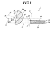
- FIG. 1 is a cross-sectional view showing a portion near the tip of the probe 1.
- the probe 1 includes a light projecting optical fiber 20, a light receiving optical fiber 10, and a lens 30.
- the base end of the probe 1 is connected to a base unit (not shown).
- the base unit includes an excitation light source, a spectroscope, an analysis device, and the like.
- the base end of the light projecting optical fiber 20 is connected to the light source, and the base end of the light receiving optical fiber 10 is connected to the spectroscope.
- Excitation light for example, X-rays, ultraviolet rays, visible light, or electromagnetic waves
- emitted from the light source is incident on the proximal end of the light projecting optical fiber 20 and passes through the light projecting optical fiber 20. Propagates to the tip and exits from the tip.
- the excitation light emitted from the tip of the light projecting optical fiber 20 is projected by the lens 30 onto the measurement site of the living tissue.
- the measurement site of the living tissue is excited by the excitation light, and fluorescence is emitted from the site.
- the fluorescence emitted from the measurement site of the living tissue is condensed by the lens 30 onto the tip of the light receiving optical fiber 10 and is incident on the tip.
- the fluorescence incident on the light receiving optical fiber 10 propagates through the inside of the light receiving optical fiber 10 to the proximal end of the light receiving optical fiber 10 and is input to the spectrometer.
- the light receiving optical fiber 10 has a first optical axis (center line) 11 extending along the light receiving optical fiber 10.
- the light projecting optical fiber 20 has a second optical axis (center line) 21 extending along the light projecting optical fiber 20.
- the distal end portion 13 of the light receiving optical fiber 10 and the distal end portion 23 of the light projecting optical fiber 20 are disposed adjacent to each other.
- the portion 13 near the tip of the light receiving optical fiber 10 may be in contact with the portion 23 near the tip of the projecting optical fiber 20 or may be slightly separated.
- the light receiving optical fiber 10 has an incident surface 12 formed at the tip of the light receiving optical fiber 10.
- the first optical axis 11 of the light receiving optical fiber 10 is orthogonal to the incident surface 12 at the center of the incident surface 12.
- the light projecting optical fiber 20 has an emission surface 22 formed at the tip of the light projecting optical fiber 20.
- the second optical axis 21 of the light projecting optical fiber 20 is orthogonal to the emission surface 22 at the center of the emission surface 22.
- the entrance surface 12 and the exit surface 22 are exposed without being covered with a ferrule.
- the entrance surface 12 and the exit surface 22 are aligned.
- the incident surface 12 and the exit surface 22 may be shifted in the front-rear direction (the direction of the first optical axis 11 and the second optical axis 21), but the entrance surface 12 and the exit surface 22 are close to each other.
- the core diameter of the light receiving optical fiber 10 and the core diameter of the light projecting optical fiber 20 may be the same or different.
- the lens 30 is disposed in front of the incident surface 12 of the light receiving optical fiber 10 and the output surface 22 of the light projecting optical fiber 20.
- the lens 30 is fixed to the holder, and the holder is attached to the ferrule.
- the relative positional relationship among the tip portion 13 of the light receiving optical fiber 10, the tip portion 23 of the light projecting optical fiber 20, and the lens 30 is fixed.
- the lens 30 has a third optical axis (center line) 31.
- the lens 30 has a fiber-facing surface 34 on the rear side (optical fibers 10 and 20 side) and an objective surface 36 on the front side (object side).
- the lens 30 is a plano-convex lens. That is, the fiber-facing surface 34 is a convex surface, and the object surface 36 is a flat surface.
- the fiber face 34 is preferably a convex spherical surface, more preferably a convex hemispherical surface.
- the fiber surface 34 may be a convex aspheric surface.
- the third optical axis 31 is a rotationally symmetric axis, and the fiber surface 34 and the objective surface 36 are rotationally symmetric surfaces around the third optical axis 31.
- the third optical axis 31 intersects the fiber surface 34 at the center (fiber side node) 35 of the fiber surface 34.
- the third optical axis 31 is orthogonal to the object plane 36 at the center (object side node) 37 of the object plane 36.
- This lens 30 has a positive refractive power.
- the focal point 32 of the lens 30 is set on the third optical axis 31 and behind the fiber surface 34.
- a plane passing through the focal point 32 and orthogonal to the third optical axis 31 is a focal plane 33.
- the focal point 32 of the lens 30 is preferably set at or near the incident surface 12 of the light receiving optical fiber 10. Further, it is preferable that the focal point 32 of the lens 30 is set at or near the emission surface 22 of the light projecting optical fiber 20.
- the lens 30 is arranged so that the fiber surface 34 faces the incident surface 12 of the light receiving optical fiber 10 and the light emitting surface 22 of the light projecting optical fiber 20.
- the object plane 36 is for the measurement site of the living tissue.
- the third optical axis 31 of the lens 30, the first optical axis 11 of the light receiving optical fiber 10, and the second optical axis 21 of the light projecting optical fiber 20 are on the same plane.
- the cross section of FIG. 1 is a plane that passes through all of the third optical axis 31 of the lens 30, the first optical axis 11 of the light receiving optical fiber 10, and the second optical axis 21 of the light projecting optical fiber 20.
- both the first optical axis 11 of the light receiving optical fiber 10 and the second optical axis 21 of the light projecting optical fiber 20 intersect the fiber-facing surface 34 of the lens 30.
- the first optical axis 11 of the light receiving optical fiber 10 intersects the fiber-to-fiber surface 34 of the lens 30, and the second optical axis 21 of the light projecting optical fiber 20 does not intersect the fiber-to-fiber surface 34 of the lens 30. May be.
- both the first optical axis 11 of the light receiving optical fiber 10 and the second optical axis 21 of the light projecting optical fiber 20 intersect the objective surface 36 of the lens 30.
- the first optical axis 11 of the light receiving optical fiber 10 intersects the objective surface 36 of the lens 30 and the second optical axis 21 of the light projecting optical fiber 20 does not intersect the objective surface 36 of the lens 30. Good.
- the second optical axis 21 of the light projecting optical fiber 20 is farther away from the center 35 of the fiber surface 34 than the first optical axis 11 of the light receiving optical fiber 10. That is, the distance from the center 35 of the optical fiber surface 34 to the first optical axis 11 of the light receiving optical fiber 10 is L1, and the distance from the center 35 of the optical fiber surface 34 to the second optical axis 21 of the light projecting optical fiber 20 is L1.
- L1 the distance from the center 35 of the optical fiber surface 34 to the first optical axis 11 of the light receiving optical fiber 10
- L1 the distance from the center 35 of the optical fiber surface 34 to the second optical axis 21 of the light projecting optical fiber 20
- a reference line 38 shown in FIG. 1 passes through the center 35 of the fiber surface 34 and is parallel to the first optical axis 11 of the light receiving optical fiber 10 and the second optical axis 21 of the light projecting optical fiber 20. It is a straight line.
- the first optical axis 11 of the light receiving optical fiber 10 is disposed between the second optical axis 21 of the light projecting optical fiber 20 and the reference line 38.
- the reference line 38 may be disposed between the first optical axis 11 of the light receiving optical fiber 10 and the second optical axis 21 of the light projecting optical fiber 20, but even in this case, the above equation (1) is satisfied. Satisfies.
- the third optical axis 31 of the lens 30 may be inclined with respect to the first optical axis 11 of the light receiving optical fiber 10 and the second optical axis 21 of the light projecting optical fiber 20, or the light receiving optical fiber 10.
- the first optical axis 11 and the second optical axis 21 of the projecting optical fiber 20 may be parallel to each other. In any case, the above formula (1) is satisfied.
- the third optical axis 31 of the lens 30 When the third optical axis 31 of the lens 30 is inclined with respect to the first optical axis 11 of the light receiving optical fiber 10 and the second optical axis 21 of the light projecting optical fiber 20, the third optical axis 31 and the reference line 38 crosses at the center 35 of the fiber face 34.
- the third optical axis 31 of the lens 30 is parallel to the first optical axis 11 of the light receiving optical fiber 10 and the second optical axis 21 of the light projecting optical fiber 20, the third optical axis 31 and the reference line 38 are used. Match.
- the third optical axis 31 of the lens 30 is parallel to the first optical axis 11 of the light receiving optical fiber 10 and the second optical axis 21 of the light projecting optical fiber 20, the third optical axis 31 is the light for receiving light. It may coincide with the first optical axis 11 of the fiber 10, or the third optical axis 31 may deviate from the first optical axis 11 of the light receiving optical fiber 10.
- the distance L1 is zero.
- the third optical axis 31 of the lens 30 is parallel to the first optical axis 11 of the light receiving optical fiber 10 and the second optical axis 21 of the light projecting optical fiber 20.
- the focal point 32 of the lens 30 is emitted from the light projecting optical fiber 20.
- the focal point 32 is set in the vicinity of the emission surface 22 while being displaced from the surface 22.
- the third optical axis 31 of the lens 30 is parallel to the first optical axis 11 of the light receiving optical fiber 10 and the second optical axis 21 of the light projecting optical fiber 20, and the third optical axis 31 of the lens 30 is When it does not coincide with the first optical axis 11 of the light receiving optical fiber 10, the focal point 32 of the lens 30 is displaced from the incident surface 12 of the light receiving optical fiber 10 and the output surface 22 of the light projecting optical fiber 20, and The focal point 32 is set near the entrance surface 12 and the exit surface 22. When the third optical axis 31 of the lens 30 coincides with the first optical axis 11 of the light receiving optical fiber 10, the focal point 32 of the lens 30 is set at or near the incident surface 12 of the light receiving optical fiber 10. .
- the focal point 32 of the lens 30 is for light receiving.
- One of the incident surface 12 of the optical fiber 10 and the exit surface 22 of the projecting optical fiber 20 is set in the vicinity thereof, and the focal point 32 is set in the vicinity thereof by shifting from the other.
- the excitation light emitted from the emission surface 22 of the light projecting optical fiber 20 is collimated by the lens 30. That is, the excitation light emitted from the emission surface 22 of the light projecting optical fiber 20 is projected onto the measurement site of the living tissue as substantially parallel light.
- the excitation light that is substantially parallel light is not necessarily parallel to the third optical axis 31 of the lens 30.
- Fluorescence emitted from the measurement site of the living tissue by the excitation light is condensed by the lens 30 onto the incident surface 12 of the light receiving optical fiber 10 and is incident on the incident surface 12.
- a mirror may be disposed between the incident surface 12 of the light receiving optical fiber 10 and the light emitting surface 22 of the light projecting optical fiber 20 and the fiber-facing surface 34 of the lens 30.
- the excitation light emitted from the emission surface 22 of the light projecting optical fiber 20 is reflected by the mirror and enters the fiber-facing surface 34 of the lens 30.
- the fluorescence emitted from the measurement site of the living tissue and projected by the lens 30 is reflected by the mirror and enters the incident surface 12 of the light receiving optical fiber 10.
- the first optical axis 11 of the light receiving optical fiber 10 and the second optical axis 21 of the light projecting optical fiber 20 are bent by a mirror. This applies to the portion of the optical axis 21 closer to the lens 30 than the mirror.
- the relative positional relationship among the light receiving optical fiber 10, the light projecting optical fiber 20, and the lens 30 is optimally set as described above, and particularly satisfies the above equation (1), the following (1) to There is an effect as in (3).
- (1) The fluorescence emitted from the measurement site of the living tissue is efficiently incident on the incident surface 12 of the light receiving optical fiber 10. That is, it is possible to suppress a decrease in fluorescence intensity incident on the incident surface 12 of the light receiving optical fiber 10.
- Light reflection noise on the fiber surface 34 and the object surface 36 of the lens 30 can be reduced.
- the so-called SN ratio can be increased, and the influence of light reflection noise on the fiber-to-fiber surface 34 and the object surface 36 of the lens 30 is small.
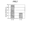
- FIG. 2 is a graph showing the intensity of fluorescence incident on the incident surface 12 of the light receiving optical fiber 10.
- the efficiency (ratio) of the intensity of the fluorescence incident on the incident surface 12 of the light receiving optical fiber 10 is obtained by simulation, assuming that the intensity of the fluorescence emitted from the measurement site of the living tissue is 100%.
- the efficiency of the intensity of the fluorescence incident on the incident surface 12 of the light receiving optical fiber 10 is high, but the formula (1) is not satisfied. In this case, the efficiency of the intensity of fluorescence incident on the incident surface 12 of the light receiving optical fiber 10 is low.
- the case where the third optical axis 31 of the lens 30 coincides with the first optical axis 11 of the light receiving optical fiber 10 will be specifically described (second embodiment).
- the third optical axis 31 of the lens 30 is parallel to the first optical axis 11 of the light receiving optical fiber 10 and the second optical axis 21 of the light projecting optical fiber 20, and the third optical axis of the lens 30.
- the case where 31 is deviated from the first optical axis 11 of the light receiving optical fiber 10 will also be described specifically (third embodiment).
- the case where the third optical axis 31 of the lens 30 is tilted with respect to the first optical axis 11 of the light receiving optical fiber 10 and the second optical axis 21 of the light projecting optical fiber 20 will also be specifically described.
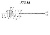
- FIG. 3A is a cross-sectional view showing a portion near the tip of the probe 1 when the third optical axis 31 of the lens 30 coincides with the first optical axis 11 of the light receiving optical fiber 10.
- FIG. 3B shows only the light receiving optical fiber 10, the light projecting optical fiber 20, and the lens 30.
- the light receiving optical fiber 10 and the light projecting optical fiber 20 are passed through the tube 40 from one end to the other end of the tubular tube 40.
- the tube 40 has flexibility.
- Tubular lens holder 70 and tube 40 are jointed by ferrule holder 60. That is, a part of the ferrule holder 60 is fitted into the opening at the end of the tube 40, and another part of the ferrule holder 60 is fitted into the opening at the end of the lens holder 70.
- the ferrule holder 60 is provided in a tubular shape, and the ferrule 50 is fitted in the ferrule holder 60.
- the tip portion 13 of the light receiving optical fiber 10 and the tip portion 23 of the projecting optical fiber 20 penetrate from the one end surface 51 to the other end surface 52 of the ferrule 50, and the incident surface 12 and the projecting light of the light receiving optical fiber 10.
- the exit surface 22 of the optical fiber 20 is exposed on the other end side of the ferrule 50.
- a tip portion 13 of the light receiving optical fiber 10 and a tip portion 23 of the light projecting optical fiber 20 are in contact with each other.
- An incident surface 12 of the light receiving optical fiber 10 and an output surface 22 of the light projecting optical fiber 20 are aligned. Further, the end face of the ferrule 50 is also aligned with the entrance surface 12 and the exit surface 22.
- the lens 30 is fixed to the lens holder 70 in the lens holder 70. The above equation (1) is satisfied, and the distance L1 is zero.
- the numerical aperture at the exit surface 22 of the light projecting optical fiber 20 is NA
- the effective diameter (diameter) of the lens 30 is ⁇
- the incident surface 12 of the light receiving optical fiber 10 from the center 35 of the lens 30 with respect to the fiber surface 34 and
- the upper limit of the distance L2 is set by the equation (2). That is, the amount (distance L 2) of the second optical axis 21 of the projecting optical fiber 20 from the third optical axis 31 of the lens 30 is the characteristic of the lens 30 and the positional relationship between the lens 30 and the optical fibers 10 and 20. And the spread of the light emitted from the emission surface 22 of the light projecting optical fiber 20 is limited. Conversely, if the distance L2 is determined, the characteristics of the lens 30 and the light projecting optical fiber 20 are limited.
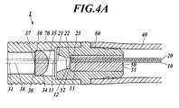
- the third optical axis 31 of the lens 30 is parallel to the first optical axis 11 of the light receiving optical fiber 10 and the second optical axis 21 of the light projecting optical fiber 20, and 4 is a cross-sectional view showing a portion near the tip of the probe 1 when the optical axis 31 is deviated from the first optical axis 11 of the light receiving optical fiber 10.
- FIG. 4B shows only the light receiving optical fiber 10, the light projecting optical fiber 20, and the lens 30.
- the tube 40, the ferrule 50, the ferrule holder 60, and the lens holder 70 are the same as those in the second embodiment, their descriptions are omitted.
- the distal end portion 13 of the light receiving optical fiber 10 and the distal end portion 23 of the light projecting optical fiber 20 are fixed to the ferrule 50, and the portions 13, 23 are in contact with each other from the distal end.
- An incident surface 12 of the light receiving optical fiber 10 and an output surface 22 of the light projecting optical fiber 20 are aligned.
- the above equation (1) is satisfied.
- the first optical axis 11 of the light receiving optical fiber 10 is disposed between the second optical axis 21 of the light projecting optical fiber 20 and the third optical axis 31 of the lens 30.
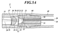
- FIG. 5A shows the tip of the probe 1 when the third optical axis 31 of the lens 30 is inclined with respect to the first optical axis 11 of the light receiving optical fiber 10 and the second optical axis 21 of the light projecting optical fiber 20. It is sectional drawing which showed the near part.
- FIG. 5B shows only the light receiving optical fiber 10, the light projecting optical fiber 20, and the lens 30.
- the tube 40, the ferrule 50, the ferrule holder 60, and the lens holder 70 are the same as those in the second embodiment, their descriptions are omitted.
- the third optical axis 31 of the lens 30 fixed to the lens holder 70 crosses the first optical axis 11 of the light receiving optical fiber 10. Furthermore, the third optical axis 31 of the lens 30 also crosses the second optical axis 21 of the light projecting optical fiber 20 obliquely.
- the above equation (1) is satisfied.
- the first optical axis 11 of the light receiving optical fiber 10 is disposed between the second optical axis 21 of the light projecting optical fiber 20 and the reference line 38.
- the inclination angle of the third optical axis 31 of the lens 30 is ⁇
- the numerical aperture at the exit surface 22 of the light projecting optical fiber 20 is NA
- the lens 30 is effective.
- the upper limit of the distance L2 is set by Equation (3). By satisfying Expression (3), it is possible to prevent vignetting of the excitation light emitted from the emission surface 22 of the light projecting optical fiber 20.
- ⁇ is the effective diameter of the lens
- f is the focal length of the lens
- R is the radius of the lens
- NA is the numerical aperture at the exit surface 22 of the light projecting optical fiber
- NA2 is the numerical aperture at the incident surface 12 of the light receiving optical fiber
- D is the distance from the lens 30 to the target (which emits fluorescence)
- r1 is the diameter r1 of the core of the light projecting optical fiber 20.
- R2 is the diameter of the core of the light receiving optical fiber
- L2 is the distance L2 from the center 35 of the optical fiber surface 34 to the second optical axis 21 of the light projecting optical fiber 20 (Example 2 described later). The same applies to Example 3.)
- the intensity of scattered light incident on the incident surface 12 of the light receiving optical fiber 10 was determined by simulation by changing the distance d from the center 35 of the fiber surface 34 to the incident surface 12 of the light receiving optical fiber 10.
- the intensity of the reflected noise of the scattered light on the fiber surface 34 and the objective surface 36 of the lens 30 was obtained by simulation.
- the S / N ratio was also obtained by simulation.
- the scattered light at the measurement site is simulated instead of the fluorescence at the measurement site.
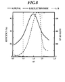
- the legend “A) signal” in the figure indicates the intensity ratio (efficiency) of scattered light incident on the incident surface 12 of the light receiving optical fiber 10 with the intensity of light emitted from the light projecting optical fiber 20 being 100%.
- the legend “B) Reflection noise” in the figure reflects the light intensity of the light emitted from the light projecting optical fiber as 100% and reflects it on the fiber-facing surface 34, the object surface 36, etc. of the lens 30, and receives the light receiving optical fiber 10. Represents the ratio (efficiency) of the intensity of the scattered light not incident on the incident surface 12.
- the legend “A / B” in the figure represents the SN ratio.
- the range of 0.9 ⁇ d / f ⁇ 2.20 is an optimal range with sufficiently low noise and high efficiency.
- the range of d / f is considered to be from a distance slightly shorter than the focal length f to an upper limit determined by the distance L2.
- the third optical axis 31 of the lens 30 is parallel to the first optical axis 11 of the light receiving optical fiber 10 and the second optical axis 21 of the light projecting optical fiber 20, and the third optical axis 31 of the lens 30 is A simulation was performed for the case where the optical fiber 10 for receiving light is deviated from the first optical axis 11 (see FIG. 4A).
- the range of 0.8 ⁇ d / f ⁇ 2.0 is an optimal range with sufficiently low noise and high efficiency.
- a simulation is performed when the third optical axis 31 of the lens 30 is inclined with respect to the first optical axis 11 of the light receiving optical fiber 10 and the second optical axis 21 of the light projecting optical fiber 20 (see FIG. 5A). did.
- D 1.7mm
- the range of 1.0 ⁇ d / f ⁇ 1.9 is an optimal range with sufficiently low noise and high efficiency.
- the noise is reduced by tilting the lens 30 in a direction that diverts the reflection of the lens 30.
- the lower limit of the distance d from the center 35 of the fiber surface 34 to the incident surface 12 of the light receiving optical fiber 10 is in the vicinity of the focal length f, and the upper limit of the distance d is the upper limit in the equation (3).
- the light receiving efficiency of light, the reflection noise of the lens 30, and the ratio thereof were obtained by simulation.
- the reflection noise of the lens 30 is reduced by shifting the second optical axis 21 of the light projecting optical fiber 20 from the reference line 38 or the third optical axis 31 of the lens 30 or tilting the lens 30. It was supported by simulation. However, the distance L1 from the center 35 of the optical fiber surface 34 to the first optical axis 11 of the light receiving optical fiber 10 and the distance L2 from the center 35 of the optical fiber surface 34 to the second optical axis 21 of the light projecting optical fiber 20 are shown.
- the inclination angle ⁇ of the lens 30 is the shape of the lens 30, the spread of the excitation light emitted from the emission surface 22 of the light projecting optical fiber 20 (numerical aperture NA), and the distance d between the lens 30 and the optical fibers 10 and 20. Limited by. This is shown by formulas (2) and (3). Considering the above, the lower limit of the distance d between the lens 30 and the optical fibers 10 and 20 is in the vicinity of the focal length f of the lens 30, and the upper limits of the distance d are the distance L1, the distance L2, and the inclination. It was shown that the limit value is limited by the angle ⁇ .
- the present invention can be used for a probe that irradiates a measurement site of a living tissue with light and receives light emitted from the measurement site.
Landscapes
- Health & Medical Sciences (AREA)
- Life Sciences & Earth Sciences (AREA)
- Surgery (AREA)
- Physics & Mathematics (AREA)
- General Health & Medical Sciences (AREA)
- Pathology (AREA)
- Biomedical Technology (AREA)
- Medical Informatics (AREA)
- Molecular Biology (AREA)
- Engineering & Computer Science (AREA)
- Animal Behavior & Ethology (AREA)
- Biophysics (AREA)
- Public Health (AREA)
- Veterinary Medicine (AREA)
- Heart & Thoracic Surgery (AREA)
- Nuclear Medicine, Radiotherapy & Molecular Imaging (AREA)
- Optics & Photonics (AREA)
- Radiology & Medical Imaging (AREA)
- Biochemistry (AREA)
- General Physics & Mathematics (AREA)
- Immunology (AREA)
- Analytical Chemistry (AREA)
- Chemical & Material Sciences (AREA)
- Investigating Or Analysing Materials By Optical Means (AREA)
- Instruments For Viewing The Inside Of Hollow Bodies (AREA)
- Endoscopes (AREA)
- Investigating, Analyzing Materials By Fluorescence Or Luminescence (AREA)
Abstract
Description
特許文献2には、カップリング用のレンズを2本の光ファイバの先端面の前に配置し、一方の光ファイバをフェルールの軸に沿って配置し、他方の光ファイバをフェルールの軸から偏心させ、これら二本の光ファイバ及びフェルールの端面を揃えるとともに、それらの端面を光ファイバの光軸に対して傾斜させる技術が開示されている。
特許文献3には、単一のマルチモード光ファイバとLEDの間に複数枚のレンズを配置し、LEDから発した光を複数枚のレンズによってマルチモード光ファイバの先端に集光させる技術が開示されている。
そこで、本発明が解決しようとする課題は、生体組織の測定部位から発した光が効率よく受光用光ファイバの先端に入射できるようにするとともに、レンズの表面等における反射ノイズの低減を図ることである。
本発明に係るプローブが、
第一光軸を有するとともに、前記第一光軸に対して直交する入射面を先端に有する受光用光ファイバと、
前記第一光軸に対して平行な第二光軸を有するとともに、前記第二光軸に対して直交する出射面を先端に有する投光用光ファイバと、
正の屈折力を有し、前記投光用光ファイバの前記出射面から出射した光を生体組織の測定部位に投射するとともに、生体組織の測定部位から発した光を前記受光用光ファイバの前記入射面に集光させるレンズと、を備え、
前記レンズが、前記入射面及び前記出射面に対する凸面と、前記凸面の反対側に形成された平面と、前記凸面の中心で前記凸面に交差するとともに前記平面の中心で前記平面に直交する第三光軸と、を有し、
前記凸面の前記中心から前記第一光軸までの距離が、前記凸面の前記中心から前記第二光軸までの距離よりも短いことした。


また、レンズの表面等における光の反射ノイズを軽減することができる。
図1は、プローブ1の先端寄り部分を示した断面図である。
このプローブ1は、投光用光ファイバ20、受光用光ファイバ10及びレンズ30を備える。
L1<L2 …(1)
レンズ30の第三光軸31が受光用光ファイバ10の第一光軸11及び投光用光ファイバ20の第二光軸21に対して平行であって、レンズ30の第三光軸31が受光用光ファイバ10の第一光軸11に一致していない場合、レンズ30の焦点32が受光用光ファイバ10の入射面12及び投光用光ファイバ20の出射面22からずれているとともに、その焦点32入射面12及び出射面22の近傍に設定されている。
レンズ30の第三光軸31が受光用光ファイバ10の第一光軸11に一致している場合、レンズ30の焦点32が受光用光ファイバ10の入射面12又はその近傍に設定されている。
レンズ30の第三光軸31が受光用光ファイバ10の第一光軸11及び投光用光ファイバ20の第二光軸21に対して傾斜している場合、レンズ30の焦点32が受光用光ファイバ10の入射面12と投光用光ファイバ20の出射面22のうちのどちらか一方又はその近傍に設定され、その焦点32が他方からずれてその近傍に設定されている。
(1) 生体組織の測定部位から発した蛍光が効率よく受光用光ファイバ10の入射面12に入射する。つまり、受光用光ファイバ10の入射面12に入射する蛍光強度の低下を抑えることができる。
(2) レンズ30の対ファイバ面34や対物面36における光の反射ノイズを軽減することができる。
(3) いわゆるSN比を高くすることができ、レンズ30の対ファイバ面34や対物面36における光の反射ノイズの影響が小さい。
図3Aは、レンズ30の第三光軸31が受光用光ファイバ10の第一光軸11に一致している場合、プローブ1の先端寄り部分を示した断面図である。図3Bは、受光用光ファイバ10、投光用光ファイバ20及びレンズ30のみを示した図面である。
レンズ30は、レンズホルダ70内でレンズホルダ70に固定されている。
上述の式(1)を満たしており、距離L1がゼロである。

図4Aは、レンズ30の第三光軸31が受光用光ファイバ10の第一光軸11及び投光用光ファイバ20の第二光軸21に対して平行であって、レンズ30の第三光軸31が受光用光ファイバ10の第一光軸11からずれている場合、プローブ1の先端寄り部分を示した断面図である。図4Bは、受光用光ファイバ10、投光用光ファイバ20及びレンズ30のみを示した図面である。
図5Aは、レンズ30の第三光軸31が受光用光ファイバ10の第一光軸11及び投光用光ファイバ20の第二光軸21に対して傾斜している場合、プローブ1の先端寄り部分を示した断面図である。図5Bは、受光用光ファイバ10、投光用光ファイバ20及びレンズ30のみを示した図面である。

φ=1.36mm
f=1.125mm
R=0.68mm
NA=0.22
NA2=0.22
D=1.7mm
r1=0.1mm
r2=0.1mm
L2=0.11mm
これにより、対ファイバ面34の中心35から受光用光ファイバ10の入射面12までの距離dの上限が定まる。図6のグラフ中、d/f≦2.2となる範囲では、ターゲットから発した光が効率よく受光用光ファイバ10の入射面12に入射することがわかる(凡例「A) signal」参照)。更に、反射ノイズが低く、SN比が高いことがわかる(凡例「B) Reflection noise」、凡例「A/B」参照)。
φ=1.36mm
f=1.125mm
R=0.68mm
NA=0.22
NA2=0.22
D=1.7mm
r1=0.1mm
r2=0.1mm
L2=0.15mm
式(2)にL2=0.15を代入すると、d≦2.3となり、d/f≦2.0となる。
これにより、対ファイバ面34の中心35から受光用光ファイバ10の入射面12までの距離dの上限が定まる。図7のグラフ中、d/f≦2.0となる範囲では、ターゲットから発した光が効率よく受光用光ファイバ10の入射面12に入射し、反射ノイズが低く、SN比が高いことがわかる。
φ=1.36mm
f=1.125mm
R=0.68mm
NA=0.22
NA2=0.22
D=1.7mm
r1=0.1mm
r2=0.1mm
L2=0.25mm
θ=5°
なお、θは、第一光軸11、第二光軸21及び基準線38に対するレンズ30の第三光軸31の傾斜角である。
式(3)にL2=0.25を代入すると、d≦2.1となり、d/f≦1.9となる。これにより、対ファイバ面34の中心35から受光用光ファイバ10の入射面12までの距離dの上限が定まる。図8のグラフ中、d/f≦1.9となる範囲では、ターゲットから発した光が効率よく受光用光ファイバ10の入射面12に入射し、反射ノイズが低く、SN比が高いことがわかる。
しかし、対ファイバ面34の中心35から受光用光ファイバ10の第一光軸11までの距離L1、対ファイバ面34の中心35から投光用光ファイバ20の第二光軸21までの距離L2、レンズ30の傾斜角θは、レンズ30の形状、投光用光ファイバ20の出射面22から出射する励起光の広がり(開口数NA)、レンズ30と光ファイバ10,20の間の距離dにより制限される。そのことを式(2)、式(3)により示した。
以上のことを考慮して、レンズ30と光ファイバ10,20の間の距離dの下限としては、レンズ30の焦点距離f近傍であり、距離dの上限としては、距離L1、距離L2及び傾斜角θにより制限される限界値であることを示した。
10 受光用光ファイバ
11 第一光軸
12 入射面
20 投光用光ファイバ
21 第二光軸
22 出射面
30 レンズ
31 第三光軸
34 対ファイバ面(凸面)
35 中心
36 対物面(平面)
Claims (6)
- 第一光軸を有するとともに、前記第一光軸に対して直交する入射面を先端に有する受光用光ファイバと、
前記第一光軸に対して平行な第二光軸を有するとともに、前記第二光軸に対して直交する出射面を先端に有する投光用光ファイバと、
正の屈折力を有し、前記投光用光ファイバの前記出射面から出射した光を生体組織の測定部位に投射するとともに、生体組織の測定部位から発した光を前記受光用光ファイバの前記入射面に集光させるレンズと、を備え、
前記レンズが、前記入射面及び前記出射面に対する凸面と、前記凸面の反対側に形成された平面と、前記凸面の中心で前記凸面に交差するとともに前記平面の中心で前記平面に直交する第三光軸と、を有し、
前記凸面の前記中心から前記第一光軸までの距離が、前記凸面の前記中心から前記第二光軸までの距離よりも短い、プローブ。 - 前記第一光軸、前記第二光軸及び前記第三光軸が互いに平行である、請求項1のプローブ。
- 前記投光用光ファイバの前記出射面における開口数をNAとし、前記レンズの有効径をφとし、前記レンズの前記凸面の中心から前記受光用光ファイバの入射面及び前記投光用光ファイバの前記出射面までの距離をdとし、前記凸面の中心から前記第二光軸までの距離をL2とすると、

- 前記第三光軸と前記第一光軸が揃っている、請求項2又は3のプローブ。
- 前記第三光軸が前記第一光軸に対して傾斜している、請求項1のプローブ。
- 前記第一光軸に対する前記第三光軸の傾斜角をθとし、前記投光用光ファイバの前記出射面における開口数をNAとし、前記レンズの有効径をφとし、前記レンズの前記凸面の中心から前記受光用光ファイバの入射面及び前記投光用光ファイバの前記出射面までの距離をdとし、前記凸面の中心から前記第二光軸までの距離をL2とすると、

Priority Applications (4)
| Application Number | Priority Date | Filing Date | Title |
|---|---|---|---|
| EP11849660.3A EP2653090A4 (en) | 2010-12-16 | 2011-12-14 | PROBE |
| US13/995,097 US9456753B2 (en) | 2010-12-16 | 2011-12-14 | Probe |
| CN201180060367.7A CN103260497B (zh) | 2010-12-16 | 2011-12-14 | 探头 |
| JP2012548800A JP5772831B2 (ja) | 2010-12-16 | 2011-12-14 | プローブ |
Applications Claiming Priority (2)
| Application Number | Priority Date | Filing Date | Title |
|---|---|---|---|
| JP2010280557 | 2010-12-16 | ||
| JP2010-280557 | 2010-12-16 |
Publications (1)
| Publication Number | Publication Date |
|---|---|
| WO2012081599A1 true WO2012081599A1 (ja) | 2012-06-21 |
Family
ID=46244696
Family Applications (1)
| Application Number | Title | Priority Date | Filing Date |
|---|---|---|---|
| PCT/JP2011/078865 Ceased WO2012081599A1 (ja) | 2010-12-16 | 2011-12-14 | プローブ |
Country Status (5)
| Country | Link |
|---|---|
| US (1) | US9456753B2 (ja) |
| EP (1) | EP2653090A4 (ja) |
| JP (1) | JP5772831B2 (ja) |
| CN (1) | CN103260497B (ja) |
| WO (1) | WO2012081599A1 (ja) |
Cited By (1)
| Publication number | Priority date | Publication date | Assignee | Title |
|---|---|---|---|---|
| EP3032996A4 (en) * | 2013-08-13 | 2017-05-17 | HOYA Corporation | Illumination optical system for endoscope |
Families Citing this family (1)
| Publication number | Priority date | Publication date | Assignee | Title |
|---|---|---|---|---|
| WO2016061754A1 (zh) * | 2014-10-22 | 2016-04-28 | 中国科学院自动化研究所 | 一种手持式分子影像导航系统 |
Citations (7)
| Publication number | Priority date | Publication date | Assignee | Title |
|---|---|---|---|---|
| JPH1062653A (ja) | 1996-08-22 | 1998-03-06 | Kyocera Corp | 多芯フェルール |
| JP2001174712A (ja) * | 1999-10-07 | 2001-06-29 | Olympus Optical Co Ltd | 内視鏡光学系 |
| WO2002071115A1 (en) | 2001-02-06 | 2002-09-12 | Oyokoden Lab Co., Ltd | Optical part |
| JP2004317437A (ja) * | 2003-04-18 | 2004-11-11 | Olympus Corp | 光イメージング装置 |
| JP2008197241A (ja) | 2007-02-09 | 2008-08-28 | Nippon Sheet Glass Co Ltd | 光モジュール |
| JP2010051606A (ja) * | 2008-08-29 | 2010-03-11 | Fujifilm Corp | 照明光学系及びこれを用いる内視鏡 |
| JP2010088665A (ja) * | 2008-10-08 | 2010-04-22 | Olympus Corp | 内視鏡 |
Family Cites Families (14)
| Publication number | Priority date | Publication date | Assignee | Title |
|---|---|---|---|---|
| GB2066449B (en) * | 1979-12-21 | 1984-03-21 | Rolls Royce | Monitoring distance variations |
| JPH01244416A (ja) * | 1988-03-25 | 1989-09-28 | Olympus Optical Co Ltd | 内視鏡 |
| JPH03107751A (ja) * | 1989-09-20 | 1991-05-08 | Nok Corp | 表面検査装置 |
| US5573493A (en) * | 1993-10-08 | 1996-11-12 | United States Surgical Corporation | Endoscope attachment for changing angle of view |
| US5671084A (en) * | 1995-03-24 | 1997-09-23 | Eastman Kodak Company | Illumination system for a film scanner |
| JP3887481B2 (ja) * | 1998-03-26 | 2007-02-28 | 株式会社キリンテクノシステム | 表面検査装置 |
| US7239782B1 (en) * | 2004-09-03 | 2007-07-03 | Chemimage Corporation | Chemical imaging fiberscope |
| US6663560B2 (en) * | 1999-12-17 | 2003-12-16 | Digital Optical Imaging Corporation | Methods and apparatus for imaging using a light guide bundle and a spatial light modulator |
| US6863651B2 (en) * | 2001-10-19 | 2005-03-08 | Visionscope, Llc | Miniature endoscope with imaging fiber system |
| US7647092B2 (en) | 2002-04-05 | 2010-01-12 | Massachusetts Institute Of Technology | Systems and methods for spectroscopy of biological tissue |
| EP1495309A1 (en) | 2002-04-05 | 2005-01-12 | Massachusetts Institute Of Technology | Systems and methods for spectroscopy of biological tissue |
| CN2615688Y (zh) * | 2003-04-28 | 2004-05-12 | 南开大学 | 细径柔性光纤显微内窥镜装置 |
| JP2007225673A (ja) * | 2006-02-21 | 2007-09-06 | Hitachi Metals Ltd | 光パワーモニターおよびその製造方法 |
| WO2012056991A1 (ja) * | 2010-10-26 | 2012-05-03 | コニカミノルタオプト株式会社 | プローブ |
-
2011
- 2011-12-14 JP JP2012548800A patent/JP5772831B2/ja not_active Expired - Fee Related
- 2011-12-14 WO PCT/JP2011/078865 patent/WO2012081599A1/ja not_active Ceased
- 2011-12-14 US US13/995,097 patent/US9456753B2/en not_active Expired - Fee Related
- 2011-12-14 EP EP11849660.3A patent/EP2653090A4/en not_active Withdrawn
- 2011-12-14 CN CN201180060367.7A patent/CN103260497B/zh not_active Expired - Fee Related
Patent Citations (7)
| Publication number | Priority date | Publication date | Assignee | Title |
|---|---|---|---|---|
| JPH1062653A (ja) | 1996-08-22 | 1998-03-06 | Kyocera Corp | 多芯フェルール |
| JP2001174712A (ja) * | 1999-10-07 | 2001-06-29 | Olympus Optical Co Ltd | 内視鏡光学系 |
| WO2002071115A1 (en) | 2001-02-06 | 2002-09-12 | Oyokoden Lab Co., Ltd | Optical part |
| JP2004317437A (ja) * | 2003-04-18 | 2004-11-11 | Olympus Corp | 光イメージング装置 |
| JP2008197241A (ja) | 2007-02-09 | 2008-08-28 | Nippon Sheet Glass Co Ltd | 光モジュール |
| JP2010051606A (ja) * | 2008-08-29 | 2010-03-11 | Fujifilm Corp | 照明光学系及びこれを用いる内視鏡 |
| JP2010088665A (ja) * | 2008-10-08 | 2010-04-22 | Olympus Corp | 内視鏡 |
Non-Patent Citations (1)
| Title |
|---|
| See also references of EP2653090A4 |
Cited By (2)
| Publication number | Priority date | Publication date | Assignee | Title |
|---|---|---|---|---|
| EP3032996A4 (en) * | 2013-08-13 | 2017-05-17 | HOYA Corporation | Illumination optical system for endoscope |
| US9671606B2 (en) | 2013-08-13 | 2017-06-06 | Hoya Corporation | Illumination optical system for endoscope |
Also Published As
| Publication number | Publication date |
|---|---|
| US20130267857A1 (en) | 2013-10-10 |
| CN103260497A (zh) | 2013-08-21 |
| EP2653090A4 (en) | 2016-11-16 |
| JP5772831B2 (ja) | 2015-09-02 |
| EP2653090A1 (en) | 2013-10-23 |
| JPWO2012081599A1 (ja) | 2014-05-22 |
| US9456753B2 (en) | 2016-10-04 |
| CN103260497B (zh) | 2015-08-12 |
Similar Documents
| Publication | Publication Date | Title |
|---|---|---|
| JP6397431B2 (ja) | リモート分光法のための光ファイバプローブ | |
| ES2841101T3 (es) | Elementos ópticos miniatura para la conformación de haz de fibra óptica y procedimiento de recogida de datos ópticos | |
| US10816789B2 (en) | Optical probes that include optical-correction components for astigmatism correction | |
| JP6823091B2 (ja) | 非点収差補正のための反射構成要素を有する光学プローブ | |
| JP6821718B2 (ja) | 光学補正構成要素を有する光学プローブ | |
| JP2009178229A (ja) | Octプローブ | |
| JP7623997B2 (ja) | テーパ状光伝送素子を有する光学システム | |
| JP5959652B2 (ja) | 散乱光計測装置 | |
| CN103237489B (zh) | 探针 | |
| JP5772831B2 (ja) | プローブ | |
| JP2007132792A (ja) | 光計測装置と試料との光結合系 | |
| WO2012157552A1 (ja) | プローブ | |
| CN111443063B (zh) | 内窥扫描设备 | |
| JP6888638B2 (ja) | 光源装置およびこれを備えた測距センサ | |
| JP2006195390A (ja) | レーザ走査型蛍光顕微鏡および検出光学系ユニット | |
| JP2009174985A (ja) | 光ファイバ内視生体検査装置及び光ファイバ内視生体検査システム | |
| JP5650551B2 (ja) | ファイバスコープ装置 | |
| WO2017150154A1 (ja) | 内視鏡 | |
| JP2020018494A (ja) | 光源ユニット、及びそれを有する光音響装置 | |
| WO2025199128A1 (en) | Dual off-axis parabolic mirrors-based capsule | |
| JP2006043248A (ja) | 光源装置 | |
| JP2024538380A5 (ja) | ||
| WO2017010465A1 (ja) | 血管判定システム | |
| JP2017018483A (ja) | 医療用プローブ |
Legal Events
| Date | Code | Title | Description |
|---|---|---|---|
| 121 | Ep: the epo has been informed by wipo that ep was designated in this application |
Ref document number: 11849660 Country of ref document: EP Kind code of ref document: A1 |
|
| ENP | Entry into the national phase |
Ref document number: 2012548800 Country of ref document: JP Kind code of ref document: A |
|
| WWE | Wipo information: entry into national phase |
Ref document number: 2011849660 Country of ref document: EP |
|
| NENP | Non-entry into the national phase |
Ref country code: DE |
|
| WWE | Wipo information: entry into national phase |
Ref document number: 13995097 Country of ref document: US |