WO2012086020A1 - Boîte d'épingles à cheveux - Google Patents
Boîte d'épingles à cheveux Download PDFInfo
- Publication number
- WO2012086020A1 WO2012086020A1 PCT/JP2010/073075 JP2010073075W WO2012086020A1 WO 2012086020 A1 WO2012086020 A1 WO 2012086020A1 JP 2010073075 W JP2010073075 W JP 2010073075W WO 2012086020 A1 WO2012086020 A1 WO 2012086020A1
- Authority
- WO
- WIPO (PCT)
- Prior art keywords
- case
- hairpin
- case cover
- cover
- main body
- Prior art date
- Legal status (The legal status is an assumption and is not a legal conclusion. Google has not performed a legal analysis and makes no representation as to the accuracy of the status listed.)
- Ceased
Links
Images




Classifications
-
- A—HUMAN NECESSITIES
- A45—HAND OR TRAVELLING ARTICLES
- A45C—PURSES; LUGGAGE; HAND CARRIED BAGS
- A45C13/00—Details; Accessories
- A45C13/02—Interior fittings; Means, e.g. inserts, for holding and packing articles
-
- A—HUMAN NECESSITIES
- A45—HAND OR TRAVELLING ARTICLES
- A45C—PURSES; LUGGAGE; HAND CARRIED BAGS
- A45C11/00—Receptacles for purposes not provided for in groups A45C1/00-A45C9/00
- A45C11/24—Etuis for purposes not covered by a single one of groups A45C11/02 - A45C11/22, A45C11/26, A45C11/32 - A45C11/38
-
- A—HUMAN NECESSITIES
- A45—HAND OR TRAVELLING ARTICLES
- A45C—PURSES; LUGGAGE; HAND CARRIED BAGS
- A45C13/00—Details; Accessories
- A45C13/10—Arrangement of fasteners
- A45C13/1076—Arrangement of fasteners with a snap action
- A45C13/1084—Arrangement of fasteners with a snap action of the latch-and-catch type
-
- A—HUMAN NECESSITIES
- A45—HAND OR TRAVELLING ARTICLES
- A45D—HAIRDRESSING OR SHAVING EQUIPMENT; EQUIPMENT FOR COSMETICS OR COSMETIC TREATMENTS, e.g. FOR MANICURING OR PEDICURING
- A45D44/00—Other cosmetic or toiletry articles, e.g. for hairdressers' rooms
- A45D44/02—Furniture or other equipment specially adapted for hairdressers' rooms and not covered elsewhere
-
- A—HUMAN NECESSITIES
- A45—HAND OR TRAVELLING ARTICLES
- A45D—HAIRDRESSING OR SHAVING EQUIPMENT; EQUIPMENT FOR COSMETICS OR COSMETIC TREATMENTS, e.g. FOR MANICURING OR PEDICURING
- A45D8/00—Hair-holding devices; Accessories therefor
- A45D8/02—Hair pins
- A45D8/06—Hair pins two-limbed, e.g. U-shaped
Definitions
- the present invention relates to a hairpin case that houses a hairpin used when setting a hairstyle.
- a hairpin has been used to hold a human hair in a desired hairstyle.
- hairdressers including barbers
- the hairpins into the same type, store them in a ready-made case, The necessary number is taken out from the case and used.
- a case for storing a hairpin a case in which the inside of the case is partitioned into a plurality of storage compartments by a partition member as disclosed in, for example, Patent Document 1 is known.
- a lid that opens and closes by swinging is provided at the opening of the case, and the inside of the case can be closed.
- the hairdresser When attaching a hairpin to the hair, the hairdresser opens the leg of the hairpin and sandwiches the hair to be fixed between them. For this reason, at the time of wearing, the legs of the hairpin were opened by applying force with fingers or nails, or the other leg was opened with a finger while holding one leg with the mouth or teeth.
- the present invention was made in view of the above circumstances, and makes it easy to open and handle the hairpin, and when using it with the lid open, without taking up space,
- An object of the present invention is to provide a hairpin case that does not interfere with other operations.
- the present invention has taken the following measures. That is, the first specific means for solving the problems in the present invention is to hold the hairpin between the case main body in which the interior is partitioned by the front and rear and / or left and right partition sections to form a plurality of storage sections.
- a flange-shaped flange opener protruding outward is provided on the outer surface of the side wall, and / or a partition opener that is thicker below the upper edge than the upper edge is provided on the upper part of the partition. It is that you are.
- the hairpin classified beforehand can be separately accommodated in the some accommodating part in a case main body. Further, by using the flange opener and / or the partition opener, the hairpin can be easily opened, and a plurality of hairpins can be sandwiched and held in the opener.
- the case main body is provided with a case cover that allows the upper case opening to be opened and closed.
- a hinge receiving portion having a shaft hole parallel to the direction is provided, and a hinge piece having a swing shaft that is rotatably fitted to the shaft hole of the hinge receiving portion is provided on the case cover.
- the case main body and the case cover are swingably connected by the hinge receiving portion and the hinge piece, and the hinge receiving portion is a height capable of holding the case cover opened from the case main body above the case installation surface.
- the hinge receiving portion is a height capable of holding the case cover opened from the case main body above the case installation surface.
- the case cover can be swung so as to rotate the hinge shaft with respect to the hinge receiving portion, and the case cover is placed on the case main body, whereby the storage portion formed in the case main body can be closed. Accordingly, even when the case main body is carried around and moved, the hairpin can be prevented from jumping out from the case main body (storage portion) and falling apart. Furthermore, when this case cover is placed on a flat mounting surface such as the upper surface of a wagon stand or the like, and the case cover is opened from the closed state to the fully opened state, a part of the case cover is placed. It comes in contact with the surface.
- the end of the case cover on the side where the hinge piece is not provided is in contact with the installation surface (mounting surface) of the case body, but the end of the case cover on the side where the hinge piece is provided is the end of the case body. It is held in a state of being lifted upward from the installation surface (mounting surface).
- the case cover is in a state in which one end is in contact with the installation surface and the other end is lifted, so the end of the case cover on the side where the hinge piece is provided is pressed downward. Then, a strong force is applied according to the lever principle, and the swing shaft of the hinge piece can be easily moved downward from the notch of the hinge receiving portion, and the case cover is removed from the case body without requiring a large force ( Can be separated).
- the case cover when the case cover removed in this way is laid below the case body, the case cover can be placed in the bottom area of the case body so that it can be installed (included), so that the lid is opened. Even if it is used as it is, it does not take up space and does not interfere with other work.
- the case cover surrounds the outer periphery of the case opening when the case cover is put on the case opening of the case main body and is turned upside down.
- the outer peripheral rib that surrounds the outer peripheral portion of the bottom wall is provided when laid on, and the restriction portion that protrudes into the case main body and restricts the movement of the hairpin between the storage portions when it is put on the case opening of the case main body
- a non-slip member having a thickness equal to or greater than the protruding height of the restricting portion provided on the case cover is provided on the lower surface of the bottom wall of the case body.
- the restricting portion that restricts the movement of the hairpin between the storage portions is formed on the inner surface of the case cover, when the case cover is put on the case main body, the upper edge portion of the partition portion and the inner surface of the case cover It becomes difficult to generate a gap between them, and even when the case body is carried around and moved, hairpins can be prevented from being mixed between the storage units.
- the case main body does not slide on the placing position such as on the wagon stand when the hairpin is taken out or opened by each opener. In particular, when the case body is placed in a narrow space such as a wagon stand, slipping from the case body can be prevented.
- the thickness of the anti-slip member is set to be equal to or greater than the protruding height of the restricting portion so that the restricting portion does not contact the lower surface of the bottom wall of the case main body when the case cover is laid below the case main body. It is possible to prevent rattling from occurring between the case cover and the case body.
- the hairpin case according to the present invention does not obstruct other work without taking up space even when used with the lid open.
- FIG. 3 is a cross-sectional view taken along line AA in FIG. 2 in a case cover separation state.
- FIG. 3 is a sectional view taken along line BB in FIG. 2 in a case cover separation state.
- It is a bottom view which shows a case cover open state.
- perspective explanatory drawing which shows the leg opening method of a hairpin. It is the side view which expanded and showed the hinge receiving part. It is the side view which showed an example of the usage method.
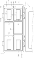
- the hairpin case 1 is divided into a plurality of storage parts by dividing the inside by a partition 4 that is long in the front-rear direction (vertical direction in FIG. 2) and a partition 4 that is long in the left-right direction (left-right direction in FIG. 2).
- the same or different hairpins 8 having a length substantially corresponding to each storage section 9 are stored in the left-right direction in the storage section 9.
- a case cover 7 is detachably attached to the case body 2, and a flange-like flange projecting outward on the outer surface of the right side wall 39 ⁇ / b> A in order to allow the hairpin 8 to be held and opened.
- An opener 3 is provided.
- a partition opener 6 is provided above the partition portion 4 so that the pin can be opened.
- the case main body 2 is a rectangular parallelepiped that is long in the left-right direction, and an upper portion is an opening 42.
- the interior of the case body 2 is partitioned into two front and rear directions by a partition 4 that is long in the left-right direction.
- the two partitioned spaces are divided into three storage portions 9 by two partitions 4 that are long in the front and rear direction. It is divided into. Therefore, the inside of the case body 2 is divided into six storage portions 9, and each storage portion 9 has its left and right directions so as to store various hairpins 8 such as oni pins, bob pins, screw pins, ball pins, and American pins. Are different in length.
- Each partition portion 4 is provided with a partition opener 6 that is thicker below the upper edge portion 5 at the upper portion thereof.
- This thick part has a double side wall structure, and the space 32 formed between the double side walls is open downward.
- the inside of the thick wall portion becomes hollow, that is, the side walls 11A and 11B forming the storage portions 9 are independently formed across the space, and the material forming the partition portion 4 is saved.
- the flange 13 protrudes outward over the entire circumference, and serves as a receiver for the case cover 7 when the case cover 7 is closed.
- a portion of the flange 13 corresponding to the outer surface of the right side wall 39A of the case body 2 is a flange opener 3 having a shape protruding outward.
- the flange opener 3 has two openings 10 in the front-rear direction in the flange portion so that one leg of the hairpin 8 can be inserted.
- the bridging portion 44 formed between the two openings has an effect of increasing the rigidity of the flange opener 3.
- the flange opener 3 has reinforcing triangular pieces 45 formed on both sides in the width direction and below the bridge portion 44. Since one side of the reinforcing triangular piece 45 is fixed to the outer surface of the right side wall 39A, the rigidity of the flange opener 3 is further increased and the leg of the hairpin 8 is easily opened. Even if a large force is applied to the flange opener 3 when the hairpin 8 is opened, there is no inconvenience such as the flange opener 3 being broken from the root because of the reinforcing triangular piece 45.
- a corner portion 17 ⁇ / b> A formed by the inner surface of the bottom wall 12 and the left and right side walls 11 ⁇ / b> A of the storage portion 9 has a substantially arcuate cross section.
- the corner portion 17B formed by the inner surface of the bottom wall 12 and the side wall 11B in the front-rear direction is also substantially arc-shaped in cross section. That is, the corner portions 17A and 17B of the bottom wall 12 of each storage portion 9 are outwardly rounded. Since the corner portion 17A on the inner surface of the bottom wall 12 of the storage portion 9 is rounded, the hairpin 8 can be smoothly taken out without stagnation in the corner portion 17A even if the hairpin 8 is reduced. Further, since the corner portion 17B is rounded, the hairpin 8 is pushed back by the corner portion 17B and is always located at the center portion of the storage portion 9, so that the removal is further facilitated.
- the roundness of the corner portion 17A is preferably larger than the roundness of the corner portion 17B in the left-right direction.
- a sheet-like magnet 23 which is a hairpin magnetized member 20 that attracts the hairpin 8 with a magnetic force, is attached in a band shape.
- the hairpins 8 are separated and magnetically attached one by one to the hairpin magnetized member 20 above the side wall 11 of the storage unit 9, and it is easy to take out the hairpin 8 and there is no need to search for the hairpin 8 with the fingertip. It becomes.
- a step is formed at the boundary between the bottom wall 12 and the sheet-like magnet 23, and the hairpin 8 may be caught there.
- a groove 25 having a depth substantially the same as the thickness of the sheet magnet 23 in the front-rear direction and having substantially the same width as the sheet magnet 23 is formed on the inner surface of the storage portion 9.
- the sheet-like magnet 23 may be attached in a band shape so as to fit into the groove portion 25.
- the sheet-like magnet 23 becomes substantially flush with the inner surface of the storage portion 9, and the hairpin 8 is not easily caught by the boundary.
- the affixing direction of the said hairpin magnetic adhesion member 20 is not limited to the front-back direction, and there is no problem even if it is the left-right direction. You may affix on the whole inner surface of the accommodating part 9.
- an anti-slip member 21 is provided on the bottom surface of the bottom wall 41 of the case body 2. That is, a frame portion 22 is formed at each of the four corners of the lower surface of the bottom wall 41 of the case body 2 in the front-rear and left-right directions, and a rubber 24 is attached to the inside of the frame portion. To protrude.
- the case main body 2 when the case main body 2 is placed at the placement position 48 such as on the wagon stand, the rubber 24 comes into contact with the placement position 48. Therefore, even when the hairpin 8 is taken out or the hairpin 8 is opened by the openers 3 and 6, the case body 2 does not slide on the placement position 48, and the operation can be performed smoothly. Further, when the case main body 2 is placed at a narrow space 48 such as on a wagon base, it is possible to prevent slipping from the case body 2.
- the anti-slip member 21 is not limited to the rubber 24, and there is no problem even if it is a suction cup. Further, the anti-slip member 21 may be provided at one central position of the bottom wall 41 as the pasting position.
- a case cover 7 that opens and closes a case opening 42 of the case body 2 is attached to the case body 2 by two hinges 27 so as to be rotatable.
- the hinge 27 includes a hinge receiving portion 50 provided on the case body 2 and a hinge piece 51 provided on the case cover 7.
- the hinge receiving portion 50 is provided at two locations separated from each other so that the hinge receiving portion 50 is located near both ends of the case opening 42 in the case body 2.
- Each hinge receiving portion 50 has a pair of shaft boss portions 53, 53 that protrude outward from the case body 2 with the fitting space 52 in the center.
- the shaft boss portions 53 and 53 are formed with shaft holes 55 and 55 in which the respective shaft centers coincide with each other (surfaces facing the fitting space 52) facing each other.
- the shaft boss portion 53 and the shaft hole 55 are arranged on the same axis parallel to the side direction of the side portion where the hinge receiving portion 50 is provided, and the axis parallel to the side direction swings relative to the case body 2. It becomes the swinging shaft at the time.
- a hinge piece 51 into which the above-described hinge receiving portion 50 can be fitted is formed on one side portion of the case cover 7.
- the hinge piece 51 is provided on one side of the case cover 7 at two locations at the same interval as the hinge receiving portion 50.
- the hinge piece 51 has a shaft support portion 57 that protrudes outward from the case cover 7.
- the shaft support portion 57 is formed to have a size that can be fitted into the fitting space 52 formed in the hinge receiving portion 50, and the opposite end surfaces of the shaft support portion 57 (the respective shaft bosses of the hinge receiving portion 50).
- Oscillating shafts 58 and 58 that are fitted to the shaft holes 55 and 55 so as to be rotatable in a state in which the respective shaft centers coincide with each other are formed so as to protrude from the surface facing the portions 53 and 53.
- the hinge receiving portion 50 is disposed at a height that can hold the case cover 7 opened from the case body 2 above the case installation surface, in other words, above the bottom surface of the case.
- the shaft boss portions 53 and 53 are formed with notches 60 and 60 that penetrate the shaft holes 55 and 55 downward. These notches 60, 60 are formed so that the opening width is the same or narrower than the hole diameter (diameter) of the shaft holes 55, 55 even at the widest opening width, and the opening width becomes narrower downward.
- the swing shafts 58 and 58 do not open the notches 60 and 60.
- the shaft holes 55 and 55 are engaged and held so as not to be able to escape while maintaining a rotatable state in the shaft holes 55 and 55. That is, the case cover 7 can swing and open with respect to the case body 2.
- hooks 26 for connecting and fixing the case body 2 and the case cover 7 when the cover is closed are provided at two positions on the front left and right sides of the case body 2.
- Protrusions 30 on which the hooks 26 are hooked are provided at two positions on the front surface of the case cover.
- the case cover 7 is provided with outer peripheral ribs 62 so as to surround the outer peripheral portion thereof.
- the outer peripheral rib 62 surrounds the outer peripheral portion of the case opening 42 when the case cover 7 is put on the case opening 42 of the case main body 2.
- the outer peripheral rib 62 surrounds the outer peripheral portion of the bottom wall 41 when the case cover 7 is removed from the case main body 2 and turned over and laid under the bottom wall 41 of the case main body 2.
- the inner surface of the case cover 7 is formed with a restricting portion 15 that protrudes toward the inside of the case body 2 as a state when it is put on the case opening 42 of the case body 2. More specifically, in order to prevent a gap from being generated between the upper edge portion 5 of the partition portion 4 and the inner surface of the case cover 7, the upper edge portion 5 is interposed between the protrusions by two protrusions.
- a groove portion 28 is formed so as to be fitted to each other, and the restricting portion 15 is constituted by the protrusions (groove portion 28) on both sides.
- the case openings 42 (all the storage portions 9) can be closed and the gap formed by the upper edge portion 5 and the inner surface of the case cover 7 can be eliminated. it can. Therefore, even when the case body 2 is moved around, the hairpin 8 does not jump out of the case body 2 and does not fall apart, and the movement (mixing) of the hairpin 8 between the storage units 9 is also prevented. Can be prevented. Further, the restricting portion 15 functions as a reinforcing rib provided on the inner surface of the case cover 7 and increases the rigidity of the case cover 7.
- the upper edge portion 5 that fits into the groove portion 28 is preferably attached with a non-slip rubber 29 at substantially the same height as the case opening 42 on both sides thereof.
- the anti-slip member 21 is provided on the bottom surface of the bottom wall 41 of the case body 2, and the anti-slip member 21 has the case cover 7 removed from the case body 2 and turned over.
- the restricting portion 15 is formed to have a thickness equal to or greater than the height of the restricting portion 15 protruding from the bottom surface of the bottom wall 41 of the case body 2.
- the thickness of the anti-slip member 21 refers to the vertical dimension from the lower surface of the bottom wall 41 of the case body 2 to the lower surface of the anti-slip member 21. Therefore, when the bottom wall 41 is a flat surface, it corresponds to the thickness of the rubber 24. However, when the bottom wall 41 is thickened at the position where the rubber 24 is applied to make the bottom wall 41 bulge downward, this bulging dimension. And the thickness of the rubber 24.
- the hairpin case 1 of the present embodiment described above is made of plastic or the like, and the case main body 2 and the case cover 7 are respectively injection molded. However, it is not limited to this form, and when strength is required, there is no problem even if it is formed by bending and welding a steel plate or the like.
- the hairpins 8 are separated in advance and individually stored in the storage units 9, and the hairpin case 1 is placed at a placement position 48 such as on a wagon table.
- the case cover 7 is detachable from the case main body 2, the case cover 7 is removed and, for example, the hairpin 8 is placed in a region partitioned by the restriction portion 15 on the inner surface of the case cover 7. It can also be used.
- the case cover 7 is opened so as to project to the side of the case main body 2, and the case cover 7 is removed. Press down. By this pressing, the swing shafts 58 and 58 of the hinge piece 51 provided on the case cover 7 are moved downward from the shaft holes 55 and 55 of the hinge receiving portion 50 provided on the case body 2 through the notches 60 and 60.
- the case cover 7 can be easily detached from the case main body 2 as shown in FIG.
- the case cover 7 Since the hinge receiving portion 50 of the case body 2 holds the case cover 7 above the upper surface (case installation surface) of the placement position 48, the case cover 7 is in an open state (before pressing downward). ), The case cover 7 is slanted with the side opposite to the hinge piece 51 placed in contact with the upper surface of the position 48. For this reason, when the case cover 7 is pressed downward, a downward rotational moment with the contact point with the upper surface of the placement position 48 as a fulcrum is efficiently generated in the case cover 7. The downward escape of 58 and 58 can be performed very easily. That is, the case cover 7 can be easily removed from the case body 2.
- the hairpin case 1 is configured such that the bottom wall 41 of the case main body 2 fits inside the case cover 7 (inner region surrounded by the outer peripheral rib 62), as shown in FIG. 7 is placed on the placing position 48 so that the inner surface faces upward (turned over), and the case body 2 is placed so as to be fitted from above (the case cover 7 is placed under the bottom wall 41 of the case body 2). Can be laid).
- the case cover 7 can be placed in the bottom area of the case body 2 so that it can be installed (included), so that the entire area of the hairpin case 1 on the placement position 48 can be made compact. Can be suppressed. That is, it is possible to prevent the hairpin case 1 from interfering with other work (such as putting in and out of hairdressing and beauty tools). Moreover, since the position where the case main body 2 is placed increases as much as the case cover 7 is overlapped, the hairpin 8 can be taken out more easily. In this case, since the case cover 7 may slide on the placement position 48, it is preferable to provide the anti-slip member 21 on the upper surface of the case cover 7 as shown by a two-dot chain line in FIGS.
- the anti-slip member 21 is disposed so as not to contact the restricting portion 15 of the case cover 7 and has a thickness equal to or greater than the protruding height of the restricting portion 15. No backlash occurs during this period, and a stable mounting state can be obtained.
- the finger is moved so as to crawl the inner surface of each storage portion 9 in the front-rear direction so that the desired hairpin 8 is scooped.
- the corner portions 17A and 17B of the bottom wall 12 of each storage portion 9 are outwardly rounded. According to this, since the corner portion 17 is rounded, the hairpin 8 can be smoothly taken out without stagnation in the corner portion 17A even if the hairpin 8 is reduced. Further, due to the roundness of the corner portion 17B, the hairpin 8 is pushed back by the corner portion 17B and is always located at the center portion of the storage portion 9, and the removal thereof is further facilitated.
- a sheet-like magnet 23 is attached in a strip shape in the front-rear direction on the inner surface of each storage unit 9.
- the hairpins 8 are separated and magnetically attached one by one above the side wall 11 of the storage unit 9, so that it is easy to take out the hairpin 8 and it is not necessary to search for the hairpin 8 with the fingertip.
- the leg can be easily opened by being inserted into the partition opener 6 from above.
- hairpins 8 With their short legs upward and sandwiched between the flange openers 3. By rotating these hairpins 8 upward, the short legs are formed.
- the hairpin 8 can be greatly opened by being inserted into the opening 10. That is, the opening of the hairpin 8 can be easily performed by these operations in the openers 3 and 6.
- the hairpin 8 there is also a pin-linked product 35 that is mounted by sandwiching a predetermined number of hairpins with a tape of a predetermined length.
- the pin is rounded and stored in the storage unit 9.
- the pin-connected product 35 is taken out, and a plurality of hairpins 8 are taken out from the tape, and inserted between the flange opener 3 and the partition opener 6. It becomes possible.
- the case body 2 can be considered to slide on the placement position 48.
- the anti-slip member 21 is provided on the bottom surface of the bottom wall 41 of the case body 2, the case body 2 is prevented from sliding on the placement position 48.
- the flange opener 3 is not provided only on the outer side of the right side wall 39 ⁇ / b> A of the case body 2, but may be provided on the entire circumference of the case body side wall 39. Further, it may be provided on two or three surfaces of the side wall 39 of the case body 2. In consideration of a left-handed user, it is preferably provided outside the left side wall 39B.
- the partition openers 6 do not have to be provided in all the partition parts 4, and may be provided only in the front-rear direction partition part 4 or only in the left-right direction partition part 4. There is no problem even if it is provided in only one partition in the case body 2.
- the hairpin opener is not limited to the partition opener 6 and the flange opener 3, and there is no problem even if the case cover 7 is formed as a single plate and the side end thereof is used as the opener.
- the hairpin case 1 of this embodiment is provided with both the flange opener 3 and the partition opener 6, it does not necessarily need to have both, and even if it is the structure which has only one of them, there is no problem. There is no. Further, the storage unit 9 has different lengths in the left-right direction so that various hairpins can be stored, but it may have the same length in the left-right direction. Conversely, there is no problem even if the lengths are different in the vertical direction.
- the partition part 4 which forms the accommodating part 9 does not need to have a double side wall structure, and may be a single plate with a non-slip rubber 29 attached to both sides of the upper edge part 5.
- One plate may be provided with protrusions on both sides of the upper edge portion 5.
- the restriction portion 15 formed on the inner surface of the case cover 7 does not need to be the ridge groove portion 28, and there is no problem even if it is a single ridge that is attached to the upper edge portion 5. In other words, even the protrusion restricting portion 15 can restrict the movement of the hairpin 8 between the storage portions 9.
Landscapes
- Purses, Travelling Bags, Baskets, Or Suitcases (AREA)
Abstract
La présente invention se rapporte à des épingles à cheveux qui peuvent être insérées et stockées ou être stockées avec les pointes ouvertes dans un corps de boîte principal qui reçoit les épingles à cheveux et facilite la manipulation des épingles à cheveux. Dans le corps de boîte principal (2) dont l'intérieur est divisé par des séparations (4) dans le sens avant-arrière et/ou la direction gauche-droite afin de former de multiples réceptacles (9), on agence un dispositif d'ouverture de bride en forme de bride (3) qui fait saillie vers l'extérieur depuis la surface externe d'une paroi latérale (39) et qui permet la fixation et l'ouverture des pointes des épingles à cheveux (8) et/ou un dispositif d'ouverture de séparation (6) est agencé au niveau de la partie supérieure d'une séparation (4) de sorte à être plus épais au niveau de la partie inférieure qu'au niveau du bord supérieur (5).
Priority Applications (1)
| Application Number | Priority Date | Filing Date | Title |
|---|---|---|---|
| PCT/JP2010/073075 WO2012086020A1 (fr) | 2010-12-22 | 2010-12-22 | Boîte d'épingles à cheveux |
Applications Claiming Priority (1)
| Application Number | Priority Date | Filing Date | Title |
|---|---|---|---|
| PCT/JP2010/073075 WO2012086020A1 (fr) | 2010-12-22 | 2010-12-22 | Boîte d'épingles à cheveux |
Publications (1)
| Publication Number | Publication Date |
|---|---|
| WO2012086020A1 true WO2012086020A1 (fr) | 2012-06-28 |
Family
ID=46313324
Family Applications (1)
| Application Number | Title | Priority Date | Filing Date |
|---|---|---|---|
| PCT/JP2010/073075 Ceased WO2012086020A1 (fr) | 2010-12-22 | 2010-12-22 | Boîte d'épingles à cheveux |
Country Status (1)
| Country | Link |
|---|---|
| WO (1) | WO2012086020A1 (fr) |
Citations (2)
| Publication number | Priority date | Publication date | Assignee | Title |
|---|---|---|---|---|
| JPH03100876U (fr) * | 1989-11-28 | 1991-10-22 | ||
| JP2003235643A (ja) * | 2002-02-21 | 2003-08-26 | Goriki Kogyo:Kk | ヘアピンケース |
-
2010
- 2010-12-22 WO PCT/JP2010/073075 patent/WO2012086020A1/fr not_active Ceased
Patent Citations (2)
| Publication number | Priority date | Publication date | Assignee | Title |
|---|---|---|---|---|
| JPH03100876U (fr) * | 1989-11-28 | 1991-10-22 | ||
| JP2003235643A (ja) * | 2002-02-21 | 2003-08-26 | Goriki Kogyo:Kk | ヘアピンケース |
Similar Documents
| Publication | Publication Date | Title |
|---|---|---|
| JP6465990B2 (ja) | 爪切り | |
| KR100553981B1 (ko) | 루프 요소 및 후크 요소를 갖는 경첩을 포함하는 박스 | |
| JP2014128851A (ja) | 工具収容ケース、及び、サブケース | |
| JP3229941U (ja) | エコポータブル食器 | |
| JP5814076B2 (ja) | 化粧料容器 | |
| US8985378B2 (en) | Cosmetic compact | |
| US8079469B2 (en) | Case for holding a hand tool | |
| JP3894808B2 (ja) | ヘアピンケース | |
| WO2012086020A1 (fr) | Boîte d'épingles à cheveux | |
| KR200440773Y1 (ko) | 휴대용 악세사리 및 미용기구 보관케이스 | |
| JP5555556B2 (ja) | 化粧料容器 | |
| JP5502598B2 (ja) | 化粧料容器 | |
| KR200365005Y1 (ko) | 화장솔 보관 케이스 | |
| JPH0231052Y2 (fr) | ||
| JP3100876U (ja) | ヘアピンケース | |
| JP2010184720A (ja) | スライド式容器 | |
| JP6496766B2 (ja) | 歯間ブラシ用パッケージ | |
| JPH0724130U (ja) | ヘアブラシ | |
| JP2015226724A (ja) | 化粧用コンパクトケース | |
| JP7854652B2 (ja) | コンパクト容器 | |
| JP5281348B2 (ja) | 化粧料容器 | |
| JP4526798B2 (ja) | ヘアピンケースホルダ | |
| JP4659392B2 (ja) | 化粧料容器 | |
| JP5230321B2 (ja) | 化粧料容器 | |
| JP3188730U (ja) | ボックスの持ち手 |
Legal Events
| Date | Code | Title | Description |
|---|---|---|---|
| 121 | Ep: the epo has been informed by wipo that ep was designated in this application |
Ref document number: 10861179 Country of ref document: EP Kind code of ref document: A1 |
|
| NENP | Non-entry into the national phase |
Ref country code: DE |
|
| 122 | Ep: pct application non-entry in european phase |
Ref document number: 10861179 Country of ref document: EP Kind code of ref document: A1 |
|
| NENP | Non-entry into the national phase |
Ref country code: JP |