WO2012086077A1 - Fermeture à glissière - Google Patents
Fermeture à glissière Download PDFInfo
- Publication number
- WO2012086077A1 WO2012086077A1 PCT/JP2010/073423 JP2010073423W WO2012086077A1 WO 2012086077 A1 WO2012086077 A1 WO 2012086077A1 JP 2010073423 W JP2010073423 W JP 2010073423W WO 2012086077 A1 WO2012086077 A1 WO 2012086077A1
- Authority
- WO
- WIPO (PCT)
- Prior art keywords
- slider
- fastener
- tape
- slide fastener
- stopper
- Prior art date
- Legal status (The legal status is an assumption and is not a legal conclusion. Google has not performed a legal analysis and makes no representation as to the accuracy of the status listed.)
- Ceased
Links
Images


Classifications
-
- A—HUMAN NECESSITIES
- A44—HABERDASHERY; JEWELLERY
- A44B—BUTTONS, PINS, BUCKLES, SLIDE FASTENERS, OR THE LIKE
- A44B19/00—Slide fasteners
- A44B19/24—Details
- A44B19/36—Means for permanently uniting the stringers at the end; Means for stopping movement of slider at the end
-
- A—HUMAN NECESSITIES
- A44—HABERDASHERY; JEWELLERY
- A44B—BUTTONS, PINS, BUCKLES, SLIDE FASTENERS, OR THE LIKE
- A44B19/00—Slide fasteners
- A44B19/24—Details
- A44B19/38—Means at the end of stringer by which the slider can be freed from one stringer, e.g. stringers can be completely separated from each other
- A44B19/384—Separable slide fasteners with quick opening devices
Definitions
- the present invention relates to a slide fastener capable of separating left and right fastener stringers by disengaging the left and right element rows from the weakened portion, in which a weakened portion in which the engagement force is locally reduced is arranged in the element row. .
- Patent Document 1 discloses a slide fastener that can quickly disengage the left and right element rows to separate the left and right fastener stringers. Such a slide fastener is sometimes referred to as an emergency opening fastener and has been used for a life jacket or the like.
- the tape length direction of the fastener tape is defined as the front-rear direction, and in particular, the direction in which the slider is slid so as to engage the left and right element rows is the front, and the engagement of the element rows is released.
- the direction in which the slider slides is the rear.
- the tape width direction of the fastener tape is defined as the left-right direction, and the left side when the slide fastener is viewed from the front side is the left side, and the right side is the right side.
- the tape front and back direction of the fastener tape is defined as the vertical direction, and the side on which the slider handle is arranged is the upper side with respect to the tape surface of the fastener tape, and the opposite side is the lower side.
- the slide fastener 90 described in Patent Document 1 is slidable along a pair of left and right fastener stringers 91 in which an element row 93 is formed on the side edges of the left and right fastener tapes 92 and the element row 93.
- an open / close insert 96 is an open / close insert 96.
- a core string portion 92a is disposed on the opposing tape side edges of the left and right fastener tapes 92, and a plurality of fastener elements 93a are provided on the tape side edge portion of the fastener tape 92 including the concentric string portions 92a.
- the left and right element rows 93 are provided with weak portions 93b by gaps formed by intentionally removing a predetermined number of fastener elements 93a.
- the right fastener stringer 91 is provided with a stopper 95 on the front end side of the element row 93, but the fastener 95 is not provided on the front end side of the element row 93 in the left fastener stringer 91. . Further, the front end of the left element row 93 is located behind the front end of the right element row 93, and the left element row 93 is formed shorter than the right element row 93.
- the fastener element 93a disposed on the most front end side of the left element row 93 (hereinafter, this fastener element is referred to as a front end element) is stopped by sliding the slider 94 to the front end position where it abuts against the stopper 95.
- a part of the front end element 93a is accommodated in the element guide path of the slider 94.
- the opening / closing insert 96 in the slide fastener 90 includes a butterfly pin 96a fixed along the element row 93 to the rear end portion of the left fastener stringer 91 and an element row 93 at the rear end portion of the right fastener stringer 91.
- a box rod 96b fixed so as to oppose the butterfly rod 96a along with the box rod 96b, and a box body 96c disposed integrally with the box rod 96b at the lower end of the box rod 96b.
- the left and right element rows 93 are engaged by sliding the slider 94 forward toward the stopper 95, and the slider 94 is brought into contact with the stopper 95.
- the left and right fastener stringers 91 can be completely closed.
- the slide fastener 90 of Patent Document 1 is provided with a fragile portion 93b in a part of the left and right element rows 93. Therefore, the slide fastener 90 receives a lateral pulling force that strongly pulls the left and right fastener stringers 91 away from each other. In this case, the fragile portion 93b is opened, the meshing is released from the left and right fastener elements 93a adjacent to the fragile portion 93b in the longitudinal direction of the tape length direction, and the left and right element rows 93 are separated.
- the left and right element rows 93 are released to the front end, the left front end element 93a, which is partially accommodated in the element guide path of the slider 94, is pulled out from the rear opening of the slider 94.
- the butterfly stick 96a is extracted from the box 96c. Thereby, the left and right fastener stringers 91 can be completely separated.
- the slide fastener 90 of Patent Document 1 when the left and right element string 93 is separated from the fragile portion 93b and the left and right fastener stringers 91 are completely separated as described above, the slide fastener 90 is opened by sliding the slider 94. Compared to the above, the left and right fastener stringers 91 can be easily and quickly pulled apart. For this reason, the slide fastener 90 of Patent Document 1 is particularly effectively used for fastener-attached products such as life jackets that require a quick response in an emergency, for example.
- Patent Document 2 Japanese Utility Model Publication No. 4-84313 describes that a slide fastener is used by attaching it to training pants.
- the training pants described in Patent Document 2 are configured such that slide fasteners are attached to the left and right leg portions from the upper end portion on the waist side to the lower end portion on the hem side of the training pants. According to such training pants of Patent Document 2, the training pants are removed from the form of the pants by sliding the slide fastener sliders attached to the left and right legs to separate the fastener stringers of each slide fastener. It becomes possible to open into two parts, a front piece and a back piece.
- the front piece and the back piece opened in this way are connected by sliding the slide fastener sliders arranged on the left and right legs and closing the left and right fastener stringers again, so that the training pants Can be returned to its original pant form.
- the training pants of Patent Document 2 having such a configuration can be worn or taken off in the same manner as conventional general training pants when the left and right slide fasteners are closed.
- the training pants can be easily worn even while wearing competition shoes or spikes by separating the left and right fastener stringers of the slide fastener into a front piece and a back piece. It is possible to undress.
- the slide fastener opening / closing inserts are arranged at the lower end on the hem side and the fasteners are arranged on the upper end on the waist side. Is done. For this reason, when the shape of the pants is held by meshing the element rows of the slide fastener, the slider of the slide fastener is disposed on the waist portion that contacts the stopper.
- the front end element 93a itself housed in the element guide path of the slider 94 becomes the flange of the slider 94. Receives a large force (load) locally. At this time, the contact area between the front end element 93a and the fastener tape 92 is small, and the fixing strength of the front end element 93a to the fastener tape 92 is never high. Therefore, when the front end element 93a receives a large stress from the flange of the slider 94, the front end element 93a is removed from the fastener tape 92, and the closed state of the fastener stringer 91 cannot be maintained.
- the front end element 93a receives a large load from the flange when the front end element 93a is hooked on the flange of the slider 94. There was a problem that the front end element 93a was easily removed from the fastener tape 92 and dropped off.
- the present invention has been made in view of the above-described conventional problems, and a specific object thereof is that even if the slider is stopped at the end position on the upper stopper side, The closed state of the fastener stringer can be stably maintained, and the left and right fastener stringers can be separated without damaging the components of the slide fastener when the left and right fastener stringers are separated from the fragile portion. It is to provide a possible slide fastener.
- a slide fastener provided by the present invention has, as a basic structure, a pair of left and right elements in which element rows are attached to opposing tape side edges of a pair of first and second fastener tapes.
- the first and second fastener stringers a slider slidable along the element row, a stopper disposed on one end side of the element row in the first fastener stringer, and the element row, At least one weakened portion in which the meshing force of the left and right element rows is locally reduced or eliminated, and the slider has a substantially Y-shaped element guide path between the upper and lower blades, A tape insertion gap for the first and second fastener tapes is formed at a side edge of the slider, and the element row in meshing state is separated from the weakened portion.
- the first and second fastener stringers are slide fasteners that can be separated from each other, and a side punching prevention portion is arranged on one end side of the element row in the second fastener stringer, In order to prevent the second fastener tape from being pulled out from the element guide path of the slider through the tape insertion gap when the first and second fastener stringers in the closed state receive a lateral pulling force. It has a thickness for preventing lateral punching that has a dimension in the tape front and back direction that is larger than the interval between the tape insertion gaps.
- the main feature is to have at least one narrow portion.
- the narrow portion is configured by providing a slit in the side-cut preventing portion.
- the slit is preferably arranged in the tape width direction from the side edge on the inner side of the tape in the transverse prevention portion, and further, the slit width at the opening side end of the slit is narrowed. It is particularly preferable.
- the slit may be arranged in the tape width direction from an end edge of the side-cut preventing portion on the side facing the stopper.
- a core string portion is disposed on a tape side edge of the first and second fastener tapes, and at least a part of the core string portion disposed on the second fastener tape It is preferable that it is embedded in the prevention part.
- the length dimension of the cross-out preventing portion is set to be larger than the interval from the rear end position of the guide column to the rear opening position in the slider, and the slider stopped at the end portion on the stopper side.
- the size is set so as to be accommodated in the element guide path.
- the narrow width portion may be configured such that a concave fitting portion is arranged on the lateral punching prevention portion.
- the dimension in the tape width direction of the narrow width portion in the lateral punching prevention portion is set to be smaller than the dimension in the tape front and back direction of the lateral punching prevention portion.
- the upper and lower flanges of the slider may be parallel to each other on the rear opening side of the slider, and may extend from one end of the parallel portion, and may be spaced from the left and right upper and lower flanges.
- the taper at the inclined portion of the upper and lower flanges with respect to the slider stopped at the end on the fastener side. It is preferable to be disposed within the range in the length direction.
- the said horizontal punching prevention part in the slide fastener of this invention has a plane in the side surface facing the said fastener.
- the side-cut prevention portion has a protruding portion that protrudes toward the first fastener tape, and a pseudo element is provided between the stopper and the element row in the first fastener tape.
- the pseudo element extends from the body portion between the side portion preventing portion of the second fastener stringer and the element row, and is fixed to the first fastener tape. It is preferable to have a head that can slidably contact the protruding portion of the pull-out preventing portion.
- the stopper has a stopper portion having a dimension in the tape width direction larger than the insertion width between the guide column and the upper and lower flanges in the slider, and the stopper portion is the slider of the slider.
- the slider locking portion has a slider locking portion that contacts the guide column and locks the slider, and is configured to be elastically deformable in the tape width direction.
- the slide fastener according to the present invention is configured such that a stopper is disposed at one end portion of one first fastener stringer, and a lateral punching prevention portion is disposed at one end portion of the other second fastener stringer. At least a part of the punching prevention part has a thickness for preventing lateral punching having a dimension in the tape front and back direction larger than the interval of the tape insertion gap of the slider.
- Such a slide fastener of the present invention has the above-described thickness for preventing the lateral punching when the slider is slid to the front end position where it abuts the stopper and the left and right first and second fastener stringers are closed.
- a side-out preventing portion is accommodated in the element guide path of the slider. For this reason, even if these first and second fastener stringers receive a lateral pulling force in the closed state of the first and second fastener stringers, the second fastener tape is inserted into the tape from the element guide path of the slider by the lateral punching prevention portion. Since it can be prevented from being pulled out through the gap, the left and right element rows are not separated, and the closed state of the first and second fastener stringers can be stably maintained.
- the horizontal hole prevention part should just be provided with the thickness of the above-mentioned horizontal hole prevention in at least one part of the horizontal hole prevention part, and the horizontal hole prevention part of this invention is the above-mentioned horizontal hole prevention part, for example A main body portion having a thickness of 1 mm and a tape front and back direction dimension that is smaller than the interval between the tape insertion gaps of the slider and extending from the main body portion (for example, a fin portion shown in a later-described modification) ).
- the present invention includes a case where the dimension of the side-by-side prevention part in the tape front and back direction is not set constant throughout the side-by-side prevention part.
- the horizontal punching prevention portion in the present invention has at least one narrow width portion having a reduced size in the tape width direction in a portion having a thickness for preventing horizontal punching, the horizontal punching prevention portion is provided. It can be easily elastically deformed so as to be bent in the tape width direction. As a result, when the first and second fastener stringers are closed, the left and right element rows are separated from the fragile portions provided in the element rows even if the transverse prevention portion is accommodated in the element guide path of the slider. In some cases, by elastically deforming the lateral punching preventing portion, the lateral punching preventing portion can be smoothly pulled out from the element guide path of the slider, and interference between the lateral punching preventing portion and the slider can be minimized. Accordingly, the left and right first and second fastener stringers can be smoothly pulled apart.
- the lateral punching prevention portion is not constituted by a single member, and a predetermined interval is provided at the tape side edge portion of the second fastener tape. It is also conceivable to form a plurality of independent small resin molded bodies (that is, in a form in which the narrow width portion of the lateral punching prevention portion in the present invention is completely divided).
- the horizontal punching prevention part is constituted by a plurality of independent small resin moldings
- the horizontal punching prevention part is more in the tape width direction than when the horizontal punching prevention part is constituted by a single member.
- the adhesive strength with the 2nd fastener tape in each resin molded object falls remarkably.
- the side-cut preventing portion by forming the side-cut preventing portion with a single member, the fixing strength of the side-cut preventing portion with respect to the second fastener tape is greatly increased, and the side-cut preventing portion can be removed from the second fastener tape. Can be effectively prevented from falling off.
- the narrow width portion is configured by arranging a slit in the lateral punching prevention portion.
- the slit is formed from a side edge on the inner side of the tape in the lateral punching prevention portion. It is arranged in the tape width direction.
- a deformation limiting mechanism described later can be stably configured.
- the protruding portions on the opening side end side of the slit in the lateral punching preventing portion collide with each other, so that the lateral punching preventing portion can be further elastically deformed further. Can be limited.
- the horizontal punching prevention portion when the left and right element rows are separated from the fragile portion and the horizontal punching prevention portion is pulled out from the slider element guide path through the rear opening, the horizontal punching prevention portion is elastically deformed. While being pulled out.
- the slit width at the opening side end portion of the slit is narrowed, when the side punching prevention portion is elastically deformed, the slit on the opening side end portion side of the side punching prevention portion is projected.
- the opening side end of the slit can be closed by bringing the portions into contact with each other, or the protruding portions on the opening side end side of the slit can be brought close to each other to further reduce the slit width of the opening side end. For this reason, when pulling out the horizontal punching prevention part from the element guide path of the slider, the flange of the slider can be effectively prevented from being caught by the slit of the horizontal punching prevention part, and the horizontal punching prevention part can be pulled out more smoothly. it can.
- the slit is an edge on the side facing the stopper in the lateral punching prevention portion.
- the laterally preventing portion is easily elastic in the tape width direction when the first and second fastener stringers are separated from the weakened portion. Can be deformed.
- a core string portion is arranged on the tape side end edges of the first and second fastener tapes, and at least a part of the core string portion arranged on the second fastener tape is embedded in the lateral punching prevention portion.
- the core string portion of the second fastener tape can be protected by the side-cut prevention portion, so that the core string portion is prevented from being damaged or damaged due to direct contact with the slider, and the durability of the slide fastener. Can be improved.
- the side-cut preventing part embeds at least a part of the core string part in this way, the fixing strength between the side-cut preventing part and the second fastener tape can be increased. For this reason, for example, when the first and second fastener stringers receive a lateral pulling force in the closed state, even if the lateral punching prevention portion receives a large load from the flange of the slider, the lateral punching prevention portion is removed from the second fastener tape. It is possible to effectively prevent it from being damaged.
- the length dimension of the lateral punching prevention portion is set to be larger than the interval from the rear end position of the guide column to the rear opening position in the slider, and stops at the end portion on the fastener side.
- the slider is set to a size that can be accommodated in the element guide path.
- the first and second fasteners in the closed state are set in such a manner that the dimension in the tape length direction of the lateral punching prevention portion is set larger than the interval from the rear end position to the rear opening position of the guide pillar in the slider. Even if the stringer receives a lateral pulling force, it is possible to more reliably prevent the lateral pulling prevention portion from being pulled out from the slider element guide path through the tape insertion gap, and the closed state of the first and second fastener stringers is more stable. Can be maintained.
- the horizontal punching prevention part has the dimensions in the tape length direction as described above, the core string part can be more stably protected by the horizontal punching prevention part, and the horizontal punching prevention part is in the tape length direction. Therefore, since the contact area with the second fastener tape is increased, it is possible to increase the fixing strength of the lateral punching preventing portion with respect to the second fastener tape. In this case, it is preferable that the lateral punching prevention portion is formed longer in the tape length direction than the flange of the slider.
- the length dimension of the cross-cut prevention portion is set to a size that can be accommodated in the element guide path with respect to the slider stopped at the end portion on the stopper side, so that the slider is positioned at the end on the stopper side.
- the side-cut preventing portion can be accommodated in the slider so that it cannot be seen, so that the appearance of the slide fastener can be improved.
- the slide fastener of this invention has a deformation
- the horizontal punching prevention portion is greatly curved, and the upper and lower flanges of the slider (particularly, the flange portion (hereinafter referred to as the flange portion that is disposed on the shoulder opening side of the upper and lower flanges)
- the flange portion is referred to as an inclined portion of the upper and lower flanges))
- a large load may be applied to the inclined portion of the flange from the side wall preventing portion.
- the slide fastener of the present invention has the deformation limiting mechanism as described above, when the first and second fastener stringers in the closed state receive a lateral pulling force, they are prevented from being pulled out. Even if the part is elastically deformed to the upper and lower flange side of the slider, it can be prevented from contacting the inclined part of the upper and lower flange, or even if contacted, the load applied to the inclined part of the upper and lower flange can be reduced. . As a result, the slider can be prevented from sliding in the separation direction of the element row against the user's intention, and the state where the first and second fastener stringers are closed can be stably maintained.
- the narrow width portion may be configured not by the slit as described above but by having a concave fitting portion arranged in the side-cut preventing portion. Even in the case where the narrow portion of the lateral punching prevention portion is configured in this way, when the first and second fastener stringers are separated from the fragile portion, the lateral punching prevention portion can be easily arranged in the tape width direction. It can be elastically deformed.
- the tape width direction dimension of the narrow width portion in the lateral punching prevention portion is set smaller than the dimension of the lateral stripping prevention portion in the tape front and back direction.
- the upper and lower flanges of the slider have a parallel portion arranged parallel to each other on the rear opening side of the slider, and an inclined portion that gradually increases the distance between the left and right upper and lower flanges toward the shoulder opening.
- the narrow width portion of the transverse prevention portion is disposed within the range of the tape length direction in the inclined portion of the upper and lower flanges with respect to the slider stopped at the end on the stopper side.
- the lateral punching preventing portion has a flat surface on the side surface facing the fastener.
- the side-cut preventing portion has a protruding portion that protrudes toward the first fastener tape.
- a pseudo element is arranged between the fastener and the element row in the first fastener tape, and the pseudo element includes a trunk portion fixed to the first fastener tape, and a horizontal extraction of the other second fastener stringer from the trunk portion.
- the head portion extends between the prevention portion and the element row, and has a head portion that can be slidably brought into contact with the protruding portion of the horizontal penetration prevention portion.
- the slide fastener receives a lateral pulling force in a state where the slider is stopped at the end position on the stopper side, it is simulated that the lateral punching prevention portion is pulled out from the element guide path of the slider through the rear opening. It can prevent with an element and can prevent that the element row
- the pseudo element when separating the left and right element rows from the fragile part and pulling out the horizontal punching prevention part from the rear opening of the slider, the pseudo element is pressed by the protruding part of the horizontal punching prevention part, so that the pseudo element is relatively It is possible to secure a gap through which the crossing prevention portion can pass at the rear opening of the slider. As a result, it is possible to smoothly pull out the lateral punching prevention portion from the element guide path of the slider through the rear opening.
- the stopper has a stopper having a dimension in the tape width direction larger than the insertion width between the guide column and the upper and lower flanges in the slider, and the stopper is the slider. It has a slider locking portion that contacts the guide column and locks the slider. The slider locking portion is configured to be elastically deformable in the tape width direction.
- the slider locking portion of the stopper abuts against the guide column of the slider, and the slider Can be stably held at the stop position. Accordingly, when the end portion on the stopper side of the slide fastener receives a lateral pulling force in a state in which the first and second fastener stringers are closed, a force that causes the slider to slide in the separation direction of the element row works. Even so, the slider can be locked by the slider locking portion to prevent the slider from sliding.
- the guide pillar presses the slider locking portion and elastically deforms the slider locking portion, thereby releasing the slider holding state by the slider locking portion and smoothly sliding the slider in the element row separating direction.
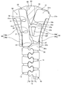
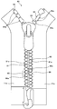
- FIG. 1 is a front view schematically showing a slide fastener according to an embodiment of the present invention.
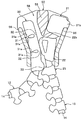
- FIG. 2 is a schematic view showing a state in which the slider is held by a stopper in the slide fastener.
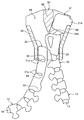
- FIG. 3 is a schematic diagram showing a state in which the left and right element rows are separated when the element row of the slide fastener is separated from the fragile portion.
- FIG. 4 is a schematic diagram showing a state in which the slider sliding contact body is pulled out from the rear opening of the slider.
- FIG. 5 is a schematic diagram showing a state in which the slider sliding contact body is pulled out from the rear opening of the slider.
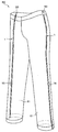
- FIG. 6 is a perspective view showing training pants to which the slide fastener is sewn.
- FIG. 7 is a schematic diagram showing a modification of the slider sliding contact body.
- FIG. 8 is a front view schematically showing a slide fastener according to a modification of the present invention.
- FIG. 9 is a front view schematically showing a conventional
- a fastener is arranged on the right fastener stringer and a slide fastener is formed by arranging a lateral punching prevention portion on the left fastener stringer.
- the right fastener stringer It is also possible to arrange a slide fastener by arranging a stopper on the left fastener stringer and arranging a horizontal prevention portion on the left side.
- the left and right element rows may be constituted by a plurality of independent synthetic resin fastener elements injection-molded on a fastener tape, or a monofilament coiled as described later. Or a continuous fastener element formed into a zigzag shape.
- FIG. 1 is a front view schematically showing a slide fastener according to an embodiment of the present invention
- FIG. 2 is a schematic view showing a state in which the slider is held by a stopper in the slide fastener.
- FIG. 2 and FIGS. 3 to 5 to be described later only the slider is shown in a cross section in order to display the positional relationship among the stopper, the pseudo element, and the horizontal pulling prevention portion accommodated in the slider. Yes.
- the tape length direction of the fastener tape is defined as the front-rear direction, and in particular, the direction in which the slider is slid to engage the left and right element rows is the front, and the slider is to be separated.
- the direction of sliding is the rear.
- the tape width direction of a fastener tape is prescribed
- the tape front and back direction of the fastener tape is defined as the vertical direction, and the side on which the slider handle is arranged is the upper side with respect to the tape surface of the fastener tape, and the opposite side is the lower side.
- the slide fastener 1 includes a pair of left and right fastener stringers 10a and 10b each provided with an element row 12 at opposite tape side edges of a pair of fastener tapes 11a and 11b, and a right fastener stringer (first fastener stringer). )
- the fastener 20 and the pseudo element 25 attached along the element row 12 to the upper end portion of 10a, and attached along the element row 12 to the upper end portion of the left fastener stringer (second fastener stringer) 10b.
- the horizontal punching prevention part 30, the opening / closing insertion tool 40 disposed at the lower ends of the left and right fastener stringers 10 a and 10 b, and the slider 50 disposed so as to be slidable along the element row 12 are provided. .
- the slider 50 which comprises the slide fastener 1 of this embodiment has the structure substantially the same as the slider conventionally used. That is, the slider 50 in this embodiment includes a slider body 51 and a handle 52 that is rotatably held by the slider body 51. Further, the slider body 51 is arranged in a direction approaching each other from the left and right side edges of the upper and lower blades 53 and 54, the upper and lower blades 53 and 54, the guide pillar 55 connecting the front end portions of the upper and lower blades 53 and 54. The left and right upper and lower flanges 56 are extended, and the handle attachment column 57 is erected in a gate shape on the upper surface of the upper wing plate 53.
- the slider 50 used in the present invention may be, for example, a slider in which flanges are arranged on the left and right side edges of either the upper wing plate 53 or the lower wing plate 54.
- Left and right shoulder openings are formed at the front end of the slider body 51 with the guide pillar 55 interposed therebetween, and a rear opening is formed at the rear end of the slider body 51. Further, a substantially Y-shaped element guide path 58 is formed between the upper and lower blades 53 and 54 to communicate the left and right shoulder openings with the rear opening.
- a tape insertion gap through which the fastener tapes 11a and 11b can be inserted is formed between the upper and lower flanges 56 arranged on the left and right sides of the slider body 51. Furthermore, in the slider 50, the upper and lower flanges 56 extend from the parallel part 56a arranged in parallel to the rear opening side of the slider 50 and the front end of the parallel part 56a, and the interval between the left and right upper and lower flanges 56 is increased. And an inclined portion 56b disposed so as to gradually increase toward the front.
- the left and right fastener stringers 10a and 10b include fastener tapes 11a and 11b and a plurality of fastener elements 13 made of synthetic resin disposed on the side edges of the tape, respectively.
- Each of the left and right fastener tapes 11a and 11b is woven or knitted into a narrow band, and a tape main part sewn on a fastener-attached product (for example, training pants 60 described later) and a fastener element 13 are attached.
- Element mounting portion (tape side edge).
- the core string part 14 is distribute
- a plurality of synthetic resin-made fastener elements 13 are arranged along the tape length direction by injection molding on the element mounting portion including the core string portion 14, and the plurality of fasteners
- An element row 12 is formed by the elements 13.
- the material of the fastener element 13 is not limited.
- a synthetic resin such as polyacetal, polypropylene, polybutylene terephthalate, nylon, or polycarbonate can be suitably used.
- each fastener element 13 includes an oval mesh head 13a, a body 13b fixed to the fastener tapes 11a and 11b so as to sandwich the core string 14, and the mesh head 13a and the body. And a neck portion 13c formed so as to be confined between 13b.
- a fragile portion 15 that locally eliminates the meshing force of the left and right element rows 12 is provided in the central portion of the element row 12 in the tape length direction (front-rear direction).
- the fragile portion 15 is formed by replacing the normal fastener element 13 having the meshing head portion 13a, the neck portion 13c, and the body portion 13b with two fastener elements having only the body portion 13b and the neck portion 13c. It is formed by being attached to the element attachment portions of the left and right fastener tapes 11a and 11b one by one.
- the element row 12 By applying a lateral pulling force to the fragile portion 15 provided in the element row 12, the element row 12 can be easily opened in the left-right direction at the fragile portion 15, and further, forward and backward from the fragile portion 15.
- the element rows 12 can be separated by sequentially releasing the engagement of the left and right fastener elements 13 toward the head.
- the fastener 20 of the present embodiment is attached to an element attachment portion including the core string portion 14 of the right fastener tape 11a.
- the stopper 20 includes a first stopper 21 that stops the sliding of the slider 50 and a second stopper 22 disposed between the first stopper 21 and the element row 12.
- the first and second stoppers 21 and 22 are fixed to the fastener tape 11a by injection molding a synthetic resin of the same material as the fastener element 13 onto the fastener tape 11a.
- the first stopper 21 in the fastener 20 has a main body 21a that has a rectangular shape when viewed from the front, and a stop 21b that protrudes from the main body 21a toward the tape inward side.
- the main body portion 21a of the first stopper 21 has a dimension (width dimension) in the tape width direction set smaller than the insertion width between the guide column 55 and the upper and lower flanges 56 in the slider 50, and a part of the main body portion 21a. Is formed so as to be able to enter the element guide path 58.
- the stop portion 21b of the first stop portion 21 is formed so as to contact the upper and lower flanges 56 of the slider 50 when a part of the main body portion 21a enters the element guide path 58, and this stop portion 21b. Can come into contact with the upper and lower flanges 56 to stop the slider 50 from sliding.
- the second stopper 22 in the fastener 20 has a fixing part 22a fixed to the fastener tape 11a and a slider locking part 22b extending from the fixing part 22a to the outside of the tape.
- the fixed portion 22a of the second stopper 22 is formed to have a rectangular shape when viewed from the front side, and the side edge (right side edge) on the tape inner side of the fixed portion 22a is the first edge.
- the thickness dimension (vertical dimension) of the fixing portion 22a in the second stopper 22 is set to be larger than the interval of the tape insertion gap of the slider 50, and between the inner surfaces of the upper and lower blades 53 and 54 of the slider 50. It is set smaller than the interval.
- the slider locking portion 22b of the second locking portion 22 is formed to have the same thickness dimension as that of the fixing portion 22a.
- a hole 22c penetrating in the front-rear direction is provided at the center of the slider locking portion 22b. Since the slider locking portion 22b has the hole 22c, the slider locking portion 22b can be elastically deformed so as to contract at least in the tape width direction.
- the maximum dimension in the tape width direction of the second stopper 22 that is, the opposite side edge (slider engagement) facing the fastener stringer 10 b on the left side of the slider locking part 22 b from the sliding contact edge of the fixing part 22 a.
- the maximum dimension in the tape width direction (to the left side edge of the stopper 22b) is set to be larger than the insertion width between the guide column 55 and the upper and lower flanges 56 in the element guide path 58 of the slider 50.
- the insertion width between the guide column 55 of the slider 50 and the upper and lower flanges 56 is a distance between the guide column 55 and the upper and lower flanges 56, and in particular, from the side wall of the guide column 55 to the inner wall surface of the upper and lower flange 56.
- the distance of the straight line when the distance is the shortest when the lines are connected by a straight line.
- the outer peripheral surface of the slider locking portion 22b has at least a first side wall surface 22d, a second side wall surface 22e, and a third side wall surface 22f.
- the first side wall surface 22d of the slider locking portion 22b is disposed to face the first stopper portion 21 and is disposed on the same plane as the front end surface of the fixing portion 22a.
- the second side wall surface 22e of the slider locking portion 22b is continuously formed from the first side wall surface 22d, and is formed into a smooth curved surface that bulges outward. Since the second side wall surface 22e is arranged on the slider locking portion 22b, for example, when the slider 50 is slid forward toward the stopper 20, the second stopping portion 22 is rearward from the shoulder of the slider 50. When moving inside the element guide path 58 toward the mouth side, and when the slider locking portion 22b is elastically restored, the end portion of the rear opening side of the guide column 55 of the slider 50 is locked to the second side wall surface 22e. The stop state of the slider 50 can be maintained (see FIG. 2).
- the slider 50 is moved from the state where the rear side end portion of the guide column 55 of the slider 50 is locked to the second side wall surface 22e.
- the slider locking portion 22b so that the second stopper 22 contracts in the tape width direction while the second side wall surface 22e is slidably contacted with the guide column 55 of the slider 50. It is possible to promote the elastic deformation of the slider 50 and help the second stopper 22 enter between the guide column 55 of the slider 50 and the upper and lower flanges 56.
- the third side wall surface 22f of the slider locking portion 22b is formed continuously from the second side wall surface 22e, and is dimensioned in the tape width direction at the second stop portion 22 (that is, from the sliding contact edge portion of the fixing portion 22a to the left side).
- the size in the tape width direction to the side edge portion of the slider locking portion 22b facing the fastener stringer 10b is gradually reduced rearward.
- the third side wall surface 22f is arranged on the slider locking portion 22b, for example, when the slider 50 is slid forward and the second stop portion 22 enters the element guide path 58 from the shoulder of the slider 50, While the third side wall surface 22f is in sliding contact with the guide column 55 of the slider 50, the second stopper 22 can smoothly enter the element guide path 58, and the second stopper 22 contracts in the tape width direction. Thus, the elastic deformation of the slider locking portion 22b can be promoted.
- a pseudo element 25 is disposed between the stopper 20 and the element row 12.
- the pseudo element 25 can block a part of the rear opening of the slider 50 when the slider 50 is brought into contact with the first stop 21 and stopped (FIG. 2). It is arranged in the position.
- the pseudo element 25 includes a body portion 25a fixed to the fastener tape 11a, and a head portion 25b extending from the body portion 25a to the side of the left side stringer 10b on the left side of the fastener stringer 10b and the element row 12. And have.
- the head 25b of the pseudo element 25 has a slidable contact surface that can be slidably contacted with a protrusion 33, which will be described later, of the lateral punching preventing portion 30 disposed on the left fastener stringer 10b. Further, the head portion 25b is formed by cutting out a part on the rear side so as not to mesh with the fastener element 13 disposed at the front end of the left element row 12.
- the lateral punching prevention portion 30 disposed on the left side fastener stringer 10b of the present embodiment is disposed on the front end side of the element row 12 so as to face the stopper 20.
- the horizontal punching prevention part 30 is fixed to the fastener tape 11b by injection molding a synthetic resin of the same material as the fastener element 13 onto the fastener tape 11b.
- the cross-out preventing portion 30 is formed in a substantially rectangular parallelepiped shape that is long in the tape length direction. Thereby, the contact area of the horizontal punching prevention part 30 and the fastener tape 11b can be ensured widely, and the adhering strength of the horizontal punching prevention part 30 to the fastener tape 11b can be increased.
- the horizontal cutout prevention part 30 is arranged so as to embed the core string part 14 of the fastener tape 11b.
- the core string part 14 can be protected by the horizontal punching prevention part 30, and in particular, the core string part 14 can be protected in a longer range as the horizontal punching prevention part 30 is formed longer in the tape length direction. Further, since the horizontal punching prevention part 30 is formed so as to enclose the core string part 14, the horizontal punching prevention part 30 can be more firmly fixed to the fastener tape 11b, and the horizontal punching prevention part 30 is separated from the fastener tape 11b. It becomes difficult to drop off.
- the thickness dimension in the tape front and back direction of the lateral punching prevention portion 30 is set to be constant throughout the entire portion of the lateral punching prevention portion 30 except a slit 31 described later.
- 53 is larger than the interval of the tape insertion gap formed between the upper flange extended from 53 and the lower flange 56 extended from the lower blade 54, and the inner surfaces of the upper and lower blades 53, 54 of the slider 50. It is set smaller than the interval between them.
- the horizontal punching prevention part 30 When the horizontal punching prevention part 30 has such a thickness, the horizontal punching prevention part 30 can be smoothly inserted into the element guide path 58 of the slider 50. Further, since the horizontal punching prevention portion 30 has a thickness dimension for preventing horizontal punching that is set larger than the interval of the tape insertion gap of the slider 50, the horizontal punching prevention portion 30 is placed in the element guide path 58 of the slider 50. Even when the slide fastener 1 is subjected to a lateral pulling force when being accommodated (that is, when the left and right fastener stringers 10a and 10b are in a closed state), the lateral punching prevention portion 30 is placed on the upper and lower flanges 56 of the slider 50. It can be made to contact reliably. Therefore, the horizontal punching prevention part 30 is not pulled out from the element guide path 58 of the slider 50 via the tape insertion gap, and the horizontal punching prevention part 30 can be stably held in the element guide path 58.
- the left side surface on the tape inward side of the lateral punching preventing portion 30 and the right side surface facing the fastener 20 are arranged in parallel with each other, and the width dimension in the tape width direction of the horizontal punching prevention portion 30 which is the distance between the left and right side surfaces is different from that of the guide column 55 of the slider 50.
- the insertion width between the flange 56 and the flange 56 is set smaller.
- the slider 50 is held by the second stop part 22 (see FIG. 2). ), And a gap formed between the second stopper 22 and the upper and lower flanges 56 on the left side of the slider 50 is set to a size that can be inserted.
- the maximum value in the tape width direction of the lateral punching prevention portion 30 is set to be smaller than the maximum value in the tape width direction of the fastener element 13.
- the lateral punching prevention portion 30 is connected to the second stop portion 22 and the upper and lower flanges 56 on the left side of the slider 50. It is possible to smoothly pull out the horizontal punching prevention portion 30 from the element guide path 58 of the slider 50 through the rear opening.
- the rear end position in the tape length direction is the position of the rear opening of the slider 50 when the slider 50 is brought into contact with the first stop portion 21 of the stopper 20 and stopped. are set to be substantially the same position.
- the front end position in the tape length direction of the lateral punching prevention portion 30 is the rear end of the guide column 55 of the slider 50 when the slider 50 is brought into contact with the first stop portion 21 of the stopper 20 and stopped.
- the left and right fastener stringers 10a and 10b are closed so as to be closer to the shoulder (front side) than the position, preferably longer in the tape length direction than the upper and lower flanges 56 of the slider 50 Are set so as to align with the front end position of the first stopper 21.
- the fixing strength of the lateral punching preventing portion 30 to the fastener tape 11b can be stably secured.
- the core string part 14 of the fastener tape 11b can be protected in a wider range by the side punching prevention part 30, and particularly when the slider 50 is brought into contact with the first stop part 21 of the stopper 20 and stopped.
- the core string portion 14 accommodated in the slider 50 is surely prevented from coming into contact with or rubbing against the upper and lower flanges 56 of the slider 50, and the core string portion 14 can be prevented from being damaged or damaged.
- the horizontal punching prevention part 30 is formed long in the tape length direction, when the slider 50 is brought into contact with the first stopper 21 of the fastener 20 and stopped, the horizontal punching prevention part 30 is moved to the slider. 50 element guide paths 58 can be deeply accommodated. For this reason, even if the left and right fastener stringers 10a, 10b in the closed state receive a lateral pulling force, the lateral punching prevention portion 30 is effectively prevented from being pulled out from the element guide path 58 of the slider 50, and the left and right fasteners The closed state of the stringers 10a and 10b can be stably maintained.
- the dimension in the tape length direction of the lateral punching preventing portion 30 is set so that the front end position of the lateral punching preventing portion 30 and the front end position of the first stopper 21 are aligned, and the slider 50 is fixed to the fastener 20.
- the lateral stop preventing portion 30 is set so as to be accommodated (hidden) in the element guide path 58 of the slider 50 when the first stop portion 21 is brought into contact with and stopped, the slide The appearance of the fastener 1 can be improved.
- the transverse prevention portion 30 is configured by two slits 31 cut in the tape width direction from the left side surface on the inner side of the tape, and the size in the tape width direction is reduced by forming the slits 2.
- Two narrow portions 32 and projecting portions 33 that are arranged at the rear end portion of the cross-cut preventing portion 30 and project toward the right fastener stringer 10a are respectively provided on the front surface side and the back surface side of the fastener tape 11b. ing.
- the two slits 31 are formed from the left side surface which is the tape inward side of the lateral punching prevention portion 30, the right side surface excluding the protruding portion 33 of the lateral punching prevention portion 30 has one continuous side.
- the right side surface constitutes one plane when the side-hole preventing portion 30 is not elastically deformed in the tape width direction.
- the two narrow width portions 32 arranged in the horizontal cutout preventing portion 30 have a minimum dimension in the tape width direction in the narrow width portion 32 and a size in the tape width direction in the horizontal cutout preventing portion 30 (the slit 31 and the protruding portion 33 Preferably, it is configured to be smaller than the dimension of the side-by-side prevention portion 30 in the tape front and back direction, so that it is less than half of the size (excluding the arranged portion). Since the narrow width portion 32 having such a width dimension is arranged in the horizontal punching prevention portion 30, the horizontal punching prevention portion 30 can be elastically deformed so as to be bent in the tape width direction.
- the two narrow width portions 32 included in the cross-cut preventing portion 30 have upper and lower flanges 56 with respect to the slider 50 when the slider 50 is brought into contact with the first stop portion 21 of the stopper 20 and stopped. It arrange
- the dimension of the tape front-and-back direction of the horizontal punching prevention part 30 in this embodiment is set larger than the dimension of the tape width direction of the narrow width part 32, the horizontal punching prevention part 30 is elastic in the tape front-back direction. It is difficult to deform.
- the two slits 31 arranged in the horizontal punching prevention part 30 are provided in a predetermined size so that the narrow width part 32 has the dimensions in the tape width direction as described above, and these slits 31 are provided.
- the fastener tape 11b and a part of the core string part 14 are exposed.
- a pair of protrusions projecting in the tape length direction so that the slit width (interval in the tape length direction) at the opening side end portion is narrowed at the opening side end portion (left end portion) of each slit 31.
- the overhang part 31a is arranged.
- the overhanging portion 31 a is arranged at the opening side end portion of the slit 31, so that, for example, the left and right element rows 12 are separated from the fragile portion 15, and the transverse prevention portion 30 is moved to the element guide path 58 of the slider 50.
- the upper and lower flanges 56 of the slider 50 are fitted into the slits 31 of the side-cut preventing part 30 and the side-cut preventing part 30 is caught by the slider 50.
- the pair of overhanging portions 31 a is arranged at the opening side end portion of the slit 31, so that the pair of overhanging portions 31 a are elastic of the lateral punching prevention portion 30.
- a deformation limiting mechanism is configured to limit the deformation amount to a predetermined range. That is, when elastically deforming the side-cut preventing portion 30 so as to bend in a concave shape toward the inner side of the tape, the pair of overhang portions 31a arranged at the opening side end portions of the slits 31 abut each other.
- the amount of elastic deformation of the side wall preventing portion 30 can be regulated.
- the anti-extraction portion 30 when the front end portions of the left and right fastener stringers 10a and 10b in the closed state receive a lateral pulling force and the side pull-out preventing portion 30 is elastically deformed so as to bend toward the upper and lower flanges 56 side of the slider 50, although the anti-extraction portion 30 is elastically deformed in the element guide path 58 of the slider 50, the anti-extraction portion 30 can be prevented from contacting the inclined portion 56b of the upper and lower flanges 56 of the slider 50, or the upper and lower flanges Even if it contacts the 56 inclined portions 56b, the load applied to the inclined portion 56b can be reduced.
- the projecting portion 33 disposed at the rear end portion of the lateral punching prevention portion 30 is disposed so as to project in the tape width direction toward the right fastener stringer 10a, and the thickness dimension of the projecting portion 33 is to prevent lateral ejection. It is set to the same size as the main body portion of the portion 30.
- the side wall preventing portion 30 is viewed from the front side, the side edge of the protruding portion 33 facing the right fastener stringer 10a is formed in an arc shape, and the peripheral surface of the protruding portion 33 is the slider 50.
- the guide column of the slider 50 is used.
- the slider 50 slides while the rear opening side end portion 55 abuts against the projecting portion 33 of the side wall preventing portion 30, thereby assisting the operation of splitting the element row 12 to the left and right, and the left and right elements in the meshing state
- the rows 12 can be separated smoothly.
- the protrusion 33 of the side-cut preventing portion 30 is a pseudo element. 25, and the pseudo element 25 is rotated to form an opening (clearance) at the rear opening of the slider 50 through which the horizontal punching prevention portion 30 can pass. (See FIGS. 3 to 5).
- the separation / insertion tool 40 disposed at the lower ends of the left and right fastener stringers 10a, 10b is a first separation / insertion member 41 (referred to as a box bar) disposed on the right fastener stringer 10a.
- a second separation / insertion member 42 (sometimes called a butterfly stick) disposed on the left fastener stringer 10b.
- the first and second separation / insertion members 41, 42 are arranged across the tape front and back surfaces of the fastener tapes 11 a, 11 b so as to be continuous from the rear end portions of the left and right element rows 12.
- the second separation / insertion members 41 and 42 are formed by injection-molding synthetic resin of the same material as the fastener element 13 onto the fastener tapes 11a and 11b, so that the shape on the tape surface side around the fastener tapes 11a and 11b is obtained. It is formed so that the shape on the back side of the tape is symmetrical.
- the first separation / insertion member 41 is arranged so as to be continuous from the element row 12, and is provided with a slider holding portion 41a fixed to the fastener tape 11a, and extends rearward from the slider holding portion 41a.
- the thickly formed pivoting portion 41c, the slider holding portion 41a and the reinforcing portion 41d extending inward from the pivoting portion 41c, and the second separation / insertion member 42 of the slider holding portion 41a are opposed to each other.
- a concave groove portion (not shown) provided on the left side surface and the inner peripheral surface of the pivot stop portion 41c.
- the slider holding portion 41a is inserted into the element guide path 58 of the slider 50 when the slider 50 is slid rearward and brought into contact with the step portion 41b. Is configured to be held in a state of being in contact with the stepped portion 41b.
- the pivoting portion 41c extends rearward from the slider holding portion 41a and is further curved to the second opening / closing insertion member 42 side. When the pivoting portion 41c is viewed from the front side, the pivoting portion 41c is substantially curved. It has a J-shape.
- the pivot 41c has an inner peripheral surface that is pivotally engaged with a later-described pivoted portion 42b of the second separation / insertion member 42, and holds the slider 50 on the slider holder 41a. When this is done, a pivot space is formed between the rear opening side end portion of the slider 50 and the pivot stop portion 41c so that a later-described pivoted stop portion 42b of the second separation / insertion member 42 can be inserted. It is configured.
- the second separation / insertion member 42 includes a plate-like main body portion 42a fixed to both the front and back surfaces of the fastener tape 11b, and a pivoted stop portion 42b disposed at the right corner of the rear end portion of the main body portion 42a.
- the protrusion 42c is disposed along the left edge of the main body 42a, and the protrusion 42d is disposed at the front end of the main body 42a.
- the main body 42a has a thickness dimension set smaller than the interval of the tape insertion gap of the slider 50.
- the pivoted portion 42b is formed in a columnar shape protruding in the vertical direction from the front and back surfaces of the main body portion 42a.
- the thickness dimension of the pivoted portion 42b is set to be larger than the interval of the tape insertion gap of the slider 50 and smaller than the interval in the vertical direction of the element guide path 58 of the slider 50.
- the protrusion 42d has a meshing portion so as to be able to mesh with the fastener element 13 arranged on the most rear end side in the element row 12 of the right fastener stringer 10a.
- the second separation / insertion member 42 is the first separation.
- the locking operation for locking the fitting member 41 can be arbitrarily selected from the following two types of operations.
- the first opening / closing fit is performed without passing the pivoted stop portion 42b of the second opening / closing fitting member 42 through the element guide path 58 of the slider 50.
- the operation of locking the first separation / insertion member 41 by inserting from the side of the insertion member 41 will be described.
- the slider 50 When performing this first locking operation, first, the slider 50 is slid toward the first separation / insertion member 41, and the slider 50 is held by the slider holding portion 41a. Next, the pivoted portion 41 b of the second separation / insertion member 42 is pivoted through a gap formed between the pivotal portion 41 c of the first separation / insertion member 41 and the slider 50. Is brought into contact with the inner peripheral surface of As a result, the second separation / insertion member 42 is locked to the first separation / insertion member 41.
- the second separation / insertion member 42 is rotated toward the first separation / insertion member 41 around the pivoted portion 42b, and the main body 42a of the second separation / insertion member 42 is moved to the slider. It is inserted into the element guide path 58 through 50 tape insertion gaps. As a result, the left and right element rows 12 are positioned so that stable meshing can be performed. Thereafter, by sliding the slider 50 held by the slider holding part 41a upward, the slide fastener 1 can be closed by meshing the left and right element rows 12.
- the slider 50 is held by the slider holding portion 41a.
- the pivoted portion 42 b of the second separation / insertion member 42 is inserted from the shoulder opening of the slider 50 and passed through the element guide path 58 of the slider 50, so that the first separation / insertion member 41 is pivoted. It is made to contact
- the 2nd opening / closing insertion member 42 is latched by the 1st opening / closing insertion member 41, and the left and right element row
- the slide fastener 1 can be closed by meshing the left and right element rows 12.
- the anti-extraction part 30 enters the element guide path 58 from the shoulder of the slider 50, and then the second stop 22 and the first stop 21 of the fastener 20 are connected to the shoulder of the slider 50 following the pseudo element 25. To the element guide path 58 sequentially.
- the sliding contact edge of the second stopper 22 is arranged on the right side of the slider 50. While being in sliding contact with the flange 56, the slider engaging portion 22 b of the second stopper 22 passes between the guide column 55 and the right upper and lower flanges 56 while being elastically deformed.
- sliding of the slider 50 can be stopped by the stop portion 21 b disposed on the first stop portion 21 coming into contact with the upper and lower flanges 56 of the slider 50. Further, at the same time when the stop portion 21b of the first stop portion 21 abuts on the upper and lower flanges 56 of the slider 50 or immediately before it abuts on the upper and lower flanges 56 of the slider 50, the slider engaging portion 22b of the second stop portion 22 Then, the rear end of the guide column 55 of the slider 50 is brought into contact with the slider locking portion 22b. Thereby, the slider 50 stopped by the first stopper 21 can be reliably supported by the second stopper 22 and the stopped state of the slider 50 can be stably held.
- the side-cut preventing portion 30 disposed on the left fastener stringer 10 b is connected to the element guide path 58 of the slider 50. It is in a state of being completely accommodated inside. Further, the pseudo element 25 disposed on the right fastener stringer 10a is in a state where the head of the pseudo element 25 is in contact with (or in the proximity of) the protruding portion 33 of the side-cut preventing portion 30. It is located to close a part of the rear entrance.
- the slide fastener 1 can be completely closed by engaging the entire left and right element rows 12 from the state in which the left and right fastener stringers 10a and 10b are separated.
- the left and right fastener tapes 11a and 11b are disposed, for example, on the front end portion where the stopper 20 of the slide fastener 1 is disposed.
- the first and second stoppers 21 and 22 are formed thicker than the tape insertion gap of the slider 50.
- the first and second stoppers 21 and 22 can be held in the element guide path 58 of the slider 50 by contacting the upper and lower flanges 56 on the right side of the slider 50.
- the side-cut prevention part 30 disposed on the left fastener stringer 10b has a high fixing strength with the fastener tape 11b and is formed thicker than the tape insertion gap of the slider 50.
- the slider 50 can be held in the element guide path 58 of the slider 50 by making contact with the upper and lower flanges 56 on the left side of the slider 50.
- the side wall preventing portion 30 of the present embodiment is longer than the dimension in the tape length direction from the rear opening of the slider 50 to the rear end position of the guide column 55, and further, the tape length of the upper and lower flanges 56 of the slider 50. Since it is formed longer than the dimension in the vertical direction, the lateral punching prevention portion 30 can be reliably brought into contact with the upper and lower flanges 56 of the slider 50 and stably held in the element guide path 58 of the slider 50.
- the first and second stoppers 21 and 22 and the lateral punching prevention part 30 are stably held in the element guide path 58 of the slider 50.
- the pseudo element 25 disposed on the right fastener stringer 10a and the protruding portion 33 of the laterally preventing portion 30 disposed on the left fastener stringer 10b are held in contact with each other, and the laterally preventing portion The pseudo element 25 prevents 30 from exiting from the element guide path 58 of the slider 50 through the rear opening. For this reason, the meshing state of the left and right element rows 12 can be held more stably.
- the two narrow width portions 32 are disposed on the lateral punching prevention portion 30 disposed on the left fastener stringer 10b.
- the front end portion of the slide fastener 1 receives a lateral pulling force
- the left and right fastener tapes 11a and 11b are pulled in directions away from each other, and therefore, the lateral punching prevention portion 30 disposed on the left fastener stringer 10b is provided.
- the slider 50 is elastically deformed so as to bend toward the upper and lower flanges 56 on the left side.
- the two narrow width portions 32 are arranged on the front side (shoulder side) side of the parallel portion 56a of the upper and lower flanges 56 of the slider 50.
- the prevention part 30 is elastically deformed mainly on the front side of the parallel part 56a.
- projection parts 31a are distribute
- a deformation limiting mechanism is configured to limit the amount of elastic deformation so as not to be deformed.
- the lateral punching prevention portion 30 abuts on the parallel portion 56a of the left flange of the slider 50, but prevents lateral withdrawal on the front side of the parallel portion 56a.
- the cross-out preventing portion 30 it is possible to prevent the cross-out preventing portion 30 from contacting the inclined portion 56 b of the upper and lower flange 56 of the slider 50, or to contact the inclined portion 56 b of the upper and lower flange 56.
- the pressing force applied to the inclined portion 56b can be reduced.
- the flange inclined portion 56b is less likely to receive the pressing force from the side-cut preventing portion 30. For this reason, even if the left and right fastener stringers 10a and 10b receive a lateral pulling force and the upper and lower flanges 56 of the slider 50 are pressed by the stopper 20 and the horizontal punching prevention portion 30, the slider 50 is moved backward (the separation direction of the element rows 12). The slider 50 becomes difficult to work on the slider 50, and the slider 50 slides backward by releasing the holding state of the second locking portion 22 by the slider locking portion 22b against the user's intention. Can be prevented. Therefore, the meshing state of the left and right element rows 12 can be held more stably.
- the second stopper that is in contact with the rear opening side end of the guide pillar 55 of the slider 50 is used.
- the portion 22 moves relatively toward the shoulder opening side of the slider 50.
- the guide column 55 of the slider 50 presses the slider locking portion 22b of the second stop portion 22 to elastically deform the slider lock portion 22b, and the second stop portion 22 is moved to the guide column 55 of the slider 50.
- the left and right element rows 12 can be separated by smoothly sliding the slider 50 backward. Then, after the slider 50 is slid to the end on the separation / insertion tool 40 side, the second separation / insertion member 42 of the separation / insertion tool 40 is removed from the first separation / insertion member 41. By doing so, the slide fastener 1 can be opened by separating the left and right fastener stringers 10a, 10b.
- the left and right element rows starting from the fragile portion 15 from the state where the slider 50 is held by the second stop portion 22 and the slide fastener 1 is closed (FIG. 2).
- An operation when the left and right fastener stringers 10a and 10b are separated by separating the left and right fastener strings 10a and 10b will be described.
- the left and right element rows 12 can be separated from the fragile portion 15 by applying a stress such as a lateral pulling force to the fragile portions 15 provided in the element row 12, and the left and right fastener stringers 10a. , 10b can be separated in order from the left and right element rows 12 to the front end portion and the rear end portion while the slider 50 is held by the second stop portion 22.
- the left fastener stringer 10b is further pulled, thereby pulling the left fastener stringer 10b as shown in FIG.
- the protruding portion 33 of the laterally preventing portion 30 disposed on the side presses the pseudo element 25 disposed on the right fastener stringer 10a.
- the pseudo element 25 receives a pressing force from the protruding portion 33 of the side wall preventing portion 30, the pseudo element 25 rotates counterclockwise when viewed from the front, thereby being blocked by the pseudo element 25.
- a clearance is formed at the rear opening of the slider 50 through which the side-cut preventing portion 30 can be inserted.
- the side-cut prevention unit 30 is easily pulled out from the element guide path 58 through the clearance formed at the rear port while sliding on the pseudo element 25 (see FIGS. 4 and 5).
- the lateral punching preventing portion 30 has the narrow width portion 32, it can be elastically deformed so as to bend in the tape width direction, and the protruding portion 33 of the lateral punching preventing portion 30 is excluded.
- the right side surface constitutes one continuous surface. Therefore, even if the lateral punching prevention portion 30 is formed long in the tape length direction as described above, it is arranged on the guide column 55 of the slider 50 and the right fastener stringer 10a while being elastically deformed as necessary. Without being caught by the second stopper 22 or the pseudo element 25, the element 50 is smoothly inserted into the element guide path 58 of the slider 50 and pulled out through the rear opening of the slider 50.
- the slide fastener 1 of the present embodiment when used for the training pants 60 as described later, when the left and right element rows 12 are separated from the fragile portion 15, the left fastener stringer 10b is replaced with the right fastener.
- the stringer 10a may be pulled diagonally downward to the left.
- the lateral punching prevention portion 30 is elastically deformed when pulled out from the element guide path 58 of the slider 50, so that the guide column of the slider 50 55, the horizontal stopper 22 can be smoothly pulled out via the rear opening of the slider 50 without being caught by the second stopper 22 and the pseudo element 25.
- a pair of overhang portions 31a are arranged at the opening side end portion of the slit 31 in the side wall preventing portion 30, and the slit width at the opening side end portion is narrowed. Further, when the side-through preventing portion 30 is bent toward the upper and lower flanges 56 on the left side of the slider 50 due to elastic deformation, the slit width at the opening side end portion of the slit 31 is further narrowed by the protruding portion 31a.
- the upper and lower flanges on the left side of the slider 50 are inserted into the slit 31 of the horizontal punching prevention part 30 when the horizontal punching prevention part 30 is pulled out from the slider 50. 56 can be prevented from being caught. Therefore, in the present embodiment, a trouble caused by the upper and lower flanges 56 of the slider 50 being sandwiched between the slits 31 of the horizontal punching prevention part 30, for example, the horizontal punching prevention part 30 is caught by the vertical flange 56 when the horizontal punching prevention part 30 is pulled out.
- the left fastener stringer 10b is pulled to completely pull out the transverse prevention portion 30 from the slider 50, whereby the left and right fastener stringers 10a and 10b can be pulled apart to open the slide fastener 1.
- the slide fastener 1 of the present embodiment by applying a lateral pulling force to the fragile portion 15 provided in the element row 12, the slider 50 can be moved from the fragile portion 15 to the left and right without sliding operation.
- the slide fastener 1 can be opened by separating the element rows 12 easily and quickly.
- the slide fastener 1 of the present embodiment as described above is preferably used as a fastener-attached product, for example, for training pants 60 as shown in FIG.
- a fastener-attached product for example, for training pants 60 as shown in FIG.
- the training pants 60 to which the slide fastener 1 of the present embodiment is attached will be described.
- the fastener-attached product to which the slide fastener 1 of the present invention is attached is not limited to the training pants 60, and can be applied to various other products.
- the training pants 60 shown in FIG. 6 are made using a material having excellent elasticity.
- the slide fastener 1 according to this embodiment is sewn from one end portion on the waist portion side to the other end portion on the hem side of the left and right leg portions 61.
- the slide fastener 1 shown in FIG. 1 and the slide fastener 1 shown in FIG. 6 are viewed, although the slide fastener 1 has different length dimensions, the substantial configuration is the same for both slide fasteners 1. is there.
- the end portion (front end portion) of the slide fastener 1 on the side where the fasteners 20 and the lateral punching prevention portions 30 are arranged is the waist portion of the training pants 60.
- the slide fastener 1 is placed on the training pants 60 such that the end (rear end) of the slide fastener 1 on which the separation fitting 40 is placed is arranged on the hem side of the training pants 60. Is attached.
- the fragile portion 15 of the element row 12 is provided near the knee portion of the left and right leg portions 61.
- Such training pants 60 are separated by separating the element rows 12 of the slide fasteners 1 arranged on the left and right leg portions 61 and pulling away the corresponding pair of fastener stringers 10a and 10b. Is configured to open into a front piece and a back piece.
- the training pants 60 in which the slide fastener 1 of the present embodiment is sewn on the left and right leg portions 61 separates the element row 12 by sliding the slider 50 to the end portion on the side of the separation fitting 40, for example. Since the fastener stringers 10a and 10b of the slide fasteners 1 are separated by separating the first and second separation / insertion members 41 and 42 of the separation / insertion tool 40, the training pants 60 are removed from the form of the pants.
- the left and right leg portions 61 can be changed into a form in which the front piece portion and the rear piece portion are opened. Further, the training pants 60 having the left and right leg portions 61 opened in the front piece portion and the rear piece portion are slid into the form of the pants again by sliding the sliders 50 of the slide fasteners 1 to engage the element rows 12. Can be returned.
- training pants 60 have the form of pants, they can be put on and taken off in the same manner as conventional general training pants.
- a lateral pulling force is easily applied to the front end portion of the slide fastener 1 on the side of the fastener 20.
- the slide fastener 1 of the present embodiment is stably held by the second stopper 22 when the slider 50 comes into contact with the first stopper 21 and stops as described above. Even if the end portion (front end portion) on the fastener 20 side of the fastener 1 receives a lateral pulling force, a force that causes the slider 50 to slide toward the separation / insertion insertion device 40 side (rear) becomes difficult to act on the slider 50. It is configured as follows.
- the slider 50 does not depend on human hands.
- the knee part of the front part of the training pants 60 is gripped and pulled forward so that the weak parts 15 arranged on the slide fasteners 1 By applying a pulling force, the element row 12 of the slide fastener 1 can be separated into the stopper 20 side and the separation fitting insert 40 side, starting from the weakened portion 15.
- the lateral punching prevention portion 30 disposed on the left fastener stringer 10b Pulled on.
- the horizontal punching prevention portion 30 from the element guide path 58 of the slider 50 and separate the pair of fastener stringers 10a and 10b disposed on the respective leg portions 61.
- the left and right legs 61 of the training pants 60 open to the front piece and the back piece, so that the training pants 60 can be easily and quickly put on, for example, while wearing competition shoes. You can take it off.
- the shape and dimension of the horizontal penetration prevention part 30 and the fastener 20, and the form of the fastener element 13 or the weak part 15 are not limited to the said embodiment, As needed, it is arbitrary. It is possible to change.
- the horizontal punching prevention portion in the present invention has a tape front and back dimension larger than the interval of the tape insertion gap of the slider and has at least one narrow width portion, for example, ( It is also possible to adopt the forms shown in a) to (d).
- the lateral punching prevention portion 71 shown in FIG. 7A is configured such that each slit 71a forming the narrow width portion 71b is arranged along the tape width direction from the right edge of the lateral punching prevention portion 71. Yes.
- the horizontal punching prevention portion 72 shown in FIG. 7B is formed from the left edge where the slit 72a forming the narrow width portion 72b on the rear side hits the tape inner side of the horizontal punching prevention portion 71, and
- the slit 72c that forms the narrow side portion 72d on the front side is formed from the right edge of the transverse prevention portion 71.
- the side-cut preventing portions 71 and 72 have a length dimension in the tape length direction and a thickness dimension in the tape front and back direction equivalent to the side-cut preventing portion 30 in the above-described embodiment. Moreover, it has the adhering strength with respect to the fastener tape 11b substantially equivalent to the horizontal penetration prevention part 30 in the above-mentioned embodiment.
- 7A and 7B are made to be bent in the tape width direction by the narrow width portions 71b, 72b, 72d formed by the slits 71a, 72a, 72c. It is configured to be elastically deformable.
- a core string portion of a fastener tape is disposed at the opening side end portion (right end portion) of each slit 71a.
- the core string part of a fastener tape is distribute
- the core string part of a fastener tape is arranged at the opening side end part of the slits 71a and 72c, the core string part itself is configured to be difficult to expand and contract, so that the same core string part is prevented from being cut out. It is possible to configure a deformation limiting mechanism that limits the amount of elastic deformation 72 to a predetermined range. 7B, it is possible to configure a deformation limiting mechanism by providing a protruding portion at the opening side end of the rear slit 72a.
- the horizontal hole preventing part 30 according to the above-described embodiment and the horizontal hole preventing parts 71 and 72 shown in FIGS. 7A and 7B each have two narrow width parts formed by slits. Although it has, in this invention, the number of the narrow width part distribute
- a concave fitting portion 73a is arranged along the tape length direction at the center of the lateral punching prevention portion 73 in the tape width direction. Since this horizontal cutout preventing portion 71 has a concave fitting portion 73a, a tape width direction dimension of the horizontal cutout preventing portion 71 is reduced in the tape length direction region where the concave fitting portion 73a is disposed. A width portion 73b is configured.
- two concave fitting portions 74a are independently arranged at the central portion of the lateral punching prevention portion 74 in the tape width direction.
- the narrow fitting portion 74b in which the dimension in the tape width direction of the side-cut preventing portion 71 is reduced is constituted by these concave fitting portions 74a.
- the side-cut preventing portions 73 and 74 have a length dimension in the tape length direction and a thickness dimension in the tape front and back direction equivalent to the side-cut preventing portion 30 in the above-described embodiment.
- the narrow width portions 73b and 74b formed by the recessed fitting portions 73a and 74a are configured to be elastically deformable so as to be bent in the tape width direction.
- the lateral punching prevention portions 71 to 74 are elastically deformed, thereby It is possible to smoothly pull out the side-cut preventing portions 71 to 74 from the slider while minimizing interference with the slider.
- the side-cut preventing part 30 according to the above-described embodiment and the side-cut preventing parts 71 to 74 shown in FIGS. 7 (a) to 7 (d) are exposed in the slit or the recessed fitting part.
- the synthetic resin is excluded from the inside of the slit or the recessed fitting portion.
- the horizontal hole preventing parts 30, 71 to 74 are desired depending on the selection of the synthetic resin material. If elastic deformation can be ensured, the bottoms may be formed in the slits or recessed fitting portions of the side-hole preventing portions 30, 71 to 74.
- the fastener element 81, the second stop portion 82, the pseudo element 83, and the lateral punching prevention portion 84 are connected to the fastener tapes 11a and 11b.
- the fastener tapes 11a and 11b In order to increase the fixing strength and to prevent the upper and lower flanges 56 of the slider 50 and the fastener tapes 11a and 11b from rubbing when the slider 50 slides, it projects from the tape side edge of the fastener element 81 and the like toward the inside of the tape.
- the fin portions 81a, 82a, 83a, and 84a can be provided respectively.
- the slider locking portion 22b that can be elastically deformed in the tape width direction is disposed on the second stop portion 22 of the stopper 20, but depending on the use of the slide fastener, etc. It is possible to arbitrarily select whether or not to arrange the slider locking portion on the second stopping portion. Therefore, in the present invention, as shown in FIG. 8, the second stopper 82 can be configured without providing the slider locking portion.
- the form of the fragile portion is not particularly limited as long as the meshing force of the left and right element rows can be locally reduced or eliminated in the fragile portion arranged in the element row.
- the weakened portion 86 is not a fastener element in which the meshing head is eliminated as in the above-described embodiment, but the size of the meshing head is smaller than the other fastener elements 81. It is also possible to configure the fastener element 86a by attaching it to the fastener tapes 11a and 11b.
Landscapes
- Slide Fasteners (AREA)
Abstract
L'invention concerne une fermeture à glissière (1, 80), dans laquelle une rangée d'éléments (12) comporte une section fragile (15, 86). Il est possible de détacher la rangée d'éléments (12) de la section fragile (15, 86) alors que les éléments sont en prise, et de séparer la première bande de fermeture et la deuxième bande de fermeture (10a, 10b). Des sections empêchant une sortie latérale (30, 71, 72, 73, 74, 84) sont disposées sur la deuxième bande de fermeture (10b). Les sections empêchant une sortie latérale (30, 71, 72, 73, 74, 84) ont une épaisseur supérieure à l'intervalle prévu pour l'insertion et le passage d'un ruban dans un curseur (50), pour empêcher une sortie latérale. Les sections empêchant une sortie latérale (30, 71, 72, 73, 74, 84) comportent au moins une section de petite largeur (32, 71b, 72b, 72d, 73b, 74b) dans une partie dont l'épaisseur est étudiée pour empêcher une sortie latérale. Ainsi, même quand la fermeture à glissière (1, 80) est soumise à une force de traction latérale, les sections empêchant une sortie latérale (30, 71, 72, 73, 74, 84) sont maintenues dans le curseur (50), et la fermeture peut rester fermée. Il est également possible, quand la rangée d'éléments (12) est détachée de la section fragile (15, 86), de retirer aisément du curseur (50) les sections empêchant une sortie latérale (30, 71, 72, 73, 74, 84), en les tirant.
Priority Applications (3)
| Application Number | Priority Date | Filing Date | Title |
|---|---|---|---|
| PCT/JP2010/073423 WO2012086077A1 (fr) | 2010-12-24 | 2010-12-24 | Fermeture à glissière |
| CN201080070926.8A CN103281926B (zh) | 2010-12-24 | 2010-12-24 | 拉链 |
| TW100112303A TWI487491B (zh) | 2010-12-24 | 2011-04-08 | zipper |
Applications Claiming Priority (1)
| Application Number | Priority Date | Filing Date | Title |
|---|---|---|---|
| PCT/JP2010/073423 WO2012086077A1 (fr) | 2010-12-24 | 2010-12-24 | Fermeture à glissière |
Publications (1)
| Publication Number | Publication Date |
|---|---|
| WO2012086077A1 true WO2012086077A1 (fr) | 2012-06-28 |
Family
ID=46313374
Family Applications (1)
| Application Number | Title | Priority Date | Filing Date |
|---|---|---|---|
| PCT/JP2010/073423 Ceased WO2012086077A1 (fr) | 2010-12-24 | 2010-12-24 | Fermeture à glissière |
Country Status (3)
| Country | Link |
|---|---|
| CN (1) | CN103281926B (fr) |
| TW (1) | TWI487491B (fr) |
| WO (1) | WO2012086077A1 (fr) |
Cited By (4)
| Publication number | Priority date | Publication date | Assignee | Title |
|---|---|---|---|---|
| FR3050361A1 (fr) * | 2016-04-26 | 2017-10-27 | Decathlon Sa | Vetement a extraction facile |
| CN107495547A (zh) * | 2017-09-15 | 2017-12-22 | 开易(广东)服装配件有限公司 | 方便双头脱开的拉链 |
| CN113273771A (zh) * | 2021-04-19 | 2021-08-20 | 吴浩 | 一种自由性解除链合的拉链 |
| JP7513469B2 (ja) | 2020-08-26 | 2024-07-09 | Ykk株式会社 | エレメント部材、チェーン部材、及びスライドファスナー付き製品 |
Families Citing this family (4)
| Publication number | Priority date | Publication date | Assignee | Title |
|---|---|---|---|---|
| CN105105422A (zh) * | 2015-08-25 | 2015-12-02 | 军鹏特种装备有限公司 | 一种军用的塑钢快脱拉链 |
| JP6691238B2 (ja) * | 2017-02-02 | 2020-04-28 | Ykk株式会社 | スライドファスナー付き製品 |
| JP6894739B2 (ja) * | 2017-03-28 | 2021-06-30 | Ykk株式会社 | スライドファスナー |
| CN210809540U (zh) * | 2019-06-21 | 2020-06-23 | 开易(广东)服装配件有限公司 | 拉链的磁吸式尾止组件及其应用的拉链 |
Citations (5)
| Publication number | Priority date | Publication date | Assignee | Title |
|---|---|---|---|---|
| JPS476657Y1 (fr) * | 1967-12-12 | 1972-03-09 | ||
| JPS54157703U (fr) * | 1978-04-20 | 1979-11-02 | ||
| JPH02239804A (ja) * | 1989-03-14 | 1990-09-21 | Yoshida Kogyo Kk <Ykk> | スライドファスナー |
| JP2007229486A (ja) * | 2006-03-02 | 2007-09-13 | Ykk Corp | スライドファスナー |
| JP2008534239A (ja) * | 2005-04-01 | 2008-08-28 | Ykk株式会社 | 緊急開口容易なスライドファスナー |
Family Cites Families (7)
| Publication number | Priority date | Publication date | Assignee | Title |
|---|---|---|---|---|
| US2177599A (en) * | 1935-02-27 | 1939-10-24 | United Carr Fastener Corp | Separable top stop for multiple operated fasteners |
| US2193827A (en) * | 1937-07-27 | 1940-03-19 | Whitehall Patents Corp | Locking top stop for separable fasteners |
| JPS5175886A (en) * | 1974-12-28 | 1976-06-30 | Fuji Electric Co Ltd | Ondochosetsukino dejitarusetsuteikairo |
| CN2412427Y (zh) * | 2000-02-22 | 2001-01-03 | 王瑞玲 | 开口拉链的上挡结构 |
| TWM245806U (en) * | 2003-11-04 | 2004-10-11 | Chang-Wen Tsaur | Stop structure for rapid-release zipper |
| EP1885211B1 (fr) * | 2005-04-01 | 2011-10-26 | YKK Corporation | Fermeture a glissiere pouvant ceder facilement |
| CN2877379Y (zh) * | 2006-01-19 | 2007-03-14 | 蔡良贤 | 快速开启拉链的上止组件 |
-
2010
- 2010-12-24 CN CN201080070926.8A patent/CN103281926B/zh active Active
- 2010-12-24 WO PCT/JP2010/073423 patent/WO2012086077A1/fr not_active Ceased
-
2011
- 2011-04-08 TW TW100112303A patent/TWI487491B/zh active
Patent Citations (5)
| Publication number | Priority date | Publication date | Assignee | Title |
|---|---|---|---|---|
| JPS476657Y1 (fr) * | 1967-12-12 | 1972-03-09 | ||
| JPS54157703U (fr) * | 1978-04-20 | 1979-11-02 | ||
| JPH02239804A (ja) * | 1989-03-14 | 1990-09-21 | Yoshida Kogyo Kk <Ykk> | スライドファスナー |
| JP2008534239A (ja) * | 2005-04-01 | 2008-08-28 | Ykk株式会社 | 緊急開口容易なスライドファスナー |
| JP2007229486A (ja) * | 2006-03-02 | 2007-09-13 | Ykk Corp | スライドファスナー |
Cited By (7)
| Publication number | Priority date | Publication date | Assignee | Title |
|---|---|---|---|---|
| FR3050361A1 (fr) * | 2016-04-26 | 2017-10-27 | Decathlon Sa | Vetement a extraction facile |
| FR3050362A1 (fr) * | 2016-04-26 | 2017-10-27 | Decathlon Sa | Vetement a extraction facile |
| WO2017187087A1 (fr) * | 2016-04-26 | 2017-11-02 | Decathlon | Vetement a extraction facile |
| CN107495547A (zh) * | 2017-09-15 | 2017-12-22 | 开易(广东)服装配件有限公司 | 方便双头脱开的拉链 |
| JP7513469B2 (ja) | 2020-08-26 | 2024-07-09 | Ykk株式会社 | エレメント部材、チェーン部材、及びスライドファスナー付き製品 |
| CN113273771A (zh) * | 2021-04-19 | 2021-08-20 | 吴浩 | 一种自由性解除链合的拉链 |
| CN113273771B (zh) * | 2021-04-19 | 2022-07-22 | 浙江鑫鸿拉链有限公司 | 一种自由性解除链合的拉链 |
Also Published As
| Publication number | Publication date |
|---|---|
| CN103281926A (zh) | 2013-09-04 |
| TW201225872A (en) | 2012-07-01 |
| CN103281926B (zh) | 2016-10-12 |
| TWI487491B (zh) | 2015-06-11 |
Similar Documents
| Publication | Publication Date | Title |
|---|---|---|
| JP5575976B2 (ja) | 簡易ロック機構を有するスライドファスナー | |
| US7882602B2 (en) | Slide fastener with separable bottom end stop | |
| JP5832522B2 (ja) | 開離嵌挿具付きスライドファスナー | |
| JP5220127B2 (ja) | スライドファスナー用開離嵌挿具 | |
| CN103281926B (zh) | 拉链 | |
| TWI563935B (zh) | Zipper chain, chain and zipper | |
| TW201034596A (en) | Slider for slide fastener and quick open-type slide fastener | |
| EP1969958A1 (fr) | Fermeture à glissière de type masqué | |
| JP5450659B2 (ja) | スライドファスナー用スライダー | |
| TWI526171B (zh) | A zipper with a separable insert and a mold for injection molding | |
| JPWO2012020491A1 (ja) | スライドファスナー | |
| WO2011145183A1 (fr) | Fermeture à glissière et produit fixé à la fermeture | |
| WO2012020490A1 (fr) | Fermeture à glissière | |
| CN103491821B (zh) | 拉链用的上下啮合式拉头 | |
| EP1516553B1 (fr) | Butée d'arrêt supérieure pour fermeture à glissière | |
| WO2016147262A1 (fr) | Curseur et fermeture à glissière | |
| CN116456858B (zh) | 分体式上止 | |
| HK1191824B (en) | Slide fastener and slider with simple locking mechanism | |
| HK1191824A (en) | Slide fastener and slider with simple locking mechanism |
Legal Events
| Date | Code | Title | Description |
|---|---|---|---|
| 121 | Ep: the epo has been informed by wipo that ep was designated in this application |
Ref document number: 10861215 Country of ref document: EP Kind code of ref document: A1 |
|
| NENP | Non-entry into the national phase |
Ref country code: DE |
|
| 122 | Ep: pct application non-entry in european phase |
Ref document number: 10861215 Country of ref document: EP Kind code of ref document: A1 |
|
| NENP | Non-entry into the national phase |
Ref country code: JP |