WO2012086254A1 - Dispositif d'application automatique d'étiquette et procédé d'application automatique d'étiquette - Google Patents
Dispositif d'application automatique d'étiquette et procédé d'application automatique d'étiquette Download PDFInfo
- Publication number
- WO2012086254A1 WO2012086254A1 PCT/JP2011/067247 JP2011067247W WO2012086254A1 WO 2012086254 A1 WO2012086254 A1 WO 2012086254A1 JP 2011067247 W JP2011067247 W JP 2011067247W WO 2012086254 A1 WO2012086254 A1 WO 2012086254A1
- Authority
- WO
- WIPO (PCT)
- Prior art keywords
- label
- belt
- strip
- labels
- peeled
- Prior art date
- Legal status (The legal status is an assumption and is not a legal conclusion. Google has not performed a legal analysis and makes no representation as to the accuracy of the status listed.)
- Ceased
Links
Images






Classifications
-
- B—PERFORMING OPERATIONS; TRANSPORTING
- B65—CONVEYING; PACKING; STORING; HANDLING THIN OR FILAMENTARY MATERIAL
- B65C—LABELLING OR TAGGING MACHINES, APPARATUS, OR PROCESSES
- B65C9/00—Details of labelling machines or apparatus
- B65C9/08—Label feeding
- B65C9/18—Label feeding from strips, e.g. from rolls
- B65C9/1865—Label feeding from strips, e.g. from rolls the labels adhering on a backing strip
- B65C9/1869—Label feeding from strips, e.g. from rolls the labels adhering on a backing strip and being transferred directly from the backing strip onto the article
-
- B—PERFORMING OPERATIONS; TRANSPORTING
- B65—CONVEYING; PACKING; STORING; HANDLING THIN OR FILAMENTARY MATERIAL
- B65C—LABELLING OR TAGGING MACHINES, APPARATUS, OR PROCESSES
- B65C9/00—Details of labelling machines or apparatus
- B65C9/08—Label feeding
- B65C9/18—Label feeding from strips, e.g. from rolls
- B65C9/1865—Label feeding from strips, e.g. from rolls the labels adhering on a backing strip
-
- B—PERFORMING OPERATIONS; TRANSPORTING
- B65—CONVEYING; PACKING; STORING; HANDLING THIN OR FILAMENTARY MATERIAL
- B65C—LABELLING OR TAGGING MACHINES, APPARATUS, OR PROCESSES
- B65C9/00—Details of labelling machines or apparatus
- B65C9/08—Label feeding
- B65C9/18—Label feeding from strips, e.g. from rolls
- B65C9/1865—Label feeding from strips, e.g. from rolls the labels adhering on a backing strip
- B65C2009/1888—Overlapping labels
Definitions
- the present invention is an automatic label applying apparatus for sequentially peeling labels one by one from a long label strip in which many single labels are shifted little by little and overlapping one another and connecting them. It relates to a method of automatically attaching a label.
- a label roll 74 having a release paper 72 to which a large number of labels 70 attached is wound around a core is mounted on a supply shaft 76, and the release paper 72 after peeling off the label 70 is mounted on a take-up shaft 78.
- the supply shaft 76 and the take-up shaft 78 are rotated at the same rotational speed to move the release paper 72 to which the label 70 is attached.
- a reversing shaft 80 is provided to reverse the advancing direction of the release paper 72 to an acute angle, and the advancing direction of the release paper 72 is reversed to an acute angle before and after the reversing shaft 80.
- the label 70 is peeled off from the release paper 72, and the label 70 advances in the direction in which it has been moved. Thereafter, the release paper 72 from which the label 70 has been peeled off is wound around a core tube on the side of the winding shaft 78.
- an adherend 82 such as a bottle to which a label is attached is placed on a commodity transfer belt conveyor 84 and passes near the reversing shaft 80.
- the traveling direction of the commodity transfer belt conveyor 84 carrying the adherend 82 and the traveling direction of the release paper 72 with the label 70 attached thereto are set to be the same direction of intersecting at an acute angle. .
- the label 70 peeled off at the position of the reversing shaft 80 is peeled off from the release paper 72, advances in the direction in which it has traveled, and protrudes to a position where the adherend 82 passes.
- the adherend 82 moving in the moving direction of the product transfer belt conveyor 84 contacts the adhesive coated surface of the label 70 peeled off from the release paper 72, and the label 70 is adhered to the adherend 82.
- the advancing direction of the product transfer belt conveyor 84 and the advancing direction of the release paper 72 to which the label 70 is attached is at an acute angle, the label 70 (the rear end is the release paper 72
- the adhesive is pulled by the adherend 82, and the label 70 can be easily removed from the release paper 72.
- the label 70 and the label 70 are attached at intervals to the release paper 72, so after taking out one label 70 from the release paper 72, the length of one label 70 is taken.
- the release paper 72 has to be moved by the total length of and the gap between the labels. That is, each time the label 70 is peeled off, the release paper 72 must be moved by a long distance. Therefore, in the case of using the release paper 72, if it is intended to attach a large amount of labels 70 per unit time, the release paper 72 must be moved at high speed, and the device is complicated for moving the release paper 72 at high speed In addition, there is a drawback that the size becomes large and the cost increases. Furthermore, it is necessary to wind up the release paper 72 after the label 70 is peeled off, and a space for winding up the release paper 72 is required, resulting in a disadvantage that the entire apparatus has to be large.
- the label which does not use release paper is provided (patent document 2).
- the label which does not use this release paper is obtained by forming perforations in the length position of each single label on a long strip-shaped label main body. Before attaching the label to the product, the perforations are cut from the long strip-shaped label main body to form a single label, and the single label is attached to the adherend.
- This patent document 2 has the advantage of not using release paper. However, in order to make a single label from the long strip-shaped label main body of this patent document 2, it is necessary to cut a perforation for every single label, and to make a single label. It took time. For this reason, there existed a fault that a lot of labels could not be stuck per unit time.
- Patent Document 3 an invention which does not use a release paper and which can use a label having a free shape such as a circular shape, a triangular shape or an elliptical shape.
- the label of this patent document 3 is shown in FIG.10 and FIG.11. According to FIGS. 10 and 11, a label strip 8 in which many single labels (for example, circular shapes) 1a, 1b, 1c, 1d, 1e, 1f, 1g...
- the label strip 8 is wound around a tubular core 7 to form a label roll 6.
- a single label is provided with a printing unit 3 on which information is printed on one side of a label substrate 1 and, for example, a release agent 4 is applied on the upper side of the printing unit 3.
- the surface is coated with, for example, the adhesive 5 (adhesive means).
- a single label 1a, 1b, 1c, 1d, 1e, 1f, 1g is shifted little by little and superimposed (in FIG.
- overlapping portion 1x a portion where the label 1a is superimposed on the label 1b is referred to as "overlapping portion 1x"
- the long label strip 8 is formed by sequentially bonding the overlapping portions 1x of the release agent 4 on one surface side of the pair of adjacent labels and the adhesive 5 on the other surface side.
- the label of this patent document 3 has the advantages of not using a release paper and being able to use a label of an arbitrary external shape other than a square.
- an apparatus or method for applying a large amount of labels per unit time to an adherend by using the label strip 8 of Patent Document 3 has not been provided yet.
- the single labels 1a, 1b, 1c, 1d, 1e, 1f and 1g can be easily peeled off one by one from the long label strip 8 shown in Patent Document 3 per unit time.
- the inventors of the present invention have provided an automatic label affixing device and a label affixing method that can automatically attach a large amount of labels to adherends (Patent Document 4).
- the automatic label affixing device and the label affixing method of Patent Document 4 will be described based on FIG.
- a label strip 8 (FIG. 10) in which many single labels 1a, 1b, 1c, 1d... Be The end of the label transfer belt conveyor 50 in the direction of movement is provided with a reverse shaft 52 for reversing the belt conveyor, and at the position of the reverse shaft 52, the label transfer belt conveyor 50 has its direction of movement close to 180 degrees. It is set to reverse at an angle.
- the label strip 8 is moved together with the belt conveyor 50, the leading end 1y of the leading label 1a of the label strip 8 is peeled off from the label transfer belt conveyor 50 at the position where the label transfer belt conveyor 50 is reversed. It projects away from the label transfer belt conveyor 50 by the length of the part 1y (FIG. 12 (a)).
- the label holding member 54 is provided near the position of the reversing shaft 52 for reversing the label transfer belt conveyor 50, and the label holding member 54 and the reversing shaft 52 transfer the label 1a at a head (a place other than the tip 1y)
- the belt conveyor 50 is pinched.
- the goods transfer belt conveyor 56 is disposed at a lower position near the reversing shaft 52 which reverses the label transfer belt conveyor 50 (FIG. 12).
- An adherend 58 which is a product for attaching a label, is placed on the product transfer belt conveyor 56, and is transferred by the product transfer belt conveyor 56 in a predetermined direction.
- An air jet means 60 is provided near the reverse shaft 52 of the label transfer belt conveyor 50, and air is jetted from the air jet means 60 to the surface of the leading end 1y of the leading label 1a to which the adhesive 5 is applied. Ru.
- the first sensor 62 detects the adherend 58
- the first sensor 62 operates the air jetting means 60 to jet air to the adhesive 5 side of the tip portion 1 y of the label 1 a at the leading position of the label strip 8.
- the air from the air jetting means 60 jetted to the adhesive 5 side of the leading end 1y of the leading label 1a warps the surface on the adhesive 5 side of the leading end 1y of the label 1a in an arc curve shape outward.
- the tip 1y of the label 1a which is warped in an arc shape tries to return linearly, but adhesion of the tip 1y of the label 1a kept in a warped state.
- the adherend 58 comes into contact with the agent 5, and the tip end 1y of the label 1a is adhered to the adherend 58. Since the adherend 58 moves in a state where the leading end portion 1y of the label 1a is adhered, the overlapping portion 1x of the first label 1a starts to peel off from the label 1b, and from the state of FIG. Change to the state. Thereafter, by moving the adherend 58 placed on the commodity transfer belt conveyor 56, the label 1a is peeled off from the label 1b and completely adhered to the adherend 58.
- the adherend 58 moved by the commodity transfer belt conveyor 56 by causing the leading end portion 1y of the leading label 1a in the label strip 8 to leave the label transfer belt conveyor 50 and project outside.
- the label 1a is adhered to the After the label 1a adheres to the first adherend 58, the label transfer belt conveyor 50 moves so that the next label 1b is at the top, and the tip 1y of the label 1b is the next adherend 58 and It projects away from the label transfer belt conveyor 50 so as to be adhesively bonded.
- the next adherend 58 comes in contact with the leading end 1y of the label 1b to adhere the label 1b to the adherend 58. Thereafter, the labels are peeled off one by one from the label strip 8 and the labels are sequentially affixed to the adherend 58.
- the distance for moving the release paper when attaching one label is a length obtained by combining the length of one label and the gap between the labels. Distance.
- the distance for moving the label strip 8 at the time of attaching one label is only the length (generally, about 2 to 10 mm) of the tip portion 1y of the leading label 1a.
- the label 1a at the top of the label strip 8 can be easily peeled off from the label strip 8, and the moving distance of the label strip 8 for each label is from one label It is the length obtained by subtracting the overlapping portion with another label, and the moving distance of the label strip 8 can be shortened. Therefore, the number of adhered labels to the adherend 58 per unit time is compared with the conventional one. It can be dramatically increased and the economic efficiency can be improved.
- JP-A-5-318631 Japanese Patent Application Publication No. 2007-171776 Patent No. 3205804 WO 2010/101101 A1
- Patent Document 4 in order to peel a single label one by one, the leading end 1y of the first label 1a adheres to the adherend 58, and the label 1a adheres to the adherend 58 by the subsequent movement of the adherend 58. The area of adhesion to 58 is increased, and finally the entire label 1a is adhered to the adherend 58.
- the material of the adherend 58 is relevant so that a single label is adhered to the adherend 58 one at a time in place. Recently, many kinds of materials are adopted for the adherend 58, and depending on the material, the surface of the adherend 58 may be slippery. If the material of the adherend 58 is slippery, the label may not be attached to a predetermined position of the adherend 58.
- the direction of movement of the label strip 8 (labels 1a, 1b, 1c, 1d ...) is opposite to the direction of movement of the adherend 58 placed on the label transfer belt conveyor 50 for movement.
- the adhesive 1 is adhered to the adherend 58 with the adhesive 5 having the length of the tip portion 1y of the label 1, but the surface of the adherend 58 is slippery In such a case, the problem that the label can not be attached to the predetermined position of the adherend 58 occurs.
- the present invention uses a long label strip in which a large number of single labels are shifted little by little and continuously superposed, and even when the adherend is a slippery material with respect to the adhesive, the unit time It is an object of the present invention to provide an automatic label attaching apparatus and an automatic label attaching method capable of automatically attaching a label to an adherend in a large amount and accurately.
- the automatic label attaching apparatus peels a single label one by one from a label strip which is formed by shifting a large number of single labels having adhesive means on one side by little by little.
- An apparatus for attaching the peeled single label to an adherend comprising a commodity transfer belt conveyor for placing and moving the adherend, and a loop for temporarily adhering and moving the label strip.
- first drive means for moving the first belt intermittently, and the first belt being wound so that the first belt is reversed at that position and the label belt 1
- a first reverse shaft for peeling the labels one by one, a loop-like second belt for temporarily bonding and moving the labels one at a time from the label strip one sheet at a time, and the second belt Etc
- a second drive means for causing the moving speed of the second belt to conform to the moving speed of the product transfer belt conveyor, and the second belt being wound and the second belt being wound at that position.
- a second reversing shaft for reversing the belt and peeling off the labels one by one from the second belt, and for the second belt near the second reversing shaft in the direction of travel of the goods transfer belt conveyor and in the vicinity of the second reversing shaft
- the traveling direction is the same as the traveling direction.
- the first reversing shaft is composed of a small diameter portion around which the first belt is wound and a large diameter portion where the second belt contacts a part of the outer periphery, and the label belt shape is formed at the first reversing shaft It is characterized in that the labels are peeled off one by one from the body, and the peeled labels are adhered to the second belt one by one.
- the present invention transmits a driving force of the first driving means, and a first driving roller on which the first belt is wound, the first belt and the label strip, and the first driving roller. And a nip roller for temporarily bonding the label strip to the first belt.
- the present invention is characterized by comprising a pressing roller for causing the label peeled off from the second belt by the second reversing shaft to come into contact with the adherend.
- the present invention further comprises an air jetting means at a position facing the surface provided with the bonding means of the leading end of the label of the leading end of the label strip in the stopped state of the first driving means, when the label strip is moved And air is jetted by the air jetting means to the surface of the leading end portion of the leading label provided with the bonding means, and the tip portion is warped to the side opposite to the bonding means side.
- the moving direction of the leading label is defined as one moving end near the position where the leading label to be peeled off one by one from the label strip moves, and the other moving end near the second label.
- the label moving member is brought into contact with the adhesive means side of the leading label at one moving end, and then the label moving member is moved to move the leading end of the leading label It is characterized in that it is warped to the side opposite to the bonding means side, and then the label is moved by the label moving member to bring the bonding means side of the leading label into contact with the second label.
- the label is printed on one side and coated on the printed side with an overcoat agent of either UV varnish, oil-based varnish or aqueous varnish for protecting the print.
- the olefin adhesive is applied to the other side using an olefin adhesive which has tackiness activated many times above a predetermined temperature as the adhesive means. is there.
- a single label is peeled off one by one from a label strip which is connected by overlapping a large number of single labels provided with adhesive means on one side by little by little.
- the second drive means is brought into contact with the continuously moving loop-shaped second belt to temporarily bond the second belt at an interval, and the second belt is reversed at the position of the second reverse shaft to reverse the second belt.
- the label temporarily bonded to the two belts is peeled off from the second belt, and the direction of movement of the second belt to the second reversing shaft and the direction of movement of the goods transfer belt conveyor are the same direction of movement, and the second A label peeled off from the belt is adhered to the adherend.
- the first reversing shaft is composed of a small diameter portion around which the first belt is wound and a large diameter portion where the second belt contacts a part of the outer periphery, and the label belt shape is formed at the first reversing shaft It is characterized in that the labels are peeled off one by one from the body, and the peeled labels are adhered to the second belt one by one.
- the present invention transmits the driving force of the first driving means between the first belt and the label strip, and the first driving roller on which the first belt is wound, and the first belt
- the label strip is temporarily adhered to the first belt by pressing with a nip roller disposed outside.
- the present invention is characterized in that the label peeled off from the second belt by the second reversing shaft is brought into contact with the adherend by a pressing roller.
- the present invention further comprises an air jetting means at a position facing the surface provided with the bonding means of the leading end of the label of the leading end of the label strip in the stopped state of the first driving means, when the label strip is moved And air is jetted by the air jetting means to the surface of the leading end portion of the leading label provided with the bonding means, and the tip portion is warped to the side opposite to the bonding means side.
- the label moving member moving to change the moving direction of the label first contacts the bonding means side of the leading label peeled off one by one from the label strip, and then the label moving member The tip of the leading label is warped to the side opposite to the adhesive means side by the movement, and then the label is moved by the movement of the label moving member so that the adhesive means side of the leading label is the second label It is characterized by making it contact.
- the label is printed on one side and coated on the printed side with an overcoat agent of either UV varnish, oil-based varnish or aqueous varnish for protecting the print.
- the olefin adhesive is applied to the other side using an olefin adhesive which has tackiness activated many times above a predetermined temperature as the adhesive means. is there.
- the automatic label affixing apparatus and the automatic label affixing method of the present invention a large number of single labels are shifted little by little and the labels are peeled one by one from the long label strip which is overlapped and connected. An interval is made to the 2nd belt which moves as needed, and temporary adhesion is made, so that the label can be taken out one by one from the 2nd belt.
- the label is advanced in the direction substantially aligned with the advancing direction of the adherend to cover the label. Adhere to the garment. Therefore, even if the surface of the adherend is slippery, the label can be attached to a predetermined position of the adherend.
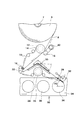
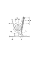
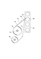
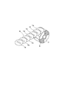
- FIG. 1 It is a block diagram which shows one Example of the label automatic sticking apparatus based on this invention. It is a principal part enlarged view of FIG. It is the principal part enlarged view which further expanded FIG. It is a perspective view which shows the state which adhere
- FIG. 1 is a block diagram showing an embodiment of an automatic label affixing apparatus according to the present invention
- FIG. 2 is an enlarged view of an essential part of FIG. 1
- FIG. 3 is an enlarged view of an essential part It is a perspective view which shows the state which adheres a sheet of labels to a 2nd belt.
- the automatic label attaching apparatus according to the present invention peels a single label one by one from a long label strip obtained by shifting a large number of single labels little by little and overlapping and joining them, and then one sheet It is an apparatus for affixing to an adherend the label which peeled off one by one.
- the label used in the present invention does not use release paper.
- the label strip 8 used in the present invention is a single label (for example, a shape such as a square or a circle) 1a, 1b, 1c, 1d, 1e, 1f, 1g having many identical shapes, as shown in FIG. ... It is something which shifted little by little and piled up and connected.
- the length of the longitudinally overlapping overlapping portion (1x in FIG. 11) of the adjacent labels is desirably 2/3 or more of the longitudinal length of a single label.
- the label strip 8 is wound around a core 7 to form a label roll 6 having a roll shape.
- the single labels 1a, 1b, 1c, 1d, 1e, 1f, 1g... Used in the present invention are subjected to printing on the upper side of the label base, and the printing is protected on the printed surface
- An olefin adhesive as an adhesive means which is coated with an overcoating agent for either UV varnish, oil-based varnish or aqueous varnish, and the tackiness is activated many times above a predetermined temperature on the underside of the label base It is desirable to use a label coated with (heat sensitive label, see FIG. 11).
- This thermal label uses an overcoat agent on one printing surface and an olefin adhesive on the other side to facilitate pseudo-adhesion and peeling of the overcoat agent and the olefin adhesive by heating.
- the heat-sensitive label can be formed into a single heat-sensitive label in any shape such as a circle, an ellipse, a triangle or a square required for the adherend.
- the olefin adhesive can be lightly adhered and peeled off to an object (for example, a belt conveyor) by heating or pressing.
- the protective agent on the upper side of the label for protecting the printing and the adhesive means on the lower side of the label are not limited to the above-mentioned materials.
- the label automatic sticking apparatus has a loop-shaped first belt 10 for temporarily bonding and moving the label strip 8.
- the first belt 10 is looped around the first drive roller 14, the composite shaft (first reverse shaft) 16 and other rollers rotated by the first drive means 12, and the rotation of the first drive roller 14 causes the first belt 10 to rotate. It is moved in the arrow direction (clockwise direction) in FIG.
- the first drive means 12 is, for example, a stepping motor that operates intermittently, and rotates the first drive roller 14 intermittently and also moves the first belt 10 intermittently.
- a nip roller 18 made of rubber or soft synthetic resin or the like and a stepping motor 20 for intermittently driving the nip roller 18 are provided on the outer side of the first belt 10.
- the stepping motor 20 intermittently rotates the nip roller 18 in synchronization with the stepping motor which is the first driving means 12.
- the label strip 8 is pulled out of the label roll 6 so that the adhesive surface side of the label is joined to the outer surface of the first belt 10.
- the first belt 10 and the label strip 8 to be bonded thereto are nipped by the first drive roller 14 disposed inside the first belt 10 and the nip roller 18 disposed outside the first belt 10.
- the nip roller 18 presses the label strip 8 toward the first drive roller 14 (the first belt 10 side) by a pressing force adjusting unit (not shown) with an appropriate force.
- the label strip 8 is crimped to the first belt 10 by an appropriate force by the pressing to the first belt 10 side by the nip roller 18, and the label strip 8 is adhered to the outer surface of the first belt 10 by the crimping force.
- Provisional bonding 1 to 3 are plan views, from which the label strip 8 and the first belt 10 are erected in the vertical direction. 1 There is no separation from the belt 10.
- the label strip 8 temporarily attached to the first belt 10 is intermittently moved along with the first belt 10.
- the amount of one intermittent movement of the first belt 10 by the first drive means 12 is the length of the tip portion 1y (a portion other than the overlapping portion 1x) in the single label.
- heating means (not shown) is provided in the vicinity of an appropriate position of the label strip 8 attached to the first belt 10, and the label strip 8 is You may make it heat.
- the label of the label strip 8 has one surface as an overcoat agent and the other surface as an olefin-based adhesive, the label is heated and the adhesive strength of the overlapping portions of the labels is increased by heating the labels. It is activated and exfoliated.
- the compound shaft (first reverse shaft) 16 integrally forms the large diameter portion 16 a on the left and right and the small diameter portion 16 b in the center of the large diameter portion 16 a on the left and right,
- the compound shaft 16 is a fixed shaft which does not rotate.
- the first belt 10 is wound around the small diameter portion 16 b of the composite shaft 16, and the first belt 10 is inverted at an angle close to 180 degrees around the position of the small diameter portion 16 b of the composite shaft 16. It is set to.
- the leading end 1y of the label 1a at the top of the label strip 8 is peeled off from the first belt 10 at the position of the composite shaft 16, and Project in the same direction as the direction of travel.
- the automatic label affixing apparatus has, in addition to the first belt 10, a loop-shaped second belt 22 for temporarily bonding and moving the labels peeled off from the label strip 8 one by one.
- the second belt 22 is wound around the second driving roller 26, the second reverse shaft 28 and other rollers rotated by the second driving means 24, and the rotation of the second driving roller 26 causes the direction of the arrow (see It is moved to During operation of the apparatus, the drive roller 26 rotates at a constant speed, and the second belt 22 moves continuously in a loop at a constant speed.
- the second belt 22 is set to move in contact with a part of the outer periphery of the large diameter portion 16 a of the composite shaft 16.
- the leading end 1y of the leading label 1a of the label strip 8 is in a state of being peeled off from the first belt 10
- the leading end position of the leading end portion 1y of the label 1a is set so as to be in contact with the second belt 22 a little more.
- the leading label 1 a is moved in the same direction as the moving direction before the first belt 10 is reversed by the compound shaft 16. That is, as shown in FIG. 3A, the surface on the adhesive (adhesion means) 5 side of the leading end position of the tip portion 1y of the label 1a is adhered (temporarily adhered) to the second belt 22.
- the angle between the tip portion 1y of the label 1a and the second belt 22 in contact is ⁇ 1
- the tip portion 1y of the label 1a moves to the second belt 22
- the entire surface of the label 1 a on the side of the adhesive 5 adheres to the second belt 22.
- the first belt 10 stops moving.
- the state at the time of the stop is the state shown in FIG. 2 (the state before the leading edge of the next label 1 b contacts the second belt 22).
- the next label 1 b adheres to the second belt 22 as shown in FIG. 2 and FIG. 3.
- the labels 1 are temporarily adhered to the second belt 22 one by one at a time with a slight interval.
- the label 1a adhered to the second belt 22 is then conveyed to a second reversing shaft 28 (FIG. 1) for reversing the second belt 22 by approximately 180 degrees.
- the label 1 temporarily bonded to the second belt 22 is for preventing falling off from the second belt 22 or to reinforce the temporary bonding on the way to move the second belt 22 to the second reverse shaft 28.
- the second belt 22 is pressed by the pressing means 30 of the second embodiment.
- the pressing means 30 is preferably provided, but may not be provided.
- a heating means for heating the label 1 temporarily bonded to the second belt 22 may be provided in the vicinity of the second reversing shaft 28 inside or outside the loop-shaped second belt 22.
- the label 1 which has reached the position of the second reversing shaft 28 is peeled off from the second belt 22 by reversing the second belt 22 at the second reversing shaft 28, and the second belt just before reaching the second reversing shaft 28 position It is peeled off from the second belt 22 in the same direction as the moving direction of 22 and is projected to the outside.
- a pressing roller (pressing means) 32 for pressing the label 1 against an adherend 36 is provided in the vicinity of the protruding position of the label 1 to be peeled off from the second belt 22.
- the label 1 separated from the belt 22 is brought into contact with the adherend 36.
- a goods transfer belt conveyor 34 is provided below the arrangement position of the second reversing shaft 28.
- An adherend 36 which is a product for attaching a label, is placed on the commodity transfer belt conveyor 34, and the adherend 36 is placed on the commodity transfer belt conveyor 34 and transported in a predetermined direction.
- the moving speed of the product transfer belt conveyor 34 and the moving speed of the second belt 22 are basically set to the same speed. Further, the traveling direction of the commodity transfer belt conveyor 34 and the traveling direction of the second belt 22 immediately before reaching the position of the second reverse shaft 28 are the same traveling direction (not opposite direction).
- the angle ⁇ 2 between the direction of travel of the product transfer belt conveyor 34 and the direction of travel of the second belt 22 can be a small acute angle (eg, ⁇ 2 of 15 ° to 45 °).
- Sensors 38 are provided on both sides or one side in the vicinity of the product transfer belt conveyor 34.
- the sensor 38 When the sensor 38 detects the arrival of the adherend 36 at a predetermined position, the sensor 38 operates the first drive means 12 to move the first belt 10, and the label 1a at the head position of the label strip 8 is moved to the second position.
- the belt 22 is brought into contact.
- the timing at which the label 1 a contacts the second belt 22 matches the timing at which the label 1 peeled off from the second belt 22 adheres to the adherend 36.
- the timing for starting driving the first driving means 12 and the timing for stopping driving may be performed by means other than the sensor 38.
- the first drive means 12 is set to stop the operation when a predetermined time has elapsed after the operation.
- another sensor other than the sensor 38 may be provided in the vicinity of the commodity transfer belt conveyor 34 so as to stop the operation of the driving means 12 when another sensor detects the adherend 36.
- the label strip 8 pulled out from the label roll 6 shown in FIG. 1 is held between the first drive roller 14 and the nip roller 18 in the middle thereof, and the adhesion direction side is temporarily adhered to the first belt 10 from the holding position. It is done.
- FIG. 2 in the state where the movement of the first belt 10 and the label strip 8 is stopped (standby state), the leading end of the tip portion 1 y of the leading label 1 a of the label strip 8 is the second The position is set so as to be slightly in front of the belt 22. Even in the standby state in which the movement of the first belt 10 and the label strip 8 is stopped, the goods transfer belt conveyor 34 which moves with the second belt 22 and the adherend 36 moved continuously. Do.
- the first drive means 12 In the standby state, when the sensor 38 detects the adherend 36 which is placed on the commodity transfer belt conveyor 34 and moves at a predetermined position, the first drive means 12 operates to operate the first belt 10 and the label strip 8. Move By driving the first drive means 12, the leading end portion 1 y of the leading label 1 a of the label strip 8 is adhered to the second belt 22. When the leading end portion 1y of the next label 1b arrives slightly before the second belt 22, the operation of the first driving means 12 is stopped. In the state where the operation of the first drive means 12 is stopped, the label strip 8 is in the same standby state as in FIG. That is, when the first driving means 12 is driven once, the next label 1b is located at the position where the label 1a shown in FIG. 2 was present, and the next label 1c is located at the position where the label 1b was present. .
- the second belt 22 is moved, and therefore, the entire length of the label 1a is peeled off from the label strip 8 by being pulled by the second belt 22 and the second belt 22 Bond to While the label 1a is sequentially adhered to the second belt 22 in its entire length, the label 1 (located near the second reverse shaft 28) peeled off from the second belt 22 is attached to the adherend 36 Make sure that the entire length adheres sequentially.
- the first drive means 12 operates to move the first belt 10 and the label strip 8.
- the label at the leading end (the leading end in FIG. 2) of the label strip 8 is adhered to the second belt 22, pulled by the second belt 22, and adhered to the second belt 22.
- the label 1 already adhered to the second belt 22 and located near the second reverse shaft 28 is peeled off from the second belt 22 and adhered to the adherend 36.
- the same operation is repeated.
- the first belt 10 and the label strip 8 are intermittently moved to bond the labels 1 from the label strip 8 one by one to the second belt 22 at intervals.
- the label 1 adhered to the second belt 22 with a gap therebetween is peeled off from the second belt 22 at the position of the second reversing shaft 28.
- the label 1 peeled off from the second belt 22 is moved along the traveling direction on the upstream side of the second reversing shaft 28, and is placed on the commodity transfer belt conveyor 34 and moved. It adheres to 36 in order.
- the advancing direction of the label 1 peeled off from the second belt 22 is the same as the advancing direction of the adherend 36 (not the reverse direction), and the label 1 and the adherend 36 Is moved at the same speed.
- the angle ⁇ 2 between the direction of travel of the label 1 and the adherend 36 can be set to a small acute angle (eg, 15 ° to 45 °).
- a small acute angle eg, 15 ° to 45 °.
- the label 1a on the tip side of the moving label strip 8 collides with the moving second belt 22 and the adhesive 5 side of the tip of the label 1a adheres to the second belt 22. Since the second belt 22 is always moving, the label 1a adhered to the second belt 22 moves while being pulled by the second belt 22, and the adhesive 5 side of the label 1a is brought into contact with the second belt 22. When the angle at which the label 1 a on the tip side of the label strip 8 collides with the second belt 22 is close to a right angle, the adhesive 5 near the tip of the label 1 a may not contact the second belt 22 .
- the air jetting means 40 is provided near the compound shaft 16.
- the air ejected from the air ejection means 40 is for ejecting the air to the position of the adhesive 5 at the tip portion 1y of the leading label 1a in the standby state.
- the leading end 1y of the leading label 1a is not adhered to the next label 1b or the like.
- the air jetting means 40 is provided at a position facing the surface provided with the adhesive 5 (adhesion means) of the front end portion 1y of the leading label 1a of the label strip 8.
- the air jetting means 40 is operated to jet air toward the adhesive 5 side of the tip portion 1y of the label 1a.
- the surface of the leading end 1y of the leading label 1a on the adhesive 5 side is curved in an arc toward the outside (opposite to the adhesive 5) by the jetted air.
- the adhesive 5 side of the leading end 1y of the leading label 1a is made to face the second belt 22 by curving the surface of the leading end 1y of the leading label 1a on the adhesive 5 side toward the opposite side of the adhesive 5.
- FIG. 7 and FIG. 8 temporarily bond the label 1 (label 1a) to the second belt 22 and show a structure and method different from those of FIG.
- the adhesive 5 side of the front end portion 1y of the leading label 1a to be peeled off from the label strip 8 is bent back by the air injection means 40 so as to face the second belt 22, the adhesion of the label 1a The agent 5 side is adhered to the second belt 22.
- the adhesive 5 side of the leading end portion 1y of the label 1a is located at an intermediate position of the second belt 22 (intermediate position between the left and right end rollers) stretched between the left and right end rollers. Contact For this reason, the interval between the rollers at the left and right ends of the second belt 22 is long, and the length of the second belt 22 is long.
- FIGS. 7 and 8 show another structure and method for temporarily bonding the adhesive 5 side of the leading end portion 1y of the leading label 1a to the second belt 22, and the air jet means 40 shown in FIG. Instead, a three-dimensional label moving member 90 is used.
- the label moving member 90 changes the moving direction (direction E in FIG. 7) of the leading end portion 1y of the leading label 1a peeled off from the label strip 8 and reverses the label 1a, and the label 1a is moved to a predetermined position of the second belt 22. It is for moving toward (described later).
- the label moving member 90 has a protrusion 92 for pressing the adhesive 5 side of the tip portion 1y of the label 1a to invert the tip portion 1y of the label 1a.
- the label moving member 90 moves its center-of-gravity position in the order of the position A, the position B, the position C, and the position D.
- One moving end of the label moving member 90 is set to a position A
- the other moving end is set to a position D
- the middle position of movement is set to a position B or a position C.
- the label moving member 90 reaches the position D, it returns to the position A via the position C and the position B.
- the position A of the label moving member 90 is in a standby state in which the movement between the first belt 10 and the label strip 8 is stopped.
- the tip of the tip portion 1y of the label 1a is a label moving member 90 It is arranged in a close position but not in contact with the label moving member 90. Thereafter, the standby state is released, and the leading end 1y of the label 1a advances in the direction E in FIG. 7, and a part of the leading end 1y of the label 1a passes near the protrusion 92 of the label moving member 90.
- the label moving member 90 moves in a direction substantially perpendicular to the moving direction (direction E) of the tip portion 1y of the label 1a, and the protrusion 92 of the label moving member 90 presses the adhesive 5 side of the tip portion 1y of the bell 1a. .
- the protruding portion 92 of the label moving member 90 pushes the adhesive 5 side of the tip portion 1y of the bell 1a, so that the adhesive 5 side of the tip portion 1y of the label 1a is exposed to the outside of the arc shape Are inverted (the state of position B of the label moving member 90). Thereafter, the label moving member 90 moves the label 1a along the direction in which the tip end 1y of the label 1a is inverted. The label moving member 90 moves the label 1a which has been kept inverted. That is, the label moving member 90 continues to move in the direction moved in a direction substantially perpendicular to the moving direction (direction E) of the tip portion 1y of the label 1a at the position A, from the position B to the position C in FIG. Move.
- the label moving member 90 While the label moving member 90 is moved from the position B to the position C, the advancing direction of the tip portion 1 of the label 1 a is completely reversed, and the label 1 is attached to one surface (joining surface) 94 of the label moving member 90. Contact with the adhesive 5 side of the Thereafter, while the label moving member 90 is moved from the position C to the position D, the bonding surface 94 of the label moving member 90 and the adhesive 5 side of the label 1a are in contact with each other. 90 and label 1a move in a linear direction.
- the adhesive 5 side of the leading end of the label 1a contacts the second belt 22 and presses the roller 96 on which the second belt 22 is wound It is nipped between the roller 98.
- the label 1 is pressed and held (moved) by the roller 96 and the pressing roller 98, the label 1 is in a state of being temporarily adhered to the second belt 22, and the label 1 is moved together with the second belt 22.
- the label moving member 90 When the label 1 is temporarily adhered to the second belt 22 and moved together with the second belt 22, the label moving member 90 returns from the position D to the position A via the positions C and B. After that, when the next label 1 moves again and its leading end passes near the protrusion 92 of the label moving member 90, the label moving member 90 moves to press the label 1 and reverse the moving direction of the label 1 , And moved together with the label moving member 90. The label 1 is finally sandwiched between the roller 96 and the pressure roller 98, temporarily adhered to the second belt 22, and moved together with the second belt 22. Such an operation is sequentially repeated to temporarily bond the labels 1 one by one to the second belt 22. When the label moving member 90 is used, the label 1 can be temporarily adhered to the second belt 22 at the roller 98 position which is the reverse position of the second belt 22. Therefore, when the label moving member 90 is used, the length of the second belt 22 can be shortened.
Landscapes
- Labeling Devices (AREA)
Abstract
L'invention porte sur un dispositif et un procédé d'application automatique d'étiquette à l'aide d'un long ruban d'étiquettes dans lequel une certaine quantité d'étiquettes unitaires sont reliées d'une manière continue en se chevauchant partiellement les unes les autres, et aptes à appliquer précisément et automatiquement un grand nombre d'étiquettes par unité de temps même si un objet sur lequel l'étiquette doit être collée est fait d'un matériau qui est glissant par rapport à un moyen adhésif. Un ruban d'étiquettes (8) est temporairement fixé sur une première courroie (10) qui se déplace par intermittence. Au niveau de la position d'un premier arbre de renversement (16) qui renverse la première courroie (10), les étiquettes temporairement fixées (1) sont retirées une par une du ruban d'étiquettes (8). Les étiquettes (1) retirées du ruban d'étiquettes (8) sont séquentiellement mises en contact avec une seconde courroie (22) qui se déplace par rotation, et les étiquettes (1) sont temporairement fixées à la seconde courroie (22) à un certain intervalle. Au niveau de la position d'un second arbre de renversement (28) qui renverse la seconde courroie (22), les étiquettes temporairement fixées à la seconde courroie (22) sont retirées de la seconde courroie. La direction de déplacement des étiquettes (1) retirées de la seconde courroie (22) et la direction de déplacement des objets sur lesquels les étiquettes doivent être collées sont réglées à la même direction, et les étiquettes (1) sont destinées à être collées sur les objets (36).
Applications Claiming Priority (4)
| Application Number | Priority Date | Filing Date | Title |
|---|---|---|---|
| JP2010-287215 | 2010-12-24 | ||
| JP2010287215 | 2010-12-24 | ||
| JP2011091142 | 2011-04-15 | ||
| JP2011-091142 | 2011-04-15 |
Publications (1)
| Publication Number | Publication Date |
|---|---|
| WO2012086254A1 true WO2012086254A1 (fr) | 2012-06-28 |
Family
ID=46313541
Family Applications (1)
| Application Number | Title | Priority Date | Filing Date |
|---|---|---|---|
| PCT/JP2011/067247 Ceased WO2012086254A1 (fr) | 2010-12-24 | 2011-07-28 | Dispositif d'application automatique d'étiquette et procédé d'application automatique d'étiquette |
Country Status (2)
| Country | Link |
|---|---|
| TW (1) | TW201302499A (fr) |
| WO (1) | WO2012086254A1 (fr) |
Cited By (10)
| Publication number | Priority date | Publication date | Assignee | Title |
|---|---|---|---|---|
| JP5378621B1 (ja) * | 2013-04-11 | 2013-12-25 | 西川コミュニケーションズ株式会社 | ラベル貼付装置及びラベル貼付方法 |
| WO2013191233A1 (fr) * | 2012-06-22 | 2013-12-27 | 株式会社ウイル・コーポレーション | Dispositif de pose d'étiquettes |
| WO2014196334A1 (fr) * | 2013-06-04 | 2014-12-11 | 株式会社ウイル・コーポレーション | Dispositif d'application d'étiquettes |
| JP2015067319A (ja) * | 2013-09-30 | 2015-04-13 | 西川コミュニケーションズ株式会社 | ラベル貼付装置 |
| WO2015083693A1 (fr) * | 2013-12-05 | 2015-06-11 | ミクロ株式会社 | Dispositif d'alimentation en étiquettes |
| JP2016030628A (ja) * | 2014-07-29 | 2016-03-07 | フレンド株式会社 | ラベル貼付装置 |
| JP2016037311A (ja) * | 2014-08-08 | 2016-03-22 | フレンド株式会社 | ラベル貼付装置 |
| WO2016121017A1 (fr) * | 2015-01-28 | 2016-08-04 | 西川コミュニケーションズ株式会社 | Appareil de fixation d'étiquettes |
| US20180346174A1 (en) * | 2017-04-20 | 2018-12-06 | Actega North America Technologies, Inc. | Label application systems |
| US11511550B2 (en) | 2018-07-02 | 2022-11-29 | Actega North America Technologies, Inc. | Systems and methods for decorating substrates |
Families Citing this family (1)
| Publication number | Priority date | Publication date | Assignee | Title |
|---|---|---|---|---|
| JP6324213B2 (ja) * | 2014-05-27 | 2018-05-16 | サトーホールディングス株式会社 | 弾性体ローラー |
Citations (9)
| Publication number | Priority date | Publication date | Assignee | Title |
|---|---|---|---|---|
| US4468274A (en) * | 1981-07-31 | 1984-08-28 | E.D.M. Corporation | Method and apparatus for bonding thermosensitive adhesive label |
| US5895552A (en) * | 1994-09-14 | 1999-04-20 | Osaka Sealing Printing Co., Ltd. | Bonding apparatus for cutting label continuum having labels formed successively and bonding label to object |
| WO2000007883A2 (fr) * | 1998-08-05 | 2000-02-17 | Advanced Label Systems, Inc. | Dispositif et procede servant a appliquer des etiquettes sans doublure |
| US6280549B1 (en) * | 1993-12-27 | 2001-08-28 | Moore Business Forms, Inc. | Die-cut linerless label production |
| JP3205804B2 (ja) * | 1998-03-04 | 2001-09-04 | 株式会社佐々木印刷 | ノーセパレータラベル |
| JP2009214926A (ja) * | 2008-03-12 | 2009-09-24 | Sato Knowledge & Intellectual Property Institute | ラベル貼付装置 |
| WO2010082533A1 (fr) * | 2009-01-13 | 2010-07-22 | ランベル合同会社 | Etiquette thermosensible et corps de rouleau utilisant l'étiquette thermosensible |
| WO2010101101A1 (fr) * | 2009-03-04 | 2010-09-10 | ランベル合同会社 | Dispositif d'application automatique d'étiquettes et procédé d'application automatique d'étiquettes |
| JP3163087U (ja) * | 2010-07-09 | 2010-09-30 | 英二郎 滑川 | 台紙無しラベル剥離・排出手段 |
-
2011
- 2011-07-28 WO PCT/JP2011/067247 patent/WO2012086254A1/fr not_active Ceased
- 2011-12-23 TW TW100148386A patent/TW201302499A/zh unknown
Patent Citations (9)
| Publication number | Priority date | Publication date | Assignee | Title |
|---|---|---|---|---|
| US4468274A (en) * | 1981-07-31 | 1984-08-28 | E.D.M. Corporation | Method and apparatus for bonding thermosensitive adhesive label |
| US6280549B1 (en) * | 1993-12-27 | 2001-08-28 | Moore Business Forms, Inc. | Die-cut linerless label production |
| US5895552A (en) * | 1994-09-14 | 1999-04-20 | Osaka Sealing Printing Co., Ltd. | Bonding apparatus for cutting label continuum having labels formed successively and bonding label to object |
| JP3205804B2 (ja) * | 1998-03-04 | 2001-09-04 | 株式会社佐々木印刷 | ノーセパレータラベル |
| WO2000007883A2 (fr) * | 1998-08-05 | 2000-02-17 | Advanced Label Systems, Inc. | Dispositif et procede servant a appliquer des etiquettes sans doublure |
| JP2009214926A (ja) * | 2008-03-12 | 2009-09-24 | Sato Knowledge & Intellectual Property Institute | ラベル貼付装置 |
| WO2010082533A1 (fr) * | 2009-01-13 | 2010-07-22 | ランベル合同会社 | Etiquette thermosensible et corps de rouleau utilisant l'étiquette thermosensible |
| WO2010101101A1 (fr) * | 2009-03-04 | 2010-09-10 | ランベル合同会社 | Dispositif d'application automatique d'étiquettes et procédé d'application automatique d'étiquettes |
| JP3163087U (ja) * | 2010-07-09 | 2010-09-30 | 英二郎 滑川 | 台紙無しラベル剥離・排出手段 |
Cited By (13)
| Publication number | Priority date | Publication date | Assignee | Title |
|---|---|---|---|---|
| WO2013191233A1 (fr) * | 2012-06-22 | 2013-12-27 | 株式会社ウイル・コーポレーション | Dispositif de pose d'étiquettes |
| JP5378621B1 (ja) * | 2013-04-11 | 2013-12-25 | 西川コミュニケーションズ株式会社 | ラベル貼付装置及びラベル貼付方法 |
| WO2014196334A1 (fr) * | 2013-06-04 | 2014-12-11 | 株式会社ウイル・コーポレーション | Dispositif d'application d'étiquettes |
| JP2015067319A (ja) * | 2013-09-30 | 2015-04-13 | 西川コミュニケーションズ株式会社 | ラベル貼付装置 |
| WO2015083693A1 (fr) * | 2013-12-05 | 2015-06-11 | ミクロ株式会社 | Dispositif d'alimentation en étiquettes |
| JP2016030628A (ja) * | 2014-07-29 | 2016-03-07 | フレンド株式会社 | ラベル貼付装置 |
| JP2016037311A (ja) * | 2014-08-08 | 2016-03-22 | フレンド株式会社 | ラベル貼付装置 |
| WO2016121017A1 (fr) * | 2015-01-28 | 2016-08-04 | 西川コミュニケーションズ株式会社 | Appareil de fixation d'étiquettes |
| US20180346174A1 (en) * | 2017-04-20 | 2018-12-06 | Actega North America Technologies, Inc. | Label application systems |
| US10889401B2 (en) * | 2017-04-20 | 2021-01-12 | Actega North America Technologies, Inc. | Label application systems |
| US11325737B2 (en) | 2017-04-20 | 2022-05-10 | Actega North America Technologies, Inc. | Label application systems |
| US11511550B2 (en) | 2018-07-02 | 2022-11-29 | Actega North America Technologies, Inc. | Systems and methods for decorating substrates |
| US12090769B2 (en) | 2018-07-02 | 2024-09-17 | Actega North America Technologies, Inc. | Systems and methods for decorating substrates |
Also Published As
| Publication number | Publication date |
|---|---|
| TW201302499A (zh) | 2013-01-16 |
Similar Documents
| Publication | Publication Date | Title |
|---|---|---|
| WO2012086254A1 (fr) | Dispositif d'application automatique d'étiquette et procédé d'application automatique d'étiquette | |
| WO2010101101A1 (fr) | Dispositif d'application automatique d'étiquettes et procédé d'application automatique d'étiquettes | |
| TW200401236A (en) | Label, a method for its use, and a method and apparatus for affixing the label | |
| KR20090034271A (ko) | 시트 첩부 장치 | |
| WO2012017750A1 (fr) | Dispositif de collage de feuille et procédé de collage | |
| JP5996295B2 (ja) | ラベル貼付装置 | |
| JP5922220B2 (ja) | ラベルの製造方法 | |
| JP4733541B2 (ja) | ラベル貼付装置 | |
| JP2010023862A (ja) | ラベル貼付装置およびラベル貼付方法 | |
| JP3966773B2 (ja) | 筒状フィルム接続方法及びフィルムロール | |
| JP2014141267A (ja) | ラベル貼付装置及びラベル貼付方法 | |
| US7575649B2 (en) | Label structure and label structure obtaining method | |
| JP5378621B1 (ja) | ラベル貼付装置及びラベル貼付方法 | |
| JP5897799B2 (ja) | ラベル貼付装置 | |
| JP2007230566A (ja) | ラベル貼付装置およびラベル貼付方法 | |
| JP5775735B2 (ja) | シート貼付装置および貼付方法 | |
| JP4152030B2 (ja) | フィルム貼付装置 | |
| JP4183214B2 (ja) | ラベルの除去装置 | |
| JP5771661B2 (ja) | ラベル貼付装置 | |
| JP4152031B2 (ja) | フィルム貼付装置 | |
| JP4307640B2 (ja) | ラベル貼付機 | |
| JP4526878B2 (ja) | 非接触データキャリア部材取付方法及び装置 | |
| JP4822520B2 (ja) | ラベル貼付装置 | |
| JP2010105695A (ja) | ラベル移送装置及びラベル貼付装置 | |
| JP2010285188A (ja) | ラベル移送貼着装置 |
Legal Events
| Date | Code | Title | Description |
|---|---|---|---|
| 121 | Ep: the epo has been informed by wipo that ep was designated in this application |
Ref document number: 11851161 Country of ref document: EP Kind code of ref document: A1 |
|
| NENP | Non-entry into the national phase |
Ref country code: DE |
|
| 32PN | Ep: public notification in the ep bulletin as address of the adressee cannot be established |
Free format text: NOTING OF LOSS OF RIGHTS PURSUANT TO RULE 112(1) EPC |
|
| NENP | Non-entry into the national phase |
Ref country code: JP |
|
| 122 | Ep: pct application non-entry in european phase |
Ref document number: 11851161 Country of ref document: EP Kind code of ref document: A1 |