WO2013191233A1 - Dispositif de pose d'étiquettes - Google Patents
Dispositif de pose d'étiquettes Download PDFInfo
- Publication number
- WO2013191233A1 WO2013191233A1 PCT/JP2013/066915 JP2013066915W WO2013191233A1 WO 2013191233 A1 WO2013191233 A1 WO 2013191233A1 JP 2013066915 W JP2013066915 W JP 2013066915W WO 2013191233 A1 WO2013191233 A1 WO 2013191233A1
- Authority
- WO
- WIPO (PCT)
- Prior art keywords
- belt
- label
- moving
- shaft
- moving body
- Prior art date
- Legal status (The legal status is an assumption and is not a legal conclusion. Google has not performed a legal analysis and makes no representation as to the accuracy of the status listed.)
- Ceased
Links
Images






Classifications
-
- B—PERFORMING OPERATIONS; TRANSPORTING
- B65—CONVEYING; PACKING; STORING; HANDLING THIN OR FILAMENTARY MATERIAL
- B65C—LABELLING OR TAGGING MACHINES, APPARATUS, OR PROCESSES
- B65C9/00—Details of labelling machines or apparatus
- B65C9/08—Label feeding
- B65C9/18—Label feeding from strips, e.g. from rolls
-
- B—PERFORMING OPERATIONS; TRANSPORTING
- B65—CONVEYING; PACKING; STORING; HANDLING THIN OR FILAMENTARY MATERIAL
- B65C—LABELLING OR TAGGING MACHINES, APPARATUS, OR PROCESSES
- B65C9/00—Details of labelling machines or apparatus
- B65C9/08—Label feeding
- B65C9/18—Label feeding from strips, e.g. from rolls
- B65C9/1865—Label feeding from strips, e.g. from rolls the labels adhering on a backing strip
-
- B—PERFORMING OPERATIONS; TRANSPORTING
- B65—CONVEYING; PACKING; STORING; HANDLING THIN OR FILAMENTARY MATERIAL
- B65C—LABELLING OR TAGGING MACHINES, APPARATUS, OR PROCESSES
- B65C9/00—Details of labelling machines or apparatus
- B65C9/0006—Removing backing sheets
- B65C2009/0009—Removing backing sheets by means of a peeling tip
-
- B—PERFORMING OPERATIONS; TRANSPORTING
- B65—CONVEYING; PACKING; STORING; HANDLING THIN OR FILAMENTARY MATERIAL
- B65C—LABELLING OR TAGGING MACHINES, APPARATUS, OR PROCESSES
- B65C9/00—Details of labelling machines or apparatus
- B65C9/08—Label feeding
- B65C9/18—Label feeding from strips, e.g. from rolls
- B65C9/1865—Label feeding from strips, e.g. from rolls the labels adhering on a backing strip
- B65C2009/1888—Overlapping labels
Definitions
- the present invention relates to a label affixing device for affixing a label to an adherend, for example, by peeling a label from a label strip formed by connecting a plurality of labels (no separator labels) that do not use release paper into a strip.
- the present invention relates to a label affixing device to be affixed to a label.
- Patent Document 1 proposes a label roll 6 (see FIG. 9 (a)) in which a no-separator label 1 is shifted and overlapped and connected to form a band shape and wound around a tubular core 7 in a roll shape. Has been.
- the label roll 6 is formed by winding a label strip 8 formed by connecting a plurality of no-separator labels (hereinafter simply referred to as “labels”) 1 into a roll. ing.
- the label 1 is provided with an overcoat layer 3 on the surface of the label substrate 2 and an adhesive layer (adhesive layer) 4 on the back surface (see FIG. 9B).
- the label strip 8 has one end of the overcoat layer 3 of the second label 1b attached to one end of the adhesive layer 4 of the first label 1a, and the other of the adhesive layer 4 of the second label 1b.
- One end of the overcoat layer 3 of the third label 1c is sequentially attached to the end, and a plurality of labels 1 are continuously connected.
- Patent Document 2 discloses a label in which the label strip 8 is pulled out from the label roll 6 configured as described above, the label 1 is peeled off from the label strip 8 one by one, and the label 1 is attached to the adherend W. Automatic sticking devices have been proposed. Hereinafter, the label automatic sticking apparatus described in Patent Document 2 will be described with reference to FIG.
- the label automatic affixing apparatus transports a label transfer belt conveyor 100 for temporarily adhering and transferring a label strip 8 drawn from a label roll 6 (not shown), and an adherend W for attaching a label.
- the product conveyor belt conveyor 200 and air jet means 300 for jetting air to the head of the label strip 8 are provided.
- a reversing shaft 102 for reversing the belt conveyor 100 is provided at an end portion in the traveling direction of the label transfer belt conveyor 100, and the reversing shaft 102 reverses the traveling direction of the belt conveyor 100 by approximately 180 degrees. It has become.
- a label pressing mechanism 400 for peeling the labels 1 from the label strip 8 one by one is provided in the vicinity of the reversing shaft 102.
- This label automatic sticking device operates as follows, and sticks the label 1 to the adherend W.
- the label belt 8 is temporarily bonded to the label transfer belt conveyor 100, and the label transfer belt conveyor 100 is driven. Thereby, the label strip 8 moves together with the label transfer belt conveyor 100.
- the head of the label strip 8 moves to the position of the reversing shaft 102, the leading end 1y of the label 1a at the leading end is peeled off from the label transfer belt conveyor 100, and the peeled leading end 1y is transferred to the label. It protrudes forward from the belt conveyor 100 (FIG. 10A).
- the automatic label sticking device detects that the leading end 1y has protruded to a predetermined position with a sensor (not shown) and stops driving the label transfer belt conveyor 100 (standby state). It is configured.
- the automatic label affixing device detects that the adherend W moving on the product transfer belt conveyor 200 has passed a predetermined position (closer to the vicinity of the reversing shaft 102) (not shown). ), The air ejecting means 300 is driven, and air is ejected to the protruding end portion 1y of the label 1a. Thereby, the adhesion surface of the tip 1y is warped in an arc. The adherend W moving on the product transfer belt conveyor 200 comes into contact with the protruding tip 1y of the label 1 so that the tip 1y of the label 1a adheres to the adherend W. To do.
- the adherend W moves in a state where the leading end portion 1a of the label 1 is adhered, and the label 1a is peeled off from the label 1b temporarily adhered to the label transfer belt conveyor 100, and the adherend W (See FIGS. 10B and 10C). Further, when the label 1a is peeled off from the label strip 8, the label pressing mechanism 400 presses the label strip 8 toward the label transfer belt conveyor 100, so that the label connected to the label 1a together with the label 1a. (For example, label 1b) is prevented from peeling off.
- the label automatic sticking device of Patent Document 2 described above has the following problems. Specifically, the label automatic pasting apparatus described above is configured to temporarily attach and move a label strip in which a plurality of labels are overlapped and connected to a label conveyor belt conveyor, and label the label strip from the beginning of the moved label strip. Are peeled off one by one and attached to the adherend. And since said label automatic sticking apparatus peels a label one by one, when sticking a label to a to-be-adhered body, the belt conveyor for label transfer is stopped. That is, the label automatic sticking apparatus described above peels off the label from the label strip and sticks it to the adherend only by the force pulled from the adherend moving on the product belt conveyor.
- the label automatic sticking device described above cannot be peeled off as desired by the label adhesive variation or the adherend material, and the label cannot be stuck at a predetermined position on the adherend.
- the material of the adherend is slippery, a phenomenon has occurred in which a label cannot be attached to a predetermined position of the adherend.
- the automatic label pasting apparatus described above requires a label pressing mechanism that operates accurately in order to peel the labels one by one from the label strip, and has a problem that the apparatus becomes complicated.
- the present invention has been made in view of the above problems, and is a label that peels off a label from a label strip formed in a strip shape by connecting a plurality of labels not using release paper, and attaches the label to an adherend with high accuracy.
- An object is to provide a sticking device.
- the present invention for solving the above technical problem is a label affixing device for peeling off a label from a label strip formed by shifting and joining a large number of labels having an adhesive layer formed on the back surface and attaching the label to an adherend.
- a belt conveyor for moving the adherend, a first belt mechanism having a loop-like first belt for temporarily adhering and moving the label strip, and a label peeled off from the label strip one by one.
- a second belt mechanism having a loop-shaped second belt to be bonded and moved, and a label peeled off one by one from a label belt temporarily bonded to the first belt, transferred to the second belt, and transferred to the second belt.
- a label moving mechanism for temporarily adhering the label wherein the second belt mechanism is wound around the second belt driving means for continuously moving the second belt and the second belt.
- the label is affixed to the adherend by adhering it to the adherend that moves on the belt conveyer while protruding and extruding the leading portion of the label that has been pushed out from the second belt. It is characterized by.
- the first belt mechanism includes a first belt driving unit that intermittently moves the first belt, and a first belt reversing shaft that is wound around the first belt and reverses the first belt.
- the first belt is intermittently moved by the first belt driving means, and the leading end portion of the leading label of the label strip temporarily bonded to the first belt at the position of the first belt reversing shaft is
- the second belt mechanism has a guide shaft that is disposed opposite to the second belt reversing shaft and that reverses the second belt by being wound around the second belt.
- the label moving mechanism includes a moving body that reciprocates between the vicinity of the first belt reversing shaft of the first belt mechanism and the vicinity of the guide shaft of the second belt mechanism, and the moving body includes the first belt. Label tip protruding from The label is peeled off from the label strip and transferred to the second belt wound around the guide shaft by moving it toward the guide shaft by hooking and temporarily adhering to the second belt. It is desirable to temporarily bond the label to the surface.
- the label sticking device of the present invention includes the second belt for temporarily bonding and moving the labels peeled from the label strip one by one.
- the present invention also includes a label moving mechanism that peels off the labels one by one from the label belt temporarily bonded to the first belt, transfers the labels to the second belt, and temporarily bonds the labels to the second belt one by one. Yes. That is, in the present invention, since the labels are separated one by one in the stage before the label is applied to the adherend, the belt (secondly attached) when the label is applied to the adherend is attached. Belt) can be moved.
- the label when a label is attached to the adherend that is moving on the belt conveyor, the label can be pushed out to the adherend by the movement of the second belt, and the label is surely removed from the second belt. Can be peeled off.
- the label sticking device that attaches a label to an adherend with high accuracy.
- the moving body has a claw portion for hooking and pressing the label at one end thereof, and a plate-shaped vibration preventing member at the other end.
- the label moving mechanism includes a guide rail extending from the vicinity of the first belt reversing shaft of the first belt mechanism to the vicinity of the guide shaft of the second belt mechanism, and the moving body moves along the guide rail.
- the claw portion has a front surface formed in a taper shape, and is disposed so that one side surface thereof faces the label adhesion surface of the first belt, and the moving body is arranged along the guide rail.
- the back surface of the protruding label tip is hooked and pressed on the front surface of the claw portion, and the back surface of the claw portion is temporarily bonded to one side surface of the claw portion while reversing the label. It is desirable to up to two belt adapted to transfer the label. Further, a cam mechanism is provided on the first belt reversing shaft side of the guide rail so that the claw portion of the movable body is moved in a direction away from the label adhesion surface of the first belt from a position in contact with the label front end portion. It is desirable to be provided. By comprising in this way, a label can be reliably moved from a 1st belt to a moving body. Further, the cam mechanism can avoid interference with the label 1 remaining on the first belt.
- the traveling direction of the belt conveyor and the traveling direction of the second belt moving toward the second belt reversal axis are substantially the same direction.
- the second belt mechanism includes a pressing roller that is disposed opposite to the guide shaft and sandwiches the second belt together with the guide shaft, and a label transported by the moving body is connected to the guide shaft. It is desirable that the second belt is temporarily bonded by being sandwiched between the pressing rollers. By comprising in this way, the adhesion failure of the label to a 2nd belt can be prevented.
- the present invention it is possible to provide a label sticking device that peels off a label from a label strip formed in a strip shape by connecting a plurality of labels that do not use release paper, and attaches the label to an adherend with high accuracy.
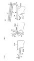
- FIG. 6B is a schematic diagram illustrating a state where the claw portion of the moving body is hooked on the label leading end portion protruding from the first belt.
- FIG. 6B is a schematic diagram illustrating a state where the claw portion of the moving body is hooked on the label leading end portion protruding from the first belt.
- (b) is a schematic diagram showing a state where the label has moved to the claw portion of the moving body. It is a schematic diagram for demonstrating the operation
- the label sticking apparatus is formed by rolling a label strip 8 that is formed by connecting a plurality of labels (no separator labels) 1 that do not use release paper (separator) into a strip shape. 1 is peeled off one by one and attached to the adherend W.
- the label roll 6 shown in FIG. 9 mentioned above is made into an example for convenience of explanation.
- the length dimension of the overlapping portion 1x of the adjacent labels 1 is the length dimension of the label 1 (diameter in the illustrated example). It is desirable that it is 2/3 or more.
- the label 1 is printed with a product name or the like on the surface (upper surface) of the label base 2, and an overcoat agent such as UV varnish or aqueous varnish is applied on the printed surface to form an overcoat layer 3. Yes.
- the overcoat layer 3 protects the printing surface and facilitates peeling of the superimposed label 1.
- the label 1 has an adhesive layer 4 formed on the back surface (lower surface) of the base 2. Moreover, in this embodiment, the adhesive layer 4 on the back surface of the base 2 is formed by applying an adhesive (olefin-based adhesive) whose viscosity is activated when a predetermined temperature or higher is reached.
- the label sticking device of the present embodiment includes a belt conveyor 200 that moves the adherend W, a roll support 9 that rotatably supports the label roll 6, and a label strip drawn from the label roll 6.
- a first belt mechanism 10 having a first belt 11 for temporarily adhering and moving 8, and a second belt mechanism 20 having a second belt 21 for temporarily adhering and moving the labels peeled from the label strip 8 one by one;
- a label moving mechanism 30 that peels the labels 1 from the label belts 8 temporarily bonded to the first belt 11 one by one and transfers them to the second belt 21.
- the roll support unit 9, the first belt mechanism 10, the second belt mechanism 20, and the label moving mechanism 30 are attached to a main body frame 40 installed on the floor surface of the facility.
- the label sticking device includes a control unit 50 that controls the operation of the entire device, an operation unit 60 that receives various operations from a user (operator), and a plurality of devices that detect the operation state of the device and the position of the adherend W Sensor (not shown).
- This label sticking apparatus is set in an initial operation state in which the label roll 6 is mounted on the roll support portion 9 and the label strip 8 pulled out from the label roll 6 is temporarily bonded to a predetermined position of the first belt 11. It has come to be used.
- the label sticking device When the label sticking device is driven from this set state, the label sticking device peels the labels one by one from the set label strip 8, and labels the adherend W moving on the belt conveyor 200. 1 is automatically pasted.
- each structure of a label sticking apparatus is demonstrated in order.
- the first belt mechanism 10 includes a first belt 11, a driving roller 12 around which the first belt 11 is wound, a first driving unit (first belt driving means) 13 that rotates the driving roller 12, and a first belt.
- 11 has a rotatable first reversing shaft (first belt reversing shaft) 16 for reversing the first belt 11 and a guide shaft 17 on which the first belt 11 is wound.
- the first belt 11 is wound in a loop shape by the driving roller 12, the first reversing shaft 16, and the guide shaft 17, and moves by the rotation of the first driving unit 13 (moves counterclockwise in the illustrated example).
- the 1st drive part 13 is comprised by the stepping motor driven intermittently, for example, and is controlled by the control part 50 and operate
- the amount of movement of the first belt 11 by the first drive unit 13 is the length dimension of the leading end 1y (area other than the overlapped portion 1x) of the label 1, as shown in FIG. 9B.
- a nip roller 15 formed of a synthetic resin material (for example, rubber) or the like is provided outside the first belt 11. Then, the label strip 8 is pulled out from the label roll 6 mounted on the roll support portion 9, and the back side (adhesive layer side) of the pulled out label strip 8 is joined to the outer surface of the first belt 11. Further, the label strip 8 in contact with the first belt 11 is sandwiched between the driving roller 12 and the nip roller 15 together with the first belt 11, so that the label strip 8 is attached to the first belt 11. 11 is temporarily bonded.
- a synthetic resin material for example, rubber
- the nip roller 15 is configured to press the label strip 8 against the drive roller 12 with a predetermined load by a pressing force adjusting means (not shown). By this pressing, the label strip 8 is pressed against the first belt 11 with an appropriate force. By this pressure bonding, the label strip 8 is temporarily bonded to the first belt 11.
- the first belt 11 is erected in the vertical direction, but the temporarily bonded label strip 8 is peeled off from the intermittently operating first belt 11 by pressure bonding with the nip roller 15. To prevent falling.
- the label strip 8 temporarily bonded to the first belt 11 moves intermittently with the first belt 11.
- the traveling direction of the first belt 11 is reversed by approximately 180 degrees by the first reversing shaft 16.
- the leading end 1 y of the leading label 1 a of the label strip 8 (the non-contact portion with the rear label) is first at the position of the first reverse shaft 16. It peels from the belt 11 and protrudes in the same direction as the traveling direction of the first belt 11 before reversal (see FIG. 2A).
- the second belt mechanism 20 includes a second belt 21, a driving roller 26 around which the second belt 21 is wound, and a second driving unit (second belt driving means) 27 that rotates the driving roller 26 (see FIG. 7). And a guide shaft 22 around which the second belt 21 is wound and reverses the second belt 21, and a rotatable second reversing shaft (second belt) around which the second belt 21 is wound and reverses the second belt 21. Reversal axis) 23.
- the second belt 21 is wound around the drive roller 26, the guide shaft 22 and the second reversing shaft 23 in a loop shape, and moves by the rotation of the second drive unit 27 (moves counterclockwise in the illustrated example).
- the second drive unit 27 is constituted by, for example, a servo motor that continuously rotates the drive roller 26 and operates under the control of the control unit 50.
- the second belt mechanism 20 is arranged such that the traveling direction of the second belt 21 toward the second reversing shaft 23 is the same direction as the traveling direction of the belt conveyor 200 (a direction that is not the opposite direction). Yes.
- the moving speed of the second belt 21 and the moving speed of the belt conveyor 200 are set to be the same speed.
- a pressing roller 24 formed of a synthetic resin material (for example, rubber) or the like is provided outside the loop-shaped second belt 21.
- the pressing roller 24 is disposed opposite to the guide shaft 22 and sandwiches the second belt together with the guide shaft 22. And when the back surface of the label 1 conveyed by the moving body 31 described later is adhered to the outer surface of the second belt 21 that moves on the guide shaft 22, the label 1 and the guide shaft 22 together with the second belt 21. It is clamped by the pressing roller 24.
- the label 1 is temporarily bonded to the second belt 21 by this pressure bonding.
- the second belt 21 is vertically arranged in the vertical direction, the label 1 temporarily bonded to the second belt 21 is peeled off from the second belt 21 and dropped due to the pressing of the pressing roller 24. Is prevented.
- the traveling direction of the second belt 21 is reversed by approximately 180 degrees by the second reversing shaft 23.
- the label 1 temporarily bonded to the second belt 21 moves together with the second belt 21 and is peeled off from the head of the label 1 at the position of the second reversing shaft 23, and the label 1 is removed from the second belt 21. It is pushed out and protrudes. Further, the back surface of the label 1 protruding from the second belt 21 is adhered to the adherend W moving on the belt conveyor 200, and the adherend W moves in this state, whereby the label is attached to the adherend W. 1 is pasted.
- the label moving mechanism 30 includes a moving body 31 that reciprocates from the vicinity of the first reversing shaft 16 of the first belt mechanism 10 to the vicinity of the guide shaft 22 of the second belt mechanism 20. Then, the labels 1 are peeled off one by one from the label belt 8 temporarily bonded to the first belt 21, the peeled labels 1 are transferred to the second belt 21, and the labels 1 transferred to the second belt 21 are temporarily bonded. It is configured to let you.
- the label moving mechanism 30 has a guide rail 32 extending from the vicinity of the first reversing shaft 16 of the first belt mechanism 10 to the vicinity of the guide shaft 22 of the second belt mechanism 20, and the moving body 31 is a guide. It reciprocates along the rail 32.
- the label moving mechanism 30 is not particularly limited as long as it is controlled by the control unit 50 and can move the moving body 31 back and forth along the guide rail 32.
- the label moving mechanism 30 includes a drive shaft (motor rotation shaft) 35, a pulley 36, and a timing belt 33 wound around the drive shaft 35 and the pulley 36.
- the moving body 31 reciprocates along the guide rail 32 by rotating the drive shaft 35 by the signal from the control unit 50 and moving the timing belt 33.
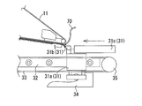
- the moving body 31 includes a main body 31a that reciprocates along the guide rail 32, a claw 31b provided on one side of the main body 31a, and one end of the claw 31b (A plate-shaped vibration preventing member 31c (for example, two plate-shaped vibration preventing members 31c) attached to the rear end is provided. Further, in the moving body 31, the traveling direction from the first reversing shaft 16 toward the guide shaft 22 (the X direction shown in FIG. 2) is opposite to the traveling direction of the first belt 11 that moves toward the first reversing shaft 16. It has become.
- the claw portion 31b is formed of a synthetic resin such as rubber.
- the claw portion 31b is formed by forming a front end portion 31b1 of a rectangular parallelepiped bar in a tapered shape, and is disposed so that one side surface 31b2 faces the label adhesion surface (outer side surface) of the first belt 11. ing.
- the label moving mechanism 30 is provided with a cam mechanism 34 on one end side (first inversion shaft 16 side) of the guide rail 32.
- the claw portion 31b of the moving body 31 is separated from the label adhesion surface of the first belt 11 from a position where the claw portion 31b of the moving body 31 comes into contact with the leading end portion of the label 1 protruding in the vicinity of the first reverse shaft 16 (FIG. In the Y direction).
- the cam mechanism 34 interference with the label 1 remaining on the first belt 11 is avoided, the back surface of the label 1 is hooked at the front end portion of the claw portion 31b, and the label 1 is pulled from the back surface to the front surface. Therefore, the label 1 can be reliably peeled from the first belt 11.
- the control unit 50 includes, for example, a computer having a CPU and a memory and a dedicated circuit, and detection signals are input from a plurality of sensors (not shown) that detect the operation state of the apparatus and the position of the adherend W. It has come to be.
- the operation unit 60 includes input devices such as a hard switch, a touch panel, a keyboard, and a mouse. The operation unit 60 is connected to the control unit 50 and receives various operations from the user.
- the memory stores a control program for driving and controlling the label sticking device, and the label sticking device is driven and controlled by the CPU executing the control program.
- the user sets the labeling device to the initial operating state. Specifically, the user pulls out the label strip 8 from the label roll 6 attached to the roll support portion 9, and temporarily bonds the back surface (adhesive layer 4) of the label strip 8 to the first belt 11. Then, the user operates the operation unit 60 to input an initial setting operation request. Upon receiving this input, the label sticking device drives only the first belt mechanism 10 and puts the label strip 8 into an initial operation state in which it is temporarily bonded to a predetermined position of the first belt 11.
- the initial operation state refers to the leading end portion of the leading label 1 of the label strip 8 temporarily bonded from one end portion of the first belt 11 (position of the reverse shaft 16). 1y (a region other than the overlapped portion 1x) is projected.
- the initial operation state may be set by, for example, the control unit 50 controlling the device based on a detection signal from a sensor (not shown) as follows.
- a sensor is installed in the vicinity of one end of the first belt 11 (position of the reversing shaft 16). This sensor transmits a detection signal to the control unit 50 when the label 1 protrudes a predetermined amount from one end of the first belt 11 (position of the reversing shaft 16).
- the control unit 50 stops the operation of the first belt 11 when receiving the detection signal from a sensor (not shown).
- a label sticking apparatus is set to an initial operation state.
- the moving body 31 of the label moving mechanism 30 is disposed at the home position (a position outside the first belt 11 and in the vicinity of the first reversing shaft 16) shown in FIG. Has been.
- the moving body 31 of the label moving mechanism 30 moves from the home position to the second belt mechanism.
- the movement is started toward the 20 guide shafts 22.
- the belt conveyor 200 that moves the second belt mechanism 20 and the adherend W also starts to operate.
- the first belt mechanism 10 is controlled to be stopped when the moving body 31 peels off the label 1 and transfers the label 1 to the second belt mechanism 20.
- the moving body 31 is pressed by the tapered front end portion 31b1 of the claw portion 31b so as to hook the back surface of the label leading end portion 1y that is peeled off from the first belt 11.
- the moving body 31 hooks the back surface of the label leading end portion 1y at the front end portion 31b1 of the claw portion 31b and moves toward the second belt mechanism 20 (in the X direction) while moving the label 1 by the cam mechanism 34. It operates in a direction away from the label adhesion surface of the first belt 11 (Y direction shown in FIG. 2) from the position where it abuts against the tip 1y. Thereby, the label 1 hooked on the claw portion 31b of the moving body 31 is peeled off from the first belt 11 while the front and back surfaces are reversed.
- the back surface contacts the side surface 31b2 of the claw portion 31b.
- the label 1 is temporarily bonded to the side surface 31b2 of the claw portion 31b of the moving body 31, and is carried to the second belt mechanism 20.
- the operation of the label 1 transferred from the first belt 11 to the moving body 31 will be described with reference to FIG.
- the moving body 31 starts to move, first, the front end portion 31b1 of the claw portion 31b comes into contact with the back surface (adhesive layer 4) of the label leading end portion 1y protruding from the first belt 11 (FIG. 4A). )reference).
- the back surface of the label 1 faces the label adhesion surface of the first belt 11 (upward in the figure).
- the moving body 31 moves in a direction away from the “label adhesion surface of the first belt 11” by the cam mechanism 34 while moving toward the guide shaft 22.
- the label 1 is picked from the first belt 11, and as shown in FIG.
- the label 1 has the front surface (overcoat layer 3) facing the label adhesive surface side of the first belt 11 (upward in the drawing) and the back surface (adhesive layer 4) facing the side surface portion 31b2 side of the claw portion 31b. Further, during the above reversing operation, the label 1 is biased toward the side surface portion 31b2 of the claw portion 31b with respect to the rear side with respect to the contact portion with the corner portion 31b3, and the rear surface on the rear side is the side surface of the claw portion 31b. 31b2 is contacted and temporarily bonded.
- the label 1 is bent between the first belt 11 and the claw portion 31b when being peeled from the first belt 11, so that the claw portion is caused by the stress. It is biased toward the side surface portion 31b2 of 31b (biased in the downward arrow direction in the figure). Thereby, the label 1 can be reliably temporarily bonded to the side surface portion 31b2 of the claw portion 31b. Further, the label 1 pulled by the claw portion 31b receives a load in a direction parallel to the adhesive surface (in the direction of arrow A in the figure) with respect to the rear label 1 adhered to the back surface thereof.
- the overcoat layer 3 is formed on the front surface of the rear label 1 adhered to the back surface (adhesive layer), it can be easily peeled off by the load in the direction of arrow A in the figure.
- angular part 31b3 protrudes ahead from the front-end part of the nail
- the label 1 is held by the moving body 31 in a state where the end portion 1y1 of the label 1 protrudes forward from the front end portion of the claw portion 31b, and is transferred to the second belt mechanism 20.
- the moving body 31 holds the label 1 held by the side surface 31b2 of the claw portion 31b between the guide shaft 22 of the second belt mechanism 20 and the pressing roller 24.
- the second belt 21 is brought into contact (temporary bonding). Specifically, the moving body 31 moves toward the guide shaft 22, thereby causing the end portion 1 y 1 of the label 1 protruding forward from the front end portion of the claw portion 31 b to the guide shaft 22 and the pressing roller 24. It is designed to be inserted between. Accordingly, the back surface of the end portion 1y1 of the label 1 held by the moving body 31 contacts the outer surface of the second belt 21, and the contacted label 1 together with the second belt 21 guides the guide shaft 22 and the pressing roller.
- the end 1y1 of the label 1 is temporarily bonded to the second belt 21.
- the label 1 behind the end portion 1y1 of the label 1 temporarily bonded to the second belt 21 is pulled by the second belt 21, and the guide While being sandwiched between the shaft 22 and the pressing roller 24, it moves away from the moving body 31 and moves to the second belt.
- the moving body 31 is provided with a plate-like vibration preventing member 31c, which prevents vibration during movement of the moving body 31 and allows the moving body 31 to operate smoothly. ing.
- the moving body 31 can carry the label 1 with high accuracy to the position of the second belt 21 between the guide shaft 22 and the pressing roller 24.
- the vibration preventing member 31 c prevents the label 1 remaining on the first belt 11 from being peeled off together with the label being transferred by the moving body 31.
- the moving body 31 returns to the above-described home position when the label 1 is moved to the second belt 21.
- the first belt mechanism 10 intermittently operates the first drive unit 13 while the moving body 31 returns to the home position, and the first belt mechanism 10 performs the first belt mechanism 10 by the distance of the leading end portion 1y of the label 1 (see FIG. 9B). 1 Belt 11 is moved. Thereby, when the mobile body 31 returns to the home position, the state shown in FIG. Thereafter, the first belt mechanism 10 and the label moving mechanism 30 repeat the above operation to peel the label 1 from the first belt 11 one by one and move the label 1 to the second belt 21.
- the labels 1 that have been peeled one by one by the label moving mechanism 30 and moved to the second belt 21 as described above are placed one by one on the second belt 21 of the second belt mechanism 20. It is in a state of being temporarily bonded with a predetermined interval. In this state, the label 1 moves toward the second inversion shaft 23. Note that the interval between the labels 1 that are temporarily bonded to the second belt 21 matches the interval between the adherends W that move on the belt conveyor 200.
- the label 1 temporarily bonded to the second belt 21 moves together with the second belt 21, and moves from the label 1 moving from the top to the second belt 21 at the position of the second reversing shaft 23.
- the peeled label 1 is pushed out from the second belt 21 and protrudes.
- the back surface of the label 1 protruding from the second belt 21 is adhered to the adherend W moving on the belt conveyor 200, and the adherend W moves in this state, whereby the label is attached to the adherend W. 1 can be pasted.
- the label 1 from the second belt 21 is prevented from being peeled off.
- a pressing mechanism as in the prior art of FIG. 10 described above becomes unnecessary, and the apparatus is not complicated.
- the traveling direction of the belt conveyor 200 and the traveling direction of the second belt 21 moving toward the second reversing shaft 22 are the same direction (a direction that is not the opposite direction).
- the moving speed of the second belt 21 and the moving speed of the belt conveyor 200 are set to be the same speed.
- a label affixing apparatus that peels off a label from a label strip formed in a strip shape by connecting a plurality of labels that do not use release paper and attaches the label to an adherend with high accuracy. Can be provided.
- the air nozzle 70 may be installed at a position outside the first belt 11 and in the vicinity of the first reversing shaft 16.
- the air nozzle 70 is connected to an air pump (not shown) that injects air in response to a control signal from the control unit 50.
- the control unit 50 drives the air pump to inject air from the air nozzle 70.
- the back surface (adhesive layer) of the front end portion 1y can be kept in an arcuate shape, and the claw portion 31b of the moving body 31 can press the back surface of the label 1 more reliably.
Landscapes
- Labeling Devices (AREA)
Applications Claiming Priority (2)
| Application Number | Priority Date | Filing Date | Title |
|---|---|---|---|
| JP2012-140935 | 2012-06-22 | ||
| JP2012140935A JP5996295B2 (ja) | 2012-06-22 | 2012-06-22 | ラベル貼付装置 |
Publications (1)
| Publication Number | Publication Date |
|---|---|
| WO2013191233A1 true WO2013191233A1 (fr) | 2013-12-27 |
Family
ID=49768827
Family Applications (1)
| Application Number | Title | Priority Date | Filing Date |
|---|---|---|---|
| PCT/JP2013/066915 Ceased WO2013191233A1 (fr) | 2012-06-22 | 2013-06-20 | Dispositif de pose d'étiquettes |
Country Status (2)
| Country | Link |
|---|---|
| JP (1) | JP5996295B2 (fr) |
| WO (1) | WO2013191233A1 (fr) |
Cited By (3)
| Publication number | Priority date | Publication date | Assignee | Title |
|---|---|---|---|---|
| WO2014196334A1 (fr) * | 2013-06-04 | 2014-12-11 | 株式会社ウイル・コーポレーション | Dispositif d'application d'étiquettes |
| WO2015129397A1 (fr) * | 2014-02-25 | 2015-09-03 | 株式会社ウイル・コーポレーション | Dispositif d'application d'étiquettes |
| JP2016037311A (ja) * | 2014-08-08 | 2016-03-22 | フレンド株式会社 | ラベル貼付装置 |
Families Citing this family (2)
| Publication number | Priority date | Publication date | Assignee | Title |
|---|---|---|---|---|
| KR101772753B1 (ko) * | 2015-08-24 | 2017-08-29 | 허인애 | 휴대단말기 포장박스의 마감스티커 부착장치 |
| CN105600052A (zh) * | 2016-01-26 | 2016-05-25 | 苏州隆成电子设备有限公司 | 接标台 |
Citations (8)
| Publication number | Priority date | Publication date | Assignee | Title |
|---|---|---|---|---|
| JPH02129012U (fr) * | 1989-03-28 | 1990-10-24 | ||
| JPH06122436A (ja) * | 1992-10-07 | 1994-05-06 | Tamagawa Seiki Co Ltd | ラベル貼着方法 |
| US5895552A (en) * | 1994-09-14 | 1999-04-20 | Osaka Sealing Printing Co., Ltd. | Bonding apparatus for cutting label continuum having labels formed successively and bonding label to object |
| WO2000014001A2 (fr) * | 1998-09-02 | 2000-03-16 | Add-On International B.V. | Procede et appareil de fixation d'etiquettes |
| JP3163087U (ja) * | 2010-07-09 | 2010-09-30 | 英二郎 滑川 | 台紙無しラベル剥離・排出手段 |
| WO2011038710A1 (fr) * | 2009-09-29 | 2011-04-07 | X-Label Gmbh - Holding | Pile d'étiquettes et procédé pour appliquer des étiquettes autocollantes sur des contenants de produits |
| JP2012091910A (ja) * | 2010-10-27 | 2012-05-17 | Towa Seiko Kk | ラベル剥離機 |
| WO2012086254A1 (fr) * | 2010-12-24 | 2012-06-28 | ランベル合同会社 | Dispositif d'application automatique d'étiquette et procédé d'application automatique d'étiquette |
-
2012
- 2012-06-22 JP JP2012140935A patent/JP5996295B2/ja not_active Expired - Fee Related
-
2013
- 2013-06-20 WO PCT/JP2013/066915 patent/WO2013191233A1/fr not_active Ceased
Patent Citations (8)
| Publication number | Priority date | Publication date | Assignee | Title |
|---|---|---|---|---|
| JPH02129012U (fr) * | 1989-03-28 | 1990-10-24 | ||
| JPH06122436A (ja) * | 1992-10-07 | 1994-05-06 | Tamagawa Seiki Co Ltd | ラベル貼着方法 |
| US5895552A (en) * | 1994-09-14 | 1999-04-20 | Osaka Sealing Printing Co., Ltd. | Bonding apparatus for cutting label continuum having labels formed successively and bonding label to object |
| WO2000014001A2 (fr) * | 1998-09-02 | 2000-03-16 | Add-On International B.V. | Procede et appareil de fixation d'etiquettes |
| WO2011038710A1 (fr) * | 2009-09-29 | 2011-04-07 | X-Label Gmbh - Holding | Pile d'étiquettes et procédé pour appliquer des étiquettes autocollantes sur des contenants de produits |
| JP3163087U (ja) * | 2010-07-09 | 2010-09-30 | 英二郎 滑川 | 台紙無しラベル剥離・排出手段 |
| JP2012091910A (ja) * | 2010-10-27 | 2012-05-17 | Towa Seiko Kk | ラベル剥離機 |
| WO2012086254A1 (fr) * | 2010-12-24 | 2012-06-28 | ランベル合同会社 | Dispositif d'application automatique d'étiquette et procédé d'application automatique d'étiquette |
Cited By (3)
| Publication number | Priority date | Publication date | Assignee | Title |
|---|---|---|---|---|
| WO2014196334A1 (fr) * | 2013-06-04 | 2014-12-11 | 株式会社ウイル・コーポレーション | Dispositif d'application d'étiquettes |
| WO2015129397A1 (fr) * | 2014-02-25 | 2015-09-03 | 株式会社ウイル・コーポレーション | Dispositif d'application d'étiquettes |
| JP2016037311A (ja) * | 2014-08-08 | 2016-03-22 | フレンド株式会社 | ラベル貼付装置 |
Also Published As
| Publication number | Publication date |
|---|---|
| JP2014005015A (ja) | 2014-01-16 |
| JP5996295B2 (ja) | 2016-09-21 |
Similar Documents
| Publication | Publication Date | Title |
|---|---|---|
| CN103068684B (zh) | 片材剥离装置及剥离方法以及片材粘贴装置及粘贴方法 | |
| JP5996295B2 (ja) | ラベル貼付装置 | |
| WO2012086254A1 (fr) | Dispositif d'application automatique d'étiquette et procédé d'application automatique d'étiquette | |
| CN103568591B (zh) | 图像形成装置 | |
| WO2010101101A1 (fr) | Dispositif d'application automatique d'étiquettes et procédé d'application automatique d'étiquettes | |
| JP5606210B2 (ja) | シート貼付装置および貼付方法 | |
| JP2012176775A (ja) | シート剥離装置および剥離方法 | |
| JP3093189B2 (ja) | ラベル貼付装置およびラベル貼付方法 | |
| JP6412442B2 (ja) | シート供給装置および供給方法 | |
| JP2012035888A (ja) | シート剥離装置および剥離方法ならびにシート貼付装置および貼付方法 | |
| JP5015629B2 (ja) | ラベル貼付装置及びラベル貼付方法 | |
| CN115552588A (zh) | 片粘贴装置及片粘贴方法 | |
| JP5775735B2 (ja) | シート貼付装置および貼付方法 | |
| JP2014240306A (ja) | シート貼付装置 | |
| JP5378621B1 (ja) | ラベル貼付装置及びラベル貼付方法 | |
| JP2007230566A (ja) | ラベル貼付装置およびラベル貼付方法 | |
| JP2014141267A (ja) | ラベル貼付装置及びラベル貼付方法 | |
| JP5771661B2 (ja) | ラベル貼付装置 | |
| JP6530936B2 (ja) | シート供給装置およびシート供給方法 | |
| JP4822520B2 (ja) | ラベル貼付装置 | |
| WO2015129397A1 (fr) | Dispositif d'application d'étiquettes | |
| JP5667833B2 (ja) | シート貼付装置および貼付方法 | |
| JP2014151953A (ja) | シート貼付装置およびシート貼付方法 | |
| JP4526878B2 (ja) | 非接触データキャリア部材取付方法及び装置 | |
| JP5627100B2 (ja) | 接着シート原反 |
Legal Events
| Date | Code | Title | Description |
|---|---|---|---|
| 121 | Ep: the epo has been informed by wipo that ep was designated in this application |
Ref document number: 13806697 Country of ref document: EP Kind code of ref document: A1 |
|
| NENP | Non-entry into the national phase |
Ref country code: DE |
|
| 122 | Ep: pct application non-entry in european phase |
Ref document number: 13806697 Country of ref document: EP Kind code of ref document: A1 |