WO2012090914A1 - Procédé de spectrométrie de masse, spectromètre de masse et système de spectrométrie de masse - Google Patents
Procédé de spectrométrie de masse, spectromètre de masse et système de spectrométrie de masse Download PDFInfo
- Publication number
- WO2012090914A1 WO2012090914A1 PCT/JP2011/080024 JP2011080024W WO2012090914A1 WO 2012090914 A1 WO2012090914 A1 WO 2012090914A1 JP 2011080024 W JP2011080024 W JP 2011080024W WO 2012090914 A1 WO2012090914 A1 WO 2012090914A1
- Authority
- WO
- WIPO (PCT)
- Prior art keywords
- mass
- ion introduction
- sample
- mass spectrometer
- introduction part
- Prior art date
- Legal status (The legal status is an assumption and is not a legal conclusion. Google has not performed a legal analysis and makes no representation as to the accuracy of the status listed.)
- Ceased
Links
Images




Classifications
-
- H—ELECTRICITY
- H01—ELECTRIC ELEMENTS
- H01J—ELECTRIC DISCHARGE TUBES OR DISCHARGE LAMPS
- H01J49/00—Particle spectrometers or separator tubes
- H01J49/02—Details
- H01J49/04—Arrangements for introducing or extracting samples to be analysed, e.g. vacuum locks; Arrangements for external adjustment of electron- or ion-optical components
-
- H—ELECTRICITY
- H01—ELECTRIC ELEMENTS
- H01J—ELECTRIC DISCHARGE TUBES OR DISCHARGE LAMPS
- H01J49/00—Particle spectrometers or separator tubes
- H01J49/02—Details
- H01J49/04—Arrangements for introducing or extracting samples to be analysed, e.g. vacuum locks; Arrangements for external adjustment of electron- or ion-optical components
- H01J49/0404—Capillaries used for transferring samples or ions
-
- H—ELECTRICITY
- H01—ELECTRIC ELEMENTS
- H01J—ELECTRIC DISCHARGE TUBES OR DISCHARGE LAMPS
- H01J49/00—Particle spectrometers or separator tubes
- H01J49/02—Details
- H01J49/04—Arrangements for introducing or extracting samples to be analysed, e.g. vacuum locks; Arrangements for external adjustment of electron- or ion-optical components
- H01J49/0468—Arrangements for introducing or extracting samples to be analysed, e.g. vacuum locks; Arrangements for external adjustment of electron- or ion-optical components with means for heating or cooling the sample
Definitions
- the present invention relates to a mass spectrometry method, a mass spectrometer, and a mass spectrometry system.
- DART is a method in which protons generated by collision of atoms or molecules in an electronically excited state with water in the atmosphere and penning ionization are added to a sample and ionized.
- protons generated by collision of atoms or molecules in an electronically excited state with water in the atmosphere and penning ionization are added to a sample and ionized.
- the sample M can be ionized as follows.
- He (2 3 S) + H 2 O ⁇ H 2 O + * + He (1 1 S) + e ⁇ H 2 O + * + H 2 O ⁇ H 3 O + + OH * H 3 O + + nH 2 O ⁇ [(H 2 O) n H] + [(H 2 O) n H] + + M ⁇ MH + + nH 2 O DESI is a method of desorbing ions by attaching an ionized solvent to a sample.
- An object of the present invention is to provide a mass spectrometry method, a mass spectrometer, and a mass spectrometry system.
- the mass spectrometry method of the present invention is a method of introducing mass generated by introducing ions generated from a sample into a mass spectrometer using DART or DESI, wherein the mass spectrometer is an ion introduction unit for introducing the ions.
- the ion introduction part is heated at a predetermined timing.
- the mass spectrometric method of the present invention is a method for heating a sample to generate a gas, and using DART to introduce ions generated from the gas into a mass spectrometer for mass analysis, wherein the mass spectrometer is And an ion introduction part for introducing the ions, and the ion introduction part is heated at a predetermined timing.
- the mass spectrometry method of the present invention is a method of performing mass analysis by using DART and introducing ions generated from a gas generated by heating a sample into a mass spectrometer, wherein the mass spectrometer analyzes the ions.
- An ion introduction part to be introduced is provided, and the ion introduction part is heated at a predetermined timing.
- the mass spectrometer of the present invention is a mass spectrometer used for mass analysis of ions generated from a sample using DART or DESI, and heats the ion introduction part for introducing the ions and the ion introduction part. Has heating means.
- the mass spectrometry system of the present invention includes a DART ion source and / or a DESI ion source and the mass spectrometer of the present invention.
- the mass spectrometry method and mass spectrometer which can suppress the contamination of the ion introduction part by the ion produced
- FIG. 1 shows an example of the mass spectrometry method of the present invention.
- the DART ion source 10 is used to irradiate the sample S attached to the glass rod R with protons generated by penning ionization by colliding helium He (2 3 S) in a metastable excited state with water in the atmosphere.
- the generated ions are introduced into the mass spectrometer 20 for mass analysis.
- a voltage is applied to the resistance heating wire 21a using a power source (not shown), so that the ion introduction tube 21 is connected. Can be heated. Thereby, contamination of the ion introduction tube 21 by ions generated from the sample S can be suppressed.
- the inside of the ion introduction tube 21 is depressurized by a compressor (not shown).
- timing which heats the iontophoresis tube 21 is not specifically limited.
- the ion introduction tube 21 may be heated after mass analysis of ions generated from the sample S.
- the ions generated from the sample S are subjected to mass analysis, even if the ions generated from the sample S adhere to the ion introduction tube 21, the ions generated from the sample S are subjected to mass analysis, and then to the ion introduction tube 21.
- the attached ions can be removed.
- contamination of the ion introduction tube 21 by ions generated from the sample S can be suppressed.
- the ions generated from the sample S may be subjected to mass spectrometry while the ion introduction tube 21 is heated.
- generated from the sample S can be suppressed.
- contamination of the ion introduction tube 21 by ions generated from the sample S can be suppressed.
- the ion introduction tube 21 may be heated even after mass analysis of ions generated from the sample S.
- the resistance heating wire 21a is usually wound around the side of the ion introduction tube 21 where the ions are introduced.
- the temperature of the inner wall of the ion introduction tube 21 when the ion introduction tube 21 is heated is usually 50 to 500 ° C., preferably 100 to 300 ° C. If the temperature of the inner wall of the ion introduction tube 21 is less than 50 ° C., the ion introduction tube 21 may be contaminated by ions generated from the sample S. If the temperature exceeds 500 ° C., the mass spectrometer 20 may be adversely affected. There is.
- the material constituting the iontophoresis tube 21 is not particularly limited as long as it has heat resistance, and examples thereof include ceramics, glass, Teflon (registered trademark), stainless steel, niobium steel, and tantalum steel.
- the inner surface of the ion introduction tube 21 may be coated with fluorine resin, polyether ether ketone, silicone resin or the like. Thereby, the adhesion of ions generated from the sample S to the inner wall of the ion introduction tube 21 can be further suppressed.
- a heat insulating sheet 22 may be installed around the ion introduction tube 21 (see FIG. 2). Thereby, volatilization of the sample S due to heat derived from the ion introduction tube 21 can be suppressed. As a result, the analysis accuracy of the sample S can be improved.
- the material constituting the heat insulating sheet 22 is not particularly limited, and examples thereof include ceramics and fluororesin.
- the material constituting the resistance heating wire 21a is not particularly limited, but a metal heating element such as an iron-chromium-aluminum alloy or nickel-chromium alloy; a refractory metal heating element such as platinum, molybdenum, tantalum, or tungsten; Examples thereof include non-metallic heating elements such as silicon carbide, molybdenum-silicite, and carbon.
- a metal heating element such as an iron-chromium-aluminum alloy or nickel-chromium alloy
- a refractory metal heating element such as platinum, molybdenum, tantalum, or tungsten
- non-metallic heating elements such as silicon carbide, molybdenum-silicite, and carbon.
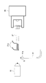
- a glass tube 21 ′ (see FIG. 3) on which an ITO film 21a ′ is formed is used, and a power source (not shown) is used to make the ITO film 21a ′.
- the glass tube 21 ′ may be heated by applying a voltage to. Thereby, it becomes easy to control the temperature of the inner wall of the glass tube 21 ′, and it becomes easy to confirm the adhesion of ions generated from the sample S to the glass tube 21 ′.
- the iontophoresis tube 21 does not specifically limit as a method to heat the iontophoresis tube 21, The method to heat using a ceramic fiber heater, The method to heat by irradiating a microwave, The method to heat using a hot air fan, etc. are mentioned. .
- the ion introduction tube 21 instead of heating the ion introduction tube 21, the ion introduction tube 21 may be removed and the ion introduction port may be directly heated.
- metastable excited state instead of helium He (2 3 S) in the metastable excited state, neon in the metastable excited state, argon in the metastable excited state, nitrogen in the metastable excited state, or the like may be used.
- the sample S is not particularly limited as long as ions can be generated using the DART ion source 10, and examples thereof include organic compounds.
- a DESI ion source may be used to attach ions to a sample and desorb ions.
- the solvent to be ionized is not particularly limited, and examples thereof include methanol, methanol aqueous solution, acetonitrile, acetonitrile aqueous solution and the like.
- the solvent to be ionized may contain an acidic substance or a basic substance.
- the sample is not particularly limited as long as ions can be generated using a DESI ion source, and examples thereof include organic compounds.
- the DART ion source 10 is used as a gas generated by heating the sample S to generate protons produced by penetrating ionization by colliding helium He (2 3 S) in a metastable excited state with water in the atmosphere.
- the ions generated by irradiation may be introduced into the mass spectrometer 20 for mass analysis.
- the sample S contains a polymer compound
- ions generated from a gas generated by thermal decomposition of the polymer compound are introduced into the mass spectrometer 20, so that the structure of the polymer compound can be analyzed. it can. Further, by changing the temperature at which the sample S is heated continuously or stepwise, ions generated from the gas generated by heating the sample S at each temperature can be introduced into the mass spectrometer 20.
- the method of heating the sample S to generate gas is not particularly limited, but a method of heating the sample S by flowing a current through a resistance heating wire to generate gas, and heating the sample S using a ceramic fiber heater. And a method of generating gas by irradiating the sample S with microwaves and heating it, and a method of generating gas by heating the sample S using a hot air blower.
- FIG. 4 shows an example of a method for generating a gas by heating the sample S by passing an electric current through a resistance heating wire.
- the heating device 30 is shown as a cross-sectional view.
- the pot 31 After putting the sample S into the pot 31, the pot 31 is held on the pot holding member 32. At this time, since the resistance heating wire 32a is wound around the pot holding member 32, the pot holding member 32 can be heated by applying a voltage to the resistance heating wire 32a using a power source (not shown). . Thereby, the sample S can be heated and gas can be generated.
- a heat insulating member 33 is installed around the pot holding member 32.
- the temperature of the pot holding member 32 when heating the sample S is usually 50 to 1200 ° C., preferably 200 to 1000 ° C. If the temperature of the pot holding member 32 is less than 50 ° C, it may be difficult to thermally decompose the polymer compound. If the temperature exceeds 1200 ° C, the resistance heating wire 32a may be cut.
- the material constituting the pot 31 is not particularly limited as long as it has heat resistance, and examples thereof include glass and quartz.
- the material constituting the pot holding member 32 is not particularly limited as long as it has heat resistance, and examples thereof include ceramics, glass, stainless steel, niobium steel, and tantalum steel.
- the material constituting the resistance heating wire 32a is not particularly limited, but a metal heating element such as an iron-chromium-aluminum alloy or nickel-chromium alloy; a refractory metal heating element such as platinum, molybdenum, tantalum, or tungsten; Examples thereof include non-metallic heating elements such as silicon carbide, molybdenum-silicite, and carbon.
- a metal heating element such as an iron-chromium-aluminum alloy or nickel-chromium alloy
- a refractory metal heating element such as platinum, molybdenum, tantalum, or tungsten
- non-metallic heating elements such as silicon carbide, molybdenum-silicite, and carbon.
- the material constituting the heat insulating member 33 is not particularly limited as long as it has heat resistance and heat insulating properties, and examples thereof include ceramics, glass, stainless steel, niobium steel, and tantalum steel.
- the resistance heating wire 31a may be wound around the pot 31 (see FIG. 5).
- FIG. 5 only the heating device 30 ′ is shown as a cross-sectional view.
- a heat source may be installed below the pot 31 without wrapping the resistance heating wire 32 a around the pot holding member 32.
- the heat source is not particularly limited, and examples thereof include a ceramic heater and a cartridge heater embedded in the plate.
- the material constituting the plate is not particularly limited as long as the thermal conductivity is good, and examples thereof include copper and aluminum.
- FIG. 6 shows another example of a method of generating gas by heating the sample S by passing an electric current through the resistance heating wire.
- the sample S is attached to the resistance heating wire 41a supported by the resistance heating wire support member 41, the sample S is heated by applying a voltage to the resistance heating wire 41a using a power source (not shown). Gas can be generated.
- the temperature of the resistance heating wire 41a when heating the sample S is usually 50 to 1200 ° C, preferably 200 to 1000 ° C. When the temperature of the resistance heating wire 41a is less than 50 ° C, it may be difficult to thermally decompose the polymer compound. When the temperature exceeds 1200 ° C, the resistance heating wire 41a may be cut.
- the resistance heating wire support member 41 is not particularly limited as long as it has heat resistance and insulation properties, and examples thereof include ceramics and glass.
- the material constituting the resistance heating wire 41a is not particularly limited, but a metal heating element such as an iron-chromium-aluminum alloy or a nickel-chromium alloy; a refractory metal heating element such as platinum, molybdenum, tantalum, or tungsten; Examples thereof include non-metallic heating elements such as silicon carbide, molybdenum-silicite, and carbon.
- a metal heating element such as an iron-chromium-aluminum alloy or a nickel-chromium alloy
- a refractory metal heating element such as platinum, molybdenum, tantalum, or tungsten
- non-metallic heating elements such as silicon carbide, molybdenum-silicite, and carbon.
- the DART ion source 10 is used to irradiate the sample S with protons generated by penning ionization by colliding helium He (2 3 S) in a metastable excited state with water in the atmosphere.
- the ions generated in this manner may be introduced into the mass spectrometer 20 for mass analysis.
- the sample S contains a polymer compound
- ions generated from a gas generated by thermal decomposition of the polymer compound are introduced into the mass spectrometer 20, so that the structure of the polymer compound can be analyzed. it can.
- the method of heating the sample S is not particularly limited, but a method of heating the sample S by passing a current through a resistance heating wire, a method of heating the sample S using a ceramic fiber heater, and irradiating the sample S with microwaves. And a method of heating the sample S using a hot air fan.
- FIG. 7 shows an example of a method for heating the sample S by passing a current through the resistance heating wire.
- the sample S After attaching the sample S to the resistance heating wire 41a supported by the resistance heating wire support member 41, the sample S is heated by applying a voltage to the resistance heating wire 41a using a power source (not shown). Can do.
- the temperature of the resistance heating wire 41a when heating the sample S is usually 50 to 1200 ° C, preferably 200 to 1000 ° C. When the temperature at which the sample S is heated is less than 50 ° C., it may be difficult to thermally decompose the polymer compound. When the temperature exceeds 1200 ° C., the resistance heating wire 41a may be cut.
- Example 1 A glass rod was immersed in a 5% by mass methanol solution of polyethylene glycol having an average molecular weight of 400, and polyethylene glycol was adhered to the glass rod R as Sample S.
- generated from polyethyleneglycol was carried out using the mass spectrometry method of FIG. Specifically, first, protons generated by penning ionization by colliding metastable helium He (2 3 S) with water in the atmosphere using the DART ion source 10 are attached to the glass rod R. The ions generated by irradiation of the polyethylene glycol were introduced into the mass spectrometer 20 and subjected to mass analysis (1.5-3 min). Next, the DART ion source 10 was stopped (3 to 6 minutes). Further, the ion introduction tube 21 was heated by passing a current of 4.5 A through the resistance heating wire 21a (5 to 6 min). At this time, the temperature of the inner wall of the ion introduction tube 21 rose from 19 to 23 ° C. to 170 to 270 ° C.
- DART SVP (made by Ion Sense) was used as the DART ion source 10, and the set temperature of the gas heater was set to 500 ° C.
- MicrOTOFQII (manufactured by Bruker Daltonics) was used, and the measurement mode was set to positive ion mode.
- a ceramic tube having an outer diameter of 6.2 mm, an inner diameter of 4.7 mm, and a length of 94 mm is used as the ion introduction tube 21, and the resistance heating wire 21 a is wound around a region 35 mm from the ion introduction side. It was. At this time, a nichrome wire having a diameter of 0.26 mm was used as the resistance heating wire 21a.
- FIGS. 9A and 9B show mass spectra at 2.0 min and 5.2 min of the mass chromatogram of FIG. 7, respectively.
- FIG. 9 shows that a peak derived from polyethylene glycol is present in the mass spectrum at 2.0 min and 5.2 min in the mass chromatogram of FIG. For this reason, from FIG. 8, when mass analysis is performed on ions generated from polyethylene glycol, ions generated from polyethylene glycol are attached to the ion introduction tube 21. It turns out that the ion produced
- Example 2 A glass rod R was immersed in a 5% by mass methanol solution of polyethylene glycol having an average molecular weight of 400, and polyethylene glycol was adhered to the glass rod R as a sample S.
- generated from polyethyleneglycol was carried out using the mass spectrometry method of FIG. Specifically, first, protons generated by penning ionization by colliding metastable helium He (2 3 S) with water in the atmosphere using the DART ion source 10 are attached to the glass rod R. The ions generated by irradiation of the polyethylene glycol were introduced into the mass spectrometer 20 and subjected to mass analysis (1.5 to 3.2 min). The ion introduction tube 21 was heated by supplying a current of 4.5 A to the resistance heating wire 21a (1 to 4 minutes). At this time, the temperature of the inner wall of the ion introduction tube 21 rose from 19 to 23 ° C. to 170 to 270 ° C.
- the DART ion source 10 was stopped (3.2 to 6 min). Further, the current flowing through the resistance heating wire 21a was set to 0 A (4 to 5 minutes). Further, the ion introduction tube 21 was heated by passing a current of 4.5 A through the resistance heating wire 21a (5 to 6 min). At this time, the temperature of the inner wall of the ion introduction tube 21 increased to 170 to 270 ° C.
- DART SVP (made by Ion Sense) was used as the DART ion source 10, and the set temperature of the gas heater was set to 500 ° C.
- MicrOTOFQII (manufactured by Bruker Daltonics) was used, and the measurement mode was set to positive ion mode.
- a ceramic tube having an outer diameter of 6.2 mm, an inner diameter of 4.7 mm, and a length of 94 mm is used as the ion introduction tube 21, and the resistance heating wire 21 a is wound around a region 35 mm from the ion introduction side. It was. At this time, a nichrome wire having a diameter of 0.26 mm was used as the resistance heating wire 21a.
- 11 (a) and 11 (b) show mass spectra at 2.0 min and 5.2 min of the mass chromatogram of FIG. 10, respectively.
- Example 3 As sample S, polypropylene was put in a pot 31 made of heat-resistant glass, and then the pot 31 was held on a pot holding member 32.
- ions generated from the gas generated by heating the polypropylene were subjected to mass spectrometry. Specifically, first, by using the DART ion source 10, protons produced by penning ionization by colliding helium He (2 3 S) in a metastable excited state with water in the atmosphere are heated by polypropylene. Ions generated by irradiation of the generated gas were introduced into the mass spectrometer 20 and subjected to mass analysis (1 to 3 min). At this time, the pot holding member 32 was heated to 570 ° C. by passing a current of 4.5 A through the resistance heating wire 32 a.
- the DART ion source 10 was stopped (3 to 7.8 min). Further, the ion introduction tube 21 was heated by passing a current of 4.5 A through the resistance heating wire 21a (5.6 to 7.8 min). At this time, the temperature of the inner wall of the ion introduction tube 21 rose from 19 to 23 ° C. to 170 to 270 ° C.
- DART SVP made by Ion Sense
- the set temperature of the gas heater was set to 500 ° C.
- MicrOTOFQII manufactured by Bruker Daltonics
- the measurement mode was set to positive ion mode.
- a ceramic tube having an outer diameter of 6.2 mm, an inner diameter of 4.7 mm, and a length of 94 mm is used as the ion introduction tube 21, and the resistance heating wire 21 a is wound around a region 35 mm from the ion introduction side. It was.
- a nichrome wire having a diameter of 0.26 mm was used as the resistance heating wire 21a. Further, a ceramic pot holding member 32 was used, a nichrome wire having a diameter of 0.32 mm was used as the resistance heating wire 32a, and a ceramic heat insulating member 33 was used.
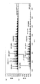
- FIG. 13 shows mass spectra at 1.8 min and 5.8 min of the mass chromatogram of FIG.
- FIG. 13 shows that peaks derived from polypropylene are present in the mass spectrum at 1.8 min and 5.8 min in the mass chromatogram of FIG. Therefore, from FIG. 12, when mass analysis is performed on ions generated from a gas generated by heating polypropylene, ions generated from the gas generated by heating polypropylene adhere to the ion introduction tube 21. It can be seen that after mass analysis of ions generated from the gas generated by heating, the ions generated from the gas generated by heating the polypropylene adhering to the ion introduction tube 21 can be removed. Accordingly, after mass analysis of ions generated from the gas generated by heating polypropylene, the ion introduction tube 21 is heated to heat the ion introduction tube 21 by ions generated from the gas generated by heating polypropylene. It can be seen that contamination can be suppressed.
Landscapes
- Chemical & Material Sciences (AREA)
- Analytical Chemistry (AREA)
- Other Investigation Or Analysis Of Materials By Electrical Means (AREA)
- Electron Tubes For Measurement (AREA)
Abstract
Priority Applications (3)
| Application Number | Priority Date | Filing Date | Title |
|---|---|---|---|
| JP2012550926A JPWO2012090914A1 (ja) | 2010-12-27 | 2011-12-26 | 質量分析方法、質量分析計及び質量分析システム |
| US13/997,714 US20130284915A1 (en) | 2010-12-27 | 2011-12-26 | Mass spectrometry method, mass spectrometer, and mass spectrometry system |
| EP11853122.7A EP2660590A1 (fr) | 2010-12-27 | 2011-12-26 | Procédé de spectrométrie de masse, spectromètre de masse et système de spectrométrie de masse |
Applications Claiming Priority (2)
| Application Number | Priority Date | Filing Date | Title |
|---|---|---|---|
| JP2010290743 | 2010-12-27 | ||
| JP2010-290743 | 2010-12-27 |
Publications (1)
| Publication Number | Publication Date |
|---|---|
| WO2012090914A1 true WO2012090914A1 (fr) | 2012-07-05 |
Family
ID=46383018
Family Applications (1)
| Application Number | Title | Priority Date | Filing Date |
|---|---|---|---|
| PCT/JP2011/080024 Ceased WO2012090914A1 (fr) | 2010-12-27 | 2011-12-26 | Procédé de spectrométrie de masse, spectromètre de masse et système de spectrométrie de masse |
Country Status (4)
| Country | Link |
|---|---|
| US (1) | US20130284915A1 (fr) |
| EP (1) | EP2660590A1 (fr) |
| JP (1) | JPWO2012090914A1 (fr) |
| WO (1) | WO2012090914A1 (fr) |
Cited By (3)
| Publication number | Priority date | Publication date | Assignee | Title |
|---|---|---|---|---|
| CN103515185A (zh) * | 2013-09-18 | 2014-01-15 | 东华理工大学 | 一种质谱检测果汁样品中农残的离子化装置及检测方法 |
| US9824875B2 (en) | 2014-06-15 | 2017-11-21 | Ionsense, Inc. | Apparatus and method for generating chemical signatures using differential desorption |
| JP2021053404A (ja) * | 2015-03-06 | 2021-04-08 | マイクロマス ユーケー リミテッド | 急速蒸発イオン化質量分析(「reims」)装置に連結されたイオンアナライザのための流入器具 |
Families Citing this family (15)
| Publication number | Priority date | Publication date | Assignee | Title |
|---|---|---|---|---|
| US8207497B2 (en) | 2009-05-08 | 2012-06-26 | Ionsense, Inc. | Sampling of confined spaces |
| WO2012090915A1 (fr) * | 2010-12-27 | 2012-07-05 | 株式会社資生堂 | Procédé de spectrométrie de masse, dispositif de génération d'ions et système de spectromètre de masse |
| US8822949B2 (en) | 2011-02-05 | 2014-09-02 | Ionsense Inc. | Apparatus and method for thermal assisted desorption ionization systems |
| US9875884B2 (en) * | 2015-02-28 | 2018-01-23 | Agilent Technologies, Inc. | Ambient desorption, ionization, and excitation for spectrometry |
| EP3265822B1 (fr) | 2015-03-06 | 2021-04-28 | Micromass UK Limited | Analyse tissulaire par spectrométrie de masse ou par spectrométrie de mobilité ionique |
| WO2016142691A1 (fr) * | 2015-03-06 | 2016-09-15 | Micromass Uk Limited | Analyse par spectrométrie de masse par ionisation par évaporation rapide (« reims ») et spectrométrie de masse par ionisation par electronébulisation par désorption (« desi-ms ») d'écouvillons et d'échantillons de biopsie |
| WO2016145041A1 (fr) * | 2015-03-09 | 2016-09-15 | Purdue Research Foundation | Systèmes et procédés pour ionisation de relais |
| US9899196B1 (en) | 2016-01-12 | 2018-02-20 | Jeol Usa, Inc. | Dopant-assisted direct analysis in real time mass spectrometry |
| US10636640B2 (en) | 2017-07-06 | 2020-04-28 | Ionsense, Inc. | Apparatus and method for chemical phase sampling analysis |
| WO2019231859A1 (fr) | 2018-06-01 | 2019-12-05 | Ionsense Inc. | Appareil et procédé de réduction d'effets de matrice lors de l'ionisation d'un échantillon |
| CN110208039B (zh) * | 2019-06-27 | 2021-12-10 | 山东安准智能科技有限公司 | 一种取样器、快速加热进样系统及快速检测方法 |
| JP7705845B2 (ja) | 2019-10-28 | 2025-07-10 | イオンセンス インコーポレイテッド | 大気リアルタイムイオン化 |
| CN113791135A (zh) * | 2020-05-25 | 2021-12-14 | 华质泰科生物技术(北京)有限公司 | 一种快速检测样品中有机砷化合物的方法 |
| US11913861B2 (en) | 2020-05-26 | 2024-02-27 | Bruker Scientific Llc | Electrostatic loading of powder samples for ionization |
| EP4679053A1 (fr) * | 2024-07-09 | 2026-01-14 | Netzsch-Gerätebau GmbH | Tube et système d'analyse |
Citations (5)
| Publication number | Priority date | Publication date | Assignee | Title |
|---|---|---|---|---|
| JP2002170685A (ja) * | 2000-11-29 | 2002-06-14 | Canon Inc | 導電性液晶素子及びこれを用いた有機エレクトロルミネッセンス素子 |
| JP2004340961A (ja) * | 2003-05-13 | 2004-12-02 | Berkin Bv | 質量流量計 |
| JP2008180659A (ja) | 2007-01-26 | 2008-08-07 | Jeol Ltd | 大気圧イオン化法および試料保持装置 |
| WO2010012987A2 (fr) * | 2008-07-28 | 2010-02-04 | Micromas Uk Limited | Source d'ions à décharge luminescente |
| JP2010504504A (ja) * | 2006-09-25 | 2010-02-12 | エムディーエス アナリティカル テクノロジーズ, ア ビジネス ユニット オブ エムディーエス インコーポレイテッド, ドゥーイング ビジネス スルー イッツ サイエックス ディビジョン | 質量分析計とともに使用するための複数の試料供給源、ならびにそのための装置、デバイスおよび方法 |
Family Cites Families (14)
| Publication number | Priority date | Publication date | Assignee | Title |
|---|---|---|---|---|
| US4531056A (en) * | 1983-04-20 | 1985-07-23 | Yale University | Method and apparatus for the mass spectrometric analysis of solutions |
| GB8503125D0 (en) * | 1985-02-07 | 1985-03-13 | Sherritt Gordon Mines Ltd | Quadrupole mass spectrometers |
| US4804839A (en) * | 1987-07-07 | 1989-02-14 | Hewlett-Packard Company | Heating system for GC/MS instruments |
| JP2913924B2 (ja) * | 1991-09-12 | 1999-06-28 | 株式会社日立製作所 | 質量分析の方法および装置 |
| WO2000040886A1 (fr) * | 1998-12-31 | 2000-07-13 | Bouygues Offshore | Dispositif et procede thermique d'isolation d'au moins une conduite sous-marine a grande profondeur |
| DE60044892D1 (de) * | 1999-09-20 | 2010-10-14 | Hitachi Ltd | Ionenquelle, Massenspektrometer, Massenspektrometrie und Überwachungssystem |
| US6649907B2 (en) * | 2001-03-08 | 2003-11-18 | Wisconsin Alumni Research Foundation | Charge reduction electrospray ionization ion source |
| EP1394836B1 (fr) * | 2001-06-08 | 2011-09-21 | Japan Science and Technology Corporation | Dispositif de spectrometrie de masse de liquide refroidisseur |
| JP4337584B2 (ja) * | 2004-03-10 | 2009-09-30 | 株式会社日立製作所 | 質量分析装置及びイオン源 |
| CA2480549A1 (fr) * | 2004-09-15 | 2006-03-15 | Phytronix Technologies Inc. | Source d'ionisation pour spectrometre de masse |
| US7423721B2 (en) * | 2004-12-15 | 2008-09-09 | Asml Netherlands B.V. | Lithographic apparatus |
| US20060221295A1 (en) * | 2005-04-04 | 2006-10-05 | Lear Corporation | Lcd heater system |
| CA2609802A1 (fr) * | 2005-05-27 | 2006-12-07 | Ionwerks, Inc. | Spectrometre de masse a temps de vol a mobilite ionique multifaisceau presentant des extraction ionique bipolaire et detection de zwitterions |
| KR20080017929A (ko) * | 2006-08-23 | 2008-02-27 | 한국표준과학연구원 | 잔류기체분석기에 의한 이온게이지의 방출기체 조성과 압력측정장치 및 그 측정방법 |
-
2011
- 2011-12-26 JP JP2012550926A patent/JPWO2012090914A1/ja active Pending
- 2011-12-26 US US13/997,714 patent/US20130284915A1/en not_active Abandoned
- 2011-12-26 EP EP11853122.7A patent/EP2660590A1/fr not_active Withdrawn
- 2011-12-26 WO PCT/JP2011/080024 patent/WO2012090914A1/fr not_active Ceased
Patent Citations (5)
| Publication number | Priority date | Publication date | Assignee | Title |
|---|---|---|---|---|
| JP2002170685A (ja) * | 2000-11-29 | 2002-06-14 | Canon Inc | 導電性液晶素子及びこれを用いた有機エレクトロルミネッセンス素子 |
| JP2004340961A (ja) * | 2003-05-13 | 2004-12-02 | Berkin Bv | 質量流量計 |
| JP2010504504A (ja) * | 2006-09-25 | 2010-02-12 | エムディーエス アナリティカル テクノロジーズ, ア ビジネス ユニット オブ エムディーエス インコーポレイテッド, ドゥーイング ビジネス スルー イッツ サイエックス ディビジョン | 質量分析計とともに使用するための複数の試料供給源、ならびにそのための装置、デバイスおよび方法 |
| JP2008180659A (ja) | 2007-01-26 | 2008-08-07 | Jeol Ltd | 大気圧イオン化法および試料保持装置 |
| WO2010012987A2 (fr) * | 2008-07-28 | 2010-02-04 | Micromas Uk Limited | Source d'ions à décharge luminescente |
Cited By (3)
| Publication number | Priority date | Publication date | Assignee | Title |
|---|---|---|---|---|
| CN103515185A (zh) * | 2013-09-18 | 2014-01-15 | 东华理工大学 | 一种质谱检测果汁样品中农残的离子化装置及检测方法 |
| US9824875B2 (en) | 2014-06-15 | 2017-11-21 | Ionsense, Inc. | Apparatus and method for generating chemical signatures using differential desorption |
| JP2021053404A (ja) * | 2015-03-06 | 2021-04-08 | マイクロマス ユーケー リミテッド | 急速蒸発イオン化質量分析(「reims」)装置に連結されたイオンアナライザのための流入器具 |
Also Published As
| Publication number | Publication date |
|---|---|
| JPWO2012090914A1 (ja) | 2014-06-05 |
| US20130284915A1 (en) | 2013-10-31 |
| EP2660590A1 (fr) | 2013-11-06 |
Similar Documents
| Publication | Publication Date | Title |
|---|---|---|
| WO2012090914A1 (fr) | Procédé de spectrométrie de masse, spectromètre de masse et système de spectrométrie de masse | |
| JP5873443B2 (ja) | 質量分析方法、イオン生成装置及び質量分析システム | |
| JP5771458B2 (ja) | 質量分析装置及び質量分析方法 | |
| US9595429B2 (en) | Method and system for atomizing sample liquid using ultrasonic transducer to be analyzed by mass spectrometry | |
| CN102725818B (zh) | 质量分析装置 | |
| JP4568321B2 (ja) | 冷陰極電離真空計 | |
| US20090090196A1 (en) | Preconcentrator and Detector Apparatus | |
| CN104616963B (zh) | 一种等离子体喷雾质谱电离源 | |
| CN104064429B (zh) | 一种质谱电离源 | |
| US20090278038A1 (en) | Method and device for generating positively and/or negatively ionized gas analytes for gas analysis | |
| JP5989105B2 (ja) | ループ形状イオン化源 | |
| WO2019111290A1 (fr) | Dispositif de spectrométrie de masse de type à temps de vol | |
| CN104716009A (zh) | 一种基于真空紫外光电离和大气压电离的复合电离源 | |
| EP3047507B1 (fr) | Interface pour source d'ions et boîtier sous vide | |
| Wu et al. | Vacuum ultraviolet lamp based magnetic field enhanced photoelectron ionization and single photon ionization source for online time-of-flight mass spectrometry | |
| CN102103039A (zh) | 一种表面解吸附采样的方法和装置 | |
| JP5451360B2 (ja) | 質量分析装置及び質量分析方法 | |
| JP2011522211A (ja) | 大気圧電荷交換による分析物イオン化 | |
| JP2015031650A (ja) | 質量分析方法、イオン生成装置及び質量分析システム | |
| KR101692218B1 (ko) | 휘발성 유기 화합물 제거용 유전체 장벽 플라즈마 반응 장치 및 이를 이용한 휘발성 유기 화합물의 제거방법 | |
| CN112908831B (zh) | 一种大气压下激光解析射频放电化学电离源 | |
| US20150371807A1 (en) | Surface ionization source | |
| CN107871650A (zh) | 激发态二氯甲烷质子化剂 | |
| WO2004048964A1 (fr) | Source d'electrons pyroelectrique | |
| CN115910744B (zh) | 纳升喷雾离子化质谱接口装置及分析仪器与离子化方法 |
Legal Events
| Date | Code | Title | Description |
|---|---|---|---|
| 121 | Ep: the epo has been informed by wipo that ep was designated in this application |
Ref document number: 11853122 Country of ref document: EP Kind code of ref document: A1 |
|
| ENP | Entry into the national phase |
Ref document number: 2012550926 Country of ref document: JP Kind code of ref document: A |
|
| WWE | Wipo information: entry into national phase |
Ref document number: 13997714 Country of ref document: US |
|
| NENP | Non-entry into the national phase |
Ref country code: DE |
|
| WWE | Wipo information: entry into national phase |
Ref document number: 2011853122 Country of ref document: EP |