WO2012102008A1 - 非接触給電システムに用いられるコイルユニット - Google Patents
非接触給電システムに用いられるコイルユニット Download PDFInfo
- Publication number
- WO2012102008A1 WO2012102008A1 PCT/JP2012/000389 JP2012000389W WO2012102008A1 WO 2012102008 A1 WO2012102008 A1 WO 2012102008A1 JP 2012000389 W JP2012000389 W JP 2012000389W WO 2012102008 A1 WO2012102008 A1 WO 2012102008A1
- Authority
- WO
- WIPO (PCT)
- Prior art keywords
- power
- electromagnetic field
- primary coil
- coil
- magnetic
- Prior art date
- Legal status (The legal status is an assumption and is not a legal conclusion. Google has not performed a legal analysis and makes no representation as to the accuracy of the status listed.)
- Ceased
Links
Images




Classifications
-
- H—ELECTRICITY
- H01—ELECTRIC ELEMENTS
- H01F—MAGNETS; INDUCTANCES; TRANSFORMERS; SELECTION OF MATERIALS FOR THEIR MAGNETIC PROPERTIES
- H01F38/00—Adaptations of transformers or inductances for specific applications or functions
- H01F38/14—Inductive couplings
-
- B—PERFORMING OPERATIONS; TRANSPORTING
- B60—VEHICLES IN GENERAL
- B60L—PROPULSION OF ELECTRICALLY-PROPELLED VEHICLES; SUPPLYING ELECTRIC POWER FOR AUXILIARY EQUIPMENT OF ELECTRICALLY-PROPELLED VEHICLES; ELECTRODYNAMIC BRAKE SYSTEMS FOR VEHICLES IN GENERAL; MAGNETIC SUSPENSION OR LEVITATION FOR VEHICLES; MONITORING OPERATING VARIABLES OF ELECTRICALLY-PROPELLED VEHICLES; ELECTRIC SAFETY DEVICES FOR ELECTRICALLY-PROPELLED VEHICLES
- B60L53/00—Methods of charging batteries, specially adapted for electric vehicles; Charging stations or on-board charging equipment therefor; Exchange of energy storage elements in electric vehicles
- B60L53/10—Methods of charging batteries, specially adapted for electric vehicles; Charging stations or on-board charging equipment therefor; Exchange of energy storage elements in electric vehicles characterised by the energy transfer between the charging station and the vehicle
- B60L53/12—Inductive energy transfer
- B60L53/126—Methods for pairing a vehicle and a charging station, e.g. establishing a one-to-one relation between a wireless power transmitter and a wireless power receiver
-
- B—PERFORMING OPERATIONS; TRANSPORTING
- B60—VEHICLES IN GENERAL
- B60L—PROPULSION OF ELECTRICALLY-PROPELLED VEHICLES; SUPPLYING ELECTRIC POWER FOR AUXILIARY EQUIPMENT OF ELECTRICALLY-PROPELLED VEHICLES; ELECTRODYNAMIC BRAKE SYSTEMS FOR VEHICLES IN GENERAL; MAGNETIC SUSPENSION OR LEVITATION FOR VEHICLES; MONITORING OPERATING VARIABLES OF ELECTRICALLY-PROPELLED VEHICLES; ELECTRIC SAFETY DEVICES FOR ELECTRICALLY-PROPELLED VEHICLES
- B60L53/00—Methods of charging batteries, specially adapted for electric vehicles; Charging stations or on-board charging equipment therefor; Exchange of energy storage elements in electric vehicles
- B60L53/30—Constructional details of charging stations
- B60L53/35—Means for automatic or assisted adjustment of the relative position of charging devices and vehicles
- B60L53/36—Means for automatic or assisted adjustment of the relative position of charging devices and vehicles by positioning the vehicle
-
- B—PERFORMING OPERATIONS; TRANSPORTING
- B60—VEHICLES IN GENERAL
- B60L—PROPULSION OF ELECTRICALLY-PROPELLED VEHICLES; SUPPLYING ELECTRIC POWER FOR AUXILIARY EQUIPMENT OF ELECTRICALLY-PROPELLED VEHICLES; ELECTRODYNAMIC BRAKE SYSTEMS FOR VEHICLES IN GENERAL; MAGNETIC SUSPENSION OR LEVITATION FOR VEHICLES; MONITORING OPERATING VARIABLES OF ELECTRICALLY-PROPELLED VEHICLES; ELECTRIC SAFETY DEVICES FOR ELECTRICALLY-PROPELLED VEHICLES
- B60L53/00—Methods of charging batteries, specially adapted for electric vehicles; Charging stations or on-board charging equipment therefor; Exchange of energy storage elements in electric vehicles
- B60L53/30—Constructional details of charging stations
- B60L53/35—Means for automatic or assisted adjustment of the relative position of charging devices and vehicles
- B60L53/38—Means for automatic or assisted adjustment of the relative position of charging devices and vehicles specially adapted for charging by inductive energy transfer
- B60L53/39—Means for automatic or assisted adjustment of the relative position of charging devices and vehicles specially adapted for charging by inductive energy transfer with position-responsive activation of primary coils
-
- H—ELECTRICITY
- H02—GENERATION; CONVERSION OR DISTRIBUTION OF ELECTRIC POWER
- H02J—ELECTRIC POWER NETWORKS; CIRCUIT ARRANGEMENTS OR SYSTEMS FOR SUPPLYING OR DISTRIBUTING ELECTRIC POWER; SYSTEMS FOR STORING ELECTRIC ENERGY
- H02J50/00—Circuit arrangements or systems for wireless supply or distribution of electric power
- H02J50/10—Circuit arrangements or systems for wireless supply or distribution of electric power using inductive coupling
-
- H—ELECTRICITY
- H02—GENERATION; CONVERSION OR DISTRIBUTION OF ELECTRIC POWER
- H02J—ELECTRIC POWER NETWORKS; CIRCUIT ARRANGEMENTS OR SYSTEMS FOR SUPPLYING OR DISTRIBUTING ELECTRIC POWER; SYSTEMS FOR STORING ELECTRIC ENERGY
- H02J50/00—Circuit arrangements or systems for wireless supply or distribution of electric power
- H02J50/70—Circuit arrangements or systems for wireless supply or distribution of electric power involving the reduction of electric, magnetic or electromagnetic leakage fields
-
- Y—GENERAL TAGGING OF NEW TECHNOLOGICAL DEVELOPMENTS; GENERAL TAGGING OF CROSS-SECTIONAL TECHNOLOGIES SPANNING OVER SEVERAL SECTIONS OF THE IPC; TECHNICAL SUBJECTS COVERED BY FORMER USPC CROSS-REFERENCE ART COLLECTIONS [XRACs] AND DIGESTS
- Y02—TECHNOLOGIES OR APPLICATIONS FOR MITIGATION OR ADAPTATION AGAINST CLIMATE CHANGE
- Y02T—CLIMATE CHANGE MITIGATION TECHNOLOGIES RELATED TO TRANSPORTATION
- Y02T10/00—Road transport of goods or passengers
- Y02T10/60—Other road transportation technologies with climate change mitigation effect
- Y02T10/70—Energy storage systems for electromobility, e.g. batteries
-
- Y—GENERAL TAGGING OF NEW TECHNOLOGICAL DEVELOPMENTS; GENERAL TAGGING OF CROSS-SECTIONAL TECHNOLOGIES SPANNING OVER SEVERAL SECTIONS OF THE IPC; TECHNICAL SUBJECTS COVERED BY FORMER USPC CROSS-REFERENCE ART COLLECTIONS [XRACs] AND DIGESTS
- Y02—TECHNOLOGIES OR APPLICATIONS FOR MITIGATION OR ADAPTATION AGAINST CLIMATE CHANGE
- Y02T—CLIMATE CHANGE MITIGATION TECHNOLOGIES RELATED TO TRANSPORTATION
- Y02T10/00—Road transport of goods or passengers
- Y02T10/60—Other road transportation technologies with climate change mitigation effect
- Y02T10/7072—Electromobility specific charging systems or methods for batteries, ultracapacitors, supercapacitors or double-layer capacitors
-
- Y—GENERAL TAGGING OF NEW TECHNOLOGICAL DEVELOPMENTS; GENERAL TAGGING OF CROSS-SECTIONAL TECHNOLOGIES SPANNING OVER SEVERAL SECTIONS OF THE IPC; TECHNICAL SUBJECTS COVERED BY FORMER USPC CROSS-REFERENCE ART COLLECTIONS [XRACs] AND DIGESTS
- Y02—TECHNOLOGIES OR APPLICATIONS FOR MITIGATION OR ADAPTATION AGAINST CLIMATE CHANGE
- Y02T—CLIMATE CHANGE MITIGATION TECHNOLOGIES RELATED TO TRANSPORTATION
- Y02T90/00—Enabling technologies or technologies with a potential or indirect contribution to GHG emissions mitigation
- Y02T90/10—Technologies relating to charging of electric vehicles
- Y02T90/12—Electric charging stations
-
- Y—GENERAL TAGGING OF NEW TECHNOLOGICAL DEVELOPMENTS; GENERAL TAGGING OF CROSS-SECTIONAL TECHNOLOGIES SPANNING OVER SEVERAL SECTIONS OF THE IPC; TECHNICAL SUBJECTS COVERED BY FORMER USPC CROSS-REFERENCE ART COLLECTIONS [XRACs] AND DIGESTS
- Y02—TECHNOLOGIES OR APPLICATIONS FOR MITIGATION OR ADAPTATION AGAINST CLIMATE CHANGE
- Y02T—CLIMATE CHANGE MITIGATION TECHNOLOGIES RELATED TO TRANSPORTATION
- Y02T90/00—Enabling technologies or technologies with a potential or indirect contribution to GHG emissions mitigation
- Y02T90/10—Technologies relating to charging of electric vehicles
- Y02T90/14—Plug-in electric vehicles
Definitions
- the present invention relates to a coil unit used in a non-contact power feeding system that supplies power from a primary coil to a secondary coil mounted on an electric propulsion vehicle such as an electric vehicle or a hybrid vehicle in a non-contact manner.
- Such a power supply device has an insulating portion provided on each of the opposed surfaces of the primary coil and the secondary coil, and covers each of the primary coil and the secondary coil except for the opposed surface. With an envelope made of low material.
- the envelope exists in both the primary coil and the secondary coil, the magnetic flux loss due to the eddy current flowing through the envelope is large. Therefore, the power supplied from the primary coil to the secondary coil is lost.
- the magnetic flux generated by the primary coil is transferred to the secondary coil by the envelope on the secondary coil side. It cannot be reached and the power transfer efficiency is reduced.
- An object of the present invention has been made in view of such problems of the prior art, and is a non-contact power supply capable of minimizing power loss caused by magnetic flux loss and maximizing power transmission efficiency. It is providing the coil unit used for a system.
- the present invention is configured as follows.
- a coil unit used in a non-contact power feeding system that supplies power from a power feeding device to a power receiving device in a non-contact manner, the primary coil generating an electromagnetic field for the power feeding device, and the primary A magnetic shielding plate formed of a material having a high magnetic permeability or a low electrical resistance, which is installed on a surface substantially perpendicular to the magnetic flux generated at the winding center of the coil, and is disposed outside the outer periphery of the primary coil.
- An electromagnetic field regulating unit that is electrically connected to a plate, is formed of a material having high permeability or low electrical resistance, and limits a distribution region of an electromagnetic field generated by the primary coil, and for the power receiving device,
- a coil unit is provided that includes a secondary coil that generates electric power upon application of an electromagnetic field generated by a primary coil.
- the electromagnetic field distribution part is limited by the electromagnetic field restriction unit of the power feeding device, it is possible to suppress the spread of magnetic flux that does not contribute to the power transmission to the power receiving device, and the power transmission efficiency of the non-contact power feeding system Can be improved.
- the electromagnetic field regulation unit is disposed only in the power feeding device. Therefore, there is no magnetic flux loss caused by the eddy current flowing through the electromagnetic field regulating unit of the power receiving device. As a result, the magnetic flux loss of the entire non-contact power feeding system can be suppressed.
- the power receiving device can receive a large amount of power from the power feeding device. Since magnetic fluxes in various directions can pass through the secondary coil of the power receiving device, the power transmission efficiency can be maintained even when the power feeding device or the power receiving device deviates from the facing position where the coils face each other.
- FIG. 2 Schematic of the non-contact power feeding system according to Embodiment 1 of the present invention
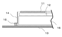
- FIG. 2 is a longitudinal sectional view of the power feeding device. Partial sectional view of a power feeding device for explaining the effect of the first embodiment
- the perspective view which shows the internal structure of the electric power feeder of Embodiment 2.
- the perspective view which shows the internal structure of the electric power feeder of Embodiment 3.
- the present invention is a coil unit used in a non-contact power feeding system including a power feeding device that generates a high-frequency electromagnetic field and a power receiving device that extracts power from the electromagnetic field.
- FIG. 1A and 1B are schematic diagrams of a non-contact power feeding system according to Embodiment 1 of the present invention.
- FIG. 1A shows a state viewed from the rear of the vehicle
- FIG. 1B shows a state viewed from the side of the vehicle. ing.
- the non-contact power feeding system includes, for example, a power feeding device 2 installed in a parking space, and a power receiving device 3 mounted on the bottom of an electric propulsion vehicle (hereinafter abbreviated as “vehicle”) 1, for example. Consists of When power is supplied from the power supply device 2 to the power reception device 3, the power supply device 2 and the power reception device 3 are arranged to face each other by appropriately moving the vehicle 1. A high-frequency electromagnetic field region 4 is formed between the power feeding device 2 and the power receiving device 3 that are arranged to face each other. The power receiving device 3 mounted on the vehicle extracts power from the high-frequency electromagnetic field region 4 and charges a rechargeable battery (not shown) with the extracted power.
- a rechargeable battery not shown
- the electromagnetic field region 4 there is a particularly strong electromagnetic field due to the power supply transmission from the power feeding device 2 to the power receiving device 3.
- FIG. 2 shows the internal structure of the power feeding device 2 shown in FIG. 1, and is a perspective view in particular with a cover (not shown) removed.
- FIG. 3 is a longitudinal sectional view of the power feeding device 2 of FIG.
- the power feeding device 2 is sequentially arranged on a magnetic shield plate 13 formed of a material having high magnetic permeability (low magnetic resistance) or low electric resistance (for example, metal).
- Base member 16 magnetic core portion 12, and primary coil 11 (power transmission coil).
- the magnetic shield 13 is installed on a surface (for example, the ground) substantially perpendicular to the magnetic flux generated at the winding center of the primary coil 11.
- an electromagnetic field restricting portion 14 that surrounds the base member 16, the magnetic core portion 12, and the primary coil 11 is fixed to the magnetic shielding plate 13 via the electrical connection portion 15.
- the base member 16 is made of a material other than a conductive material such as metal, for example, a resin containing a ceramic or a filler that improves thermal conductivity.
- a magnetic core 12 made of a high magnetic permeability material typified by ferrite and for concentrating the magnetic flux is disposed on the base member 16.
- the primary coil 11 is configured, for example, by winding a copper wire so as to have an annular shape. Note that the primary coil 11 in FIG. 2 is drawn in a disk shape.
- a substantially cylindrical electromagnetic field restricting part 14 made of a material having high magnetic permeability or low electric resistance (for example, metal) is disposed.
- the electromagnetic field regulating unit 14 is electrically connected to the magnetic shield plate 13 using, for example, screws or the like via electrical connection units 15 provided at a plurality of locations.
- the electromagnetic field restriction unit 14 surrounds the outer periphery of the power transmission coil 11 except for the upper side of the primary coil 11 in order to limit the region of the high frequency electromagnetic field generated by the primary coil 11.
- the power supply device 2 having the above-described configuration may be shallowly embedded in a parking space.
- the power feeding device 2 itself may be configured to be movable. Note that the power feeding device 2 is installed so that the magnetic shield 13 is located on the bottom side of the power feeding device 2 regardless of whether the power feeding device 2 is buried or movable.
- the power receiving device 3 similarly to the power feeding device 2, the power receiving device 3 also includes a magnetic shielding plate, a base member, a magnetic core portion, and a coil (secondary coil).
- a magnetic shield plate of the power receiving device 3 is attached to the vehicle 1.
- the secondary coil of the power receiving device 3 receives electric field generated by the primary coil 11 of the power feeding device 2 and generates electric power.
- the power receiving device 3 does not include an electromagnetic field restriction unit. Specifically, a member for regulating an electromagnetic field, which is formed of a material having high magnetic permeability or low electrical resistance, is not provided outside the outer periphery of the secondary coil of the power receiving device 3. Therefore, the radial direction of the secondary coil of the power receiving device 3 is magnetically opened. As a result, magnetic fluxes in various directions including the radial direction of the secondary coil can pass through the secondary coil of the power receiving device.
- the vehicle 1 is stopped so that the power receiving device 3 (see FIG. 1) and the power feeding device 2 face each other through the air gap. In this way, power is transmitted from the power supply device 2 to the power reception device 3 in a contactless manner with the power reception device 3 and the power supply device 2 positioned so as to face each other.
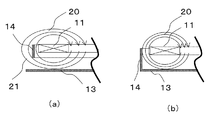
- FIG. 4 is a schematic partial cross-sectional view for explaining the relationship among the primary coil 11, the electromagnetic field restricting portion 14, and the magnetic shielding plate 13, and shows the same position as FIG. FIG. 4A shows a case (comparative example) where the electromagnetic field restricting portion 14 and the magnetic shield 13 are not electrically connected.
- FIG. 4B is a diagram suitable for explaining the technical effect of the first embodiment, and shows a case where the electromagnetic field restricting portion 14 and the magnetic shielding plate 13 are electrically connected.
- the magnetic flux 20 generated by the primary coil 11 is confined inside the electromagnetic field restriction unit 14.
- the electromagnetic field restriction unit 14 passes between the electromagnetic field restriction unit 14 and the magnetic shielding plate 13.
- the magnetic flux 21 which spreads outside and spreads greatly is generated. Further, since the magnetic flux 21 forms a magnetic path that circulates around the electromagnetic field restriction unit 14, the primary coil 11 and the electromagnetic field restriction unit 14 function like a transformer, and a current flows through the electromagnetic field restriction unit 14. As a result, the magnetic flux is lost, and the power supplied from the power feeding device 2 to the power receiving device 2 is lost.
- the magnetic flux 20 is in a direction other than the opening side direction of the electromagnetic field restriction unit 14 (primary coil). 11 (in the radial direction) is suppressed.
- the spread of the magnetic flux 20 in the direction between the radial direction of the primary coil 11 and the opening side direction of the electromagnetic field restriction unit 14 mainly varies depending on the positional relationship between the primary coil 11 and the electromagnetic field restriction unit 14.
- an eddy current is generated by the magnetic flux 20 in the electromagnetic field regulating unit 14 and the magnetic shield 13, and thus an eddy current loss (magnetic flux loss) is generated.
- the electromagnetic field restriction unit 14 and the magnetic shielding plate 13 are made of a low electrical resistance material such as aluminum, and / or a high permeability material such as ferrite is disposed in the vicinity of the primary coil 11, The magnetic flux 20 in the vicinity of the magnetic shield 13 is reduced. Thereby, magnetic flux loss can be reduced.
- the electromagnetic field restricting portion 14 arranged outside the outer periphery of the primary coil 11 is electrically connected to the magnetic shield plate 13, thereby expanding the radial direction of the primary coil 11 of the magnetic flux 20 generated by the primary coil 11.
- the electromagnetic field region 4 can be limited.
- the power can be transmitted efficiently even when the power feeding device 2 or the power receiving device 3 deviates from the facing position where the coils face each other.
- FIG. 5 is a perspective view of the internal structure of the power feeding apparatus according to the second embodiment, in which the height of the electromagnetic field restriction unit 14 is partially different.
- a power receiving device 3 (see FIG. 1) is mounted at a rear position at the bottom of the vehicle 1, a power feeding device 2 is installed at a position opposite to the power receiving device 3, and a structure that causes magnetic flux loss at the rear of the vehicle 1
- FIG. 5 shows a power supply device that addresses the case where it is installed.
- the portion of the electromagnetic field restriction portion 14 on the rear side of the power feeding device 2 that is, the side corresponding to the rear of the vehicle 1 is made higher than the other portions (on the side of the precaution plate 13). The distance from one end to the other is increased). Thereby, spreading of the magnetic flux 20 to the rear of the vehicle 1 can be suppressed, and loss of power supplied from the power feeding device 2 to the power receiving device 2 can be minimized.
- FIG. 6 is a perspective view of the internal structure of the power feeding apparatus according to the third embodiment in which the height of the electromagnetic field restriction unit 14 is partially zero.
- the magnetic flux 20 spreads in a specific direction by setting the arrangement position of the electromagnetic field restriction unit 14 with respect to the primary coil 11 based on the installation state of the power receiving device 3 (see FIG. 1) and the power feeding device 2. Can be suppressed. As a result, the loss of power supplied from the power feeding device 2 to the power receiving device 2 can be minimized.
- by partially setting the height of the electromagnetic field regulating unit 14 to zero it is possible to further suppress the magnetic flux loss caused by the generation of eddy current in the electromagnetic field regulating unit 14.
- the portion on the rear side of the electromagnetic field regulating portion 14 corresponding to the rear of the electric propulsion vehicle 1 is made higher than the other portions.
- portion of the electromagnetic field restricting portion 14 corresponding to the direction in which the magnetic flux loss is small may be made lower than the other portions so that the magnetic flux 20 spreads in the direction in which the magnetic flux loss is small. Thereby, supply electric power can be maximized.
- the non-contact power feeding system according to the present invention minimizes the loss of power supplied from the power feeding device to the power receiving device, and can maximize the power transmission efficiency even with respect to the positional deviation between the coil unit of the power feeding device and the power receiving device. It is useful for power feeding to the power receiving device of the electric propulsion vehicle 1.
Landscapes
- Engineering & Computer Science (AREA)
- Power Engineering (AREA)
- Computer Networks & Wireless Communication (AREA)
- Transportation (AREA)
- Mechanical Engineering (AREA)
- Physics & Mathematics (AREA)
- Electromagnetism (AREA)
- Electric Propulsion And Braking For Vehicles (AREA)
- Current-Collector Devices For Electrically Propelled Vehicles (AREA)
Abstract
給電装置2から受電装置3に電力を供給する非接触給電システムのコイルユニットにおいて、給電装置2の一次コイル11の外周の外側に、防磁板13と電気的に接続され、透磁率が高いまたは電気抵抗が低い材料によって形成された電磁場規制部14を配置し、一次コイル11によって発生する電磁場の分布領域を制限した。
Description
本発明は、例えば電気自動車またはハイブリッド車のような電気推進車両に搭載された二次コイルに、一次コイルから電力を非接触で供給する非接触給電システムに用いられるコイルユニットに関する。
安全性が高く、漏れ磁束が少なく、ノイズを減少することができる、出力トランスの1次コイルから2次コイルに電磁誘導で電力を伝達する給電装置が提案されている(例えば、特許文献1参照)。
このような給電装置は、一次コイルおよび二次コイルの対向面それぞれに設けられた絶縁部と、一次コイルおよび二次コイルそれぞれを、前記対向面を除いて覆う、磁気抵抗が低いあるいは電気抵抗が低い材料によって作成された外囲器とを有する。
しかしながら、一次コイルと二次コイルの両方に外囲器が存在するため、外囲器に渦電流が流れることを原因とする磁束損失が大きい。そのため、一次コイルから二次コイルに供給される電力が損失する。また、一次コイルの対向面と二次コイルの対向面とが対向し合う位置からいずれか一方のコイルがずれると、一次コイルによって発生した磁束が二次コイル側の外囲器によって二次コイルに到達できず、電力伝達効率が低下する。
本発明の目的は、従来技術の有するこのような問題点に鑑みてなされたものであり、磁束損失により生じる電力損失の最小化と、電力伝達効率を最大化とをすることができる非接触給電システムに用いられるコイルユニットを提供することである。
上記目的を達成するために、本発明は以下のように構成する。
本発明の態様によれば、給電装置から受電装置に電力を非接触で供給する非接触給電システムに用いられるコイルユニットであって、前記給電装置用として、電磁場を発生する一次コイルと、前記一次コイルの巻き中心に発生する磁束にほぼ垂直な面上に設置される、透磁率が高いまたは電気抵抗が低い材料によって形成された防磁板と、前記一次コイルの外周の外側に配置され、前記防磁板と電気的に接続され、透磁率が高いまたは電気抵抗が低い材料によって形成され、前記一次コイルによって発生する電磁場の分布領域を制限する電磁場規制部とを有し、前記受電装置用として、前記一次コイルが発生した電磁場の印加を受けて電力を発生する二次コイルを有することを特徴とする、コイルユニットが提供される。
本発明によれば、給電装置の電磁場規制部によって電磁場の分布領域が制限されているため、受電装置への電力伝達に寄与しない磁束の広がりを抑えることができ、非接触給電システムの電力伝達効率を向上できる。
また、電磁場規制部は、給電装置のみに配置されていることが好ましい。そのため、受電装置の電磁場規制部に渦電流が流れることを原因とする磁束損失がない。その結果、非接触給電システム全体の磁束損失を抑えることができる。
さらに、受電装置の二次コイルの外周の外側に透磁率が高いまたは電気抵抗が低い部材が存在しないため、二次コイルの径方向を含めて、様々の方向の磁束が受電装置の二次コイルを通過することができる。その結果、受電装置は、多くの電力を給電装置から受け取ることができる。受電装置の二次コイルを様々な方向の磁束が通過することができるので、給電装置または受電装置が互いのコイルが対向し合う対向位置からずれても、電力伝達効率を維持できる。
本発明のこれらの態様と特徴は、添付された図面についての好ましい実施の形態に関連した次の記述から明らかになる。この図面においては、
本発明の実施の形態1に係る非接触給電システムの概略図
実施の形態1の給電装置の内部構造を示す斜視図
図2の給電装置の縦断面図
実施の形態1の効果を説明するための給電装置の部分断面図
実施の形態2の給電装置の内部構造を示す斜視図
実施の形態3の給電装置の内部構造を示す斜視図
(実施の形態1)
本発明は、高周波の電磁場を発生させる給電装置と、電磁場から電力を取り出す受電装置とから構成された非接触給電システムに用いられるコイルユニットである。
本発明は、高周波の電磁場を発生させる給電装置と、電磁場から電力を取り出す受電装置とから構成された非接触給電システムに用いられるコイルユニットである。
以下、本発明の実施の形態について、図面を参照しながら説明する。なお、この実施の形態によって本発明が限定されるものではない。
図1は、本発明の実施の形態1に係る非接触給電システムの概略図で、図1(a)は車両後方から見た状態、図1(b)は車両側方から見た状態を示している。
図1に示されるように、非接触給電システムは、例えば駐車スペースに設置される給電装置2と、例えば電気推進車両(以下「車両」と略記する)1の底部に搭載される受電装置3とから構成される。給電装置2から受電装置3に給電するとき、車両1を適宜移動させることにより給電装置2と受電装置3が対向配置される。対向配置された給電装置2と受電装置3との間に、高周波の電磁場領域4が形成される。車両に搭載される受電装置3は、高周波の電磁場領域4から電力を取り出し、取り出した電力で充電池(図示せず)を充電する。
電磁場領域4には、給電装置2から受電装置3への電力供給伝達により、特に強い電磁場が存在する。
図2は、図1に示される給電装置2の内部構造を示しており、特にカバー(図示せず)を取り外した状態の斜視図である。また、図3は図2の給電装置2の縦断面図である。
図2乃至図3に示されるように、給電装置2は、透磁率が高い(磁気抵抗が低い)または電気抵抗が低い材料(例えば金属)によって形成された防磁板13上に順番に配置された、ベース部材16、磁心コア部12、および一次コイル11(送電用コイル)を有する。防磁板13は、一次コイル11の巻き中心に発生する磁束にほぼ垂直な面(例えば、地面)上に設置される。また、ベース部材16、磁心コア部12、および一次コイル11を囲う電磁場規制部14が、電気接続部15を介して防磁板13に固定されている。これらの部品は、カバー(図示せず)で覆われている。
ベース部材16は、金属などの導電性材料以外の材料、例えば、セラミック又は熱伝導率を向上させるフィラーを配合した樹脂から作製されている。
ベース部材16上に、フェライトに代表される高透磁率材料によって構成され、磁束を集中するための磁心コア部12が配置される。
一次コイル11は、環状の形状を有するように、例えば銅線が巻回されることにより構成されている。なお、図2の一次コイル11は、円盤状に省略して描かれている。
磁心コア部12および一次コイル11の外周の外側には、透磁率が高いまたは電気抵抗が低い材料(例えば金属)によって形成された略円筒形状の電磁場規制部14が配置されている。電磁場規制部14は、複数個所に設けられた電気接続部15を介して、例えばネジ等を使用して防磁板13に電気的に接続されている。電磁場規制部14は、一次コイル11によって発生した高周波の電磁場の領域を制限するために、一次コイル11の上方を除いて、送電コイル11の外周を囲んでいる。
以上のような構成を有する給電装置2は、駐車スペースに浅く埋設される場合がある。他にも、給電装置2自体が移動可能に構成される場合がある。なお、給電装置2は、埋設の場合であっても、移動可能な場合でもあっても、防磁板13が給電装置2の最も底側に位置するように設置される。
一方、受電装置3も、給電装置2と同様に、防磁板、ベース部材、磁心コア部、コイル(二次コイル)とを有する。受電装置3の防磁板は、車両1に取り付けられる。受電装置3の二次コイルは、給電装置2の一次コイル11が発生した電磁場の印加を受けて電力を発生する。なお、受電装置3は、給電装置2と異なり、電磁場規制部を備えていない。具体的には、受電装置3の二次コイルの外周の外側には、透磁率が高いまたは電気抵抗が低い材料から形成された、電磁場を規制する部材が設けられていない。そのため、受電装置3の二次コイルの径方向は、磁気的に開放されている。その結果、二次コイルの径方向を含めて、様々の方向の磁束が受電装置の二次コイルを通過することができる。
受電装置3(図1参照)と給電装置2とがエアギャップを介して対向するように、車両1が停止される。このように受電装置3と給電装置2とが対向するように位置決めされた状態で、給電装置2から受電装置3に電力が非接触で伝達される。
図4は、一次コイル11、電磁場規制部14、および防磁板13の関係を説明するための概略的な部分断面図であって、図3と同じ位置を示している。図4(a)は、電磁場規制部14と防磁板13が電気的に接続しない場合(比較例)を示している。比較例の場合、一次コイル11によって発生した磁束20の一部21が、電磁場規制部14と防磁板13の間を通過し、電磁場規制部14の外側を回り込む。図4(b)は、本実施の形態1の技術的効果の説明に適する図であり、電磁場規制部14と防磁板13とが電気的に接続されている場合を示している。本実施の形態1の場合、一次コイル11によって発生した磁束20は、電磁場規制部14の内側に閉じ込められる。
図4(a)に示す比較例のように電磁場規制部14と防磁板13とが電気的に接続されていない場合、電磁場規制部14と防磁板13との間を通過して電磁場規制部14の外側に回り込み、大きく広がる磁束21が生じる。また、この磁束21は電磁場規制部14を周回する磁路を形成するため、一次コイル11と電磁場規制部14とがトランスのように機能し、電磁場規制部14に電流が流れる。その結果、磁束が損失し、給電装置2から受電装置2への供給電力が損失する。
それに対して、図4(b)に示すように電磁場規制部14と防磁板13とが電気的に接続されている場合、磁束20は、電磁場規制部14の開口側方向以外の方向(一次コイル11の径方向)の広がりが抑止される。一次コイル11の径方向と電磁場規制部14開口側方向との間の方向への磁束20の広がりは、主に一次コイル11と電磁場規制部14の位置関係で変わる。
受電装置3(図1参照)と給電装置2とがエアギャップを介して対向するように位置決めされた状態で、給電装置2から受電装置3へと電力が非接触で伝達されると、電磁場規制部14が存在しない場合は磁束20が一次コイル11の径方向に広がる。その結果、例えば車両1の金属部などによって磁束損失が増え、受電装置3のコイルに到達する磁束が減少する。その結果、給電装置2から受電装置3への電力伝達効率が下がる。したがって、本実施の形態のように、電磁場規制部14によって磁束20の一次コイル11の径方向の広がりを抑止することにより、電力伝達効率を最大化できる。
なお、電磁場規制部14と防磁板13に磁束20によって渦電流が発生し、そのために渦電流損(磁束損失)が発生する。この対処として、電磁場規制部14と防磁板13をアルミニウムなどの低電気抵抗材料で構成する、および/または、一次コイル11の近傍にフェライトなどの高透磁率材料を配置して電磁場規制部14、防磁板13近傍の磁束20を少なくする。これにより、磁束損失を低減できる。
以上のように、一次コイル11の外周の外側に配置した電磁場規制部14を防磁板13に電気的に接続することにより、一次コイル11によって発生する磁束20の一次コイル11の径方向の広がりを抑制できる、すなわち、電磁場領域4を制限できる。
一次コイル11によって形成される電磁場領域4を制限することと、受電装置3の二次コイルの外周の外側に電磁場規制部14を配置しないこと(二次コイルの径方向が磁気的に開放される)により、給電装置2または受電装置3が互いのコイルが対向し合う対向位置からずれても、電力を効率よく伝達することが可能となる。
また、電磁場規制部14と防磁板13とを電気的に接続することにより、電磁場規制部14と防磁板13との間を磁束が通過することを原因とする供給電力の損失を抑えることができるとともに、磁束20の一次コイル11の径方向の広がりを抑制することができる。その結果、給電装置2から受電装置4へ非接触で伝達する電力を最大化することができる。
(実施の形態2)
図5は、電磁場規制部14の高さが部分的に異なる実施の形態2の給電装置の内部構造の斜視図を示す。車両1の底部の後方位置に受電装置3(図1参照)が搭載され、受電装置3の対向位置に給電装置2が設置され、車両1の後部に磁束損失を発生させる原因となる構造物が取り付けられている場合に対処する、給電装置を図5は示している。図5に示すように、給電装置2の後方側(すなわち車両1の後方に対応する側)の電磁場規制部14の部分は、他の部分に比べて高くされている(防滋板13側の一端から他端までの距離が大きくされている)。これにより、車両1の後方への磁束20の広がりを抑制することができ、給電装置2から受電装置2に供給する電力の損失を最小限に抑えることができる。
図5は、電磁場規制部14の高さが部分的に異なる実施の形態2の給電装置の内部構造の斜視図を示す。車両1の底部の後方位置に受電装置3(図1参照)が搭載され、受電装置3の対向位置に給電装置2が設置され、車両1の後部に磁束損失を発生させる原因となる構造物が取り付けられている場合に対処する、給電装置を図5は示している。図5に示すように、給電装置2の後方側(すなわち車両1の後方に対応する側)の電磁場規制部14の部分は、他の部分に比べて高くされている(防滋板13側の一端から他端までの距離が大きくされている)。これにより、車両1の後方への磁束20の広がりを抑制することができ、給電装置2から受電装置2に供給する電力の損失を最小限に抑えることができる。
(実施の形態3)
図6は、電磁場規制部14の高さが部分的にゼロである実施の形態3の給電装置の内部構造の斜視図を示す。図5と同様に、受電装置3(図1参照)と給電装置2の設置状態に基づいて一次コイル11に対する電磁場規制部14の配置位置を設定することにより、特定の方向への磁束20の広がりを抑制することができる。その結果、給電装置2から受電装置2への供給電力の損失を最小限に抑えることができる。さらに、電磁場規制部14の高さを部分的にゼロにすることにより、電磁場規制部14に渦電流が生じることを原因とする磁束損失をさらに抑制することができる。なお、実施の形態3においても、実施の形態2と同様に、は、電気推進車両1の後方に対応する電磁場規制部14の後方側の部分を他の部分に比べて高くすることが好ましい。
図6は、電磁場規制部14の高さが部分的にゼロである実施の形態3の給電装置の内部構造の斜視図を示す。図5と同様に、受電装置3(図1参照)と給電装置2の設置状態に基づいて一次コイル11に対する電磁場規制部14の配置位置を設定することにより、特定の方向への磁束20の広がりを抑制することができる。その結果、給電装置2から受電装置2への供給電力の損失を最小限に抑えることができる。さらに、電磁場規制部14の高さを部分的にゼロにすることにより、電磁場規制部14に渦電流が生じることを原因とする磁束損失をさらに抑制することができる。なお、実施の形態3においても、実施の形態2と同様に、は、電気推進車両1の後方に対応する電磁場規制部14の後方側の部分を他の部分に比べて高くすることが好ましい。
なお、磁束の損失が少ない方向に磁束20が広がるように、磁束の損失が少ない方向に対応する電磁場規制部14の部分を、他の部分に比べて低くしてもよい。これにより、供給電力を最大化することができる。
本発明は、添付図面を参照しながら好ましい実施の形態に関連して充分に記載されているが、この技術の熟練した人々にとっては種々の変形や修正は明白である。そのような変形や修正は、添付した請求の範囲による本発明の範囲から外れない限りにおいて、その中に含まれると理解されるべきである。
2011年1月24日に出願された日本特許出願第2011-011664号の明細書、図面、及び特許請求の範囲の開示内容は、全体として参照されて本明細書の中に取り入れられるものである。
本発明に係る非接触給電システムは、給電装置から受電装置に供給される電力の損失を最小にし、且つ給電装置と受電装置のコイルユニットの位置ずれに対しても電力伝達効率を最大化できるので、電気推進車両1の受電装置への給電等に有用である。
1 電気推進車両、 2 給電装置、 3 受電装置、 4 電磁場領域、
11 一次コイル、 12 磁心コア部、 13 防磁板、
14 電磁場規制部、 15 電気接続部、 20 磁束
11 一次コイル、 12 磁心コア部、 13 防磁板、
14 電磁場規制部、 15 電気接続部、 20 磁束
Claims (4)
- 給電装置から受電装置に電力を非接触で供給する非接触給電システムに用いられるコイルユニットであって、
前記給電装置用として、
電磁場を発生する一次コイルと、
前記一次コイルの巻き中心に発生する磁束にほぼ垂直な面上に設置される、透磁率が高いまたは電気抵抗が低い材料によって形成された防磁板と、
前記一次コイルの外周の外側に配置され、前記防磁板と電気的に接続され、透磁率が高いまたは電気抵抗が低い材料によって形成され、前記一次コイルによって発生する電磁場の分布領域を制限する電磁場規制部とを有し、
前記受電装置用として、
前記一次コイルが発生した電磁場の印加を受けて電力を発生する二次コイルを有することを特徴とする、コイルユニット。 - 前記二次コイルは、その径方向が磁気的に開放されている、請求項1に記載のコイルユニット。
- 前記電磁場規制部が前記一次コイルの外周を囲う略円筒形状である、請求項1または2に記載のコイルユニット。
- 前記円筒形状の電磁場規制部の前記防磁板側の一端から他端までの距離が不均一である、請求項3に記載のコイルユニット。
Applications Claiming Priority (2)
| Application Number | Priority Date | Filing Date | Title |
|---|---|---|---|
| JP2011011664A JP2014063768A (ja) | 2011-01-24 | 2011-01-24 | 非接触給電システムに用いられるコイルユニット |
| JP2011-011664 | 2011-01-24 |
Publications (1)
| Publication Number | Publication Date |
|---|---|
| WO2012102008A1 true WO2012102008A1 (ja) | 2012-08-02 |
Family
ID=46580584
Family Applications (1)
| Application Number | Title | Priority Date | Filing Date |
|---|---|---|---|
| PCT/JP2012/000389 Ceased WO2012102008A1 (ja) | 2011-01-24 | 2012-01-23 | 非接触給電システムに用いられるコイルユニット |
Country Status (2)
| Country | Link |
|---|---|
| JP (1) | JP2014063768A (ja) |
| WO (1) | WO2012102008A1 (ja) |
Cited By (3)
| Publication number | Priority date | Publication date | Assignee | Title |
|---|---|---|---|---|
| WO2014122121A1 (de) * | 2013-02-05 | 2014-08-14 | Conductix-Wampfler Gmbh | Spuleneinheit und vorrichtung zur induktiven übertragung elektrischer energie |
| WO2016040338A1 (en) * | 2014-09-09 | 2016-03-17 | Qualcomm Incorporated | System and method for reducing leakage flux in wireless electric vehicle charging systems |
| US9923406B2 (en) | 2015-09-04 | 2018-03-20 | Qualcomm Incorporated | System and method for reducing leakage flux in wireless charging systems |
Families Citing this family (1)
| Publication number | Priority date | Publication date | Assignee | Title |
|---|---|---|---|---|
| DE102018103854A1 (de) | 2018-02-21 | 2019-08-22 | Dr. Ing. H.C. F. Porsche Aktiengesellschaft | Ladeeinrichtung |
Citations (5)
| Publication number | Priority date | Publication date | Assignee | Title |
|---|---|---|---|---|
| JP2009060067A (ja) * | 2007-08-31 | 2009-03-19 | Laird Technologies Inc | 電磁干渉シールド及びその製造方法 |
| WO2010041321A1 (ja) * | 2008-10-09 | 2010-04-15 | トヨタ自動車株式会社 | 非接触電力伝達装置および非接触電力伝達装置を備える車両 |
| WO2010103639A1 (ja) * | 2009-03-12 | 2010-09-16 | トヨタ自動車株式会社 | 電動車両 |
| WO2010106648A1 (ja) * | 2009-03-18 | 2010-09-23 | トヨタ自動車株式会社 | 非接触受電装置、非接触送電装置、非接触給電システムおよび車両 |
| JP2012016250A (ja) * | 2010-07-05 | 2012-01-19 | Panasonic Electric Works Co Ltd | 非接触給電機能付き什器 |
-
2011
- 2011-01-24 JP JP2011011664A patent/JP2014063768A/ja active Pending
-
2012
- 2012-01-23 WO PCT/JP2012/000389 patent/WO2012102008A1/ja not_active Ceased
Patent Citations (5)
| Publication number | Priority date | Publication date | Assignee | Title |
|---|---|---|---|---|
| JP2009060067A (ja) * | 2007-08-31 | 2009-03-19 | Laird Technologies Inc | 電磁干渉シールド及びその製造方法 |
| WO2010041321A1 (ja) * | 2008-10-09 | 2010-04-15 | トヨタ自動車株式会社 | 非接触電力伝達装置および非接触電力伝達装置を備える車両 |
| WO2010103639A1 (ja) * | 2009-03-12 | 2010-09-16 | トヨタ自動車株式会社 | 電動車両 |
| WO2010106648A1 (ja) * | 2009-03-18 | 2010-09-23 | トヨタ自動車株式会社 | 非接触受電装置、非接触送電装置、非接触給電システムおよび車両 |
| JP2012016250A (ja) * | 2010-07-05 | 2012-01-19 | Panasonic Electric Works Co Ltd | 非接触給電機能付き什器 |
Cited By (5)
| Publication number | Priority date | Publication date | Assignee | Title |
|---|---|---|---|---|
| WO2014122121A1 (de) * | 2013-02-05 | 2014-08-14 | Conductix-Wampfler Gmbh | Spuleneinheit und vorrichtung zur induktiven übertragung elektrischer energie |
| CN104969315A (zh) * | 2013-02-05 | 2015-10-07 | 康达提斯-瓦普弗勒有限公司 | 用于感应式传输电能的线圈单元和装置 |
| WO2016040338A1 (en) * | 2014-09-09 | 2016-03-17 | Qualcomm Incorporated | System and method for reducing leakage flux in wireless electric vehicle charging systems |
| US9889754B2 (en) | 2014-09-09 | 2018-02-13 | Qualcomm Incorporated | System and method for reducing leakage flux in wireless electric vehicle charging systems |
| US9923406B2 (en) | 2015-09-04 | 2018-03-20 | Qualcomm Incorporated | System and method for reducing leakage flux in wireless charging systems |
Also Published As
| Publication number | Publication date |
|---|---|
| JP2014063768A (ja) | 2014-04-10 |
Similar Documents
| Publication | Publication Date | Title |
|---|---|---|
| US11264834B2 (en) | Coil apparatus | |
| JP5921839B2 (ja) | 非接触給電トランス | |
| JP6475684B2 (ja) | コイルユニット | |
| US11328852B2 (en) | Coil device | |
| JP6520567B2 (ja) | 給電装置 | |
| JP6179375B2 (ja) | コイルユニット | |
| JP6370558B2 (ja) | コイルユニット及びそれを有する給電システム | |
| JP6665454B2 (ja) | コイル装置及びコイルシステム | |
| JP5717090B2 (ja) | 受電ユニット、該受電ユニットを備えた充電システム及び電気機器 | |
| US20160233723A1 (en) | Enclosures for high power wireless power transfer systems | |
| JPWO2012039077A1 (ja) | 非接触給電装置 | |
| JP2012228150A (ja) | 共鳴式非接触給電システム、共鳴式非接触給電システムの送電側装置及び車載充電装置 | |
| WO2012090342A1 (ja) | 非接触給電システムに用いられるコイルユニット | |
| JP2015008547A (ja) | 非接触充電装置 | |
| JP2014053366A (ja) | コイル装置 | |
| JP6111645B2 (ja) | コイル装置及びそれを用いたワイヤレス電力伝送システム | |
| US9647535B2 (en) | Compact structure of power-supply apparatus capable of minimizing electromagnetic noise | |
| EP2953148B1 (en) | Contactless-power-transfer-device coil and contactless power-transfer device | |
| WO2014156014A1 (ja) | 非接触充電装置 | |
| JP2014063768A (ja) | 非接触給電システムに用いられるコイルユニット | |
| JP2015090912A (ja) | リアクトル | |
| JP6454941B2 (ja) | 非接触給電装置および非接触給電システム | |
| CN106463252B (zh) | 线圈装置 | |
| JP6301675B2 (ja) | コイルユニット及びそれを有する給電システム | |
| JP2014043114A (ja) | 非接触給電システムに用いられるコイルユニット |
Legal Events
| Date | Code | Title | Description |
|---|---|---|---|
| 121 | Ep: the epo has been informed by wipo that ep was designated in this application |
Ref document number: 12739987 Country of ref document: EP Kind code of ref document: A1 |
|
| NENP | Non-entry into the national phase |
Ref country code: DE |
|
| 122 | Ep: pct application non-entry in european phase |
Ref document number: 12739987 Country of ref document: EP Kind code of ref document: A1 |
|
| NENP | Non-entry into the national phase |
Ref country code: JP |