WO2012102016A1 - 磁気冷凍システムおよび自動車用空調装置 - Google Patents
磁気冷凍システムおよび自動車用空調装置 Download PDFInfo
- Publication number
- WO2012102016A1 WO2012102016A1 PCT/JP2012/000412 JP2012000412W WO2012102016A1 WO 2012102016 A1 WO2012102016 A1 WO 2012102016A1 JP 2012000412 W JP2012000412 W JP 2012000412W WO 2012102016 A1 WO2012102016 A1 WO 2012102016A1
- Authority
- WO
- WIPO (PCT)
- Prior art keywords
- refrigerant
- outlet
- magnetic
- heat exchanger
- magnetic field
- Prior art date
- Legal status (The legal status is an assumption and is not a legal conclusion. Google has not performed a legal analysis and makes no representation as to the accuracy of the status listed.)
- Ceased
Links
Images


Classifications
-
- F—MECHANICAL ENGINEERING; LIGHTING; HEATING; WEAPONS; BLASTING
- F25—REFRIGERATION OR COOLING; COMBINED HEATING AND REFRIGERATION SYSTEMS; HEAT PUMP SYSTEMS; MANUFACTURE OR STORAGE OF ICE; LIQUEFACTION SOLIDIFICATION OF GASES
- F25B—REFRIGERATION MACHINES, PLANTS OR SYSTEMS; COMBINED HEATING AND REFRIGERATION SYSTEMS; HEAT PUMP SYSTEMS
- F25B21/00—Machines, plants or systems, using electric or magnetic effects
-
- B—PERFORMING OPERATIONS; TRANSPORTING
- B60—VEHICLES IN GENERAL
- B60H—ARRANGEMENTS OF HEATING, COOLING, VENTILATING OR OTHER AIR-TREATING DEVICES SPECIALLY ADAPTED FOR PASSENGER OR GOODS SPACES OF VEHICLES
- B60H1/00—Heating, cooling or ventilating devices
- B60H1/00642—Control systems or circuits; Control members or indication devices for heating, cooling or ventilating devices
- B60H1/00814—Control systems or circuits characterised by their output, for controlling particular components of the heating, cooling or ventilating installation
- B60H1/00821—Control systems or circuits characterised by their output, for controlling particular components of the heating, cooling or ventilating installation the components being ventilating, air admitting or air distributing devices
- B60H1/00864—Ventilators and damper doors
-
- B—PERFORMING OPERATIONS; TRANSPORTING
- B60—VEHICLES IN GENERAL
- B60H—ARRANGEMENTS OF HEATING, COOLING, VENTILATING OR OTHER AIR-TREATING DEVICES SPECIALLY ADAPTED FOR PASSENGER OR GOODS SPACES OF VEHICLES
- B60H1/00—Heating, cooling or ventilating devices
- B60H1/00642—Control systems or circuits; Control members or indication devices for heating, cooling or ventilating devices
- B60H1/00814—Control systems or circuits characterised by their output, for controlling particular components of the heating, cooling or ventilating installation
- B60H1/00878—Control systems or circuits characterised by their output, for controlling particular components of the heating, cooling or ventilating installation the components being temperature regulating devices
- B60H1/00885—Controlling the flow of heating or cooling liquid, e.g. valves or pumps
-
- B—PERFORMING OPERATIONS; TRANSPORTING
- B60—VEHICLES IN GENERAL
- B60H—ARRANGEMENTS OF HEATING, COOLING, VENTILATING OR OTHER AIR-TREATING DEVICES SPECIALLY ADAPTED FOR PASSENGER OR GOODS SPACES OF VEHICLES
- B60H1/00—Heating, cooling or ventilating devices
- B60H1/32—Cooling devices
-
- F—MECHANICAL ENGINEERING; LIGHTING; HEATING; WEAPONS; BLASTING
- F25—REFRIGERATION OR COOLING; COMBINED HEATING AND REFRIGERATION SYSTEMS; HEAT PUMP SYSTEMS; MANUFACTURE OR STORAGE OF ICE; LIQUEFACTION SOLIDIFICATION OF GASES
- F25B—REFRIGERATION MACHINES, PLANTS OR SYSTEMS; COMBINED HEATING AND REFRIGERATION SYSTEMS; HEAT PUMP SYSTEMS
- F25B2321/00—Details of machines, plants or systems, using electric or magnetic effects
- F25B2321/002—Details of machines, plants or systems, using electric or magnetic effects by using magneto-caloric effects
- F25B2321/0022—Details of machines, plants or systems, using electric or magnetic effects by using magneto-caloric effects with a rotating or otherwise moving magnet
-
- Y—GENERAL TAGGING OF NEW TECHNOLOGICAL DEVELOPMENTS; GENERAL TAGGING OF CROSS-SECTIONAL TECHNOLOGIES SPANNING OVER SEVERAL SECTIONS OF THE IPC; TECHNICAL SUBJECTS COVERED BY FORMER USPC CROSS-REFERENCE ART COLLECTIONS [XRACs] AND DIGESTS
- Y02—TECHNOLOGIES OR APPLICATIONS FOR MITIGATION OR ADAPTATION AGAINST CLIMATE CHANGE
- Y02B—CLIMATE CHANGE MITIGATION TECHNOLOGIES RELATED TO BUILDINGS, e.g. HOUSING, HOUSE APPLIANCES OR RELATED END-USER APPLICATIONS
- Y02B30/00—Energy efficient heating, ventilation or air conditioning [HVAC]
Definitions
- This disclosure relates to a magnetic refrigeration system and an air conditioner for an automobile to which the magnetic refrigeration system is applied.
- the magnetic refrigeration system disclosed in Patent Document 1 includes a magnetic working substance mounted on a railway vehicle, a strong magnetic field generator that applies a magnetic field to the magnetic working substance, and a magnetic work that rises when the magnetic field from the strong magnetic field generator increases.
- a second heat exchange channel that circulates, a pump, a heat exchanger, and the like disposed in each heat exchange channel are configured.
- the pump provided in the 1st heat exchange flow path is operated, and the heat carrier heated up with the heat of magnetic work substance is made into the outdoor air with a heat exchanger.
- the pump provided in the second heat exchange flow path is operated, and the heat medium cooled by the cold heat of the magnetic working material is removed by the heat exchanger. Heat is exchanged with the passenger compartment air.
- the strong magnetic field generator is comprised by the superconducting coil etc.
- the use is restricted to a special thing, and it is for automobiles. It is difficult to apply to general-purpose products such as air conditioners.
- the refrigerant (magnetic heat transport medium) is moved to one end side (high temperature end side) of the magnetic working material and applied to the magnetic working material.
- An AMR (Active Magnetic Refrigerator) system that stores the cold and warm heat generated by the magnetocaloric effect in the magnetic working material itself by moving the refrigerant to the other end side (low temperature end side) of the magnetic working material after reducing the magnetic field A magnetic refrigeration system is known.
- an AMR type magnetic refrigeration system has a container in which a magnetic working material is filled and a refrigerant flow path through which a refrigerant flows is formed. According to application / removal of a magnetic field to the magnetic working material, The refrigerant is configured to reciprocate between one end side and the other end side of the container.
- COP represents the cooling / heating capacity per 1 kW of power consumption.
- This disclosure is intended to provide a magnetic refrigeration system and an automotive air conditioner to which the magnetic refrigeration system is applied.
- a magnetic refrigeration system includes a cylindrical container in which a plurality of working chambers in which a magnetic working material having a magnetocaloric effect is arranged and in which a refrigerant flows are radially formed in a circumferential direction; Among the pair of refrigerant inlets / outlets provided on both end surfaces of the container in the longitudinal direction, the refrigerant flowing out from the refrigerant discharge part of one refrigerant inlet / outlet is the first heat exchange.
- the first refrigerant circulation circuit configured to return to the refrigerant suction portion of one refrigerant inlet / outlet through the chamber, and the refrigerant flowing out of the refrigerant discharge portion of the other refrigerant inlet / outlet of the pair of inlets / outlets is the second heat exchanger
- a second refrigerant circulation circuit configured to pass through and return to the refrigerant inlet of the other refrigerant inlet / outlet, and a refrigerant moving unit that moves the refrigerant between one refrigerant inlet / outlet side and the other refrigerant inlet / outlet side, Preparation
- the refrigerant moving unit moves the refrigerant from the other refrigerant inlet / outlet side to one refrigerant inlet / outlet side after the magnetic field is applied to the magnetic working material by the magnetic field application / removal unit, and the magnetic field application / removal unit removes the magnetic field from the magnetic working material. Then, the refrigerant is moved from one ref
- the temperature of the magnetic working material is increased by moving the refrigerant from the other refrigerant inlet / outlet side to the one refrigerant inlet / outlet side in the working chamber.
- the refrigerant in the vicinity of the one refrigerant inlet / outlet can be caused to flow into the first heat exchanger via the first refrigerant circulation circuit.
- the other coolant is cooled by the cold heat of the magnetic working material generated by removing the magnetic field by moving the refrigerant from one refrigerant inlet / outlet side to the other refrigerant inlet / outlet side in the working chamber.
- the refrigerant in the vicinity of the refrigerant inlet / outlet can be caused to flow into the second heat exchanger via the second refrigerant circulation circuit.
- the refrigerant heated by the heat generated in the magnetic working material can be directly flowed into the first heat exchanger, and the refrigerant cooled by the cold generated in the magnetic working material can be directly flowed into the second heat exchanger. Further, it is possible to reduce heat exchange loss when transporting hot and cold heat generated in the magnetic working substance, and to improve the COP of the magnetic refrigeration system.
- the refrigerant that has passed through the second heat exchanger works from the second refrigerant circulation circuit via the other refrigerant inlet / outlet. Will flow into the chamber.
- the refrigerant that has passed through the first heat exchanger works from the first refrigerant circulation circuit through the one refrigerant inlet / outlet. Will flow into the chamber.
- the volume of the space constituting the refrigerant suction part and the refrigerant discharge part is made smaller than the refrigerant discharge volume per one time in the refrigerant moving part, so that the temperature of the refrigerant is increased by the heat generated in the magnetic work substance, and the magnetic It can suppress that the refrigerant
- the refrigerant suction part is provided with a suction valve that is opened when the refrigerant is sucked into the work chamber, and the refrigerant discharge part is provided with a discharge valve that is opened when the refrigerant is discharged from the work chamber. Yes.
- the refrigerant in the vicinity of one refrigerant inlet / outlet heated by the heat of the magnetic working substance generated by the application of the magnetic field is surely passed through the first refrigerant circulation circuit.
- the refrigerant flowing out of the second heat exchanger can be sucked into the working chamber from the other refrigerant inlet / outlet.
- the refrigerant near the other refrigerant inlet / outlet cooled by the cold heat of the magnetic working material generated by the removal of the magnetic field is surely passed through the second refrigerant circulation circuit to the second heat exchanger.
- the refrigerant flowing out from the first heat exchanger can be sucked into the working chamber from one refrigerant inlet / outlet.
- the discharge valve is arranged closer to the working chamber than the suction valve in the longitudinal direction of the container.
- the suction valve is disposed adjacent to the work chamber and has a communication plate formed with a communication hole communicating with the work chamber, and a communication hole that rotates in the circumferential direction of the container. It is comprised with the rotary valve which has a rotating disk which opens and closes.
- stagnation of the refrigerant around the suction valve can be suppressed, and unnecessary heat exchange between the refrigerant staying around the suction valve and the refrigerant discharged from the work chamber via the discharge valve can be suppressed. Is possible. Thereby, the heat exchange loss at the time of transporting the warm and cold generated in the magnetic working substance can be reduced, and the COP of the magnetic refrigeration system can be improved.
- the magnetic refrigeration system can be realized with a simple configuration.
- the refrigerant is in one direction in the order of the refrigerant discharge part, the refrigerant inlet in the first heat exchanger, the refrigerant outlet in the first heat exchanger, and the refrigerant inlet in the refrigerant inlet and outlet of the one refrigerant inlet / outlet.
- a first backflow prevention unit that allows the refrigerant to flow into the refrigerant inlet and the refrigerant outlet at the other refrigerant inlet / outlet, the refrigerant outlet, the refrigerant inlet at the second heat exchanger, and the second heat exchanger
- a second backflow prevention unit that allows the refrigerant to flow in one direction in the order of the refrigerant outlet and the refrigerant suction unit is provided.
- the refrigerant in the vicinity of one refrigerant inlet / outlet heated by the heat of the magnetic working material generated by the application of the magnetic field is surely passed through the first refrigerant circulation circuit.
- the refrigerant flowing out of the second heat exchanger can be sucked into the working chamber from the other refrigerant inlet / outlet.
- the refrigerant near the other refrigerant inlet / outlet cooled by the cold heat of the magnetic working material generated by the removal of the magnetic field is surely passed through the second refrigerant circulation circuit to the second heat exchanger.
- the refrigerant flowing out from the first heat exchanger can be sucked into the working chamber from one refrigerant inlet / outlet.
- At least one of the first backflow prevention unit and the second backflow prevention unit is configured by a fluid diode having a resistance smaller in the forward direction of the refrigerant flow than in the reverse direction of the refrigerant flow, thereby simplifying the magnetic refrigeration system. Can be realized.
- the refrigerant suction part is provided so as to be positioned on the same circumference when viewed from the longitudinal direction of the container.
- the part is preferably provided so as to be positioned on the same circumference when viewed from the longitudinal direction of the container.
- the magnetic field application / removal unit includes a magnetic field generation unit that generates a magnetic field, a rotation shaft that rotatably supports the magnetic field generation unit, and a drive unit that drives the rotation axis.
- a magnetic field generation unit that generates a magnetic field
- a rotation shaft that rotatably supports the magnetic field generation unit
- a drive unit that drives the rotation axis.
- a power transmission mechanism that transmits power from the driving unit to the refrigerant moving unit is provided, and the refrigerant moving unit is configured to generate a refrigerant between the one refrigerant inlet / outlet and the other refrigerant inlet / outlet by the power transmitted through the power transmission mechanism. Is moved back and forth.
- the refrigerant moving unit is driven by the power of the driving unit of the magnetic field application removing unit, the driving source of the refrigerant moving unit and the magnetic field application removing unit can be shared, so the magnetic refrigeration system can be This can be realized with a simple configuration. As a result, it is possible to further increase the COP of the magnetic refrigeration system by suppressing an increase in power consumption in the magnetic refrigeration system.
- the refrigerant moving unit is constituted by a multi-cylinder type piston pump having a plurality of cylinders corresponding to a plurality of work chambers and a plurality of pistons.
- a case that forms an air flow path for the blown air to be blown into the passenger compartment is provided, and the blown air to be blown into the passenger compartment is heated by the first heat exchanger. It is possible to cool and heat the vehicle interior by configuring a heat exchanger for heating and a cooling heat exchanger that cools the air blown into the vehicle interior by the second heat exchanger Become.
- the first heat exchanger is arranged on the downstream side of the air flow of the blown air from the second heat exchanger in the case, the blown air that has been cooled and dehumidified by the second heat exchanger.
- the blown air can be dehumidified during heating of the passenger compartment.
- a configuration may be provided that includes a temperature adjusting unit that adjusts the air volume of the blown air flowing into the first heat exchanger to adjust the temperature of the air blown into the vehicle interior.
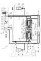
- FIG. 1 is an overall configuration diagram of an automotive air conditioner according to a first embodiment. It is an enlarged view of the magnetic refrigerator concerning a 1st embodiment.
- FIG. 3 is a cross-sectional view taken along line AA in FIG. 2. It is explanatory drawing explaining the principle of operation of the magnetic refrigerator which concerns on 1st Embodiment.
- It is a whole lineblock diagram showing the refrigerant circuit at the time of air conditioning mode of the air-conditioner for vehicles concerning a 1st embodiment.
- It is a whole block diagram which shows the refrigerant circuit at the time of the heating mode of the motor vehicle air conditioner which concerns on 1st Embodiment.
- FIG. 20 is a DD sectional view of FIG. 19.
- FIG. 20 is a cross-sectional view taken along line EE of FIG. It is a typical sectional view of a nozzle type fluidic diode concerning an 11th embodiment. It is explanatory drawing explaining the spiral type fluidic diode which concerns on 11th Embodiment.
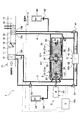
- FIG. 1 is an overall configuration diagram of an automotive air conditioner 1 according to the present embodiment.
- the magnetic refrigeration system 2 of the present disclosure is applied to an automotive air conditioner 1 that performs air conditioning in the interior of a vehicle.
- the air conditioner 1 for an automobile is an air conditioner that is mounted on an automobile that obtains a driving force for running a vehicle from an internal combustion engine (engine).
- the automotive air conditioner 1 includes a magnetic refrigeration system 2 disposed in the engine room, an indoor air conditioning unit 10 disposed in the vehicle compartment, and an air conditioning control device 100.
- the magnetic refrigeration system 2 of the present embodiment is configured to be able to switch between a cooling mode for cooling the passenger compartment, a heating mode for heating the passenger compartment, and a dehumidifying mode refrigerant circuit for dehumidifying when heating the passenger compartment.
- the air conditioner 1 can perform cooling, heating, and dehumidification of the passenger compartment.
- the magnetic refrigeration system 2 employs an AMR method in which cold and warm heat generated by the magnetocaloric effect is stored in the magnetic working material 30 itself.
- the magnetic refrigeration system 2 of the present embodiment includes a magnetic refrigerator 3 that generates cold and warm heat by a magnetocaloric effect, and a heat exchanger (first heat exchanger) that heats the refrigerant that has been heated by the heat generated by the magnetic refrigerator 3.
- a high temperature side refrigerant circuit (first refrigerant circulation circuit) 4 circulated to 13 and a low temperature side refrigerant that circulates the refrigerant cooled by the cold generated in the magnetic refrigerator 3 to the cooling heat exchanger (second heat exchanger) 12.
- a circuit (second refrigerant circulation circuit) 5 is provided.
- the magnetic refrigerator 3 includes a heat exchange container 31 in which a working chamber 311 is formed in which a magnetic working material 30 having a magnetocaloric effect is accommodated and a refrigerant (for example, water or antifreeze) serving as a heat transport medium flows.
- a magnetic field application / removal device 32 for applying / removing a magnetic field to / from the magnetic work substance, a refrigerant pump 34 for moving the refrigerant in the heat exchange vessel 31, an electric motor 35 as a drive source of the magnetic refrigerator 3, and the like. has been.
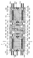
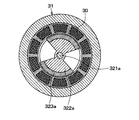
- FIG. 2 is an enlarged view of the magnetic refrigerator 3
- FIG. 3 is a cross-sectional view taken along the line AA in FIG.
- FIG. 2 shows an axial section of the magnetic refrigerator 3.
- the heat exchange container 31 of the present embodiment is divided into a high temperature side container 31a for generating heat by the magnetocaloric effect and a low temperature side container 31b for generating cold by the magnetocaloric effect. Yes.
- the high temperature side container 31 a and the low temperature side container 31 b are arranged side by side in the coaxial direction via the refrigerant pump 34.
- the high temperature side container 31a and the low temperature side container 31b are formed of cylindrical containers.
- Each container 31a, 31b is formed with a work chamber 311 in which a magnetic working material 30 is accommodated in a wall portion constituting an outer shell and a refrigerant flows.
- each container 31a, 31b is formed with a plurality of working chambers 311 radially in the circumferential direction.
- a pair of refrigerant inlets and outlets 312 and 313 are formed on the end surfaces of both ends of the heat exchange container 31 (opposite sides of the refrigerant pumps 34 in the respective containers 31a and 31b), and through the pair of refrigerant inlets and outlets 312 and 313, The refrigerant can be sucked and discharged.
- communication passages 314 and 315 communicating with each other in a cylinder bore 344 of the refrigerant pump 34 described later are formed on the end faces of the respective containers 31a and 31b on the refrigerant pump 34 side. Note that a plurality of the communication paths 314 and 315 are formed corresponding to the high temperature side entrances 312 and the low temperature side entrances 313.
- the high temperature side inlet / outlet 312 formed in the high temperature side container 31a is provided corresponding to each work chamber 311 of the high temperature side container 31a and communicates with the corresponding work chamber 311. ing.
- Each high temperature side entrance / exit 312 includes a refrigerant suction part 312a for sucking a refrigerant and a refrigerant discharge part 312b for discharging the refrigerant.
- the refrigerant suction part 312a is provided with a suction valve (suction valve) 312c that is opened when the refrigerant is sucked, and a discharge valve (discharge valve) 312d that is opened when the refrigerant is discharged to the refrigerant discharge part 312b.
- the suction valve 312c and the discharge valve 312d of the present embodiment are constituted by reed valves that are configured by fixing one end of a plate material having elasticity.
- the low temperature side inlet / outlet 313 formed in the low temperature side container 31b is provided corresponding to each work chamber 311 of the low temperature side container 31b. Communicate.
- Each low temperature side inlet / outlet 313 has a refrigerant suction part 313a and a refrigerant discharge part 313b, similarly to the high temperature side inlet / outlet 312, a suction valve 313c is provided in the refrigerant suction part 313a, and a discharge valve 313d is provided in the refrigerant discharge part 313b. It has been.
- communication passages 314 and 315 communicating with each other in a cylinder bore 344 of the refrigerant pump 34 described later are formed on the end faces of the respective containers 31a and 31b on the refrigerant pump 34 side. Note that a plurality of the communication paths 314 and 315 are formed corresponding to the high temperature side entrances 312 and the low temperature side entrances 313.
- the rotary shafts 321a and 321b are rotatably supported by support members 36a and 36b provided at both ends in the longitudinal direction of the containers 31a and 31b.
- the high temperature side rotating shaft 321a accommodated in the high temperature side container 31a has the edge part by the side of the refrigerant
- the low temperature side rotating shaft 321b accommodated in the low temperature side container 31b has an end on the refrigerant pump 34 side extending outside the low temperature side container 31b, and will be described later on a drive shaft 341 of the refrigerant pump 34 described later. It is connected via a speed change mechanism 37b. Furthermore, the end of the low temperature side rotating shaft 321b opposite to the refrigerant pump 34 extends to the outside of the low temperature side container 31b, and an electric motor 35 (described later) that rotates the rotating shafts 321a and 321b is connected thereto. .
- the rotors 322a and 322b are arranged on the rotating shafts 321a and 321b so as to rotate with a predetermined gap with respect to the inner peripheral surfaces of the containers 31a and 31b with the permanent magnets 323a and 323b provided on the outer peripheral surfaces. It is fixed.
- the permanent magnets 323a and 323b are periodically provided to the upper work chamber 311 and the lower work chamber 311 in the containers 31a and 31b in accordance with the rotation of the rotation shafts 321a and 321b. Is provided on the outer peripheral surface of the rotors 322a and 322b (for example, in a range of about 1/4).
- the magnetic field generated around the permanent magnets 323a and 323b according to the rotation of the rotating shafts 321a and 321b is applied to the magnetic working material 30 accommodated in the containers 31a and 31b on the side close to the permanent magnets 323a and 323b. Then, it is removed from the magnetic working material 30 provided on the side far from the permanent magnets 323a and 323b.
- the refrigerant pump 34 constitutes a refrigerant moving unit that reciprocates the refrigerant between the high temperature side entrance 312 side and the low temperature side entrance 313 side formed in the heat exchange vessel 31.
- a tandem piston pump in which two compression mechanisms are operated coaxially by one drive shaft 341 acts.
- the refrigerant pump 34 of the present embodiment has a housing 340, a drive shaft 341 that is rotatably supported in the housing 340, and an inclined surface that is inclined with respect to the drive shaft 341.
- a swash plate 342 that rotates integrally with the drive shaft 341, a piston 343 that reciprocates in accordance with the rotation of the swash plate 342, cylinder bores 344 formed on both sides of the piston 343 in the housing 340, and the like.
- the drive shaft 341 is rotatably supported by support members 340a and 340b provided at both ends in the longitudinal direction of the housing 340. Both ends of the drive shaft 341 extend to the outside of the housing 340, and are connected to the high temperature side rotary shaft 321a and the low temperature side rotary shaft 321b via the transmission mechanisms 37a and 37b.
- each of the speed change mechanisms 37 a and 37 b constitutes a power transmission mechanism that transmits power from the electric motor 35 to the refrigerant pump 34 via a low temperature side rotating shaft 321 b connected to the electric motor 35.
- Each of the speed change mechanisms 37a and 37b of the present embodiment is configured to be able to adjust the ratio (reduction ratio) of the rotational speeds of the rotary shafts 321a and 321b to the rotational speed of the drive shaft 341 of the refrigerant pump 34.
- the reduction ratio is determined according to the number of poles of the permanent magnets 323a and 323b fixed to the rotary shafts 321a and 321b.
- the reduction ratio is determined to be 1 / n so that the rotation shafts 321a and 321b rotate once when the drive shaft 341 of the refrigerant pump 34 rotates n times. it can.
- the cylinder bore 344 includes a high temperature side bore portion 344a corresponding to each communication passage 314 of the high temperature side vessel 31a and a low temperature side bore portion 344b corresponding to each communication passage 315 of the low temperature side vessel 31b.
- the cylinder bore 344 is configured such that heat can be exchanged between the refrigerant in the high temperature side bore 344a and the refrigerant in the low temperature side bore 344b.
- the refrigerant pump 34 of the present embodiment is configured to perform the suction and discharge of the refrigerant to and from the containers 31a and 31b in synchronization with the application and removal of the magnetic field to and from the magnetic working substance 30.
- the refrigerant pump 34 is provided in each work chamber located on the upper side in the high temperature side container 31a.
- the refrigerant is sequentially discharged to 311 and the refrigerant is sequentially sucked from the respective work chambers 311 located on the upper side of the low temperature side container 31b.
- the refrigerant pump 34 sequentially sucks the refrigerant from the respective work chambers 311 located on the lower side of the high temperature side container 31a, and the refrigerant is sequentially discharged to the respective work chambers 311 located on the lower side of the low temperature side container 31b. Is done.
- the refrigerant pump 34 is located in each working chamber located on the upper side in the high temperature side container 31a.
- the refrigerant is sequentially sucked from 311, and the refrigerant is sequentially discharged to the respective work chambers 311 located on the upper side of the low temperature side container 31 b.
- the discharge valves 312d and 313d provided in the refrigerant discharge portions 312b and 313b of the containers 31a and 31b are opened.
- the refrigerant in the vicinity of the refrigerant discharge portions 312b and 313b in the containers 31a and 31b is discharged to the outside.
- the refrigerant can be sequentially sucked and discharged from the respective working chambers 311 in the respective containers 31a and 31b in synchronization with the application and removal of the magnetic field to and from the magnetic working substance 30.
- the refrigerant near the refrigerant discharge portions 312b and 313b in 31a and 31b can be continuously discharged to the outside.
- the electric motor 35 is operated by supplying power from a battery (not shown) mounted on the vehicle, and drives the magnetic refrigerator 3 by applying power to the rotary shafts 321 a and 321 b and the drive shaft 341. Part.
- the magnetic field application removal apparatus 32 which is a magnetic field application removal part is comprised.
- the permanent magnets 323a and 323b constitute a magnetic field generation unit that generates a magnetic field.
- the high temperature side refrigerant circuit 4 uses the refrigerant discharged from the refrigerant discharge portion 312b of the high temperature side inlet / outlet 312 in the high temperature side container 31a as the refrigerant inlet 13a of the heat exchanger 13 for heating. And a refrigerant circulation circuit that returns the refrigerant flowing out from the refrigerant outlet 13b of the heating heat exchanger 13 to the refrigerant suction portion 312a of the high temperature side inlet / outlet 312.
- the refrigerant inlet 13a side of the heat exchanger 13 for heating is connected to the refrigerant discharge part 312b side of the high temperature side inlet / outlet 312.
- the heat exchanger 13 for heating is arrange
- a first electric three-way valve 41 is connected to the refrigerant outlet 13b side of the heat exchanger 13 for heating.
- the first electric three-way valve 41 constitutes a flow path switching unit whose operation is controlled by a control signal output from the air conditioning control device 100.
- the first electric three-way valve 41 is on the refrigerant outlet 13b side of the heating heat exchanger 13 and the refrigerant suction part 312a side of the high temperature side container 31a. And the refrigerant flow path connecting between the refrigerant outlet 13b side of the heat exchanger 13 for heating and the heat radiation side refrigerant inlet 61a side of the heat exchanger 6 for heat absorption and release are switched.
- the heat exchanger 6 for absorbing and radiating heat is an outdoor heat exchanger that is disposed in the engine room and exchanges heat between the refrigerant circulating inside and the outside air.
- the heat-absorbing / dissipating heat exchanger 6 of the present embodiment includes two heat exchanging parts, a heat-dissipating part 61 through which the refrigerant flowing out from the heating heat exchanger 13 flows and a heat-absorbing part 62 through which the refrigerant discharged from the low-temperature side container 31b flows. It is comprised.
- the heat radiating section 61 of the heat radiating and heat radiating heat exchanger 6 is a heat exchanging section for exchanging heat between the refrigerant flowing from the heat radiating side refrigerant inlet 61a (the refrigerant flowing out of the heating heat exchanger 13) and the outside air.
- the heat absorption part 62 of the heat exchanger for heat absorption / radiation 6 is a heat exchange part for exchanging heat between the refrigerant flowing in from the heat absorption side refrigerant inlet 62a (the refrigerant discharged from the low temperature side container 31b) and the outside air.
- the heat radiating section 61 and the heat absorbing section 62 are configured independently of the refrigerant flow paths so that the refrigerant flowing through the heat radiating section 61 and the refrigerant flowing through the heat absorbing section 62 do not coexist inside the heat absorbing and radiating heat exchanger 6. ing.
- the refrigerant suction portion 312a of the high temperature side container 31a is connected to the heat radiation side refrigerant outlet 61b side of the heat absorption / radiation heat exchanger 6 so that the refrigerant radiated by the heat absorption / radiation heat exchanger 6 is the high temperature side container. Return to the work room 311 of 31a.
- the refrigerant circulates in the order of the refrigerant discharge part 312b of the high temperature side container 31a, the heat exchanger 13 for heating, the first electric three-way valve 41, the refrigerant suction part 312a of the high temperature side container 31a.
- a circulation circuit in which the refrigerant circulates in order.
- the amount of refrigerant in the high temperature side refrigerant circuit 4 is adjusted between the heating heat exchanger 13 and the first electric three-way valve 41 via a fixed throttle 42.
- the reservoir tank 43 is connected.
- As the fixed throttle 42 an orifice, a capillary tube or the like can be adopted.
- the low-temperature side refrigerant circuit 5 guides the refrigerant discharged from the refrigerant discharge portion 313b of the low-temperature side inlet / outlet 313 in the low-temperature side container 31b to the refrigerant inlet 12a of the cooling heat exchanger 12, and also cools the heat exchanger.
- 12 is a refrigerant circulation circuit that returns the refrigerant flowing out of the refrigerant outlet 12b to the refrigerant inlet 313a of the low temperature side inlet / outlet 313.
- a second electric three-way valve 51 is connected to the refrigerant discharge part 313b side of the low temperature side inlet / outlet 313. Similarly to the first electric three-way valve 41, the second electric three-way valve 51 constitutes a flow path switching unit whose operation is controlled by a control signal output from the air conditioning control device 100.
- the second electric three-way valve 51 is arranged between the refrigerant discharge portion 313b side of the low temperature side inlet / outlet 313 and the heat absorption side refrigerant inlet 62a side of the heat exchanger 6 for heat absorption / radiation in response to a control signal from the air conditioning control device 100. And the refrigerant circuit that connects between the refrigerant discharge portion 313b side of the low temperature side inlet / outlet 313 and the third electric three-way valve 52 are switched. A third electrical three-way valve 52 is connected to the heat absorption side refrigerant outlet 62b side of the heat exchanger for heat absorption and radiation 6.
- the third electric three-way valve 52 constitutes a flow path switching unit whose operation is controlled by a control signal output from the air conditioning control device 100. ing.
- the third electric three-way valve 52 is configured to operate in conjunction with the second electric three-way valve 51. That is, the third electric three-way valve 52 is switched to a refrigerant circuit that connects the refrigerant discharge part 313b side of the low temperature side inlet / outlet 313 and the third electric three-way valve 52 by the second electric three-way valve 51.
- the refrigerant circuit is switched between the second electric three-way valve 51 and the refrigerant inlet 12 a side of the cooling heat exchanger 12.
- the third electric three-way valve 52 is connected between the refrigerant discharge part 313b side of the low temperature side inlet / outlet 313 and the heat absorption side refrigerant inlet 62a side of the heat exchanger 6 for heat absorption / radiation in the second electric three way valve 51.
- the refrigerant circuit is switched to connect the second electric three-way valve 51 and the refrigerant inlet 313a side of the low temperature side inlet / outlet 313.
- the cooling heat exchanger 12 connected to the third electric three-way valve 52 is disposed in the case 11 of the indoor air conditioning unit 10 on the upstream side of the blast air flow of the heating heat exchanger 13, and the inside It is a heat exchanger that cools the blown air by exchanging heat between the circulating refrigerant and the blown air.
- coolant suction part 313a of the low temperature side inlet / outlet 313 is connected to the refrigerant
- the low temperature side refrigerant circuit 5 includes the refrigerant discharge portion 313b of the low temperature side container 31b, the second electric three-way valve 51, the third electric three way valve 52, the cooling heat exchanger 12, and the refrigerant of the low temperature side container 31b.
- a circulation circuit in which the refrigerant circulates in order such as a suction part 313a, a refrigerant discharge part 313b of the low-temperature side container 31b, a heat absorption part 62 of the heat exchanger for heat absorption and radiation 6, a second electric three-way valve 51, and a third electric three-way valve 52
- a circulation circuit in which the refrigerant circulates in order such as the refrigerant suction portion 313a of the low temperature side container 31b.
- the low-temperature side refrigerant circuit is interposed between the second electric three-way valve 51 and the heat-absorbing / dissipating heat exchanger 6 and the third electric three-way valve 52 via a fixed throttle 53.
- a reservoir tank 54 for adjusting the amount of refrigerant in 5 is connected.
- As the fixed throttle 53 an orifice, a capillary tube or the like can be adopted.
- the indoor air-conditioning unit 10 is disposed inside the instrument panel (instrument panel) at the foremost part of the passenger compartment, and a blower (not shown), the above-described cooling heat exchanger 12, and heating unit are formed in a case 11 that forms the outer shell of the instrument panel.
- the heat exchanger 13 and the heater core 14 are accommodated.
- the case 11 forms an air flow path for the blown air that is blown into the vehicle interior, and is formed of a resin (for example, polypropylene) having a certain degree of elasticity and excellent strength.
- a resin for example, polypropylene
- an inside / outside air switching box (not shown) for switching between the inside air (vehicle compartment air) and the outside air (vehicle compartment outside air) is arranged.
- the inside / outside air switching box is formed with an inside air introduction port for introducing inside air into the case 11 and an outside air introduction port for introducing outside air. Furthermore, an inside / outside air switching door is provided inside the inside / outside air switching box to continuously adjust the opening area of the inside air inlet and the outside air inlet to change the air volume ratio between the inside air volume and the outside air volume. ing.
- the inside / outside air switching door constitutes an air volume ratio changing unit that switches a suction port mode for changing an air volume ratio between the air volume of the inside air introduced into the case 11 and the air volume of the outside air.
- a blower is disposed on the downstream side of the air flow in the inside / outside air switching box to blow the air sucked through the inside / outside air switching box into the vehicle interior.
- This blower is an electric blower that drives a centrifugal multiblade fan (sirocco fan) with an electric motor, and the number of rotations (the amount of blown air) is controlled by a control voltage output from the air conditioning control device 100.
- the cooling heat exchanger 12 described above is disposed on the downstream side of the air flow of the blower. Further, on the downstream side of the air flow of the cooling heat exchanger 12, an air passage such as a cooling cold air passage 15 and a cold air bypass passage 16 for flowing air after passing through the cooling heat exchanger 12, and a heating cold air passage 15 and A mixing space 17 for mixing the air that has flowed out of the cold air bypass passage 16 is formed.
- a heating heat exchanger 13 as a heating unit for heating the air that has passed through the cooling heat exchanger 12 and a heater core 14 are arranged in this order in the air flow direction in the cooling air passage 15 for heating. Has been.
- the heater core 14 heats the air that has passed through the cooling heat exchanger 12 by exchanging heat between the cooling water of an engine (not shown) that outputs driving force for driving the vehicle and the air that has passed through the cooling heat exchanger 12. Heat exchanger.
- the cold air bypass passage 16 is an air passage for guiding the air after passing through the cooling heat exchanger 12 to the mixing space 17 without passing through the heating heat exchanger 13 and the heater core 14. Accordingly, the temperature of the blown air mixed in the mixing space 17 varies depending on the air volume ratio of the air passing through the heating cool air passage 15 and the air passing through the cold air bypass passage 16.
- the air flows downstream of the cooling heat exchanger 12 and flows into the heating cold air passage 15 and the cold air bypass passage 16 to the inlet side of the heating cold air passage 15 and the cold air bypass passage 16.
- An air mix door 18 that continuously changes the air volume ratio of the cold air is disposed. That is, the air mix door 18 constitutes a temperature adjustment unit that adjusts the air volume of the blown air flowing into the heating heat exchanger 13 to adjust the air temperature in the mixing space 17 (the temperature of the air blown into the vehicle interior). To do.
- an unillustrated air outlet for example, a face air outlet, a foot air outlet, a defroster that blows out the air whose temperature is adjusted from the mixing space 17 to the vehicle interior that is the space to be cooled. Air outlet
- the door which adjusts the opening area of a blower outlet is arrange
- the air conditioning control device 100 is composed of a known microcomputer including a CPU, a ROM, a RAM, and the like and its peripheral circuits.
- the air conditioning control device 100 performs various calculations and processes based on the control program stored in the ROM, and the electric motor 35 connected to the output side and each electric three-way valve 41 constituting the flow path switching unit. , 51, 52, the blower, the operation of the drive unit of the air mix door 18 and the like are controlled.
- the input side of the air conditioning control device 100 receives operation signals from various air conditioning operation switches provided on an operation panel (not shown) disposed near the instrument panel in the front part of the vehicle interior.
- various air conditioning operation switches provided on the operation panel specifically, an operation switch, an auto switch, an operation mode (cooling mode, heating mode, dehumidification mode, etc.) switch of the automotive air conditioner 1 are provided. Yes.
- the structure which controls the electric motor 35 which comprises the drive part of the magnetic refrigerator 3 among the air-conditioning control apparatuses 100 comprises an electric motor control part, and the structure which controls each electric three-way valve 41,51,52.
- a flow path switching control unit is configured.
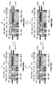
- FIG. 4 is an enlarged view of a portion B shown in FIG. 4A shows a magnetic field application process for applying a magnetic field to the magnetic working material 30
- FIG. 4B shows a refrigerant discharge process for discharging the refrigerant from the work chamber 311
- FIG. 4C shows a magnetic working material.
- 30 shows a magnetic field removal process for removing the magnetic field from 30, and (d) shows a refrigerant suction process for sucking the refrigerant into the work chamber 311.
- the piston 343 in the high temperature side bore portion 344a moves from the bottom dead center side to the top dead center side, and the refrigerant in the upper working chamber 311 is transferred to the refrigerant pump 34. It moves from the side to the high temperature side entrance 312 side.
- the discharge valve 312d provided in the refrigerant discharge part 312b of the high temperature side inlet / outlet 312 is opened, and the high-temperature refrigerant existing in the vicinity of the refrigerant discharge part 312b is discharged to the heating heat exchanger 13 side (refrigerant discharge process). .
- the piston 343 in the high temperature side bore 344a moves from the top dead center side to the bottom dead center side, and the refrigerant in the upper working chamber 311 moves to the high temperature side entrance / exit. It moves from the 312 side to the refrigerant pump 34 side.
- the suction valve 312c provided in the refrigerant suction part 312a of the high temperature side inlet / outlet 312 is opened, and the refrigerant flowing out from the heating heat exchanger 13 is sucked into the vicinity of the refrigerant suction part 312a (refrigerant suction process).
- the work chamber 311 on the lower side of the high temperature side container 31a differs from the process performed on the upper work chamber 311 side in the same manner as the upper work chamber 311 side.
- Four processes such as a discharge process, a magnetic field removal process, and a refrigerant suction process are performed.
- the piston 343 in the low temperature side bore portion 344b is top dead during the magnetic field application process on the side of the working chamber 311 above the high temperature side container 31a.
- a magnetic field is applied to the magnetic working material 30 in a state of being positioned near the point.
- the piston 343 in the low temperature side bore 344b moves from the top dead center side to the bottom dead center side, and the refrigerant in the upper working chamber 311 moves from the low temperature side inlet / outlet 313 side to the refrigerant pump 34 side.
- the suction valve 313c provided in the refrigerant suction part 313a of the low temperature side inlet / outlet 313 is opened, and the refrigerant flowing out from the cooling heat exchanger 12 is sucked into the vicinity of the refrigerant suction part 313a (refrigerant suction process).
- the piston 343 in the low temperature side bore part 344b is positioned near the bottom dead center during the magnetic field removal process on the working chamber 311 side above the high temperature side container 31a. In this state, the magnetic field is removed from the magnetic working material 30 accommodated in the upper working chamber 311.
- the piston 343 in the low temperature side bore portion 344b moves from the bottom dead center side to the top dead center side, and the refrigerant in the upper work chamber 311 moves from the refrigerant pump 34 side to the low temperature side inlet / outlet 313 side.
- the discharge valve 313d provided in the refrigerant discharge part 313b of the low temperature side inlet / outlet 313 is opened, and the low temperature refrigerant existing in the vicinity of the refrigerant discharge part 312b is discharged to the cooling heat exchanger 12 side (refrigerant discharge process).
- the work chamber 311 on the lower side of the low temperature side container 31b differs from the process performed on the upper work chamber 311 side in the same manner as the upper work chamber 311 side.
- Four processes such as an intake process, a magnetic field removal process, and a refrigerant discharge process are performed.
- the refrigerant moves from the low temperature side inlet / outlet 313 side toward the high temperature side inlet / outlet 312 side, and the magnetic working material 30 generates a magnetic field. After the removal, the refrigerant moves from the high temperature side entrance 312 side toward the low temperature side entrance 313 side.
- the magnetic field application process, the refrigerant discharge process, the magnetic field removal process, and the refrigerant suction process are repeated on the high temperature side container 31a side in the heat exchange container 31, and the magnetic field application process, the refrigerant suction process, and the magnetic field removal are performed on the low temperature side container 31b side.
- the magnetic working material 30 accommodated in the upper working chamber 311 of the high temperature side container 31a and the magnetic work accommodated in the upper working chamber 311 of the low temperature side container 31b by repeating the process and the refrigerant discharge process. A large temperature gradient between the substance 30 can be generated.
- each operation mode is appropriately determined by an operation mode changeover switch provided on the operation panel or a control process of the air conditioning control device 100.
- 5 shows the refrigerant circuit in the cooling mode
- FIG. 6 shows the refrigerant circuit in the heating mode
- FIG. 7 shows the refrigerant circuit in the dehumidifying mode.
- Cooling mode (see FIG. 5)
- the high temperature side refrigerant circuit 4 is connected to the refrigerant outlet 13b side of the heat exchanger 13 for heating and the heat exchanger 6 for absorbing and radiating heat by the first electric three-way valve 41 by a control signal from the air conditioning control device 100. Is switched to the refrigerant circuit connecting the heat radiation side refrigerant inlet 61a side.
- the low-temperature side refrigerant circuit 5 is switched to a refrigerant circuit that connects the refrigerant discharge portion 313b side of the low-temperature side inlet / outlet 313 and the third electric three-way valve 52 by the second electric three-way valve 51, and
- the three-electric three-way valve 52 is switched to a refrigerant circuit that connects the second electric three-way valve 51 and the refrigerant inlet 12a side of the cooling heat exchanger 12.
- a circulation circuit in which the refrigerant circulates in the order of the magnetic refrigerator 3 is configured.
- the low-temperature side refrigerant circuit 5 there is a circulation circuit in which the refrigerant circulates in the order of the magnetic refrigerator 3, the second electric three-way valve 51, the third electric three-way valve 52, the cooling heat exchanger 12, and the magnetic refrigerator 3. Composed.
- the refrigerant whose temperature has been raised by the magnetic refrigerator 3 is discharged from the refrigerant discharge portion 312b of the high temperature side container 31a of the magnetic refrigerator 3 to the heating heat exchanger 13 side and cooled by the heating heat exchanger 13.
- the air is cooled by exchanging heat with the blown air (cold air) after passing through the heat exchanger 12 for cooling.
- the refrigerant flowing out of the heating heat exchanger 13 is cooled by exchanging heat with the outside air in the heat radiating portion 61 of the heat absorbing and radiating heat exchanger 6, and is cooled through the refrigerant suction portion 312 a of the magnetic refrigerator 3. And then the temperature rises again.
- the refrigerant lowered in temperature by the magnetic refrigerator 3 is discharged from the low temperature side inlet / outlet 313 of the low temperature side container 31 b of the magnetic refrigerator 3 to the cooling heat exchanger 12 side and blown air by the cooling heat exchanger 12. Endothermic. As a result, the blown air passing through the cooling heat exchanger 12 is cooled.
- a part (or all) of the blown air cooled by the cooling heat exchanger 12 passes from the cold air bypass passage 16 to the mixing space 17.
- a part (or all) of the blown air cooled by the cooling heat exchanger 12 flows into the heating cool air passage 15 and passes through the heating heat exchanger 13 and the heater core 14, it is reheated. And flows into the mixing space 17.
- the temperature of the blown air mixed in the mixing space 17 and blown into the vehicle interior is adjusted to a desired temperature, and the vehicle interior can be cooled.
- the cooling mode although the dehumidifying ability of the blown air is high, the heating ability is hardly exhibited.
- (B) Heating mode (see Fig. 6)
- the high temperature side refrigerant circuit 4 in response to a control signal from the air conditioning control device 100, causes the first electric three-way valve 41 to suck the refrigerant from the refrigerant outlet 13b side of the heating heat exchanger 13 and the high temperature side container 31a. It switches to the refrigerant circuit which connects between the part 312a side.
- the low-temperature side refrigerant circuit 5 connects the refrigerant discharge section 313b side of the low-temperature side inlet / outlet 313 and the heat-absorption-side refrigerant inlet 62a side of the heat-dissipating / dissipating heat exchanger 6 by the second electric three-way valve 51.
- the third electric three-way valve 52 is switched to a refrigerant circuit that connects the second electric three-way valve 51 and the refrigerant suction portion 313a side of the low temperature side inlet / outlet 313.
- the refrigerant circulates in the order of the magnetic refrigerator 3, the heat exchanger 13 for heating, the first electric three-way valve 41, and the magnetic refrigerator 3.
- a circuit is constructed.
- the refrigerant flows in the order of the magnetic refrigerator 3, the heat absorbing portion 62 of the heat exchanger 6 for absorbing and radiating heat, the second electric three-way valve 51, the third electric three-way valve 52, and the magnetic refrigerator 3.
- a circulating circuit is circulated.
- the refrigerant whose temperature has been raised in the magnetic refrigerator 3 is discharged from the refrigerant discharge portion 312b of the high temperature side container 31a of the magnetic refrigerator 3 to the heating heat exchanger 13 side, and the blower is used in the heating heat exchanger 13 It is cooled by exchanging heat with the blown air blown from. Thereby, the blowing air which passes the heat exchanger 13 for a heating is heated.
- the opening degree of the air mix door 18 is adjusted, the temperature of the blown air mixed in the mixing space 17 and blown out into the vehicle interior is adjusted to a desired temperature in the same manner as in the cooling mode. Heating can be performed. In the heating mode, the dehumidifying ability of the blown air is not exhibited.
- the refrigerant that has flowed out of the heat exchanger 13 for heating is sucked into the high temperature side container 31a through the refrigerant suction portion 312a of the magnetic refrigerator 3 and is heated again.
- the refrigerant lowered in temperature by the magnetic refrigerator 3 is discharged from the low-temperature side inlet / outlet 313 of the low-temperature side container 31b of the magnetic refrigerator 3 to the heat-absorbing / dissipating heat exchanger 6 side.
- the temperature is raised by exchanging heat with the outside air at the unit 62.
- the refrigerant that has flowed out of the heat absorption part 62 of the heat-absorbing / dissipating heat exchanger 6 is drawn into the low-temperature side container 31b via the refrigerant suction part 313a of the magnetic refrigerator 3 and is cooled again.
- (C) Dehumidification mode (see FIG. 7)
- the high-temperature side refrigerant circuit 4 causes the first electric three-way valve 41 to suck the refrigerant from the refrigerant outlet 13b side of the heating heat exchanger 13 and the high-temperature side container 31a according to a control signal from the air conditioning control device 100. It switches to the refrigerant circuit which connects between the part 312a side.
- the low-temperature side refrigerant circuit 5 is switched to a refrigerant circuit that connects the refrigerant discharge portion 313b side of the low-temperature side inlet / outlet 313 and the third electric three-way valve 52 by the second electric three-way valve 51, and
- the three-electric three-way valve 52 is switched to a refrigerant circuit that connects the second electric three-way valve 51 and the refrigerant inlet 12a side of the cooling heat exchanger 12.
- the refrigerant circulates in the order of the magnetic refrigerator 3, the heat exchanger 13 for heating, the first electric three-way valve 41, and the magnetic refrigerator 3.
- a circuit is constructed.
- the low-temperature side refrigerant circuit 5 there is a circulation circuit in which the refrigerant circulates in the order of the magnetic refrigerator 3, the second electric three-way valve 51, the third electric three-way valve 52, the cooling heat exchanger 12, and the magnetic refrigerator 3. Composed.
- the refrigerant whose temperature has been raised by the magnetic refrigerator 3 is discharged from the refrigerant discharge portion 312b of the high temperature side container 31a of the magnetic refrigerator 3 to the heating heat exchanger 13 side and cooled by the heating heat exchanger 13.
- the air is cooled by exchanging heat with the blown air (cold air) after passing through the heat exchanger 12 for cooling. Thereby, the blowing air which passes the heat exchanger 13 for a heating is heated.
- the refrigerant lowered in temperature by the magnetic refrigerator 3 is discharged from the low temperature side inlet / outlet 313 of the low temperature side container 31 b of the magnetic refrigerator 3 to the cooling heat exchanger 12 side and blown air by the cooling heat exchanger 12. Endothermic. As a result, the blown air passing through the cooling heat exchanger 12 is cooled and dehumidified.
- the blown air cooled and dehumidified by the cooling heat exchanger 12 is reheated when passing through the heating heat exchanger 13 and the heater core 14 and blown out from the mixing space 17 into the vehicle interior.
- dehumidification in the passenger compartment can be performed.
- the dehumidifying ability of the blown air can be exhibited, but the heating ability is smaller than that in the heating mode.
- the refrigerant that has flowed out of the heat exchanger 13 for heating is sucked into the high temperature side container 31a through the refrigerant suction portion 312a of the magnetic refrigerator 3 and is heated again.
- the automotive air conditioner 1 including the magnetic refrigeration system 2 of the present embodiment operates as described above, the following excellent effects can be exhibited.
- the refrigerant is moved from the low temperature side inlet / outlet 313 side toward the high temperature side inlet / outlet 312 side.
- the refrigerant in the vicinity of the high temperature side inlet / outlet 312 side heated by the heat of the magnetic working material 30 generated by the application of the magnetic field can be caused to flow into the heating heat exchanger 13 via the high temperature side refrigerant circuit 4.
- the refrigerant is moved from the high temperature side entrance 312 side toward the low temperature side entrance 313 side,
- the refrigerant in the vicinity of the low temperature side inlet / outlet 313, which has been cooled by the cold heat of the magnetic working material 30 generated by the removal of the magnetic field, can be caused to flow into the cooling heat exchanger 12 via the low temperature side refrigerant circuit 5.
- the refrigerant heated by the heat generated in the magnetic working material 30 is directly flowed into the heat exchanger 13 for heating, and the refrigerant cooled by the cold generated in the magnetic working material 30 is directly flowed into the cooling heat exchanger 12.
- the refrigerant temperature at the high temperature side inlet / outlet 312 of the heat exchanger vessel 31 in the magnetic refrigerator 3 is Th
- the refrigerant temperature at the low temperature side inlet / outlet 313 is Tl ( ⁇ Th)
- the cycle efficiency ⁇ in the magnetic refrigeration system 2 is an ideal Carnot.
- the cycle efficiency is set to 80% with respect to the cycle efficiency ⁇ th
- the cold and hot heat of the refrigerant in the heat exchange vessel 31 is directly transported to the heating heat exchanger 13 and the cooling heat exchanger 12 as in this embodiment.
- the COP can be represented by the following formula F1.
- the heat exchange loss ⁇ T when transporting the heat and cold generated in the magnetic working material 30 to the heat exchangers 12 and 13 can be reduced.
- the COP of the magnetic refrigeration system 2 can be improved.
- the refrigerant in the work chamber 311 of the heat exchange container 31 is reciprocated between the high temperature side entrance 312 side and the low temperature side entrance 313 side. For this reason, if it was set as the structure which connected each inlet / outlet 312 and 313 of the heat exchange container 31 and each heat exchanger 12 and 13 only with piping etc., it was discharged to each heat exchanger 12 and 13 from each inlet / outlet 312 and 313. There is a possibility that the refrigerant is sucked into the work chamber 311 of the heat exchange container 31 again before flowing into the heat exchangers 12 and 13.
- the heat of the refrigerant discharged from the respective entrances 312 and 313 to the respective heat exchangers 12 and 13 is merely transmitted to the refrigerant in each of the heat exchangers 12 and 13 through the refrigerant existing in the pipe. It takes a long time to bring the refrigerant in each of the heat exchangers 12 and 13 to a desired temperature.
- heat exchange is performed by the high-temperature side refrigerant circuit 4 configured so that the refrigerant discharged from the high-temperature side entrance 312 returns to the high-temperature side entrance 312 again through the heating heat exchanger 13. Since the high temperature side inlet / outlet 312 of the container 31 is connected to the heating heat exchanger 13, the refrigerant discharged from the high temperature side inlet / outlet 312 of the heat exchange container 31 can flow into the heating heat exchanger 13.
- the refrigerant discharged from the low temperature side inlet / outlet 313 passes through the cooling heat exchanger 12 and returns to the low temperature side inlet / outlet 313 again, so that the low temperature side inlet / outlet 313 of the heat exchange vessel 31 is returned by the low temperature side refrigerant circuit 5. Since the cooling heat exchanger 12 is connected to the cooling heat exchanger 12, the refrigerant discharged from the low temperature side inlet / outlet 313 of the heat exchange container 31 can flow into the cooling heat exchanger 12.
- a suction valve that is opened when the refrigerant is sucked into the work chamber 311 of the heat exchange container 31 and the work chamber 311 of the heat exchange container 31 are respectively provided to the respective entrances 312 and 313 of the heat exchange container 31.
- a discharge valve that is opened when the refrigerant is discharged from the inside is provided.
- the refrigerant flowing out from the heating heat exchanger 13 can be sucked into the work chamber 311 of the heat exchange container 31.
- the refrigerant in the vicinity of the low temperature side inlet / outlet 313, which has been cooled by the cold heat of the magnetic working material generated by the removal of the magnetic field, can surely flow into the cooling heat exchanger 12.
- the refrigerant flowing out from the cooling heat exchanger 12 can be sucked into the work chamber 311 of the heat exchange container 31.
- the rotation shafts 321 a and 321 b of the magnetic field application removing device 32 are connected to the drive shaft 341 of the refrigerant pump 34, and the refrigerant pump 34 is driven by the electric motor 35 that is a driving unit of the magnetic field application removing device 32. It is configured to do.
- the magnetic refrigeration system 2 can be realized with a simple configuration. As a result, it is possible to further increase the COP of the magnetic refrigeration system 2 by suppressing an increase in power consumption in the magnetic refrigeration system 2.
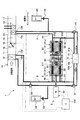
- FIG. 8 is an overall configuration diagram of the automotive air conditioner 1 of the present embodiment.
- description of the same or equivalent parts as in the first embodiment will be omitted or simplified.
- the suction valves 312c and 313c are provided in the refrigerant suction portions 312a and 313a of the respective containers 31a and 31b, and the discharge valves 312d and 313d are provided in the refrigerant discharge portions 312b and 313b.
- the refrigerant inlets 312, 313 of the containers 31a, 31b, the refrigerant inlets 12a, 13a of the heat exchangers 12, 13, the refrigerant outlets 12b, 13b of the heat exchangers the refrigerant of the containers 31a, 31b.
- the refrigerant flows in one direction in the order of the entrances 312 and 313.
- the suction valves 312c, 313c and the discharge valves 312d, 313d are eliminated, and check valves (check valves) 44, 45, 56, 57 are added to the high temperature side refrigerant circuit 4 and the low temperature side refrigerant circuit 5.
- check valves check valves
- the high temperature side refrigerant circuit 4 includes a high temperature side container 31 a between the refrigerant inlet / outlet 312 of the high temperature side container 31 a and the refrigerant inlet 13 a of the heat exchanger 13 for heating.
- a first check valve 44 is provided that allows the refrigerant to flow from the refrigerant inlet / outlet 312 side to the refrigerant inlet 13a side of the heating heat exchanger 13.
- the high temperature side refrigerant circuit 4 has a high temperature from the refrigerant outlet 13b side of the heating heat exchanger 13 between the refrigerant outlet 13b side of the heating heat exchanger 13 and the refrigerant inlet / outlet 312 of the high temperature vessel 31a.
- a second check valve 45 that allows the refrigerant to flow to the refrigerant inlet / outlet 312 side of the side container 31a is provided.
- a cooling heat exchanger is provided between the refrigerant inlet / outlet 313 of the low temperature side container 31 b and the refrigerant inlet / outlet 313 of the cooling heat exchanger 12 from the refrigerant inlet / outlet 313 side.
- a third check valve 56 that allows the refrigerant to flow toward the refrigerant inlet 13a is provided.
- the low temperature side refrigerant circuit 5 has a low temperature from the refrigerant outlet 13b side of the cooling heat exchanger 12 between the refrigerant outlet 13b side of the cooling heat exchanger 12 and the refrigerant inlet / outlet 313 of the low temperature side container 31b.
- a fourth check valve 57 that allows the refrigerant to flow to the refrigerant inlet / outlet 313 side of the side container 31b is provided.
- the refrigerant in the vicinity of the high temperature side entrance / exit 312 that has been heated by the heat of the magnetic working material 30 generated by the application of the magnetic field is reliably subjected to heat exchange for heating.
- the refrigerant flowing out of the heating heat exchanger 13 can be sucked into the working chamber 311 of the heat exchange container 31 while being allowed to flow into the vessel 13.
- the refrigerant in the vicinity of the low temperature side inlet / outlet 313, which has been cooled by the cold heat of the magnetic working material generated by the removal of the magnetic field, can surely flow into the cooling heat exchanger 12.
- the refrigerant flowing out from the cooling heat exchanger 12 can be sucked into the work chamber 311 of the heat exchange container 31.
- the 1st, 2nd check valves 44 and 45 provided in the high temperature side refrigerant circuit 4 in this embodiment comprise the 1st backflow prevention part of this indication, and the 3rd provided in the low temperature side refrigerant circuit 5,
- the fourth check valves 56 and 57 constitute the second backflow prevention unit of the present disclosure.
- FIG. 9 is an overall configuration diagram of the automotive air conditioner 1 of the present embodiment.
- description of the same or equivalent parts as in the first and second embodiments will be omitted or simplified.
- the first and second check valves 44 and 45 are provided in the high temperature side refrigerant circuit 4, and the third and fourth check valves 56 and 57 are provided in the low temperature side refrigerant circuit 5.
- the open / close valves 46, 47 instead of the check valves 44, 45, 56, 57, the open / close valves 46, 47 that open and close the refrigerant circuits 4, 5 according to control signals from the air conditioning control device 100. , 58 and 59 are provided.
- the high temperature side refrigerant circuit 4 includes a first on-off valve 46 between the refrigerant inlet / outlet 312 of the high temperature side container 31 a and the refrigerant inlet 13 a of the heat exchanger 13 for heating.
- a second on-off valve 47 is provided between the refrigerant outlet 13b side of the heating heat exchanger 13 and the refrigerant inlet / outlet 312 of the high temperature side container 31a.
- the first on-off valve 46 is controlled by the air-conditioning control device 100 to allow only the refrigerant flow from the refrigerant inlet / outlet 312 side of the high temperature side container 31a to the refrigerant inlet 13a side of the heating heat exchanger 13. .
- the second on-off valve 47 is controlled so as to allow only the refrigerant flow from the refrigerant outlet 13b side of the heat exchanger 13 for heating to the refrigerant inlet / outlet 312 side of the high temperature side container 31a.
- the low temperature side refrigerant circuit 5 is provided with a third on-off valve 58 between the refrigerant inlet / outlet 313 of the low temperature side container 31b and the refrigerant inlet / outlet 13a of the cooling heat exchanger 12, so that the cooling heat exchanger 12
- a fourth on-off valve 59 is provided between the refrigerant outlet 13b side and the refrigerant inlet / outlet 313 of the low temperature side container 31b.
- the third on-off valve 58 is controlled by the air conditioning control device 100 to allow only the refrigerant flow from the refrigerant inlet / outlet 313 side of the low temperature side container 31b to the refrigerant inlet 13a side of the cooling heat exchanger 12.
- the fourth on-off valve 59 is controlled to allow only the refrigerant flow from the refrigerant outlet 13b side of the cooling heat exchanger 12 to the refrigerant inlet / outlet 313 side of the low temperature side container 31b.
- first and second on-off valves 46 and 47 provided in the high temperature side refrigerant circuit 4 in the present embodiment constitute a first backflow prevention unit of the present disclosure
- the 4th on-off valves 58 and 59 comprise the 2nd backflow prevention part of this indication.
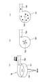
- FIG. 10 is an overall configuration diagram of the automotive air conditioner 1 of the present embodiment.
- a magnetic refrigeration system 2 having a refrigerant circuit only in a cooling mode for cooling the passenger compartment will be described.
- description of the same or equivalent parts as in the first to third embodiments will be omitted or simplified.
- the magnetic refrigeration system 2 radiates heat that circulates to the radiator (first heat exchanger) 7 the refrigerant that has been heated by the heat generated by the magnetic refrigerator 3 and the magnetic refrigerator 3.
- Side refrigerant circuit first refrigerant circulation circuit
- low temperature side refrigerant circuit second refrigerant circulation
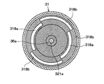
- the heat exchange container 31 of the magnetic refrigerator 3 of the present embodiment is configured by a hollow cylindrical container in which a work chamber 311 in which a magnetic working material 30 is accommodated and a refrigerant flows is formed.
- a refrigerant pump 34 is arranged coaxially on one end side of the heat exchange container 31.
- a refrigerant inlet / outlet 312 is formed on the end face opposite to the refrigerant pump 34, and a communication path 314 communicating with the cylinder bore 344 of the refrigerant pump 34 is formed on the end face on the refrigerant pump 34 side.
- the refrigerant pump 34 of the present embodiment includes a first bore part 344a corresponding to the communication path 314 of the heat exchange vessel 31 and a second bore part 344b communicating with a low-temperature side refrigerant circuit 5 described later. .
- the cylinder bore 344 is configured to allow the refrigerant in the first bore portion 344a and the refrigerant in the second bore portion 344b to flow, and the heat of the first bore portion 344a is directly transported to the second bore portion 344b.
- the communication passage 345 that communicates the second bore part 344b and the low-temperature side refrigerant circuit 5 includes a refrigerant suction part 345a that sucks the refrigerant from the low-temperature side refrigerant circuit 5, and a refrigerant discharge that discharges the refrigerant to the low-temperature side refrigerant circuit 5. It consists of a part 345b.
- the refrigerant suction part 345a of the communication path 345 is provided with a suction valve 345c that is opened when the refrigerant is sucked, and the discharge valve 345d that is opened when the refrigerant is discharged is provided in the refrigerant discharge part 345b. It has been.
- the communication passage 345 communicating with the low temperature side refrigerant circuit 5 in the refrigerant pump 34 is configured as a refrigerant inlet / outlet corresponding to the refrigerant inlet / outlet 312 in the heat exchange container 31.
- the heat radiation side refrigerant circuit 8 guides the refrigerant discharged from the refrigerant discharge portion 312b of the refrigerant inlet / outlet 312 in the heat exchange container 31 to the refrigerant inlet 7a of the radiator 7 and flows out of the refrigerant outlet 13b of the radiator 7.
- This is a refrigerant circulation circuit for returning the refrigerant to the refrigerant suction part 312a of the refrigerant inlet / outlet 312.
- the refrigerant circulates in the order of the refrigerant discharge part 312 b of the heat exchange container 31, the radiator 7, the refrigerant suction part 312 a of the heat exchange container 31.
- the radiator 7 is a heat exchanger that is arranged in the engine room and exchanges heat between the refrigerant flowing from the refrigerant inlet 7a and the outside air.
- the low temperature side refrigerant circuit 5 of the present embodiment guides the refrigerant discharged from the refrigerant discharge portion 345b of the communication passage 345 in the refrigerant pump 34 to the refrigerant inlet 12a of the cooling heat exchanger 12, and also cools the cooling heat.
- 3 is a refrigerant circulation circuit that returns the refrigerant flowing out from the refrigerant outlet 12b of the exchanger 12 to the refrigerant suction portion 345a of the communication path 345 in the refrigerant pump 34.
- the refrigerant circulates in the order of the refrigerant discharge part 345 b of the communication path 345 in the refrigerant pump 34, the cooling heat exchanger 12, the refrigerant suction part 345 a of the communication path 345 in the refrigerant pump 34.
- the piston 343 in the first bore part 344a of the refrigerant pump 34 When the piston 343 in the first bore part 344a of the refrigerant pump 34 is positioned near the bottom dead center and the permanent magnet 323a approaches the work chamber 311 on the upper side of the heat exchange vessel 31, the piston 343 is accommodated in the work chamber 311 on the upper side. Then, a magnetic field is applied to the magnetic working material 30 and the refrigerant in the upper working chamber 311 is heated (magnetic field applying process). At this time, the piston 343 in the second bore portion 344b is positioned near the top dead center.
- the piston 343 in the first bore part 344a is located near the top dead center and the permanent magnet 323a moves away from the work chamber 311 on the upper side of the heat exchange container 31, the magnetic material housed in the work chamber 311 on the upper side is stored.
- the magnetic field is removed from the working substance 30, and the temperature of the refrigerant in the upper working chamber 311 is lowered (magnetic field removing process).
- the piston 343 in the second bore portion 344b is positioned near the bottom dead center. Note that the refrigerant in the first bore part 344a, which has been cooled by removing the magnetic field from the magnetic working material 30, flows into the second bore part 344b, and the refrigerant in the second bore part 344b falls.
- the piston 343 in the first bore part 344a moves from the top dead center side to the bottom dead center side, and the refrigerant flowing out from the heating heat exchanger 13 is sucked into the vicinity of the refrigerant suction part 312a.
- the piston 343 in the second bore part 344b moves from the bottom dead center side to the top dead center side, and the refrigerant in the second bore part 344b passes through the refrigerant discharge part 345b of the communication path 345, It is discharged to the cooling heat exchanger 12 side.
- the refrigerant cooled by the cold generated in the magnetic working material 30 can be directly flowed into the cooling heat exchanger 12, the heat generated when the cold generated in the magnetic working material 30 is transported. Exchange loss can be reduced, and the COP of the magnetic refrigeration system can be improved.
- the magnetic refrigeration system 2 having the refrigerant circuit only for the cooling mode for cooling the vehicle interior has been described.
- the magnetic refrigeration system 2 has a refrigerant circuit only for the heating mode for heating the vehicle interior.
- the radiator 7 according to the present embodiment is disposed in the case 11 of the indoor air conditioning unit 10 and functions as a heat exchanger for heating that heats the air blown into the vehicle interior. What is necessary is just to arrange
- FIG. 11 is an overall configuration diagram of the automotive air conditioner 1 of the present embodiment
- FIG. 12 is an enlarged view of the magnetic refrigerator of the present embodiment.
- the specific configuration of the pair of refrigerant outlets 312 and 313 and the specific configuration of the refrigerant pump 34 in the magnetic refrigerator 3 are different from those in the first to fourth embodiments.
- description of the same or equivalent parts as in the first to fourth embodiments will be omitted or simplified.
- the refrigerant inlets 312 and 313 of the present embodiment are positioned on the same circumference when the refrigerant suction portions 312a and 313a are viewed from the longitudinal direction of the heat exchange container 31, respectively. It is provided to do.
- the refrigerant discharge portions 312b and 313b are provided so as to be positioned on the same circumference when viewed from the longitudinal direction of the heat exchange container 31.
- coolant discharge parts 312b and 313b are arrange
- Each refrigerant suction part 312a, 313a is provided with a suction valve 313c, and each refrigerant discharge part 312b, 313b is provided with a discharge valve 313d.
- each suction valve 313c is provided so that it may be located on the circumference when it sees from the longitudinal direction of the heat exchange container 31 corresponding to the refrigerant
- each discharge valve 313d is provided so as to be positioned on the same circumference when viewed from the longitudinal direction of the heat exchange container 31 corresponding to the refrigerant discharge portions 312b and 313b.
- coolant suction part 312a in the high temperature side inlet / outlet 312 is mutually connected via the suction side manifold 312e
- coolant discharge part 312b is mutually connected via the discharge side manifold 312f.
- the refrigerant suction portions 313a at the low temperature side inlet / outlet 313 communicate with each other via the suction side manifold 313e
- the refrigerant discharge portions 313b communicate with each other via the discharge side manifold 313f.
- a heat insulating member (not shown) is disposed between the suction side manifolds 312e and 313e and the discharge side manifolds 312f and 313f, and heat transfer between the manifolds is suppressed.
- the volume of the space constituting each refrigerant suction part 312a, 313a and each refrigerant discharge part 312b, 313b in the heat exchange container 31 is the refrigerant discharge volume (cylinder volume) per one time in the refrigerant pump 34 described later. ) To be smaller than.
- coolant discharge part 312b, 313b is the volume of the arrangement
- the permanent magnets 323a and 323b constituting a part of the magnetic field application / removal device 32 are provided at positions shifted by 180 ° on the outer peripheral surfaces of the rotors 322a and 322b. For example, as shown in FIG. 12, when one permanent magnet 323a is located on the upper side, the other permanent magnet 323b is located on the lower side.
- the refrigerant pump 34 of the present embodiment will be described.
- a multi-cylinder radial piston that slides the piston 346 in the radial direction with respect to the axial direction of the rotary shafts 321a and 321b.
- a pump is used as the refrigerant pump 34.
- the refrigerant pump 34 of the present embodiment is rotatably supported in a cylindrical housing 340, the housing 340, and a drive shaft integrally formed with an eccentric cam 348, radially on the housing 340.
- a plurality of cylinder bores 347 and pistons 346 that reciprocate in the cylinder bores 347 according to the rotation of the eccentric cam 348 are configured.
- the heat exchange container 31 and the housing 340 of the refrigerant pump 34 are integrated.
- the refrigerant pump 34 sucks and discharges the refrigerant to and from the containers 31a and 31b in synchronization with the application and removal of the magnetic field to the magnetic working material 30 in the same manner as the refrigerant pump described in the above embodiment. Configured to do.
- a magnetic field is applied to the magnetic working material 30 in the work chamber 311 located on the upper side in the high temperature side container 31a, and the magnetic field in the work chamber 311 located on the upper side in the low temperature side container 31b.
- the refrigerant is sequentially discharged into the work chambers 311 located on the upper side of the containers 31a and 31b, and the work chambers 311 located on the lower side of the containers 31a and 31b. The refrigerant is sucked in sequentially.
- the refrigerant pump 34 removes the magnetic field from the magnetic working material in the upper working chamber 311 in the high temperature side container 31a, and at the same time the magnetic working material in the working chamber 311 located in the upper side in the low temperature side container 31b.
- the refrigerant is sequentially sucked from the work chambers 311 located on the upper side of the containers 31 a and 31 b and sequentially into the work chambers 311 located on the lower side of the containers 31 a and 31 b. Discharge the refrigerant.
- the refrigerant can be sequentially sucked and discharged from the respective working chambers 311 in the respective containers 31a and 31b in synchronization with the application and removal of the magnetic field to and from the magnetic working substance 30.
- the refrigerant near the refrigerant discharge portions 312b and 313b in 31a and 31b can be continuously discharged to the outside.
- the piston 346 in the cylinder bore 347 located on the upper side of the refrigerant pump 34 moves from the bottom dead center side to the top dead center side, and the refrigerant in each work chamber 311 located on the upper side becomes the refrigerant pump 34 side.
- the discharge valve 312d provided in the refrigerant discharge part 312b of the high temperature side inlet / outlet 312 is opened, and the high temperature refrigerant existing in the vicinity of the refrigerant discharge part 312b is discharged to the heating heat exchanger 13 side via the discharge side manifold 312f. (Refrigerant discharge process).
- the piston 346 in the cylinder bore 347 located on the upper side in the refrigerant pump 34 moves from the top dead center side to the bottom dead center side, and the refrigerant in each work chamber 311 located on the upper side becomes the high temperature side entrance 312. It moves from the side to the refrigerant pump 34 side.
- the suction valve 312c provided in the refrigerant suction part 312a of the high temperature side inlet / outlet 312 is opened, and the refrigerant flowing out from the heating heat exchanger 13 is sucked into the vicinity of the refrigerant suction part 312a via the suction side manifold 312e. (Refrigerant suction process).
- the piston 346 of the refrigerant pump 34 returns to a position near the bottom dead center, the magnetic field application process is started again.
- the four processes such as the magnetic field application process, the refrigerant discharge process, the magnetic field removal process, and the refrigerant suction process are sequentially repeated in each work chamber 311 of the high temperature side container 31a, so that each work chamber 311 of the high temperature side container 31a is accommodated.
- the heat generated by the magnetocaloric effect of the magnetic work material 30 can be transported to the heating heat exchanger 13 side.
- each work chamber 311 located above the low temperature side container 31b is permanently connected to the work chamber 311.
- the magnet 323b moves away, and the magnetic field is sequentially removed from the magnetic work material 30 accommodated in each work chamber 311 located on the upper side (magnetic field removal process).
- the piston 346 in the cylinder bore 347 located on the upper side of the refrigerant pump 34 moves from the bottom dead center side to the top dead center side, and the refrigerant in each work chamber 311 located on the upper side becomes the refrigerant pump 34 side.
- the discharge valve 313d provided in the refrigerant discharge portion 313b of the low temperature side inlet / outlet 313 is opened, and the low temperature refrigerant in the vicinity of the refrigerant discharge portion 313b is discharged to the cooling heat exchanger 12 side through the discharge side manifold 313f. (Refrigerant discharge process).
- the piston 346 in the cylinder bore 347 located on the upper side of the refrigerant pump 34 moves from the top dead center side to the bottom dead center side, and the refrigerant in each work chamber 311 located on the upper side becomes the low temperature side inlet / outlet 313. It moves from the side to the refrigerant pump 34 side.
- the suction valve 313c provided in the refrigerant suction portion 313a of the low temperature side inlet / outlet 313 is opened, and the refrigerant flowing out from the cooling heat exchanger 12 is sucked into the vicinity of the refrigerant suction portion 313a via the suction side manifold 313e. (Refrigerant suction process).
- the piston 346 of the refrigerant pump 34 returns to the position near the bottom dead center, the magnetic field removal process is started again.
- the four processes such as the magnetic field removal process, the refrigerant discharge process, the magnetic field application process, and the refrigerant suction process are sequentially repeated in each work chamber 311 of the low temperature side container 31b, thereby being accommodated in each work room 311 of the low temperature side container 31b.
- the cold heat generated by the magnetocaloric effect of the magnetic work material 30 can be transported to the cooling heat exchanger 12 side.
- the refrigerant whose temperature has been raised by the heat generated in the magnetic working material 30 is directly flowed into the heat exchanger 13 for heating, and the refrigerant whose temperature has been lowered by the cold heat generated in the magnetic working material 30 is cooled. Since it can be made to flow directly into heat exchanger 12 for an operation, the same operation effect as a 1st embodiment mentioned above can be produced.
- the volume of the space constituting each refrigerant suction part 312a, 313a and each refrigerant discharge part 312b, 313b in the heat exchange container 31 is determined by the refrigerant per time in the refrigerant pump 34. It is configured to be smaller than the discharge volume (cylinder volume). For this reason, it is possible to suppress the refrigerant that has been heated by the heat generated in the magnetic working material 30 and the refrigerant that has been cooled by the cold heat generated in the magnetic working material 30 from staying in the heat exchange container 31, and are generated in the magnetic working material 30. Hot and cold heat can be efficiently transported to the outside of the heat exchange container 31.
- FIG. 13 is an overall configuration diagram of the automotive air conditioner 1 of the present embodiment.
- description of the same or equivalent parts as in the first to fifth embodiments will be omitted or simplified.
- suction valves 312c and 313c and the discharge valves 312d and 313d provided in the refrigerant suction portions 312a and 313a and the refrigerant discharge portions 312b and 313b in the fifth embodiment are eliminated, and check valves 44 and 45 are used instead. , 56 and 57 are provided.
- each refrigerant suction part 312a of the high temperature side container 31a is allowed to flow a refrigerant from the refrigerant outlet 13b side of the heating heat exchanger 13 to each refrigerant suction part 312a side of the high temperature side container 31a.
- a first check valve 44 is provided, and each refrigerant discharge part 312b of the high temperature side container 31a is supplied with refrigerant from each refrigerant discharge part 312b side of the high temperature side container 31a to the refrigerant inlet 13a side of the heat exchanger 13 for heating.
- a second check valve 45 that allows flow is provided.
- each refrigerant flow from the refrigerant outlet 12b side of the cooling heat exchanger 12 to the refrigerant inlet portion 313a side of the low temperature side container 31b is allowed in each refrigerant suction portion 313a of the low temperature side container 31b.
- a check valve 56 is provided, and each refrigerant discharge portion 313b of the low temperature side container 31b receives the flow of refrigerant from the refrigerant discharge portion 313b side of the low temperature side container 31b to the refrigerant inlet 12a side of the cooling heat exchanger 12.
- An allowable fourth check valve 57 is provided.
- the first and third check valves 44 and 56 provided in the refrigerant suction portions 312a and 313a correspond to the refrigerant suction portions 312a and 313a, respectively, when the heat exchange container 31 is viewed from the longitudinal direction. It arrange
- the second and fourth check valves 45 and 57 provided in the refrigerant discharge portions 312b and 313b correspond to the refrigerant discharge portions 312b and 313b, respectively, when the heat exchange container 31 is viewed from the longitudinal direction. It arrange
- the refrigerant heated by the heat generated in the magnetic working material 30 is directly flowed into the heating heat exchanger 13, and the refrigerant cooled by the cold generated in the magnetic working material 30 is cooled. Since it can be made to flow in directly, the same operation effect as a 5th embodiment mentioned above can be produced.
- FIG. 14 is an overall configuration diagram of the automotive air conditioner 1 of the present embodiment.
- description of the same or equivalent parts as in the first to sixth embodiments will be omitted or simplified.
- the check valves 44, 45, 56, and 57 provided in the respective refrigerant suction portions 312a and 313a and the respective refrigerant discharge portions 312b and 313b in the sixth embodiment are eliminated, and instead of the control from the air conditioning control device 100.
- On-off valves 46, 47, 58, 59 that open and close in response to signals are provided.
- the refrigerant flow from the refrigerant outlet 13b side of the heat exchanger 13 for heating to the refrigerant inlet portion 312a side of the high temperature side container 31a is allowed for each refrigerant suction part 312a of the high temperature side container 31a.
- the first on-off valve 46 controlled to do so is provided, and the refrigerant discharge port 312b of the high temperature side container 31a is connected to the refrigerant inlet of the heat exchanger 13 for heating from the refrigerant discharge unit 312b side of the high temperature side container 31a.
- a second on-off valve 47 is provided which is controlled so as to allow only the refrigerant flow to the 13a side.
- each refrigerant suction part 313a of the low temperature side container 31b is allowed to allow only the refrigerant flow from the refrigerant outlet 12b side of the cooling heat exchanger 12 to each refrigerant suction part 313a side of the low temperature side container 31b.
- the third on-off valve 58 controlled by the low-temperature side container 31b is provided with a third on-off valve 58, and the refrigerant discharge part 313b of the low-temperature side container 31b is connected to the refrigerant inlet 12a side of the cooling heat exchanger 12 from the refrigerant discharge part 313b side of the low-temperature side container 31b.
- a fourth on-off valve 59 is provided which is controlled so as to allow only the refrigerant flow to
- the first and third on-off valves 46 and 58 provided in the refrigerant suction portions 312a and 313a correspond to the refrigerant suction portions 312a and 313a when the heat exchange container 31 is viewed from the longitudinal direction. It arrange
- the second and fourth on-off valves 47 and 59 provided in the refrigerant discharge portions 312b and 313b correspond to the refrigerant discharge portions 312b and 313b, respectively, when the heat exchange container 31 is viewed from the longitudinal direction. It arrange
- the suction valves 312c and 313c are arranged at a position closer to the work chamber 311 than the discharge valves 312d and 313d. Therefore, when the refrigerant is discharged from the discharge valves 312d and 313d, the refrigerant accumulated in the dead space around the suction valves 312c and 313c and the refrigerant discharged from the discharge valves 312d and 313d are mixed and unnecessary. There is a risk of heat exchange.
- the discharge valves 312d and 313d are arranged closer to the work chamber 311 than the suction valves 312c and 313c in the longitudinal direction of the heat exchange vessel 31. That is, the discharge valves 312 d and 313 d are arranged close to the work chamber 311.
- the refrigerant suction portions 312a and 313a are arranged so as to be located on the radially outer side of the heat exchange container 31 with respect to the refrigerant discharge portions 312b and 313b. .
- a plate-like valve plate 316 in which a suction hole 316 a and a discharge hole 316 b are formed is disposed at a position adjacent to the work chamber 311.
- the suction hole 316 a formed in the valve plate 316 constitutes a communication hole for sucking the refrigerant into the work chamber 311, and the discharge hole 316 b serves as a communication hole for discharging the refrigerant from the work chamber 311. It is composed.
- the discharge valves 312d and 313d are arranged at positions adjacent to the valve plate 316, and the suction valves 312c and 313c are arranged at positions away from the valve plate 316 by a distance beyond the movable range of the valve. That is, the discharge valves 312d and 313d are configured to directly open and close the discharge hole 316b of the valve plate 316, and the suction valves 312c and 313c are configured to open and close the suction hole 316a of the valve plate 316 indirectly. Has been.
- the discharge valves 312d and 313d are arranged close to the work chamber 311, the refrigerant staying around the suction valves 312c and 313c and the refrigerant discharged from the work chamber 311 via the discharge valves 312d and 313d It is possible to suppress unnecessary heat exchange. Thereby, the heat exchange loss at the time of transporting the warm and cold generated in the magnetic working substance 30 can be reduced, and the COP of the magnetic refrigeration system can be improved.
- each valve 312c, 313c, 312d, and 313d is constituted by a rotary valve.
- the rotary valves constituting the valves 312c, 313c, 312d, and 313d are disposed adjacent to the work chamber 311 and communicate with the work chamber 311.
- the valve plate 317 is formed with a discharge hole 317b, and the rotary disk 318 rotates in the circumferential direction of the heat exchange vessel 31 to open and close the suction hole 317a and the discharge hole 317b of the valve plate 317.
- the suction hole 317 a formed in the valve plate 317 constitutes a communication hole for sucking the refrigerant into the work chamber 311, and the discharge hole 317 b constitutes a communication hole for discharging the refrigerant from the work chamber 311. ing.
- the rotating disk 318 is connected to the rotating shafts 321a and 321b so as to be rotated by the power of the electric motor 35 as a driving unit.
- the suction hole 317a and the discharge hole 317b of the valve plate 317 are configured to open and close at different timings in synchronization with the rotation of the rotary shafts 321a and 321b.
- the rotary disk 318 is formed with a suction side through hole 318a penetrating the front and back at a position facing the suction hole 317a of the valve plate 317 in the axial direction when the refrigerant is sucked into the working chamber 311. ing.
- the rotary disk 318 is formed with a discharge side through hole 318 b that penetrates the front and back in a position facing the discharge hole 317 b of the valve plate 317 in the axial direction. .
- each of the valves 312c, 313c, 312d, and 313d is configured as a rotary valve as in this embodiment, the refrigerant can be prevented from staying around the suction valves 312c and 313c and stay around the suction valves 312c and 313c. It is possible to suppress unnecessary heat exchange between the refrigerant and the refrigerant discharged from the work chamber 311 via the discharge valves 312d and 313d. Thereby, the heat exchange loss at the time of transporting the warm and cold generated in the magnetic working substance 30 can be reduced, and the COP of the magnetic refrigeration system can be improved.
- the magnetic refrigeration system can be realized with a simple configuration.
- the suction valves 312c and 313c and the discharge valves 312d and 313d can be integrally configured, and the magnetic refrigeration system can be realized with a simpler configuration.
- suction valves 312c and 313c are constituted by rotary valves and the discharge valves 312d and 313d are constituted by reed valves will be described.
- the rotary valves constituting the suction valves 312c and 313c are arranged adjacent to the work chamber 311 and formed with suction holes 317a communicating with the work chamber 311.
- the plate 317 includes a rotating disk 318 that rotates in the circumferential direction of the heat exchange container 31 to open and close the suction hole 317a of the valve plate 317.
- the rotating disk 318 is rotated by the power from the electric motor 35 as a drive unit so that the rotating shafts 321a and 321b are rotated.
- the suction hole 317a of the valve plate 317 is opened and closed in synchronization with the rotation of the rotary shafts 321a and 321b.
- the rotary disk 318 is formed with a suction side through hole 318a penetrating the front and back at a position facing the suction hole 317a of the valve plate 317 in the axial direction when the refrigerant is sucked into the working chamber 311.
- the reed valve constituting the discharge valves 312d and 313d is configured to open and close the discharge hole 317b formed in the valve plate 317 with a plate material having elasticity.
- the refrigerant can be prevented from staying around the suction valves 312c and 313c, and staying around the suction valves 312c and 313c. It is possible to suppress unnecessary heat exchange between the refrigerant to be discharged and the refrigerant discharged from the work chamber 311 via the discharge valves 312d and 313d. Thereby, the heat exchange loss at the time of transporting the warm and cold generated in the magnetic working material 30 can be reduced, and the COP of the magnetic refrigeration system can be improved.
- a nozzle fluid diode 71 and a spiral fluid diode 72 can be employed as the fluid diode.
- FIG. 22 is a schematic sectional view of the nozzle type fluid diode 71.
- the nozzle type fluid diode 71 has a tapered portion 71a that is reduced in a conical shape from the refrigerant flow upstream side to the refrigerant flow downstream side in the refrigerant flow path. Has been.
- the resistance in the tapered portion 71a is larger than when the refrigerant flows in the forward direction (see the white arrow in the figure). Becomes larger.
- FIG. 23A and 23B are explanatory views for explaining the spiral fluid diode 72.
- FIG. 23A is a schematic perspective view
- FIG. 23B is a flow diagram of the refrigerant in the forward direction. It is a top view and (c) is a top view of (b) which shows the flow to the reverse direction of a refrigerant
- the spiral fluid diode 72 is provided so as to extend in the direction of the central axis of the vortex chamber 721 having a cylindrical vortex chamber formed therein, and the vortex chamber in the vortex case 721.
- the shaft nozzle 722 is configured to have a tangential nozzle 723 provided so as to extend in the tangential direction of the outer periphery of the vortex chamber.
- the refrigerant from the shaft nozzle 722 enters the vortex chamber in the vortex case 721 as shown by the white arrow in FIG. And flows to the tangential nozzle 723 without generating a vortex.
- the drive source of the refrigerant pump 34 and the magnetic field application / removal device 32 is preferably configured by a single electric motor 35.
- the drive source of the refrigerant pump 34 and the magnetic field application / removal device 32 is used. It is good also as a structure provided separately.
- the drive source of each of the valves 312c, 313c, 312d, and 313d and the drive source of the magnetic field application removing device 32 be configured by one electric motor 35. It is good also as a structure which provides a source separately.
Landscapes
- Engineering & Computer Science (AREA)
- Physics & Mathematics (AREA)
- Thermal Sciences (AREA)
- Mechanical Engineering (AREA)
- General Engineering & Computer Science (AREA)
- Air-Conditioning For Vehicles (AREA)
- Chemical & Material Sciences (AREA)
- Combustion & Propulsion (AREA)
- Hard Magnetic Materials (AREA)
Abstract
冷媒移動部(34)は、磁場印加除去部(32)によって磁気作業物質(30)に磁場を印加された後に、一方の冷媒出入口(312)の冷媒吐出部(312b)から第1冷媒循環回路(4)へ冷媒を流出させ、前記磁場印加除去部(32)によって前記磁気作業物質(30)から磁場を除去された後に、他方の冷媒出入口(313)の冷媒吐出部(313b)から第2冷媒循環回路(5)へ冷媒を流出させるように構成される磁気冷凍システム。
Description
本開示は、2011年1月27日に出願された日本出願番号2011-14914号、2011年5月17日に出願された日本出願番号2011-110206号、および2011年12月22日に出願された日本出願番号2011-281288号に基づくもので、ここにその記載内容を援用する。
本開示は、磁気冷凍システム、および磁気冷凍システムを適用した自動車用空調装置に関する。
従来、磁性体等の磁気作業物質に磁場を加えると磁気作業物質が発熱し、磁場を除去すると磁気作業物質の温度が下がる現象(磁気熱量効果)を利用した磁気冷凍システムが提案されている(例えば、特許文献1参照)。
この特許文献1の磁気冷凍システムは、鉄道車両に搭載された磁気作業物質、当該磁気作業物質に磁場を作用させる強力磁場発生装置、強力磁場発生装置からの磁場が増大する際に上昇する磁気作業物質の熱(温熱)を移送する熱媒体が流通する第1の熱交換流路、強力磁場発生装置からの磁場が減少する際に低下する磁気作業物質の熱(冷熱)を移送する熱媒体が流通する第2の熱交換流路、各熱交換流路それぞれに配設されたポンプおよび熱交換器等を備えて構成されている。
そして、強力磁場発生装置からの磁場が増大する際に、第1の熱交換流路に設けられたポンプを作動させ、磁気作業物質の温熱により昇温した熱媒体を熱交換器で車室外空気と熱交換させると共に、強力磁場発生装置からの磁場が減少する際に、第2の熱交換流路に設けられたポンプを作動させ、磁気作業物質の冷熱により降温した熱媒体を熱交換器で車室内空気と熱交換させるようにしている。
ところで、特許文献1の磁気冷凍システムでは、磁気作業物質での温度変化を大きくするために強力磁場発生装置を超伝導コイル等で構成しており、その用途が特殊なものに限られ、自動車用の空調装置等の汎用製品へ適用することが困難である。
このような課題の解決手段として、磁気作業物質へ印加する磁場を増大させた後に磁気作業物質における一端側(高温端側)に冷媒(磁気熱輸送媒体)を移動させ、磁気作業物質へ印加する磁場を減少させた後に磁気作業物質における他端側(低温端側)に冷媒を移動させことにより、磁気熱量効果により生成された冷熱および温熱を磁気作業物質自体に蓄えるAMR(Active Magnetic Refrigerator)方式の磁気冷凍システムが知られている。
AMR方式の磁気冷凍システムでは、一般に、内部に磁気作業物質が充填されると共に冷媒が流通する冷媒流路が形成された容器を有し、磁気作業物質への磁場の印加・除去に応じて、冷媒を容器の一端側および他端側の間を往復移動させる構成とされている。
そして、(i)磁気作業物質に磁場を印加、(ii)磁気作業物質に生ずる温熱を冷媒により容器の一端側(高温端側)に輸送、(iii)磁気作業物質から磁場を除去、(iv)磁気作業物質に生ずる冷熱を冷媒により容器の他端側(低温端側)に輸送、といった4つの過程を繰り返すことにより、容器内の磁気作業物質に温度勾配が生まれ、容器における高温端と低温端との間に大きな温度差が生成される。
ここで、AMR方式の磁気冷凍システムを特許文献1の磁気冷凍システムに適用することが考えられるが、この場合には、磁気冷凍システムの冷凍成績係数(COP:Coefficient Of Performance)が低下するといった問題がある。なお、COPは、消費電力1kW当りの冷房・暖房能力を表したものである。
その理由としては、AMR方式の磁気冷凍システムを特許文献1の磁気冷凍システムに適用する場合、磁気作業物質の周りで、冷媒流路を流れる冷媒と熱交換流路を流れる熱媒体とを熱交換させることになり、磁気作業物質の熱が間接的に熱交換流路を流れる熱媒体に伝わり、磁気作業物質と熱媒体との間における熱交換ロスが大きくなるからである。
本開示は磁気冷凍システム、および磁気冷凍システムを適用した自動車用空調装置を提供することを目的とする。
本開示の一例にかかる磁気冷凍システムは、磁気熱量効果を有する磁気作業物質が配置されると共に冷媒が流通する複数の作業室が周方向に放射状に形成された円筒状の容器と、磁気作業物質への磁場の印加および除去を繰り返す磁場印加除去部と、容器における長手方向の両端面に設けられた一対の冷媒出入口のうち、一方の冷媒出入口の冷媒吐出部から流出した冷媒が第1熱交換器を通って一方の冷媒出入口の冷媒吸入部に戻るように構成される第1冷媒循環回路と、一対の出入口のうち、他方の冷媒出入口の冷媒吐出部から流出した冷媒が第2熱交換器を通って他方の冷媒出入口の冷媒吸入部に戻るように構成される第2冷媒循環回路と、一方の冷媒出入口側と他方の冷媒出入口側との間で冷媒を移動させる冷媒移動部と、を備え、冷媒移動部は、磁場印加除去部によって磁気作業物質に磁場を印加された後に、他方の冷媒出入口側から一方の冷媒出入口側へ冷媒を移動させ、磁場印加除去部によって磁気作業物質から磁場を除去された後に、一方の冷媒出入口側から他方の冷媒出入口側へ冷媒を移動させる。
これによると、磁気作業物質に磁場が印加された後に、作業室における他方の冷媒出入口側から一方の冷媒出入口側へ冷媒を移動させることで、磁場の印加により生ずる磁気作業物質の温熱によって昇温した一方の冷媒出入口付近の冷媒を、第1冷媒循環回路を介して第1熱交換器に流入させることができる。
また、磁気作業物質から磁場が除去された後に、作業室における一方の冷媒出入口側から他方の冷媒出入口側へ冷媒を移動させることで、磁場の除去によって生ずる磁気作業物質の冷熱によって降温した他方の冷媒出入口付近の冷媒を、第2冷媒循環回路を介して第2熱交換器に流入させることができる。
これにより、磁気作業物質に生ずる温熱により昇温した冷媒を第1熱交換器に直接流入させると共に、磁気作業物質に生ずる冷熱により降温した冷媒を第2熱交換器に直接流入させることができるので、磁気作業物質に生ずる温熱および冷熱を輸送する際の熱交換ロスを低減することができ、磁気冷凍システムのCOPの向上を図ることができる。
なお、作業室における他方の冷媒出入口側から一方の冷媒出入口側へ冷媒が移動する際には、第2熱交換器を通った冷媒が、第2冷媒循環回路から他方の冷媒出入口を介して作業室に流入することになる。また、作業室における一方の冷媒出入口側から他方の冷媒出入口側へ冷媒が移動する際には、第1熱交換器を通った冷媒が、第1冷媒循環回路から一方の冷媒出入口を介して作業室に流入することになる。
特に、冷媒吸入部および冷媒吐出部を構成する空間の容積を、冷媒移動部における一回当りの冷媒の吐出容積よりも小さくすることで、磁気作業物質に生ずる温熱により昇温した冷媒、および磁気作業物質に生ずる冷熱により降温した冷媒が容器内で滞留することを抑制することができる。つまり、磁気作業物質に生ずる温熱により昇温した冷媒、および磁気作業物質に生ずる冷熱により降温した冷媒を、効率よく容器の外部に吐出することができる。
また、冷媒吸入部には、作業室内に冷媒を吸入する際に開放される吸入弁が設けられ、冷媒吐出部には、作業室から冷媒を吐出する際に開放される吐出弁が設けられている。
これによると、磁気作業物質に磁場が印加された後に、磁場の印加によって生ずる磁気作業物質の温熱によって昇温した一方の冷媒出入口付近の冷媒を、確実に第1冷媒循環回路を介して第1熱交換器に流入させることができると共に、第2熱交換器から流出した冷媒を他方の冷媒出入口から作業室に吸入することができる。
また、磁気作業物質から磁場が除去された後に、磁場の除去によって生ずる磁気作業物質の冷熱によって降温した他方の冷媒出入口付近の冷媒を、確実に第2冷媒循環回路を介して第2熱交換器に流入させることができると共に、第1熱交換器から流出した冷媒を一方の冷媒出入口から作業室に吸入することができる。
また、吐出弁は、容器の長手方向において、吸入弁よりも作業室に近い位置に配置されている。
このように、吐出弁を作業室に近接する配置形態とすれば、吸入弁の周囲に滞留する冷媒と吐出弁を介して作業室から吐出する冷媒との不必要な熱交換を抑制することが可能となる。これにより、磁気作業物質に生ずる温熱および冷熱を輸送する際の熱交換ロスを低減することができ、磁気冷凍システムのCOPの向上を図ることができる。
また、吸入弁および吐出弁のうち、少なくとも吸入弁は、作業室に隣接して配置されると共に作業室内と連通する連通孔が形成されたバルブプレート、および容器の周方向に回転して連通孔を開閉する回転ディスクを有するロータリ弁で構成されている。
これによれば、吸入弁周囲における冷媒の滞留を抑制することができ、吸入弁周囲に滞留する冷媒と、吐出弁を介して作業室から吐出する冷媒との不必要な熱交換を抑制することが可能となる。これにより、磁気作業物質に生ずる温熱および冷熱を輸送する際の熱交換ロスを低減することができ、磁気冷凍システムのCOPの向上を図ることができる。
また、ロータリ弁を、磁場印加除去部を駆動するための動力を利用して回転ディスクが回転する構成とすれば、磁気冷凍システムを簡素な構成で実現することができる。
また、一方の冷媒出入口における冷媒吸入部および冷媒吐出部には、冷媒吐出部、第1熱交換器における冷媒流入口、第1熱交換器における冷媒流出口、冷媒吸入部といった順に冷媒が一方向へ流れることを許容する第1逆流防止部が設けられ、他方の冷媒出入口における冷媒吸入部および冷媒吐出部には、冷媒吐出部、第2熱交換器における冷媒流入口、第2熱交換器における冷媒流出口、冷媒吸入部といった順に冷媒が一方向へ流れることを許容する第2逆流防止部が設けられている。
これによっても、磁気作業物質に磁場が印加された後に、磁場の印加によって生ずる磁気作業物質の温熱によって昇温した一方の冷媒出入口付近の冷媒を、確実に第1冷媒循環回路を介して第1熱交換器に流入させることができると共に、第2熱交換器から流出した冷媒を他方の冷媒出入口から作業室に吸入することができる。
また、磁気作業物質から磁場が除去された後に、磁場の除去によって生ずる磁気作業物質の冷熱によって降温した他方の冷媒出入口付近の冷媒を、確実に第2冷媒循環回路を介して第2熱交換器に流入させることができると共に、第1熱交換器から流出した冷媒を一方の冷媒出入口から作業室に吸入することができる。
また、第1逆流防止部および第2逆流防止部の少なくとも一方を、冷媒流れの逆方向に比べて冷媒流れの順方向に抵抗が小さい流体ダイオードで構成することで、磁気冷凍システムを簡素な構成で実現することができる。
また、冷媒吸入部および冷媒吐出部を、複数の作業室に対応して複数設けるときには、冷媒吸入部を、容器の長手方向から見たときに同円周上に位置するように設け、冷媒吐出部を、容器の長手方向から見たときに同円周上に位置するように設けることが好ましい。
具体的には、磁場印加除去部を、磁場を発生させる磁場発生部、磁場発生部を回転可能に支持する回転軸、回転軸を駆動する駆動部を含んで構成し、磁場発生部を、回転軸の回転に伴って周期的に磁気作業物質に近づくように設ける構成とすることで、磁場印加除去部によって磁気作業物質への磁場の印加および除去を周期的に繰り返すことができる。
また、駆動部による動力を冷媒移動部に伝達する動力伝達機構を備え、冷媒移動部は、動力伝達機構を介して伝達された動力により、一方の冷媒出入口および他方の冷媒出入口との間で冷媒を往復移動させる。
このように、冷媒移動部を磁場印加除去部の駆動部の動力によって、駆動させる構成とすれば、冷媒移動部および磁場印加除去部の駆動源を共通化させることができるので、磁気冷凍システムを簡素な構成で実現することができる。ひいては、磁気冷凍システムにおける消費動力の増大を抑制して、磁気冷凍システムのCOPの更なる向上を図ることが可能となる。
また、冷媒移動部としては、複数の作業室に対応する複数のシリンダおよび複数のピストンを有する多気筒型のピストンポンプで構成することが好ましい。
また、上記磁気冷凍システムが適用された自動車用空調装置において、車室内に送風する送風空気の空気流路を構成するケースを備え、第1熱交換器にて車室内に送風する送風空気を加熱する加熱用熱交換器を構成し、第2熱交換器にて車室内に送風する送風空気を冷却する冷却用熱交換器を構成することで、車室内の冷房および暖房を行うことが可能となる。
具体的には、第1熱交換器を、ケース内における第2熱交換器よりも送風空気の空気流れ下流側に配置する構成とすれば、第2熱交換器にて冷却して除湿した送風空気を第1熱交換器にて加熱することで、車室内の暖房時に送風空気の除湿を行うことができる。
また、第1熱交換器に流入する送風空気の風量を調整して車室内に吹き出す空気の温度を調整する温度調整部を備える構成としてもよい。
本開示についての上記目的およびその他の目的、特徴や利点は、添付の図面を参照しながら下記の詳細な記述により、より明確になる。
第1実施形態に係る自動車用空調装置の全体構成図である。
第1実施形態に係る磁気冷凍機の拡大図である。
図2のA-A断面図である。
第1実施形態に係る磁気冷凍機の動作原理を説明する説明図である。
第1実施形態に係る自動車用空調装置の冷房モード時の冷媒回路を示す全体構成図である。
第1実施形態に係る自動車用空調装置の暖房モード時の冷媒回路を示す全体構成図である。
第1実施形態に係る自動車用空調装置の除湿モード時の冷媒回路を示す全体構成図である。
第2実施形態に係る自動車用空調装置の全体構成図である。
第3実施形態に係る自動車用空調装置の全体構成図である。
第4実施形態に係る自動車用空調装置の全体構成図である。
第5実施形態に係る自動車用空調装置の全体構成図である。
第5実施形態に係る磁気冷凍機の拡大図である。
第6実施形態に係る自動車用空調装置の全体構成図である。
第7実施形態に係る自動車用空調装置の全体構成図である。
第8実施形態に係る磁気冷凍機の要部拡大図である。
第9実施形態に係る磁気冷凍機の拡大図である。
図16のB-B断面図である。
図16のC-C断面図である。
第10実施形態に係る磁気冷凍機の拡大図である。
図19のD-D断面図である。
図19のE-E断面図である。
第11実施形態に係るノズル式流体ダイオードの模式的な断面図である。
第11実施形態に係る渦巻き式流体ダイオードを説明する説明図である。
以下、本開示の実施形態について図に基づいて説明する。なお、以下の各実施形態相互において、互いに同一もしくは均等である部分には、図中、同一符号を付してある。
(第1実施形態)
本開示の第1実施形態について図1~図7に基づいて説明する。図1は、本実施形態の自動車用空調装置1の全体構成図である。本実施形態では、本開示の磁気冷凍システム2を、自動車の車室内の空調を行う自動車用空調装置1に適用している。
本開示の第1実施形態について図1~図7に基づいて説明する。図1は、本実施形態の自動車用空調装置1の全体構成図である。本実施形態では、本開示の磁気冷凍システム2を、自動車の車室内の空調を行う自動車用空調装置1に適用している。
本実施形態の自動車用空調装置1は、内燃機関(エンジン)から車両走行用の駆動力を得る自動車に搭載される空調装置である。
自動車用空調装置1は、図1に示すように、エンジンルーム内に配置される磁気冷凍システム2、車室内に配置される室内空調ユニット10、空調制御装置100を備えている。
本実施形態の磁気冷凍システム2は、車室内を冷房する冷房モード、車室内を暖房する暖房モード、車室内の暖房時に除湿を行う除湿モードの冷媒回路を切替え可能に構成されており、自動車用空調装置1において車室内の冷房、暖房、除湿を行うことができる。
具体的には、本実施形態の磁気冷凍システム2は、磁気熱量効果により生成された冷熱および温熱を磁気作業物質30自体に蓄えるAMR方式を採用している。本実施形態の磁気冷凍システム2は、磁気熱量効果により冷熱および温熱を生成する磁気冷凍機3、磁気冷凍機3で生成した温熱により昇温した冷媒を加熱用熱交換器(第1熱交換器)13に循環させる高温側冷媒回路(第1冷媒循環回路)4、磁気冷凍機3で生成した冷熱により降温した冷媒を冷却用熱交換器(第2熱交換器)12に循環させる低温側冷媒回路(第2冷媒循環回路)5等を備えて構成されている。
磁気冷凍機3は、内部に磁気熱量効果を有する磁気作業物質30が収容されると共に熱輸送媒体である冷媒(例えば、水や不凍液)が流通する作業室311が形成された熱交換容器31、磁気作業物質への磁場の印加・除去を行う磁場印加除去装置32、熱交換容器31内の冷媒を移動させる冷媒ポンプ34、磁気冷凍機3の駆動源である電動モータ35等を有して構成されている。
図2は、磁気冷凍機3の拡大図であり、図3は、図2のA-A断面図である。なお、説明の便宜のため、図2では、磁気冷凍機3の軸方向断面を示している。
図2に示すように、本実施形態の熱交換容器31は、磁気熱量効果により温熱を生成するための高温側容器31aと磁気熱量効果により冷熱を生成するための低温側容器31bに分割されている。高温側容器31aおよび低温側容器31bは、冷媒ポンプ34を介して同軸方向に並んで配置されている。
高温側容器31aおよび低温側容器31bは、円筒状の容器で構成されている。各容器31a、31bは、外殻を構成する壁部に磁気作業物質30を収容すると共に冷媒が流通する作業室311が形成されている。なお、図3に示すように、各容器31a、31bには、周方向に放射状に複数の作業室311が形成されている。
また、熱交換容器31の両端側(各容器31a、31bにおける冷媒ポンプ34と反対側)の端面に一対の冷媒出入口312、313が形成されており、一対の冷媒出入口312、313を介して、冷媒の吸入および吐出が可能となっている。
また、各容器31a、31bにおける冷媒ポンプ34側の端面には、後述する冷媒ポンプ34のシリンダボア344内に連通する連通路314、315が形成されている。なお、当該連通路314、315は、各高温側出入口312および各低温側出入口313に対応して複数形成されている。
一対の冷媒出入口312、313のうち、高温側容器31aに形成された高温側出入口312は、高温側容器31aの各作業室311に対応して設けられており、対応する作業室311に連通している。
各高温側出入口312は、冷媒を吸入する冷媒吸入部312a、および冷媒を吐出する冷媒吐出部312bを有して構成されている。そして、冷媒吸入部312aには、冷媒を吸入する際に開放されるサクションバルブ(吸入弁)312cが設けられ、冷媒吐出部312bに冷媒を吐出する際に開放されるディスチャージバルブ(吐出弁)312dが設けられている。本実施形態のサクションバルブ312cおよびディスチャージバルブ312dは、弾力性を有する板材の一端を固定して構成されるリード弁で構成されている。
また、一対の冷媒出入口312、313のうち、低温側容器31bに形成された低温側出入口313は、低温側容器31bの各作業室311に対応して設けられており、対応する作業室311に連通している。
各低温側出入口313は、高温側出入口312と同様に、冷媒吸入部313aおよび冷媒吐出部313bを有し、冷媒吸入部313aにサクションバルブ313cが設けられ、冷媒吐出部313bにディスチャージバルブ313dが設けられている。
また、各容器31a、31bにおける冷媒ポンプ34側の端面には、後述する冷媒ポンプ34のシリンダボア344内に連通する連通路314、315が形成されている。なお、当該連通路314、315は、各高温側出入口312および各低温側出入口313に対応して複数形成されている。
各容器31a、31bそれぞれの内部には、磁場印加除去装置32の一部を構成する回転軸321a、321b、回転軸321a、321bに固定されたロータ(回転子)322a、322b、およびロータ322a、322bの外周面に埋設された永久磁石323a、323bが収容されている。
各回転軸321a、321bそれぞれは、各容器31a、31bの長手方向両端部に設けられた支持部材36a、36bにより回転可能に支持されている。
そして、高温側容器31aに収容された高温側回転軸321aは、冷媒ポンプ34側の端部が、高温側容器31aの外部に延在し、後述する冷媒ポンプ34の駆動軸341に、後述する変速機構37aを介して接続されている。
また、低温側容器31bに収容された低温側回転軸321bは、冷媒ポンプ34側の端部が、低温側容器31bの外部に延在し、後述する冷媒ポンプ34の駆動軸341に、後述する変速機構37bを介して接続されている。さらに、低温側回転軸321bは、冷媒ポンプ34と反対側の端部が、低温側容器31bの外部に延在し、各回転軸321a、321bを回転させる後述する電動モータ35が接続されている。
各ロータ322a、322bは、外周面に永久磁石323a、323bが設けられた状態で、各容器31a、31bの内周面に対して所定の空隙を空けて回転するように回転軸321a、321bに固定されている。
また、永久磁石323a、323bは、図3に示すように、各回転軸321a、321bの回転に応じて、各容器31a、31bにおける上方側の作業室311および下方側の作業室311に周期的に近づくように、ロータ322a、322bにおける外周面(例えば、約1/4の範囲)に設けられている。
これにより、回転軸321a、321bの回転に応じて、永久磁石323a、323bの周囲に生ずる磁場が、各容器31a、31bにおける永久磁石323a、323bに近い側に収容された磁気作業物質30に印加され、永久磁石323a、323bに対して遠い側に設けられた磁気作業物質30から除去される。
冷媒ポンプ34は、熱交換容器31に形成された高温側出入口312側と低温側出入口313側との間で冷媒を往復移動させる冷媒移動部を構成している。本実施形態では、冷媒ポンプ34として、一つの駆動軸341により二つの圧縮機構が同軸上に作動するタンデム型のピストンポンプを作用している。
具体的には、本実施形態の冷媒ポンプ34は、図2に示すように、ハウジング340、ハウジング340内に回転可能に支持された駆動軸341、駆動軸341に対して傾いた傾斜面を有して駆動軸341と一体的に回転する斜板342、斜板342の回転に応じて往復動するピストン343、ハウジング340におけるピストン343の両側に形成されたシリンダボア344等で構成されている。
駆動軸341は、ハウジング340の長手方向両端部に設けられた支持部材340a、340bにより回転可能に支持されている。そして、駆動軸341は、その両端部がハウジング340の外部に延在し、各変速機構37a、37bを介して高温側回転軸321aおよび低温側回転軸321bに接続されている。
ここで、各変速機構37a、37bは、電動モータ35に連結された低温側回転軸321bを介して、電動モータ35による動力を冷媒ポンプ34に伝達する動力伝達機構を構成する。本実施形態の各変速機構37a、37bは、冷媒ポンプ34の駆動軸341の回転数に対する各回転軸321a、321bの回転数の比(減速比)を調整可能に構成されている。なお、減速比は、回転軸321a、321bに固定された永久磁石323a、323bの極数に応じて決定される。例えば、永久磁石323a、323bの数がn極の場合、冷媒ポンプ34の駆動軸341がn回転したときに回転軸321a、321bが一回転するように減速比を1/nに決定することができる。
シリンダボア344は、高温側容器31aの各連通路314に対応する高温側ボア部344a、低温側容器31bの各連通路315に対応する低温側ボア部344bを有して構成されている。なお、シリンダボア344は、高温側ボア部344a内の冷媒と低温側ボア部344b内の冷媒とが熱交換可能に構成されている。
ここで、本実施形態の冷媒ポンプ34は、磁気作業物質30への磁場の印加、除去に同期して、各容器31a、31bに対する冷媒の吸入、吐出を行うように構成されている。
例えば、冷媒ポンプ34は、各容器31a、31bにおける上方側に位置する各作業室311内の磁気作業物質30に磁場が印加された際に、高温側容器31aにおける上方側に位置する各作業室311に冷媒を順次吐出すると共に、低温側容器31bにおける上方側に位置する各作業室311から冷媒を順次吸入するように構成されている。この際、冷媒ポンプ34によって、高温側容器31aにおける下方側に位置する各作業室311から冷媒が順次吸入されると共に、低温側容器31bにおける下方側に位置する各作業室311に冷媒が順次吐出される。
一方、冷媒ポンプ34は、各容器31a、31bにおける上方側に位置する各作業室311内の磁気作業物質30から磁場が除去された際に、高温側容器31aにおける上方側に位置する各作業室311から冷媒を順次吸入すると共に、低温側容器31bにおける上方側に位置する各作業室311に冷媒を順次吐出するように構成されている。
そして、冷媒ポンプ34によって、各容器31a、31bの作業室311に冷媒が吐出されると、各容器31a、31bの冷媒吐出部312b、313bに設けられたディスチャージバルブ312d、313dが開放されて、各容器31a、31bにおける冷媒吐出部312b、313b付近の冷媒が外部に吐出される。
また、冷媒ポンプ34によって、各容器31a、31bの作業室311から冷媒が吸入されると、各容器31a、31bの冷媒吸入部312a、313aに設けられたサクションバルブ312c、313cが開放されて、各容器31a、31bにおける冷媒吸入部312a、313a付近に外部から冷媒が導入される。
このように磁気冷凍機3では、磁気作業物質30への磁場の印加、除去に同期して、各容器31a、31bにおける各作業室311から順次冷媒を吸入、吐出することができるので、各容器31a、31bにおける冷媒吐出部312b、313b付近の冷媒を連続して外部に吐出することができる。
図1に戻り、電動モータ35は、車載されたバッテリ(図示略)からの電源供給により作動し、回転軸321a、321bおよび駆動軸341に動力を付与して、磁気冷凍機3を駆動する駆動部である。
ここで、本実施形態では、各容器31a、31bに収容された回転軸321a、321b、ロータ322a、322b、永久磁石323a、323b、および熱交換容器31の外部に設けられた電動モータ35が、磁場印加除去部である磁場印加除去装置32を構成している。また、永久磁石323a、323bは、磁場を発生させる磁場発生部を構成している。
次に、高温側冷媒回路4および低温側冷媒回路5について説明する。まず、高温側冷媒回路4について説明すると、高温側冷媒回路4は、高温側容器31aにおける高温側出入口312の冷媒吐出部312bから吐出された冷媒を、加熱用熱交換器13の冷媒流入口13aに導く共に、加熱用熱交換器13の冷媒流出口13bから流出した冷媒を高温側出入口312の冷媒吸入部312aに戻す冷媒循環回路である。
具体的には、高温側出入口312の冷媒吐出部312b側には、加熱用熱交換器13の冷媒流入口13a側が接続されている。加熱用熱交換器13は、後述する室内空調ユニット10のケース11内に配置されて、その内部を流通する冷媒と、後述する冷却用熱交換器12通過後の送風空気とを熱交換させることで、送風空気を加熱する熱交換器(第1熱交換器)である。
加熱用熱交換器13の冷媒流出口13b側には、第1電気式三方弁41が接続されている。第1電気式三方弁41は、空調制御装置100から出力される制御信号によって、その作動が制御される流路切替部を構成している。
より具体的には、第1電気式三方弁41は、空調制御装置100からの制御信号に応じて、加熱用熱交換器13の冷媒流出口13b側と高温側容器31aの冷媒吸入部312a側との間を接続する冷媒回路、および加熱用熱交換器13の冷媒流出口13b側と吸放熱用熱交換器6の放熱側冷媒流入口61a側との間を接続する冷媒流路を切り替える。
吸放熱用熱交換器6は、エンジンルーム内に配置されて、その内部を流通する冷媒と外気とを熱交換させる室外熱交換器である。本実施形態の吸放熱用熱交換器6は、加熱用熱交換器13から流出した冷媒が流れる放熱部61、および低温側容器31bから吐出された冷媒が流れる吸熱部62といった二つの熱交換部を有して構成されている。
吸放熱用熱交換器6の放熱部61は、放熱側冷媒流入口61aから流入した冷媒(加熱用熱交換器13から流出した冷媒)と外気とを熱交換させる熱交換部である。また、吸放熱用熱交換器6の吸熱部62は、吸熱側冷媒流入口62aから流入した冷媒(低温側容器31bから吐出された冷媒)と外気とを熱交換させる熱交換部である。
なお、放熱部61および吸熱部62は、吸放熱用熱交換器6の内部において放熱部61を流れる冷媒と吸熱部62を流れる冷媒が混在しないように、互いに冷媒流路が独立して構成されている。
吸放熱用熱交換器6における放熱側冷媒流出口61b側には、高温側容器31aの冷媒吸入部312aが接続されており、吸放熱用熱交換器6にて放熱された冷媒が高温側容器31aの作業室311に戻る。
従って、高温側冷媒回路4は、高温側容器31aの冷媒吐出部312b、加熱用熱交換器13、第1電気式三方弁41、高温側容器31aの冷媒吸入部312aといった順に冷媒が循環する循環回路と、高温側容器31aの冷媒吐出部312b、加熱用熱交換器13、第1電気式三方弁41、吸放熱用熱交換器6の放熱部61、高温側容器31aの冷媒吸入部312aといった順に冷媒が循環する循環回路とで構成される。
なお、高温側冷媒回路4には、加熱用熱交換器13と第1電気式三方弁41との間には、固定絞り42を介して、高温側冷媒回路4内の冷媒量を調整するためのリザーバタンク43が接続されている。なお、固定絞り42としては、オリフィスやキャピラリチューブ等を採用することができる。
また、低温側冷媒回路5は、低温側容器31bにおける低温側出入口313の冷媒吐出部313bから吐出された冷媒を、冷却用熱交換器12の冷媒流入口12aに導く共に、冷却用熱交換器12の冷媒流出口12bから流出した冷媒を低温側出入口313の冷媒吸入部313aに戻す冷媒循環回路である。
具体的には、低温側出入口313の冷媒吐出部313b側には、第2電気式三方弁51が接続されている。第2電気式三方弁51は、第1電気式三方弁41と同様に、空調制御装置100から出力される制御信号によって、その作動が制御される流路切替部を構成している。
第2電気式三方弁51は、空調制御装置100からの制御信号に応じて、低温側出入口313の冷媒吐出部313b側と吸放熱用熱交換器6の吸熱側冷媒流入口62a側との間を接続する冷媒回路、および低温側出入口313の冷媒吐出部313b側と第3電気式三方弁52との間を接続する冷媒回路を切り替える。そして、吸放熱用熱交換器6の吸熱側冷媒流出口62b側には、第3電気式三方弁52が接続されている。
第3電気式三方弁52は、第1、第2電気式三方弁41、51と同様に、空調制御装置100から出力される制御信号によって、その作動が制御される流路切替部を構成している。
具体的には、第3電気式三方弁52は、第2電気式三方弁51に連動して作動するように構成されている。すなわち、第3電気式三方弁52は、第2電気式三方弁51にて低温側出入口313の冷媒吐出部313b側と第3電気式三方弁52との間を接続する冷媒回路に切り替えられると、第2電気式三方弁51と冷却用熱交換器12の冷媒流入口12a側との間を接続する冷媒回路に切り替える。また、第3電気式三方弁52は、第2電気式三方弁51にて低温側出入口313の冷媒吐出部313b側と吸放熱用熱交換器6の吸熱側冷媒流入口62a側との間を接続する冷媒回路に切り替えられると、第2電気式三方弁51と低温側出入口313の冷媒吸入部313a側との間を接続する冷媒回路に切り替える。
第3電気式三方弁52に接続された冷却用熱交換器12は、室内空調ユニット10のケース11内のうち、加熱用熱交換器13の送風空気流れ上流側に配置されて、その内部を流通する冷媒と送風空気とを熱交換させて送風空気を冷却する熱交換器である。そして、冷却用熱交換器12の冷媒流出口12b側には、低温側出入口313の冷媒吸入部313aが接続されている。
このように、低温側冷媒回路5は、低温側容器31bの冷媒吐出部313b、第2電気式三方弁51、第3電気式三方弁52、冷却用熱交換器12、低温側容器31bの冷媒吸入部313aといった順に冷媒が循環する循環回路と、低温側容器31bの冷媒吐出部313b、吸放熱用熱交換器6の吸熱部62、第2電気式三方弁51、第3電気式三方弁52、低温側容器31bの冷媒吸入部313aといった順に冷媒が循環する循環回路とで構成される。
なお、低温側冷媒回路5には、第2電気式三方弁51および吸放熱用熱交換器6と第3電気式三方弁52との間には、固定絞り53を介して、低温側冷媒回路5内の冷媒量を調整するためのリザーバタンク54が接続されている。なお、固定絞り53としては、オリフィスやキャピラリチューブ等を採用することができる。
次に、室内空調ユニット10について説明する。室内空調ユニット10は、車室内最前部の計器盤(インストルメントパネル)の内側に配置されて、その外殻を形成するケース11内に図示しない送風機、前述の冷却用熱交換器12、加熱用熱交換器13、ヒータコア14等を収容したものである。
ケース11は、車室内に送風される送風空気の空気流路を形成しており、ある程度の弾性を有し、強度的にも優れた樹脂(例えば、ポリプロピレン)にて成形されている。ケース11内の送風空気流れ最上流側には、内気(車室内空気)と外気(車室外空気)とを切替導入する図示しない内外気切替箱が配置されている。
より具体的には、内外気切替箱には、ケース11内に内気を導入させる内気導入口および外気を導入させる外気導入口が形成されている。さらに、内外気切替箱の内部には、内気導入口および外気導入口の開口面積を連続的に調整して、内気の風量と外気の風量との風量割合を変化させる内外気切替ドアが配置されている。なお、内外気切替ドアは、ケース11内に導入される内気の風量と外気の風量との風量割合を変化させる吸込口モードを切り替える風量割合変更部を構成する。
内外気切替箱の空気流れ下流側には、内外気切替箱を介して吸入した空気を車室内へ向けて送風する送風機が配置されている。この送風機は、遠心多翼ファン(シロッコファン)を電動モータにて駆動する電動送風機であって、空調制御装置100から出力される制御電圧によって回転数(送風量)が制御される。
送風機の空気流れ下流側には、前述の冷却用熱交換器12が配置されている。さらに、冷却用熱交換器12の空気流れ下流側には、冷却用熱交換器12通過後の空気を流す加熱用冷風通路15、冷風バイパス通路16といった空気通路、並びに、加熱用冷風通路15および冷風バイパス通路16から流出した空気を混合させる混合空間17が形成されている。
加熱用冷風通路15には、冷却用熱交換器12通過後の空気を加熱するための加熱部としての加熱用熱交換器13、およびヒータコア14が、送風空気流れ方向に向かってこの順で配置されている。ヒータコア14は、車両走行用駆動力を出力するエンジン(図示略)の冷却水と冷却用熱交換器12通過後の空気とを熱交換させて、冷却用熱交換器12通過後の空気を加熱する熱交換器である。
一方、冷風バイパス通路16は、冷却用熱交換器12通過後の空気を、加熱用熱交換器13、およびヒータコア14を通過させることなく、混合空間17に導くための空気通路である。従って、混合空間17にて混合された送風空気の温度は、加熱用冷風通路15を通過する空気および冷風バイパス通路16を通過する空気の風量割合によって変化する。
そこで、本実施形態では、冷却用熱交換器12の空気流れ下流側であって、加熱用冷風通路15および冷風バイパス通路16の入口側に、加熱用冷風通路15および冷風バイパス通路16へ流入させる冷風の風量割合を連続的に変化させるエアミックスドア18を配置している。つまり、エアミックスドア18は、加熱用熱交換器13に流入する送風空気の風量を調整して、混合空間17内の空気温度(車室内へ吹き出す空気の温度)を調整する温度調整部を構成する。
さらに、ケース11の送風空気流れ最下流部には、混合空間17から冷却対象空間である車室内へ温度調整された送風空気を吹き出す図示しない吹出口(例えば、フェイス吹出口、フット吹出口、デフロスタ吹出口)が配置されている。なお、各吹出口の空気流れ上流側には、吹出口の開口面積を調整するドアが配置されており、各ドアの開閉により車室内に空調風を吹き出す吹出口を切り替えることが可能となっている。
次に、本実施形態の電気制御部について説明する。空調制御装置100は、CPU、ROMおよびRAM等を含む周知のマイクロコンピュータとその周辺回路から構成される。そして、空調制御装置100は、そのROM内に記憶された制御プログラムに基づいて各種演算、処理を行い、出力側に接続された電動モータ35、流路切替部を構成する各電気式三方弁41、51、52、送風機、エアミックスドア18の駆動部等の作動を制御する。
空調制御装置100の入力側には、車室内前部の計器盤付近に配置された操作パネル(図示略)に設けられた各種空調操作スイッチからの操作信号が入力される。操作パネルに設けられた各種空調操作スイッチとしては、具体的に、自動車用空調装置1の作動スイッチ、オートスイッチ、運転モード(冷房モード、暖房モード、除湿モード等)の切替スイッチ等が設けられている。
なお、空調制御装置100のうち、磁気冷凍機3の駆動部を構成する電動モータ35を制御する構成が電動モータ制御部を構成し、各電気式三方弁41、51、52を制御する構成が流路切替制御部を構成している。
次に、上記構成における本実施形態の磁気冷凍システム2を含む自動車用空調装置1の作動を説明する。まず、磁気冷凍システム2における磁気冷凍機3の動作原理を図4に基づいて概略的に説明する。
図4は、図1に示すB部分の拡大図である。なお、図4の(a)が磁気作業物質30への磁場を印加する磁場印加過程を示し、(b)が作業室311から冷媒を吐出する冷媒吐出過程を示し、(c)が磁気作業物質30から磁場を除去する磁場除去過程を示し、(d)が作業室311に冷媒を吸入する冷媒吸入過程を示している。
図4(a)に示すように、冷媒ポンプ34における高温側ボア部344a内のピストン343が下死点付近に位置し、永久磁石323aが高温側容器31aの上方側の作業室311に近づくと、上方側の作業室311に収容された磁気作業物質30に磁場が印加(増磁)される(磁場印加過程)。この際、磁気熱量効果によって磁気作業物質30が発熱して、上方側の作業室311内の冷媒が昇温される。
その後、図4(b)に示すように、高温側ボア部344a内のピストン343が下死点側から上死点側へと移動して、上方側の作業室311内の冷媒が冷媒ポンプ34側から高温側出入口312側に移動する。この際、高温側出入口312の冷媒吐出部312bに設けられたディスチャージバルブ312dが開放されて、冷媒吐出部312b付近に存する高温冷媒が加熱用熱交換器13側に吐出される(冷媒吐出過程)。
その後、図4(c)に示すように、高温側ボア部344a内のピストン343が上死点付近に位置し、永久磁石323aが高温側容器31aの上方側の作業室311から遠ざかると、上方側の作業室311に収容された磁気作業物質30から磁場が除去(減磁)される(磁場除去過程)。
その後、図4(d)に示すように、高温側ボア部344a内のピストン343が上死点側から下死点側へと移動して、上方側の作業室311内の冷媒が高温側出入口312側から冷媒ポンプ34側に移動する。この際、高温側出入口312の冷媒吸入部312aに設けられたサクションバルブ312cが開放されて、加熱用熱交換器13から流出した冷媒が冷媒吸入部312a付近に吸入される(冷媒吸入過程)。そして、冷媒ポンプ34のピストン343が下死点付近に位置に戻ると、図4(a)に示す磁場印加過程となる。
このような磁場印加過程、冷媒吐出過程、磁場除去過程、冷媒吸入過程といった四つの工程によって、高温側容器31aの上方側の作業室311に収容された磁気作業物質30の磁気熱量効果により生ずる温熱を加熱用熱交換器13側に輸送することができる。
なお、高温側容器31aの下方側の作業室311側では、上方側の作業室311側で行われる過程とタイミングが異なるだけで、上方側の作業室311側と同様に、磁場印加過程、冷媒吐出過程、磁場除去過程、冷媒吸入過程といった四つの工程が行われる。
ここで、図示しないが低温側容器31bの上方側の作業室311側では、高温側容器31aの上方側の作業室311側における磁場印加過程時に、低温側ボア部344b内のピストン343が上死点付近に位置した状態で、磁気作業物質30に磁場が印加される。
その後、低温側ボア部344b内のピストン343が上死点側から下死点側へと移動して、上方側の作業室311内の冷媒が低温側出入口313側から冷媒ポンプ34側に移動する。この際、低温側出入口313の冷媒吸入部313aに設けられたサクションバルブ313cが開放されて、冷却用熱交換器12から流出した冷媒が冷媒吸入部313a付近に吸入される(冷媒吸入過程)。
その後、低温側容器31bの上方側の作業室311側では、高温側容器31aの上方側の作業室311側における磁場除去過程時に、低温側ボア部344b内のピストン343が下死点付近に位置した状態で、上方側の作業室311に収容された磁気作業物質30から磁場が除去される。
その後、低温側ボア部344b内のピストン343が下死点側から上死点側へと移動して、上方側の作業室311内の冷媒が冷媒ポンプ34側から低温側出入口313側に移動する。この際、低温側出入口313の冷媒吐出部313bに設けられたディスチャージバルブ313dが開放されて、冷媒吐出部312b付近に存する低温冷媒が冷却用熱交換器12側に吐出される(冷媒吐出過程)。
このような磁場印加過程、冷媒吸入過程、磁場除去過程、冷媒吐出過程といった四つの工程によって、低温側容器31bの上方側の作業室311に収容された磁気作業物質30の磁気熱量効果により生ずる冷熱を冷却用熱交換器12側に輸送することができる。
なお、低温側容器31bの下方側の作業室311側では、上方側の作業室311側で行われる過程とタイミングが異なるだけで、上方側の作業室311側と同様に、磁場印加過程、冷媒吸入過程、磁場除去過程、冷媒吐出過程といった四つの工程が行われる。
ここで、熱交換容器31全体で見ると、磁気作業物質30に磁場を印加された後に、低温側出入口313側から高温側出入口312側へ向けて冷媒が移動し、磁気作業物質30から磁場を除去された後に高温側出入口312側から低温側出入口313側へ向けて冷媒が移動することとなる。
そして、熱交換容器31における高温側容器31a側にて磁場印加過程、冷媒吐出過程、磁場除去過程、冷媒吸入過程が繰り替えされ、低温側容器31b側にて磁場印加過程、冷媒吸入過程、磁場除去過程、冷媒吐出過程が繰り替えされることで、高温側容器31aの上方側の作業室311に収容された磁気作業物質30と、低温側容器31bの上方側の作業室311に収容された磁気作業物質30との間に大きな温度勾配を生成することができる。
次に、自動車用空調装置1の各運転モード時の作動について図5~図7に基づいて説明する。各運転モードは、操作パネルに設けられた運転モードの切替スイッチ、または空調制御装置100の制御処理によって適宜決定される。なお、図5は、冷房モード時の冷媒回路を示し、図6は、暖房モード時の冷媒回路を示し、図7は、除湿モード時の冷媒回路を示している。
(A)冷房モード(図5参照)
冷房モードでは、空調制御装置100からの制御信号によって、高温側冷媒回路4が、第1電気式三方弁41にて加熱用熱交換器13の冷媒流出口13b側と吸放熱用熱交換器6の放熱側冷媒流入口61a側との間を接続する冷媒回路に切り替えられる。また、低温側冷媒回路5は、第2電気式三方弁51にて低温側出入口313の冷媒吐出部313b側と第3電気式三方弁52との間を接続する冷媒回路に切り替えられる共に、第3電気式三方弁52にて第2電気式三方弁51と冷却用熱交換器12の冷媒流入口12a側との間を接続する冷媒回路に切り替えられる。
冷房モードでは、空調制御装置100からの制御信号によって、高温側冷媒回路4が、第1電気式三方弁41にて加熱用熱交換器13の冷媒流出口13b側と吸放熱用熱交換器6の放熱側冷媒流入口61a側との間を接続する冷媒回路に切り替えられる。また、低温側冷媒回路5は、第2電気式三方弁51にて低温側出入口313の冷媒吐出部313b側と第3電気式三方弁52との間を接続する冷媒回路に切り替えられる共に、第3電気式三方弁52にて第2電気式三方弁51と冷却用熱交換器12の冷媒流入口12a側との間を接続する冷媒回路に切り替えられる。
これにより、図5の矢印で示すように、高温側冷媒回路4では、磁気冷凍機3、加熱用熱交換器13、第1電気式三方弁41、吸放熱用熱交換器6の放熱部61、磁気冷凍機3の順に冷媒が循環する循環回路が構成される。また、低温側冷媒回路5では、磁気冷凍機3、第2電気式三方弁51、第3電気式三方弁52、冷却用熱交換器12、磁気冷凍機3の順に冷媒が循環する循環回路が構成される。
従って、磁気冷凍機3にて昇温された冷媒は、磁気冷凍機3の高温側容器31aの冷媒吐出部312bから加熱用熱交換器13側に吐出され、加熱用熱交換器13にて冷却用熱交換器12通過後の送風空気(冷風)と熱交換して冷却される。加熱用熱交換器13から流出した冷媒は、吸放熱用熱交換器6の放熱部61にて外気と熱交換して冷却され、磁気冷凍機3の冷媒吸入部312aを介して高温側容器31aに吸入されて再び昇温される。
一方、磁気冷凍機3にて降温された冷媒は、磁気冷凍機3の低温側容器31bの低温側出入口313から冷却用熱交換器12側に吐出され、冷却用熱交換器12にて送風空気から吸熱する。これにより、冷却用熱交換器12を通過する送風空気が冷却される。
この際、ケース11内のエアミックスドア18の開度が調整されることで、冷却用熱交換器12にて冷却された送風空気の一部(または全部)が冷風バイパス通路16から混合空間17へ流入し、冷却用熱交換器12にて冷却された送風空気の一部(または全部)が加熱用冷風通路15へ流入して加熱用熱交換器13、ヒータコア14を通過する際に再加熱されて混合空間17へ流入する。
これにより、混合空間17にて混合されて車室内へ吹き出す送風空気の温度が所望の温度に調整されて、車室内の冷房を行うことができる。なお、冷房モードでは、送風空気の除湿能力も高いが、暖房能力は殆ど発揮されない。
なお、冷却用熱交換器12から流出した冷媒は、磁気冷凍機3の冷媒吸入部313aを介して低温側容器31bに吸入されて再び降温される。
(B)暖房モード(図6参照)
暖房モードでは、空調制御装置100からの制御信号によって、高温側冷媒回路4が、第1電気式三方弁41にて加熱用熱交換器13の冷媒流出口13b側と高温側容器31aの冷媒吸入部312a側との間を接続する冷媒回路に切り替えられる。また、低温側冷媒回路5は、第2電気式三方弁51にて低温側出入口313の冷媒吐出部313b側と吸放熱用熱交換器6の吸熱側冷媒流入口62a側との間を接続する冷媒回路に切り替えられると共に、第3電気式三方弁52にて第2電気式三方弁51と低温側出入口313の冷媒吸入部313a側との間を接続する冷媒回路に切り替えられる。
暖房モードでは、空調制御装置100からの制御信号によって、高温側冷媒回路4が、第1電気式三方弁41にて加熱用熱交換器13の冷媒流出口13b側と高温側容器31aの冷媒吸入部312a側との間を接続する冷媒回路に切り替えられる。また、低温側冷媒回路5は、第2電気式三方弁51にて低温側出入口313の冷媒吐出部313b側と吸放熱用熱交換器6の吸熱側冷媒流入口62a側との間を接続する冷媒回路に切り替えられると共に、第3電気式三方弁52にて第2電気式三方弁51と低温側出入口313の冷媒吸入部313a側との間を接続する冷媒回路に切り替えられる。
これにより、図6の矢印で示すように、高温側冷媒回路4では、磁気冷凍機3、加熱用熱交換器13、第1電気式三方弁41、磁気冷凍機3の順に冷媒が循環する循環回路が構成される。また、低温側冷媒回路5では、磁気冷凍機3、吸放熱用熱交換器6の吸熱部62、第2電気式三方弁51、第3電気式三方弁52、磁気冷凍機3の順に冷媒が循環する循環回路が構成される。
従って、磁気冷凍機3にて昇温された冷媒は、磁気冷凍機3の高温側容器31aの冷媒吐出部312bから加熱用熱交換器13側に吐出され、加熱用熱交換器13にて送風機から送風された送風空気と熱交換して冷却される。これにより、加熱用熱交換器13を通過する送風空気が加熱される。
この際、エアミックスドア18の開度が調整されるので、冷房モードと同様に、混合空間17にて混合されて車室内へ吹き出す送風空気の温度が所望の温度に調整されて、車室内の暖房を行うことができる。なお、暖房モードでは、送風空気の除湿能力は発揮されない。
そして、加熱用熱交換器13から流出した冷媒は、磁気冷凍機3の冷媒吸入部312aを介して高温側容器31aに吸入されて再び昇温される。
一方、磁気冷凍機3にて降温された冷媒は、磁気冷凍機3の低温側容器31bの低温側出入口313から吸放熱用熱交換器6側に吐出され、吸放熱用熱交換器6の吸熱部62にて外気と熱交換して昇温する。そして、吸放熱用熱交換器6の吸熱部62から流出した冷媒は、磁気冷凍機3の冷媒吸入部313aを介して低温側容器31bに吸入されて再び降温される。
(C)除湿モード(図7参照)
除湿モードでは、空調制御装置100からの制御信号によって、高温側冷媒回路4が、第1電気式三方弁41にて加熱用熱交換器13の冷媒流出口13b側と高温側容器31aの冷媒吸入部312a側との間を接続する冷媒回路に切り替えられる。また、低温側冷媒回路5は、第2電気式三方弁51にて低温側出入口313の冷媒吐出部313b側と第3電気式三方弁52との間を接続する冷媒回路に切り替えられる共に、第3電気式三方弁52にて第2電気式三方弁51と冷却用熱交換器12の冷媒流入口12a側との間を接続する冷媒回路に切り替えられる。
除湿モードでは、空調制御装置100からの制御信号によって、高温側冷媒回路4が、第1電気式三方弁41にて加熱用熱交換器13の冷媒流出口13b側と高温側容器31aの冷媒吸入部312a側との間を接続する冷媒回路に切り替えられる。また、低温側冷媒回路5は、第2電気式三方弁51にて低温側出入口313の冷媒吐出部313b側と第3電気式三方弁52との間を接続する冷媒回路に切り替えられる共に、第3電気式三方弁52にて第2電気式三方弁51と冷却用熱交換器12の冷媒流入口12a側との間を接続する冷媒回路に切り替えられる。
これにより、図7の矢印で示すように、高温側冷媒回路4では、磁気冷凍機3、加熱用熱交換器13、第1電気式三方弁41、磁気冷凍機3の順に冷媒が循環する循環回路が構成される。また、低温側冷媒回路5では、磁気冷凍機3、第2電気式三方弁51、第3電気式三方弁52、冷却用熱交換器12、磁気冷凍機3の順に冷媒が循環する循環回路が構成される。
従って、磁気冷凍機3にて昇温された冷媒は、磁気冷凍機3の高温側容器31aの冷媒吐出部312bから加熱用熱交換器13側に吐出され、加熱用熱交換器13にて冷却用熱交換器12通過後の送風空気(冷風)と熱交換して冷却される。これにより、加熱用熱交換器13を通過する送風空気が加熱される。
一方、磁気冷凍機3にて降温された冷媒は、磁気冷凍機3の低温側容器31bの低温側出入口313から冷却用熱交換器12側に吐出され、冷却用熱交換器12にて送風空気から吸熱する。これにより、冷却用熱交換器12を通過する送風空気が冷却されて除湿される。
このように、冷却用熱交換器12にて冷却されて除湿された送風空気は、加熱用熱交換器13、ヒータコア14を通過する際に再加熱されて、混合空間17から車室内へ吹き出される。すなわち、車室内の除湿を行うことができる。なお、除湿モードでは、送風空気の除湿能力を発揮するができるが、暖房モードに比べて暖房能力が小さくなる。
そして、加熱用熱交換器13から流出した冷媒は、磁気冷凍機3の冷媒吸入部312aを介して高温側容器31aに吸入されて再び昇温される。
本実施形態の磁気冷凍システム2を含む自動車用空調装置1は、以上の如く作動するので、以下のような優れた効果を発揮することができる。
上述したように、磁気冷凍機3における熱交換容器31の作業室311では、磁気作業物質30に磁場が印加された後に、低温側出入口313側から高温側出入口312側へ向けて冷媒を移動させることで、磁場の印加によって生ずる磁気作業物質30の温熱によって昇温した高温側出入口312側付近の冷媒を、高温側冷媒回路4を介して加熱用熱交換器13に流入させることができる。
また、磁気冷凍機3における熱交換容器31の作業室311では、磁気作業物質30から磁場が除去された後に、高温側出入口312側から低温側出入口313側へ向けて冷媒を移動させることで、磁場の除去によって生ずる磁気作業物質30の冷熱によって降温した低温側出入口313側付近の冷媒を、低温側冷媒回路5を介して冷却用熱交換器12に流入させることができる。
これによると、磁気作業物質30に生ずる温熱により昇温した冷媒を加熱用熱交換器13に直接流入させると共に、磁気作業物質30に生ずる冷熱により降温した冷媒を冷却用熱交換器12に直接流入させることができる。この結果、磁気作業物質30に生ずる温熱および冷熱を各熱交換器12、13に輸送する際の熱交換ロスを低減することができる。
例えば、磁気冷凍機3における熱交換容器31の高温側出入口312の冷媒温度をTh、低温側出入口313の冷媒温度をTl(<Th)とし、磁気冷凍システム2におけるサイクル効率ηを理想的なカルノーサイクルのサイクル効率ηthに対して80%としたとき、本実施形態の如く熱交換容器31内の冷媒の冷熱および温熱を直接的に加熱用熱交換器13および冷却用熱交換器12に輸送する構成では、COPを次の数式F1で示すことができる。
COP={Th/(Th-Tl)}×80/100…(F1)
一方、熱交換容器31内の冷媒の冷熱および温熱を、従来のように間接的に加熱用熱交換器13および冷却用熱交換器12に輸送する構成では、加熱用熱交換器13側および冷却用熱交換器12側の温度がTh、Tlから熱交換ロスΔT分低下した温度(Th-ΔT、Tl-ΔT)となり、COPを次の数式F2で示すことができる。
一方、熱交換容器31内の冷媒の冷熱および温熱を、従来のように間接的に加熱用熱交換器13および冷却用熱交換器12に輸送する構成では、加熱用熱交換器13側および冷却用熱交換器12側の温度がTh、Tlから熱交換ロスΔT分低下した温度(Th-ΔT、Tl-ΔT)となり、COPを次の数式F2で示すことができる。
COP={(Th-ΔT)/(Th-Tl)}×80/100…(F2)
このように、本実施形態の磁気冷凍システム2では、磁気作業物質30に生ずる温熱および冷熱を各熱交換器12、13に輸送する際の熱交換ロスΔTを低減することができるので、従来の磁気冷凍システムに比べて、磁気冷凍システム2のCOPの向上を図ることができる。
このように、本実施形態の磁気冷凍システム2では、磁気作業物質30に生ずる温熱および冷熱を各熱交換器12、13に輸送する際の熱交換ロスΔTを低減することができるので、従来の磁気冷凍システムに比べて、磁気冷凍システム2のCOPの向上を図ることができる。
ここで、AMR方式を採用する磁気冷凍機3では、熱交換容器31の作業室311内の冷媒を高温側出入口312側と低温側出入口313側との間で往復させる構成となる。このため、熱交換容器31の各出入口312、313と各熱交換器12、13とを単に配管等で接続する構成とすると、各出入口312、313から各熱交換器12、13に吐出された冷媒が、各熱交換器12、13に流入する前に、再び熱交換容器31の作業室311内に吸入されてしまう虞がある。
この場合、各出入口312、313から各熱交換器12、13に吐出した冷媒の熱が、配管内に存する冷媒を介して、各熱交換器12、13内の冷媒に伝達されるだけで、各熱交換器12、13内の冷媒を所望の温度とするために長時間を要する。
これに対して、本実施形態では、高温側出入口312から吐出された冷媒が加熱用熱交換器13を通って再び高温側出入口312に戻るように構成された高温側冷媒回路4によって、熱交換容器31の高温側出入口312と加熱用熱交換器13とを接続しているので、熱交換容器31の高温側出入口312から吐出された冷媒を加熱用熱交換器13に流入させることができる。
同様に、低温側出入口313から吐出された冷媒が冷却用熱交換器12を通って再び低温側出入口313に戻るように構成された低温側冷媒回路5によって、熱交換容器31の低温側出入口313と冷却用熱交換器12とを接続しているので、熱交換容器31の低温側出入口313から吐出された冷媒を冷却用熱交換器12に流入させることができる。
さらに、本実施形態では、熱交換容器31の各出入口312、313それぞれに、熱交換容器31の作業室311内に冷媒を吸入する際に開放されるサクションバルブ、熱交換容器31の作業室311内から冷媒を吐出する際に開放されるディスチャージバルブを設ける構成としている。
このため、磁気作業物質30に磁場が印加された後に、磁場の印加によって生ずる磁気作業物質30の温熱によって昇温した高温側出入口312付近の冷媒を、確実に加熱用熱交換器13に流入させることができると共に、加熱用熱交換器13から流出した冷媒を熱交換容器31の作業室311に吸入させることができる。
同様に、磁気作業物質30から磁場が除去された後に、磁場の除去によって生ずる磁気作業物質の冷熱によって降温した低温側出入口313付近の冷媒を、確実に冷却用熱交換器12に流入させることができると共に、冷却用熱交換器12から流出した冷媒を熱交換容器31の作業室311に吸入させることができる。
また、本実施形態では、磁場印加除去装置32の回転軸321a、321bを冷媒ポンプ34の駆動軸341に連結し、磁場印加除去装置32の駆動部である電動モータ35によって、冷媒ポンプ34を駆動する構成としている。
これによれば、磁場印加除去装置32および冷媒ポンプ34の駆動源を共通化させることができるので、磁気冷凍システム2を簡素な構成で実現することができる。ひいては、磁気冷凍システム2における消費動力の増大を抑制して、磁気冷凍システム2のCOPの更なる向上を図ることが可能となる。
(第2実施形態)
次に、本開示の第2実施形態について図8に基づいて説明する。図8は、本実施形態の自動車用空調装置1の全体構成図である。なお、本実施形態では、第1実施形態と同様または均等な部分についての説明を省略、または簡略化して説明する。
次に、本開示の第2実施形態について図8に基づいて説明する。図8は、本実施形態の自動車用空調装置1の全体構成図である。なお、本実施形態では、第1実施形態と同様または均等な部分についての説明を省略、または簡略化して説明する。
上述の第1実施形態では、各容器31a、31bの冷媒吸入部312a、313aにサクションバルブ312c、313cを設け、冷媒吐出部312b、313bにディスチャージバルブ312d、313dを設けることで、各冷媒回路4、5において、各容器31a、31bの冷媒出入口312、313、各熱交換器12、13の冷媒流入口12a、13a、各熱交換器の冷媒流出口12b、13b、各容器31a、31bの冷媒出入口312、313といった順に冷媒が一方向へ流れる構成としている。
これに対して、本実施形態では、サクションバルブ312c、313cおよびディスチャージバルブ312d、313dを廃し、高温側冷媒回路4および低温側冷媒回路5にチェック弁(逆止弁)44、45、56、57を配する構成としている。
具体的には、図8に示すように、高温側冷媒回路4には、高温側容器31aの冷媒出入口312と加熱用熱交換器13の冷媒流入口13aとの間に、高温側容器31aの冷媒出入口312側から加熱用熱交換器13の冷媒流入口13a側への冷媒の流れを許容する第1チェック弁44が設けられている。また、高温側冷媒回路4には、加熱用熱交換器13の冷媒流出口13b側と高温側容器31aの冷媒出入口312との間に、加熱用熱交換器13の冷媒流出口13b側から高温側容器31aの冷媒出入口312側への冷媒の流れを許容する第2チェック弁45が設けられている。
一方、低温側冷媒回路5には、低温側容器31bの冷媒出入口313と冷却用熱交換器12の冷媒流入口13aとの間に、低温側容器31bの冷媒出入口313側から冷却用熱交換器12の冷媒流入口13a側への冷媒の流れを許容する第3チェック弁56が設けられている。また、低温側冷媒回路5には、冷却用熱交換器12の冷媒流出口13b側と低温側容器31bの冷媒出入口313との間に、冷却用熱交換器12の冷媒流出口13b側から低温側容器31bの冷媒出入口313側への冷媒の流れを許容する第4チェック弁57が設けられている。
このような構成によれば、磁気作業物質30に磁場が印加された後に、磁場の印加によって生ずる磁気作業物質30の温熱によって昇温した高温側出入口312付近の冷媒を、確実に加熱用熱交換器13に流入させることができると共に、加熱用熱交換器13から流出した冷媒を熱交換容器31の作業室311に吸入させることができる。
同様に、磁気作業物質30から磁場が除去された後に、磁場の除去によって生ずる磁気作業物質の冷熱によって降温した低温側出入口313付近の冷媒を、確実に冷却用熱交換器12に流入させることができると共に、冷却用熱交換器12から流出した冷媒を熱交換容器31の作業室311に吸入させることができる。
なお、本実施形態における高温側冷媒回路4に設けられた第1、第2チェック弁44、45が本開示の第1逆流防止部を構成し、低温側冷媒回路5に設けられた第3、第4チェック弁56、57が本開示の第2逆流防止部を構成している。
(第3実施形態)
次に、本開示の第3実施形態について図9に基づいて説明する。図9は、本実施形態の自動車用空調装置1の全体構成図である。なお、本実施形態では、第1、第2実施形態と同様または均等な部分についての説明を省略、または簡略化して説明する。
次に、本開示の第3実施形態について図9に基づいて説明する。図9は、本実施形態の自動車用空調装置1の全体構成図である。なお、本実施形態では、第1、第2実施形態と同様または均等な部分についての説明を省略、または簡略化して説明する。
上述の第2実施形態では、高温側冷媒回路4に第1、第2チェック弁44、45を設け、低温側冷媒回路5に第3、第4チェック弁56、57を設ける構成としている。これに対して、本実施形態では、各チェック弁44、45、56、57に変えて、各冷媒回路4、5に、空調制御装置100からの制御信号に応じて開閉する開閉弁46、47、58、59を設ける構成としている。
具体的には、図9に示すように、高温側冷媒回路4には、高温側容器31aの冷媒出入口312と加熱用熱交換器13の冷媒流入口13aとの間に第1開閉弁46が設けられ、加熱用熱交換器13の冷媒流出口13b側と高温側容器31aの冷媒出入口312との間に第2開閉弁47が設けられている。
なお、第1開閉弁46は、空調制御装置100により高温側容器31aの冷媒出入口312側から加熱用熱交換器13の冷媒流入口13a側への冷媒の流れのみを許容するように制御される。また、第2開閉弁47は、加熱用熱交換器13の冷媒流出口13b側から高温側容器31aの冷媒出入口312側への冷媒の流れのみを許容するように制御される。
一方、低温側冷媒回路5には、低温側容器31bの冷媒出入口313と冷却用熱交換器12の冷媒流入口13aとの間に第3開閉弁58が設けられ、冷却用熱交換器12の冷媒流出口13b側と低温側容器31bの冷媒出入口313との間に第4開閉弁59が設けられている。
なお、第3開閉弁58は、空調制御装置100により低温側容器31bの冷媒出入口313側から冷却用熱交換器12の冷媒流入口13a側への冷媒の流れのみを許容するように制御される。また、第4開閉弁59は、冷却用熱交換器12の冷媒流出口13b側から低温側容器31bの冷媒出入口313側への冷媒の流れのみを許容するように制御される。
このような構成によっても、第2実施形態と同様の効果を奏することができる。なお、本実施形態における高温側冷媒回路4に設けられた第1、第2開閉弁46、47が本開示の第1逆流防止部を構成し、低温側冷媒回路5に設けられた第3、第4開閉弁58、59が本開示の第2逆流防止部を構成している。
(第4実施形態)
次に、本開示の第4実施形態について図10に基づいて説明する。図10は、本実施形態の自動車用空調装置1の全体構成図である。
次に、本開示の第4実施形態について図10に基づいて説明する。図10は、本実施形態の自動車用空調装置1の全体構成図である。
本実施形態では、車室内を冷房する冷房モードのみの冷媒回路を有する磁気冷凍システム2について説明する。なお、本実施形態では、第1~第3実施形態と同様または均等な部分についての説明を省略、または簡略化して説明する。
本実施形態の磁気冷凍システム2は、図10に示すように、磁気冷凍機3、磁気冷凍機3で生成した温熱により昇温した冷媒を放熱器(第1熱交換器)7に循環させる放熱側冷媒回路(第1冷媒循環回路)8、磁気冷凍機3で生成した冷熱により降温した冷媒を冷却用熱交換器(第2熱交換器)12に循環させる低温側冷媒回路(第2冷媒循環回路)5等を備えて構成されている。
本実施形態の磁気冷凍機3の熱交換容器31は、内部に磁気作業物質30を収容すると共に冷媒が流通する作業室311が形成された中空円柱状の容器で構成されている。熱交換容器31の一端側には、同軸上に冷媒ポンプ34が配置されている。
熱交換容器31には、冷媒ポンプ34と反対側の端面に冷媒出入口312が形成されており、冷媒ポンプ34側の端面に冷媒ポンプ34のシリンダボア344に連通する連通路314が形成されている。
本実施形態の冷媒ポンプ34は、熱交換容器31の連通路314に対応する第1ボア部344aと、後述する低温側冷媒回路5に連通する第2ボア部344bを有して構成されている。なお、シリンダボア344は、第1ボア部344a内の冷媒と第2ボア部344b内の冷媒とが流通可能に構成されており、第1ボア部344aの熱が直接第2ボア部344bに輸送される。
なお、第2ボア部344bと低温側冷媒回路5とを連通する連通路345は、低温側冷媒回路5から冷媒を吸入する冷媒吸入部345a、および低温側冷媒回路5に冷媒を吐出する冷媒吐出部345bで構成されている。そして、連通路345の冷媒吸入部345aには、冷媒を吸入する際に開放されるサクションバルブ345cが設けられ、冷媒吐出部345bには、冷媒を吐出する際に開放されるディスチャージバルブ345dが設けられている。なお、本実施形態では、冷媒ポンプ34における低温側冷媒回路5と連通する連通路345が、熱交換容器31における冷媒出入口312に対応する冷媒出入口として構成している。
放熱側冷媒回路8は、熱交換容器31における冷媒出入口312の冷媒吐出部312bから吐出された冷媒を、放熱器7の冷媒流入口7aに導く共に、放熱器7の冷媒流出口13bから流出した冷媒を冷媒出入口312の冷媒吸入部312aに戻す冷媒循環回路である。
従って、放熱側冷媒回路8は、熱交換容器31の冷媒吐出部312b、放熱器7、熱交換容器31の冷媒吸入部312aといった順に冷媒が循環する。なお、放熱器7は、エンジンルーム内に配置されて、冷媒流入口7aから流入した冷媒と外気とを熱交換させる熱交換器である。
また、本実施形態の低温側冷媒回路5は、冷媒ポンプ34における連通路345の冷媒吐出部345bから吐出された冷媒を、冷却用熱交換器12の冷媒流入口12aに導く共に、冷却用熱交換器12の冷媒流出口12bから流出した冷媒を冷媒ポンプ34における連通路345の冷媒吸入部345aに戻す冷媒循環回路である。
従って、低温側冷媒回路5は、冷媒ポンプ34における連通路345の冷媒吐出部345b、冷却用熱交換器12、冷媒ポンプ34における連通路345の冷媒吸入部345aといった順に冷媒が循環する。
次に、本実施形態の磁気冷凍システム2における磁気冷凍機3の作動の概略について説明する。
冷媒ポンプ34における第1ボア部344a内のピストン343が下死点付近に位置し、永久磁石323aが熱交換容器31の上方側の作業室311に近づくと、上方側の作業室311に収容された磁気作業物質30に磁場が印加され、上方側の作業室311内の冷媒が昇温される(磁場印加過程)。この際、第2ボア部344b内のピストン343が上死点付近に位置する。
その後、第1ボア部344a内のピストン343が下死点側から上死点側へと移動すると、上方側の作業室311内の冷媒が冷媒ポンプ34側から冷媒出入口312側に移動して、冷媒吐出部312b付近に存する高温冷媒が放熱器7側に吐出される(冷媒吐出過程)。この際、第2ボア部344b内のピストン343が上死点側から下死点側へと移動して、冷却用熱交換器12から流出した冷媒が、連通路345の冷媒吸入部345aを介して、第2ボア部344b内に吸入される。
その後、第1ボア部344a内のピストン343が上死点付近に位置し、永久磁石323aが熱交換容器31の上方側の作業室311から遠ざかると、上方側の作業室311に収容された磁気作業物質30から磁場が除去され、上方側の作業室311内の冷媒が降温される(磁場除去過程)。この際、第2ボア部344b内のピストン343が下死点付近に位置する。なお、第2ボア部344bには、磁気作業物質30から磁場が除去されることで降温した第1ボア部344a内の冷媒が流入し、第2ボア部344b内の冷媒が降温する。
その後、第1ボア部344a内のピストン343が上死点側から下死点側へと移動して、加熱用熱交換器13から流出した冷媒が冷媒吸入部312a付近に吸入される。この際、第2ボア部344b内のピストン343が下死点側から上死点側へと移動して、第2ボア部344b内の冷媒が、連通路345の冷媒吐出部345bを介して、冷却用熱交換器12側に吐出される。
このような磁場印加過程、冷媒吐出過程、磁場除去過程、冷媒吸入過程といった四つの工程によって、熱交換容器31の上方側の作業室311に収容された磁気作業物質30の磁気熱量効果により生ずる冷熱を冷却用熱交換器12側に輸送される。これにより、冷却用熱交換器12にて車室内に送風する送風空気を冷却することが可能となる。なお、熱交換容器31の上方側の作業室311に収容された磁気作業物質30の磁気熱量効果により生ずる温熱は放熱器7側に輸送されて、外気に放熱される。
以上説明した本実施形態によれば、磁気作業物質30に生ずる冷熱により降温した冷媒を冷却用熱交換器12に直接流入させることができるので、磁気作業物質30に生ずる冷熱を輸送する際の熱交換ロスを低減することができ、磁気冷凍システムのCOPの向上を図ることできる。
なお、本実施形態では、車室内を冷房する冷房モードのみの冷媒回路を有する磁気冷凍システム2について説明したが、磁気冷凍システム2を、車室内を暖房する暖房モードのみの冷媒回路を有する構成としてもよい。この場合、例えば、本実施形態の放熱器7を室内空調ユニット10のケース11内に配置して、車室内へ送風する送風空気を加熱する加熱用熱交換器として機能させ、冷却用熱交換器12をエンジンルーム内に配置して、外気と熱交換する吸熱器として機能させればよい。
(第5実施形態)
次に、本開示の第5実施形態について図11、図12に基づいて説明する。図11は、本実施形態の自動車用空調装置1の全体構成図であり、図12は、本実施形態の磁気冷凍機の拡大図である。
次に、本開示の第5実施形態について図11、図12に基づいて説明する。図11は、本実施形態の自動車用空調装置1の全体構成図であり、図12は、本実施形態の磁気冷凍機の拡大図である。
本実施形態では、磁気冷凍機3における一対の冷媒出入口312、313の具体的構成、および冷媒ポンプ34の具体的構成等が第1~第4実施形態と相違している。なお、本実施形態では、第1~第4実施形態と同様または均等な部分についての説明を省略、または簡略化して説明する。
図11および図12に示すように、本実施形態の一対の冷媒出入口312、313それぞれは、各冷媒吸入部312a、313aが、熱交換容器31の長手方向からみたときに同円周上に位置するように設けられている。また、各冷媒吐出部312b、313bは、熱交換容器31の長手方向からみたときに同円周上に位置するように設けられている。本実施形態では、冷媒吐出部312b、313bが、冷媒吸入部312a、313aよりも熱交換容器31の径方向外側に位置するように配置されている。なお、冷媒吸入部312a、313aを、冷媒吐出部312b、313bよりも熱交換容器31の径方向外側に位置するように配置してもよい。
各冷媒吸入部312a、313aそれぞれには、サクションバルブ313cが設けられ、各冷媒吐出部312b、313bそれぞれには、ディスチャージバルブ313dが設けられている。なお、各サクションバルブ313cは、冷媒吸入部312a、313aに対応して熱交換容器31の長手方向からみたときに同円周上に位置するように設けられている。同様に、各ディスチャージバルブ313dは、冷媒吐出部312b、313bに対応して熱交換容器31の長手方向からみたときに同円周上に位置するように設けられている。
そして、高温側出入口312における各冷媒吸入部312aは、吸入側マニホールド312eを介して互いに連通すると共に、各冷媒吐出部312bが吐出側マニホールド312fを介して互いに連通している。同様に、低温側出入口313における各冷媒吸入部313aが吸入側マニホールド313eを介して互いに連通すると共に、各冷媒吐出部313bが吐出側マニホールド313fを介して互いに連通している。なお、吸入側マニホールド312e、313eと吐出側マニホールド312f、313fとの間には、図示しない断熱部材が配置されており、両マニホールド間での熱移動が抑制されている。
ここで、熱交換容器31内における各冷媒吸入部312a、313a、および各冷媒吐出部312b、313bを構成する空間の容積は、後述する冷媒ポンプ34における一回当たりの冷媒の吐出容積(シリンダ容積)よりも小さくなるように構成されている。なお、各冷媒吸入部312a、313a、および各冷媒吐出部312b、313bを構成する空間の容積とは、各バルブ312c、313c、312d、313dの配置空間(各バルブの可動範囲を含む)の容積(デッドボリューム)の総容積に相当している。
また、磁場印加除去装置32の一部を構成する永久磁石323a、323bは、ロータ322a、322bの外周面において180°ずれた位置に設けられている。例えば、図12に示すように、一方の永久磁石323aが上方側に位置する場合に、他方の永久磁石323bが下方側に位置するように設けられている。
次に、本実施形態の冷媒ポンプ34について説明すると、本実施形態では、冷媒ポンプ34として、回転軸321a、321bの軸方向に対してラジアル方向にピストン346を摺動させる多気筒型のラジアルピストンポンプを採用している。
具体的には、本実施形態の冷媒ポンプ34は、円筒状のハウジング340、ハウジング340内に回転可能に支持されると共に、偏芯カム348が一体に形成された駆動軸、ハウジング340に放射状に複数設けられたシリンダボア347、偏芯カム348の回転に応じて各シリンダボア347内を往復動するピストン346等で構成されている。なお、本実施形態では、熱交換容器31と冷媒ポンプ34のハウジング340とが一体化されている。
本実施形態の冷媒ポンプ34は、上述の実施形態で説明した冷媒ポンプと同様に、磁気作業物質30への磁場の印加、除去に同期して、各容器31a、31bに対する冷媒の吸入、吐出を行うように構成されている。
例えば、冷媒ポンプ34は、高温側容器31aにおける上方側に位置する作業室311内の磁気作業物質30に磁場が印加されると共に、低温側容器31bにおける上方側に位置する作業室311内の磁気作業物質30から磁場が除去された際に、各容器31a、31bにおける上方側に位置する各作業室311に順次冷媒を吐出すると共に、各容器31a、31bにおける下方側に位置する各作業室311から順次冷媒を吸入する。
逆に、冷媒ポンプ34は、高温側容器31aにおける上方側の作業室311内の磁気作業物質から磁場が除去されると共に、低温側容器31bにおける上方側に位置する作業室311内の磁気作業物質30に磁場が印加された際に、各容器31a、31bにおける上方側に位置する各作業室311から順次冷媒を吸入すると共に、各容器31a、31bにおける下方側に位置する各作業室311に順次冷媒を吐出する。
このように磁気冷凍機3では、磁気作業物質30への磁場の印加、除去に同期して、各容器31a、31bにおける各作業室311から順次冷媒を吸入、吐出することができるので、各容器31a、31bにおける冷媒吐出部312b、313b付近の冷媒を連続して外部に吐出することができる。
次に、本実施形態に係る磁気冷凍機3の作動の概略を説明する。冷媒ポンプ34における上方側に位置するシリンダボア347内のピストン346が下死点付近に位置し、永久磁石323aが高温側容器31aの上方側に位置する各作業室311に近づくと、上方側に位置する各作業室311に収容された磁気作業物質30に磁場が順次印加(増磁)される(磁場印加過程)。この際、磁気熱量効果によって磁気作業物質30が発熱して、上方側に位置する各作業室311内の冷媒が順次昇温される。
その後、冷媒ポンプ34における上方側に位置するシリンダボア347内のピストン346が下死点側から上死点側へと移動して、上方側に位置する各作業室311内の冷媒が冷媒ポンプ34側から高温側出入口312側に移動する。この際、高温側出入口312の冷媒吐出部312bに設けられたディスチャージバルブ312dが開放されて、冷媒吐出部312b付近に存する高温冷媒が吐出側マニホールド312fを介して加熱用熱交換器13側に吐出される(冷媒吐出過程)。
その後、冷媒ポンプ34における上方側に位置するシリンダボア347内のピストン346が上死点付近に位置し、永久磁石323aが高温側容器31aの上方側に位置する各作業室311から遠ざかると、上方側に位置する各作業室311に収容された磁気作業物質30から磁場が除去(減磁)される(磁場除去過程)。
そして、冷媒ポンプ34における上方側に位置するシリンダボア347内のピストン346が上死点側から下死点側へと移動して、上方側に位置する各作業室311内の冷媒が高温側出入口312側から冷媒ポンプ34側に移動する。この際、高温側出入口312の冷媒吸入部312aに設けられたサクションバルブ312cが開放されて、加熱用熱交換器13から流出した冷媒が吸入側マニホールド312eを介して冷媒吸入部312a付近に吸入される(冷媒吸入過程)。そして、冷媒ポンプ34のピストン346が下死点付近に位置に戻ると、再び磁場印加過程となる。
このような磁場印加過程、冷媒吐出過程、磁場除去過程、冷媒吸入過程といった四つの工程が高温側容器31aの各作業室311で順次繰り返されることで、高温側容器31aの各作業室311に収容された磁気作業物質30の磁気熱量効果により生ずる温熱を加熱用熱交換器13側に輸送することができる。
一方、高温側容器31aの上方側に位置する各作業室311内の磁気作業物質30の磁場印加過程時に、低温側容器31bの上方側に位置する各作業室311では、当該作業室311から永久磁石323bが遠ざかり、上方側に位置する各作業室311に収容された磁気作業物質30に磁場が順次除去される(磁場除去過程)。
その後、冷媒ポンプ34における上方側に位置するシリンダボア347内のピストン346が下死点側から上死点側へと移動して、上方側に位置する各作業室311内の冷媒が冷媒ポンプ34側から低温側出入口313側に移動する。この際、低温側出入口313の冷媒吐出部313bに設けられたディスチャージバルブ313dが開放されて、冷媒吐出部313b付近に存する低温冷媒が吐出側マニホールド313fを介して冷却用熱交換器12側に吐出される(冷媒吐出過程)。
さらに、冷媒ポンプ34における上方側に位置するシリンダボア347内のピストン346が上死点付近に移動し、永久磁石323bが低温側容器31bの上方側に位置する各作業室311に近づくと、上方側に位置する各作業室311に収容された磁気作業物質30に磁場が印加される(磁場印加過程)。
そして、冷媒ポンプ34における上方側に位置するシリンダボア347内のピストン346が上死点側から下死点側へと移動して、上方側に位置する各作業室311内の冷媒が低温側出入口313側から冷媒ポンプ34側に移動する。この際、低温側出入口313の冷媒吸入部313aに設けられたサクションバルブ313cが開放されて、冷却用熱交換器12から流出した冷媒が吸入側マニホールド313eを介して冷媒吸入部313a付近に吸入される(冷媒吸入過程)。そして、冷媒ポンプ34のピストン346が下死点付近に位置に戻ると、再び磁場除去過程となる。
このような磁場除去過程、冷媒吐出過程、磁場印加過程、冷媒吸入過程といった四つの工程が低温側容器31bの各作業室311で順次繰り返されることで、低温側容器31bの各作業室311に収容された磁気作業物質30の磁気熱量効果により生ずる冷熱を冷却用熱交換器12側に輸送することができる。
以上説明した本実施形態の磁気冷凍システムでは、磁気作業物質30に生ずる温熱により昇温した冷媒を加熱用熱交換器13に直接流入させると共に、磁気作業物質30に生ずる冷熱により降温した冷媒を冷却用熱交換器12に直接流入させることができるので、上述した第1実施形態と同様の作用効果を奏することができる。
これに加えて、本実施形態では、熱交換容器31内における各冷媒吸入部312a、313a、および各冷媒吐出部312b、313bを構成する空間の容積を、冷媒ポンプ34における一回当たりの冷媒の吐出容積(シリンダ容積)よりも小さくなるように構成している。このため、磁気作業物質30に生ずる温熱により昇温した冷媒および磁気作業物質30に生ずる冷熱により降温した冷媒が熱交換容器31内で滞留することを抑制することができ、磁気作業物質30に生ずる温熱および冷熱を効率よく熱交換容器31の外部に輸送することができる。
(第6実施形態)
次に、本開示の第6実施形態について図13に基づいて説明する。図13は、本実施形態の自動車用空調装置1の全体構成図である。なお、本実施形態では、第1~第5実施形態と同様または均等な部分についての説明を省略、または簡略化して説明する。
次に、本開示の第6実施形態について図13に基づいて説明する。図13は、本実施形態の自動車用空調装置1の全体構成図である。なお、本実施形態では、第1~第5実施形態と同様または均等な部分についての説明を省略、または簡略化して説明する。
本実施形態では、第5実施形態において各冷媒吸入部312a、313aおよび各冷媒吐出部312b、313bに設けたサクションバルブ312c、313cおよびディスチャージバルブ312d、313dを廃し、その代わりにチェック弁44、45、56、57を設ける構成としている。
具体的には、高温側容器31aの各冷媒吸入部312aには、加熱用熱交換器13の冷媒流出口13b側から高温側容器31aの各冷媒吸入部312a側への冷媒の流れを許容する第1チェック弁44が設けられ、高温側容器31aの各冷媒吐出部312bには、高温側容器31aの各冷媒吐出部312b側から加熱用熱交換器13の冷媒流入口13a側への冷媒の流れを許容する第2チェック弁45が設けられている。
同様に、低温側容器31bの各冷媒吸入部313aには、冷却用熱交換器12の冷媒流出口12b側から低温側容器31bの各冷媒吸入部313a側への冷媒の流れを許容する第3チェック弁56が設けられ、低温側容器31bの各冷媒吐出部313bには、低温側容器31bの各冷媒吐出部313b側から冷却用熱交換器12の冷媒流入口12a側への冷媒の流れを許容する第4チェック弁57が設けられている。
なお、各冷媒吸入部312a、313aに設けられた各第1、第3チェック弁44、56は、各冷媒吸入部312a、313aに対応して、熱交換容器31を長手方向からみたときに同円周上に位置するように配置されている。また、各冷媒吐出部312b、313bに設けられた各第2、第4チェック弁45、57は、各冷媒吐出部312b、313bに対応して、熱交換容器31を長手方向からみたときに同円周上に位置するように配置されている。
このような構成によっても、磁気作業物質30に生ずる温熱により昇温した冷媒を加熱用熱交換器13に直接流入させると共に、磁気作業物質30に生ずる冷熱により降温した冷媒を冷却用熱交換器12に直接流入させることができるので、上述した第5実施形態と同様の作用効果を奏することができる。
(第7実施形態)
次に、本開示の第7実施形態について図14に基づいて説明する。図14は、本実施形態の自動車用空調装置1の全体構成図である。なお、本実施形態では、第1~第6実施形態と同様または均等な部分についての説明を省略、または簡略化して説明する。
次に、本開示の第7実施形態について図14に基づいて説明する。図14は、本実施形態の自動車用空調装置1の全体構成図である。なお、本実施形態では、第1~第6実施形態と同様または均等な部分についての説明を省略、または簡略化して説明する。
本実施形態では、第6実施形態において各冷媒吸入部312a、313aおよび各冷媒吐出部312b、313bに設けたチェック弁44、45、56、57を廃し、その代わりに空調制御装置100からの制御信号に応じて開閉する開閉弁46、47、58、59を設ける構成としている。
具体的には、高温側容器31aの各冷媒吸入部312aには、加熱用熱交換器13の冷媒流出口13b側から高温側容器31aの各冷媒吸入部312a側への冷媒の流れのみを許容するように制御される第1開閉弁46が設けられ、高温側容器31aの各冷媒吐出部312bには、高温側容器31aの各冷媒吐出部312b側から加熱用熱交換器13の冷媒流入口13a側への冷媒の流れのみを許容するように制御される第2開閉弁47が設けられている。
同様に、低温側容器31bの各冷媒吸入部313aには、冷却用熱交換器12の冷媒流出口12b側から低温側容器31bの各冷媒吸入部313a側への冷媒の流れのみを許容するように制御される第3開閉弁58が設けられ、低温側容器31bの各冷媒吐出部313bには、低温側容器31bの各冷媒吐出部313b側から冷却用熱交換器12の冷媒流入口12a側への冷媒の流れのみを許容するように制御される第4開閉弁59が設けられている。
なお、各冷媒吸入部312a、313aに設けられた各第1、第3開閉弁46、58は、各冷媒吸入部312a、313aに対応して、熱交換容器31を長手方向からみたときに同円周上に位置するように配置されている。また、各冷媒吐出部312b、313bに設けられた各第2、第4開閉弁47、59は、各冷媒吐出部312b、313bに対応して、熱交換容器31を長手方向からみたときに同円周上に位置するように配置されている。
このような構成によっても、磁気作業物質30に生ずる温熱により昇温した冷媒を加熱用熱交換器13に直接流入させると共に、磁気作業物質30に生ずる冷熱により降温した冷媒を冷却用熱交換器12に直接流入させることができるので、上述した第5、第6実施形態と同様の作用効果を奏することができる。
(第8実施形態)
上述の第5実施形態では、図12に示すように、サクションバルブ312c、313cをディスチャージバルブ312d、313dよりも作業室311に近い位置に配置している。このため、ディスチャージバルブ312d、313dから冷媒を吐出する際に、サクションバルブ312c、313cの周囲のデッドスペース等に滞留した冷媒とディスチャージバルブ312d、313dから吐出する冷媒とが、混ざり合って不必要に熱交換してしまう虞がある。
上述の第5実施形態では、図12に示すように、サクションバルブ312c、313cをディスチャージバルブ312d、313dよりも作業室311に近い位置に配置している。このため、ディスチャージバルブ312d、313dから冷媒を吐出する際に、サクションバルブ312c、313cの周囲のデッドスペース等に滞留した冷媒とディスチャージバルブ312d、313dから吐出する冷媒とが、混ざり合って不必要に熱交換してしまう虞がある。
そこで、第8実施形態では、熱交換容器31の長手方向において、ディスチャージバルブ312d、313dをサクションバルブ312c、313cよりも作業室311に近い位置に配置する構成としている。すなわち、ディスチャージバルブ312d、313dを作業室311に近接する配置形態としている。
図15の部分拡大断面図に示すように、本実施形態では、冷媒吸入部312a、313aを、冷媒吐出部312b、313bよりも熱交換容器31の径方向外側に位置するように配置している。
そして、吸入孔316aおよび吐出孔316bが形成された板状のバルブプレート316を作業室311に隣接する位置に配置している。なお、バルブプレート316に形成された吸入孔316aは、作業室311内に冷媒を吸入するための連通孔を構成し、吐出孔316bは、作業室311内から冷媒を吐出するための連通孔を構成している。
ディスチャージバルブ312d、313dを、バルブプレート316に隣接する位置に配置し、サクションバルブ312c、313cを、バルブプレート316からバルブの可動範囲以上離れた位置に配置する構成としている。つまり、ディスチャージバルブ312d、313dは、直接的にバルブプレート316の吐出孔316bを開閉するように構成され、サクションバルブ312c、313cは、間接的にバルブプレート316の吸入孔316aを開閉するように構成されている。
このように、ディスチャージバルブ312d、313dを作業室311に近接する配置形態とすれば、サクションバルブ312c、313cの周囲に滞留する冷媒とディスチャージバルブ312d、313dを介して作業室311から吐出する冷媒との不必要な熱交換を抑制することが可能となる。これにより、磁気作業物質30に生ずる温熱および冷熱を輸送する際の熱交換ロスを低減することができ、磁気冷凍システムのCOPの向上を図ることができる。
(第9実施形態)
本実施形態では、各バルブ312c、313c、312d、313dをロータリ弁で構成する例を説明する。
本実施形態では、各バルブ312c、313c、312d、313dをロータリ弁で構成する例を説明する。
図16の磁気冷凍機の拡大図に示すように、各バルブ312c、313c、312d、313dを構成するロータリ弁は、作業室311に隣接して配置されて作業室311と連通する吸入孔317aおよび吐出孔317bが形成されたバルブプレート317、および熱交換容器31の周方向に回転してバルブプレート317の吸入孔317aおよび吐出孔317bを開閉する回転ディスク318で構成されている。
バルブプレート317に形成された吸入孔317aは、作業室311内に冷媒を吸入するための連通孔を構成し、吐出孔317bは、作業室311内から冷媒を吐出するための連通孔を構成している。
図17のB-B断面図、および図18のC-C断面図に示すように、回転ディスク318は、駆動部である電動モータ35による動力によって回転するように、回転軸321a、321bに連結されており、回転軸321a、321bの回転と同期してバルブプレート317の吸入孔317aおよび吐出孔317bをタイミングをずらして開閉するように構成されている。
具体的には、回転ディスク318には、作業室311内に冷媒を吸入する際に、軸方向にバルブプレート317の吸入孔317aと対向する位置に表裏を貫通する吸入側貫通孔318aが形成されている。同様に、回転ディスク318には、作業室311内から冷媒を吐出する際に、軸方向にバルブプレート317の吐出孔317bと対向する位置に表裏を貫通する吐出側貫通孔318bが形成されている。
本実施形態のように、各バルブ312c、313c、312d、313dをロータリ弁で構成する場合、サクションバルブ312c、313c周囲における冷媒の滞留を抑制することができ、サクションバルブ312c、313c周囲に滞留する冷媒と、ディスチャージバルブ312d、313dを介して作業室311から吐出する冷媒との不必要な熱交換を抑制することが可能となる。これにより、磁気作業物質30に生ずる温熱および冷熱を輸送する際の熱交換ロスを低減することができ、磁気冷凍システムのCOPの向上を図ることができる。
また、ロータリ弁の回転ディスク318を磁場印加除去装置32を駆動するための動力、つまり、電動モータ35の動力によって回転させる構成としているので、磁気冷凍システムを簡素な構成で実現することができる。さらに、サクションバルブ312c、313c、およびディスチャージバルブ312d、313dを一体的に構成することができ、磁気冷凍システムをより簡素な構成で実現することができる。
(第10実施形態)
本実施形態では、サクションバルブ312c、313cをロータリ弁で構成し、ディスチャージバルブ312d、313dをリード弁で構成する例を説明する。
本実施形態では、サクションバルブ312c、313cをロータリ弁で構成し、ディスチャージバルブ312d、313dをリード弁で構成する例を説明する。
図19の磁気冷凍機の拡大図に示すように、サクションバルブ312c、313cを構成するロータリ弁は、作業室311に隣接して配置されて作業室311と連通する吸入孔317aが形成されたバルブプレート317、および熱交換容器31の周方向に回転してバルブプレート317の吸入孔317aを開閉する回転ディスク318で構成されている。
そして、図20のD-D断面図、および図21のE-E断面図に示すように、回転ディスク318は、駆動部である電動モータ35による動力によって回転するように、回転軸321a、321bに連結されており、回転軸321a、321bの回転と同期してバルブプレート317の吸入孔317aを開閉するように構成されている。なお、回転ディスク318には、作業室311内に冷媒を吸入する際に、軸方向にバルブプレート317の吸入孔317aと対向する位置に表裏を貫通する吸入側貫通孔318aが形成されている。
なお、ディスチャージバルブ312d、313dを構成するリード弁は、バルブプレート317に形成された吐出孔317bを、弾力性を有する板材で開閉するように構成されている。
本実施形態のように、サクションバルブ312c、313cだけをロータリ弁で構成する場合であっても、サクションバルブ312c、313c周囲における冷媒の滞留を抑制することができ、サクションバルブ312c、313c周囲に滞留する冷媒と、ディスチャージバルブ312d、313dを介して作業室311から吐出する冷媒との不必要な熱交換を抑制することが可能となる。これにより、磁気作業物質30に生ずる温熱および冷熱を輸送する際の熱交換ロスを低減することができ、磁気冷凍システムのCOPの向上を図ることができる。
(第11実施形態)
上述の第2、第6実施形態では、第1、第2逆流防止部としてチェック弁44、45、56、57で構成する例について説明したが、第1、第2逆流防止部として冷媒流れの逆方向に比べて冷媒流れの順方向に抵抗が小さい流体ダイオードで構成してもよい。これによれば、磁気冷凍システムを簡素な構成で実現することができる。なお、第1、第2逆流防止部のうち、一方を流体ダイオード71、72で構成するようにしてもよい。
上述の第2、第6実施形態では、第1、第2逆流防止部としてチェック弁44、45、56、57で構成する例について説明したが、第1、第2逆流防止部として冷媒流れの逆方向に比べて冷媒流れの順方向に抵抗が小さい流体ダイオードで構成してもよい。これによれば、磁気冷凍システムを簡素な構成で実現することができる。なお、第1、第2逆流防止部のうち、一方を流体ダイオード71、72で構成するようにしてもよい。
ここで、流体ダイオードとしては、ノズル式流体ダイオード71や渦巻き式流体ダイオード72を採用することができる。
図22は、ノズル式流体ダイオード71の模式的な断面図である。ノズル式流体ダイオード71は、筒状部材で構成され、図22に示すように、冷媒流路における冷媒流れ上流側から冷媒流れ下流側に向かって円錐状に縮小したテーパ部71aを有して構成されている。
このノズル式流体ダイオード71では、冷媒が逆方向に流れる場合(図中黒線矢印参照)には、冷媒が順方向に流れる場合(図中白抜き矢印参照)に比べて、テーパ部71aにおける抵抗が大きくなる。
図23は、渦巻き式流体ダイオード72を説明するための説明図であり、図23の(a)が、模式的な斜視図、(b)が冷媒の順方向への流れを示す(a)の上面図、(c)が冷媒の逆方向への流れを示す(b)の上面図である。
渦巻き式流体ダイオード72は、図23(a)に示すように、内部に円筒状の渦室が形成された渦ケース721、渦ケース721内の渦室の中心軸方向に延びるように設けられた軸ノズル722、渦室の外周の接線方向に延びるように設けられた接線ノズル723を有して構成されている。
この渦巻き式流体ダイオード72では、冷媒流れ上流側から下流側へ冷媒が流れる場合、図23(b)の白抜き矢印で示すように、軸ノズル722からの冷媒が渦ケース721内の渦室にて渦を生ずることなく接線ノズル723に流れる。
これに対して、冷媒流れ下流側から上流側へ冷媒が流れる場合、図23(c)の黒矢印で示すように、接線ノズル723からの冷媒が渦ケース721内の渦室にて渦を巻きながら軸ノズル722に流れる。これにより、渦巻き式流体ダイオード72では、冷媒流れ下流側から上流側へと冷媒が逆方向に流れる場合、冷媒流れ上流側から下流側へと冷媒が順方向に流れる場合に比べて、抵抗が大きくなる。
(他の実施形態)
以上、本開示の実施形態について説明したが、本開示はこれに限定されるものではなく、各請求項に記載した範囲を逸脱しない限り、各請求項の記載文言に限定されず、当業者がそれらから容易に置き換えられる範囲にも及び、かつ、当業者が通常有する知識に基づく改良を適宜付加することができる。例えば、以下のように種々変形可能である。
以上、本開示の実施形態について説明したが、本開示はこれに限定されるものではなく、各請求項に記載した範囲を逸脱しない限り、各請求項の記載文言に限定されず、当業者がそれらから容易に置き換えられる範囲にも及び、かつ、当業者が通常有する知識に基づく改良を適宜付加することができる。例えば、以下のように種々変形可能である。
(A)上述の各実施形態では、磁場印加除去装置32の磁場発生部を永久磁石323a、323bで構成した例を説明したが、これに限定されず、磁場発生部を通電により磁場を生ずる電磁石で構成してもよい。
(B)上述の各実施形態の如く、冷媒ポンプ34および磁場印加除去装置32の駆動源を1つの電動モータ35で構成することが好ましいが、冷媒ポンプ34および磁場印加除去装置32の駆動源を別個に設ける構成としてもよい。
また、第9、第10実施形態の如く、各バルブ312c、313c、312d、313dの駆動源および磁場印加除去装置32の駆動源を1つの電動モータ35で構成することが好ましいが、それぞれの駆動源を別個に設ける構成としてもよい。
(C)上述の各実施形態では、磁気冷凍システム2を自動車用空調装置1に適用した例について説明したが、これに限定されず、他の装置に適用してもよい。
(D)上述の各実施形態は、可能な範囲で適宜組み合わせることができる。
本開示は、好適な実施例に準拠して記述されたが、本開示は当該実施例や構造に限定されるものではないと理解される。本開示は、様々な変形例や均等範囲内の変形をも包含する。加えて、好適な様々な組み合わせや形態、さらには、それらに一要素のみ、それ以上、あるいはそれ以下、を含む他の組み合わせや形態をも、本開示の範疇や思想範囲に入るものである。
Claims (15)
- 磁気熱量効果を有する磁気作業物質(30)が配置されると共に冷媒が流通する複数の作業室(311)が周方向に放射状に形成された円筒状の容器(31)と、
前記磁気作業物質(30)への磁場の印加および除去を繰り返す磁場印加除去部(32)と、
前記容器(31)における長手方向の両端面に設けられた一対の冷媒出入口(312、313)のうち、一方の冷媒出入口(312)の冷媒吐出部(312b)から流出した冷媒が第1熱交換器(13)を通って前記一方の冷媒出入口(312)の冷媒吸入部(312a)に戻るように構成される第1冷媒循環回路(4)と、
前記一対の出入口(312、313)のうち、他方の冷媒出入口(313)の冷媒吐出部(313b)から流出した冷媒が第2熱交換器(12)を通って前記他方の冷媒出入口(313)の冷媒吸入部(313a)に戻るように構成される第2冷媒循環回路(5)と、
前記一方の冷媒出入口(312)側と前記他方の冷媒出入口(313)側との間で前記冷媒を移動させる冷媒移動部(34)と、を備え、
前記冷媒移動部(34)は、
前記磁場印加除去部(32)によって前記磁気作業物質(30)に磁場を印加された後に、前記他方の冷媒出入口(313、345)側から前記一方の冷媒出入口(312)側へ冷媒を移動させることで、前記一方の冷媒出入口(312)の前記冷媒吐出部(312b)から前記第1冷媒循環回路(4)へ流出させ、
前記磁場印加除去部(32)によって前記磁気作業物質(30)から磁場を除去された後に、前記一方の冷媒出入口(312)側から前記他方の冷媒出入口(313、345)側へ冷媒を移動させることで、前記他方の冷媒出入口(313)の前記冷媒吐出部(313b)から前記第2冷媒循環回路(5)へ流出させるように構成され、
前記冷媒吸入部(312a、313a)および前記冷媒吐出部(312b、313b)を構成する空間の容積は、前記冷媒移動部(34)における一回当りの冷媒の吐出容積よりも小さい磁気冷凍システム。 - 磁気熱量効果を有する磁気作業物質(30)が配置されると共に冷媒が流通する複数の作業室(311)が周方向に放射状に形成された円筒状の容器(31)と、
前記磁気作業物質(30)への磁場の印加および除去を繰り返す磁場印加除去部(32)と、
前記容器(31)における長手方向の両端面に設けられた一対の冷媒出入口(312、313、345)のうち、一方の冷媒出入口(312)の冷媒吐出部(312b)から流出した冷媒が第1熱交換器(13)を通って前記一方の冷媒出入口(312)の冷媒吸入部(312a)に戻るように構成される第1冷媒循環回路(4)と、
前記一対の出入口(312、313、345)のうち、他方の冷媒出入口(313、345)の冷媒吐出部(313b、345b)から流出した冷媒が第2熱交換器(12)を通って前記他方の冷媒出入口(313)の冷媒吸入部(313a、345a)に戻るように構成される第2冷媒循環回路(5)と、
前記一方の冷媒出入口(312)側と前記他方の冷媒出入口(313)側との間で前記冷媒を移動させる冷媒移動部(34)と、を備え、
前記冷媒移動部(34)は、
前記磁場印加除去部(32)によって前記磁気作業物質(30)に磁場を印加された後に、前記他方の冷媒出入口(313、345)側から前記一方の冷媒出入口(312)側へ冷媒を移動させ、
前記磁場印加除去部(32)によって前記磁気作業物質(30)から磁場を除去された後に、前記一方の冷媒出入口(312)側から前記他方の冷媒出入口(313、345)側へ冷媒を移動させる磁気冷凍システム。 - 前記冷媒吸入部(312a、313a、345a)には、前記作業室(311)内に冷媒を吸入する際に開放される吸入弁(312c、313c、345c)が設けられ、
前記冷媒吐出部(312b、313b、345b)には、前記作業室(311)から冷媒を吐出する際に開放される吐出弁(312d、313d、345d)が設けられている請求項1または2に記載の磁気冷凍システム。 - 前記吐出弁(312d、313d、345d)は、前記容器(31)の長手方向において、前記吸入弁(312c、313c、345c)よりも前記作業室(311)に近い位置に配置されている請求項3に記載の磁気冷凍システム。
- 前記吸入弁(312c、313c、345c)および前記吐出弁(312d、313d、345d)のうち、少なくとも前記吸入弁(312c、313c、345c)は、前記作業室(31)に隣接して配置されると共に前記作業室(311)内と連通する連通孔(317a、317b)が形成されたバルブプレート(317)、および前記容器(31)の周方向に回転して前記連通孔(317a、317b)を開閉する回転ディスク(318)を有するロータリ弁で構成されている請求項3に記載の磁気冷凍システム。
- 前記ロータリ弁は、前記磁場印加除去部(32)を駆動するための動力を利用して前記回転ディスク(318)が回転するように構成されている請求項5に記載の磁気冷凍システム。
- 前記一方の冷媒出入口(312)における前記冷媒吸入部(312a)および前記冷媒吐出部(312b)には、前記冷媒吐出部(312b)、前記第1熱交換器(13)における冷媒流入口(13a)、前記第1熱交換器(13)における冷媒流出口(13b)、前記冷媒吸入部(312a)といった順に冷媒が一方向へ流れることを許容する第1逆流防止部(44~47)が設けられ、
前記他方の冷媒出入口(313)における前記冷媒吸入部(313a)および前記冷媒吐出部(313b)には、前記冷媒吐出部(313b)、前記第2熱交換器(12)における冷媒流入口(12a)、前記第2熱交換器(12)における冷媒流出口(12b)、前記冷媒吸入部(313a)といった順に冷媒が一方向へ流れることを許容する第2逆流防止部(56~59)が設けられている請求項1または2に記載の磁気冷凍システム。 - 前記第1逆流防止部(44~47)および前記第2逆流防止部(56~59)の少なくとも一方は、冷媒流れの逆方向に比べて冷媒流れの順方向に抵抗が小さい流体ダイオード(71、72)で構成されている請求項7に記載の磁気冷凍システム。
- 前記冷媒吸入部(312a、313a、345a)および前記冷媒吐出部(312b、313b、345b)は、前記複数の作業室(311)に対応して複数設けられ、
前記冷媒吸入部(312a、313a、345a)は、前記容器(31)の長手方向から見たときに同円周上に位置するように設けられ、
前記冷媒吐出部(312b、313b、345b)は、前記容器(31)の長手方向から見たときに同円周上に位置するように設けられている請求項1ないし8のいずれか1つに記載の磁気冷凍システム。 - 前記磁場印加除去部(32)は、磁場を発生させる磁場発生部(323a、323b)、前記磁場発生部(323a、323b)を回転可能に支持する回転軸(321a、321b)、前記回転軸(321a、321b)を駆動する駆動部(35)を含んで構成され、
前記磁場発生部(323a、323b)は、前記回転軸(321a、321b)の回転に伴って周期的に前記磁気作業物質(30)に近づくように設けられている請求項1ないし9のいずれか1つに記載の磁気冷凍システム。 - 前記駆動部(35)による動力を前記冷媒移動部(34)に伝達する動力伝達機構(37a、37b)を備え、
前記冷媒移動部(34)は、前記動力伝達機構(37a、37b)を介して伝達された動力により、前記一方の冷媒出入口(312)および前記他方の冷媒出入口(313、345)との間で冷媒を往復移動させる請求項10に記載の磁気冷凍システム。 - 前記冷媒移動部(34)は、前記複数の作業室(311)に対応する複数のシリンダ(344、347)および複数のピストン(343、346)を有する多気筒型のピストンポンプで構成されている請求項1ないし11のいずれか1つに記載の磁気冷凍システム。
- 請求項1ないし12のいずれか1つの磁気冷凍システムが適用された自動車用空調装置であって、
車室内に送風する送風空気の空気流路を構成するケース(11)を備え、
前記第1熱交換器(13)は、前記ケース(11)内に配置され、前記送風空気を加熱する加熱用熱交換器を構成し、
前記第2熱交換器(12)は、前記ケース(11)内に配置され、前記送風空気を冷却する冷却用熱交換器を構成する自動車用空調装置。 - 前記第1熱交換器(13)は、前記ケース(11)内における前記第2熱交換器(12)よりも前記送風空気の空気流れ下流側に配置されている請求項13に記載の自動車用空調装置。
- 前記第1熱交換器(13)に流入する前記送風空気の風量を調整して車室内に吹き出す空気の温度を調整する温度調整部(18)を備える請求項13または14に記載の自動車用空調装置。
Priority Applications (4)
| Application Number | Priority Date | Filing Date | Title |
|---|---|---|---|
| CN201280006669.0A CN103562658B (zh) | 2011-01-27 | 2012-01-24 | 磁性制冷系统和车辆空气调节装置 |
| US13/976,543 US20130298571A1 (en) | 2011-01-27 | 2012-01-24 | Magnetic refrigeration system and vehicle air conditioning device |
| EP12739004.5A EP2669604A4 (en) | 2011-01-27 | 2012-01-24 | MAGNETIC REFRIGERATION SYSTEM, AND AIR CONDITIONER SYSTEM FOR MOTOR VEHICLES |
| US15/253,975 US9995512B2 (en) | 2011-01-27 | 2016-09-01 | Magnetic refrigeration system with single direction coolant devices and vehicle air conditioning device applications |
Applications Claiming Priority (6)
| Application Number | Priority Date | Filing Date | Title |
|---|---|---|---|
| JP2011-014914 | 2011-01-27 | ||
| JP2011014914 | 2011-01-27 | ||
| JP2011110206 | 2011-05-17 | ||
| JP2011-110206 | 2011-05-17 | ||
| JP2011281288A JP5488580B2 (ja) | 2011-01-27 | 2011-12-22 | 磁気冷凍システムおよび自動車用空調装置 |
| JP2011-281288 | 2011-12-22 |
Related Child Applications (2)
| Application Number | Title | Priority Date | Filing Date |
|---|---|---|---|
| US13/976,543 A-371-Of-International US20130298571A1 (en) | 2011-01-27 | 2012-01-24 | Magnetic refrigeration system and vehicle air conditioning device |
| US15/253,975 Division US9995512B2 (en) | 2011-01-27 | 2016-09-01 | Magnetic refrigeration system with single direction coolant devices and vehicle air conditioning device applications |
Publications (1)
| Publication Number | Publication Date |
|---|---|
| WO2012102016A1 true WO2012102016A1 (ja) | 2012-08-02 |
Family
ID=46580592
Family Applications (1)
| Application Number | Title | Priority Date | Filing Date |
|---|---|---|---|
| PCT/JP2012/000412 Ceased WO2012102016A1 (ja) | 2011-01-27 | 2012-01-24 | 磁気冷凍システムおよび自動車用空調装置 |
Country Status (5)
| Country | Link |
|---|---|
| US (2) | US20130298571A1 (ja) |
| EP (1) | EP2669604A4 (ja) |
| JP (1) | JP5488580B2 (ja) |
| CN (1) | CN103562658B (ja) |
| WO (1) | WO2012102016A1 (ja) |
Cited By (4)
| Publication number | Priority date | Publication date | Assignee | Title |
|---|---|---|---|---|
| JP2014062682A (ja) * | 2012-09-21 | 2014-04-10 | Denso Corp | 磁気ヒートポンプシステム |
| US9027339B2 (en) | 2011-04-25 | 2015-05-12 | Denso Corporation | Thermo-magnetic engine apparatus and reversible thermo-magnetic cycle apparatus |
| US9534814B2 (en) | 2011-04-25 | 2017-01-03 | Denso Corporation | Magneto-caloric effect type heat pump apparatus |
| US9534816B2 (en) | 2011-05-13 | 2017-01-03 | Denso Corporation | Thermo-magnetic cycle apparatus with bypass valve |
Families Citing this family (70)
| Publication number | Priority date | Publication date | Assignee | Title |
|---|---|---|---|---|
| US10436481B2 (en) * | 2011-06-06 | 2019-10-08 | Jan Vetrovec | Magnetocaloric refrigerator |
| JP5821889B2 (ja) * | 2013-04-12 | 2015-11-24 | 株式会社デンソー | 熱磁気サイクル装置 |
| JP6212955B2 (ja) * | 2013-05-23 | 2017-10-18 | 日産自動車株式会社 | 磁気冷暖房装置 |
| JP2016520170A (ja) * | 2013-05-23 | 2016-07-11 | ハニング・エレクトロ−ヴェルケ・ゲゼルシャフト・ミト・ベシュレンクテル・ハフツング・ウント・コンパニー・コマンディトゲゼルシャフト | ポンプ装置 |
| WO2015017230A1 (en) | 2013-08-02 | 2015-02-05 | General Electric Company | Magneto-caloric assemblies |
| JP6119546B2 (ja) * | 2013-10-09 | 2017-04-26 | トヨタ自動車株式会社 | ハイブリッド車両 |
| JP5884807B2 (ja) * | 2013-10-16 | 2016-03-15 | トヨタ自動車株式会社 | ハイブリッド車両 |
| US9995511B2 (en) * | 2013-12-17 | 2018-06-12 | Astronautics Corporation Of America | Magnetic refrigeration system with improved flow efficiency |
| US20160091227A1 (en) * | 2013-12-17 | 2016-03-31 | Astronautics Corporation Of America | Magnetic Refrigeration System with Improved Coaxial Valve |
| US9777952B2 (en) | 2014-02-05 | 2017-10-03 | Danmarks Tekniske Universitet | Active magnetic regenerator device |
| JP6269307B2 (ja) * | 2014-05-13 | 2018-01-31 | 株式会社デンソー | 車両用空調装置 |
| JP6418110B2 (ja) * | 2015-09-01 | 2018-11-07 | 株式会社デンソー | 磁気ヒートポンプ装置 |
| KR20180084893A (ko) * | 2015-11-13 | 2018-07-25 | 바스프 에스이 | 자기열량 히트 펌프, 냉각 장치 및 그 작동 방법 |
| US10541070B2 (en) | 2016-04-25 | 2020-01-21 | Haier Us Appliance Solutions, Inc. | Method for forming a bed of stabilized magneto-caloric material |
| US10299655B2 (en) | 2016-05-16 | 2019-05-28 | General Electric Company | Caloric heat pump dishwasher appliance |
| US9869493B1 (en) | 2016-07-19 | 2018-01-16 | Haier Us Appliance Solutions, Inc. | Linearly-actuated magnetocaloric heat pump |
| US20180023854A1 (en) * | 2016-07-19 | 2018-01-25 | Haier Us Appliance Solutions, Inc. | Caloric heat pump system |
| US10006674B2 (en) | 2016-07-19 | 2018-06-26 | Haier Us Appliance Solutions, Inc. | Linearly-actuated magnetocaloric heat pump |
| US10274231B2 (en) | 2016-07-19 | 2019-04-30 | Haier Us Appliance Solutions, Inc. | Caloric heat pump system |
| US10295227B2 (en) | 2016-07-19 | 2019-05-21 | Haier Us Appliance Solutions, Inc. | Caloric heat pump system |
| US10047980B2 (en) | 2016-07-19 | 2018-08-14 | Haier Us Appliance Solutions, Inc. | Linearly-actuated magnetocaloric heat pump |
| US10281177B2 (en) | 2016-07-19 | 2019-05-07 | Haier Us Appliance Solutions, Inc. | Caloric heat pump system |
| US10006675B2 (en) | 2016-07-19 | 2018-06-26 | Haier Us Appliance Solutions, Inc. | Linearly-actuated magnetocaloric heat pump |
| US10222101B2 (en) * | 2016-07-19 | 2019-03-05 | Haier Us Appliance Solutions, Inc. | Linearly-actuated magnetocaloric heat pump |
| US10006672B2 (en) | 2016-07-19 | 2018-06-26 | Haier Us Appliance Solutions, Inc. | Linearly-actuated magnetocaloric heat pump |
| US10006673B2 (en) | 2016-07-19 | 2018-06-26 | Haier Us Appliance Solutions, Inc. | Linearly-actuated magnetocaloric heat pump |
| US10047979B2 (en) | 2016-07-19 | 2018-08-14 | Haier Us Appliance Solutions, Inc. | Linearly-actuated magnetocaloric heat pump |
| US10443585B2 (en) | 2016-08-26 | 2019-10-15 | Haier Us Appliance Solutions, Inc. | Pump for a heat pump system |
| JP2018080854A (ja) * | 2016-11-14 | 2018-05-24 | サンデンホールディングス株式会社 | 磁気ヒートポンプ装置 |
| US10288326B2 (en) | 2016-12-06 | 2019-05-14 | Haier Us Appliance Solutions, Inc. | Conduction heat pump |
| US10386096B2 (en) | 2016-12-06 | 2019-08-20 | Haier Us Appliance Solutions, Inc. | Magnet assembly for a magneto-caloric heat pump |
| US11009282B2 (en) | 2017-03-28 | 2021-05-18 | Haier Us Appliance Solutions, Inc. | Refrigerator appliance with a caloric heat pump |
| US10527325B2 (en) | 2017-03-28 | 2020-01-07 | Haier Us Appliance Solutions, Inc. | Refrigerator appliance |
| US10451320B2 (en) | 2017-05-25 | 2019-10-22 | Haier Us Appliance Solutions, Inc. | Refrigerator appliance with water condensing features |
| US10451322B2 (en) | 2017-07-19 | 2019-10-22 | Haier Us Appliance Solutions, Inc. | Refrigerator appliance with a caloric heat pump |
| US10422555B2 (en) | 2017-07-19 | 2019-09-24 | Haier Us Appliance Solutions, Inc. | Refrigerator appliance with a caloric heat pump |
| JP6505781B2 (ja) * | 2017-07-25 | 2019-04-24 | 株式会社フジクラ | 磁気ヒートポンプ装置 |
| WO2019038719A1 (en) | 2017-08-25 | 2019-02-28 | Astronautics Corporation Of America | MULTI-BED RING DRUM TYPE MAGNETIC REFRIGERATION APPARATUS |
| US11125477B2 (en) * | 2017-08-25 | 2021-09-21 | Astronautics Corporation Of America | Drum-type magnetic refrigeration apparatus with improved magnetic-field source |
| US10520229B2 (en) | 2017-11-14 | 2019-12-31 | Haier Us Appliance Solutions, Inc. | Caloric heat pump for an appliance |
| JP2019100602A (ja) * | 2017-11-30 | 2019-06-24 | サンデンホールディングス株式会社 | 磁気ヒートポンプ装置 |
| US11022348B2 (en) | 2017-12-12 | 2021-06-01 | Haier Us Appliance Solutions, Inc. | Caloric heat pump for an appliance |
| JP2019132552A (ja) * | 2018-01-31 | 2019-08-08 | サンデンホールディングス株式会社 | 磁気ヒートポンプシステム |
| JP2019143938A (ja) * | 2018-02-23 | 2019-08-29 | サンデンホールディングス株式会社 | 磁気熱量素子及び磁気ヒートポンプ装置 |
| US10648706B2 (en) | 2018-04-18 | 2020-05-12 | Haier Us Appliance Solutions, Inc. | Magneto-caloric thermal diode assembly with an axially pinned magneto-caloric cylinder |
| US10557649B2 (en) | 2018-04-18 | 2020-02-11 | Haier Us Appliance Solutions, Inc. | Variable temperature magneto-caloric thermal diode assembly |
| US10648705B2 (en) | 2018-04-18 | 2020-05-12 | Haier Us Appliance Solutions, Inc. | Magneto-caloric thermal diode assembly |
| US10782051B2 (en) | 2018-04-18 | 2020-09-22 | Haier Us Appliance Solutions, Inc. | Magneto-caloric thermal diode assembly |
| US10876770B2 (en) | 2018-04-18 | 2020-12-29 | Haier Us Appliance Solutions, Inc. | Method for operating an elasto-caloric heat pump with variable pre-strain |
| US10648704B2 (en) | 2018-04-18 | 2020-05-12 | Haier Us Appliance Solutions, Inc. | Magneto-caloric thermal diode assembly |
| US10551095B2 (en) | 2018-04-18 | 2020-02-04 | Haier Us Appliance Solutions, Inc. | Magneto-caloric thermal diode assembly |
| US10641539B2 (en) | 2018-04-18 | 2020-05-05 | Haier Us Appliance Solutions, Inc. | Magneto-caloric thermal diode assembly |
| US10830506B2 (en) | 2018-04-18 | 2020-11-10 | Haier Us Appliance Solutions, Inc. | Variable speed magneto-caloric thermal diode assembly |
| US11054176B2 (en) | 2018-05-10 | 2021-07-06 | Haier Us Appliance Solutions, Inc. | Magneto-caloric thermal diode assembly with a modular magnet system |
| US11015842B2 (en) | 2018-05-10 | 2021-05-25 | Haier Us Appliance Solutions, Inc. | Magneto-caloric thermal diode assembly with radial polarity alignment |
| US10989449B2 (en) | 2018-05-10 | 2021-04-27 | Haier Us Appliance Solutions, Inc. | Magneto-caloric thermal diode assembly with radial supports |
| US10684044B2 (en) | 2018-07-17 | 2020-06-16 | Haier Us Appliance Solutions, Inc. | Magneto-caloric thermal diode assembly with a rotating heat exchanger |
| US11092364B2 (en) | 2018-07-17 | 2021-08-17 | Haier Us Appliance Solutions, Inc. | Magneto-caloric thermal diode assembly with a heat transfer fluid circuit |
| US11220155B2 (en) | 2018-08-31 | 2022-01-11 | Faurecia Interior Systems, Inc. | Vehicle air vent |
| JP7111968B2 (ja) * | 2018-09-11 | 2022-08-03 | ダイキン工業株式会社 | 磁気冷凍装置 |
| US11193697B2 (en) | 2019-01-08 | 2021-12-07 | Haier Us Appliance Solutions, Inc. | Fan speed control method for caloric heat pump systems |
| US11149994B2 (en) | 2019-01-08 | 2021-10-19 | Haier Us Appliance Solutions, Inc. | Uneven flow valve for a caloric regenerator |
| US11168926B2 (en) | 2019-01-08 | 2021-11-09 | Haier Us Appliance Solutions, Inc. | Leveraged mechano-caloric heat pump |
| US11274860B2 (en) | 2019-01-08 | 2022-03-15 | Haier Us Appliance Solutions, Inc. | Mechano-caloric stage with inner and outer sleeves |
| US11112146B2 (en) | 2019-02-12 | 2021-09-07 | Haier Us Appliance Solutions, Inc. | Heat pump and cascaded caloric regenerator assembly |
| US11015843B2 (en) | 2019-05-29 | 2021-05-25 | Haier Us Appliance Solutions, Inc. | Caloric heat pump hydraulic system |
| CN114502899B (zh) * | 2019-09-30 | 2023-08-29 | 大金工业株式会社 | 固体冷却模块 |
| EP4509773B1 (en) * | 2022-05-18 | 2026-02-11 | Mitsubishi Electric Corporation | Magnetic refrigeration device |
| CN118143047A (zh) * | 2024-03-14 | 2024-06-07 | 安徽安坤新材科技有限公司 | 一种铜铝复合板带的压合装置及其压合方法 |
| JP2025146235A (ja) * | 2024-03-22 | 2025-10-03 | ダイキン工業株式会社 | 固体冷凍装置 |
Citations (6)
| Publication number | Priority date | Publication date | Assignee | Title |
|---|---|---|---|---|
| JPH1114166A (ja) * | 1997-06-24 | 1999-01-22 | Daikin Ind Ltd | 冷凍装置 |
| WO2003016794A1 (en) * | 2001-08-17 | 2003-02-27 | Abb Ab | A fluid handling system |
| JP2006056274A (ja) | 2004-08-17 | 2006-03-02 | Railway Technical Res Inst | 鉄道車両用空調システム |
| JP2006131180A (ja) * | 2004-11-09 | 2006-05-25 | Calsonic Kansei Corp | 車両用空調装置 |
| WO2010043781A1 (fr) * | 2008-10-14 | 2010-04-22 | Cooltech Applications S.A.S. | Generateur thermique a materiau magnetocalorioue |
| JP2010196914A (ja) * | 2009-02-23 | 2010-09-09 | Toyota Industries Corp | 斜板式ピストン駆動を用いた磁気冷凍装置 |
Family Cites Families (8)
| Publication number | Priority date | Publication date | Assignee | Title |
|---|---|---|---|---|
| US4281969A (en) * | 1979-06-25 | 1981-08-04 | Doub Ernest L Jun | Thermal pumping device |
| CN100412467C (zh) * | 2000-08-09 | 2008-08-20 | 美国宇航公司 | 旋转床磁制冷装置 |
| US7201363B2 (en) * | 2002-01-30 | 2007-04-10 | Global Valve Technology Pty Ltd. | Valve |
| FR2868153B1 (fr) * | 2004-03-25 | 2011-03-04 | Peugeot Citroen Automobiles Sa | Systeme de refrigeration magnetique et procede de mise en oeuvre |
| JP2006112709A (ja) * | 2004-10-14 | 2006-04-27 | Ebara Corp | 磁気冷凍装置 |
| US7377291B2 (en) * | 2005-12-28 | 2008-05-27 | Serveron Corporation | Multiport rotary valve |
| FR2922999A1 (fr) * | 2007-10-30 | 2009-05-01 | Cooltech Applic Soc Par Action | Generateur thermique a materiau magnetocalorique |
| FR2943407B1 (fr) * | 2009-03-20 | 2013-04-12 | Cooltech Applications | Generateur thermique magnetocalorique et son procede d'echange thermique |
-
2011
- 2011-12-22 JP JP2011281288A patent/JP5488580B2/ja not_active Expired - Fee Related
-
2012
- 2012-01-24 CN CN201280006669.0A patent/CN103562658B/zh not_active Expired - Fee Related
- 2012-01-24 WO PCT/JP2012/000412 patent/WO2012102016A1/ja not_active Ceased
- 2012-01-24 US US13/976,543 patent/US20130298571A1/en not_active Abandoned
- 2012-01-24 EP EP12739004.5A patent/EP2669604A4/en not_active Withdrawn
-
2016
- 2016-09-01 US US15/253,975 patent/US9995512B2/en active Active
Patent Citations (6)
| Publication number | Priority date | Publication date | Assignee | Title |
|---|---|---|---|---|
| JPH1114166A (ja) * | 1997-06-24 | 1999-01-22 | Daikin Ind Ltd | 冷凍装置 |
| WO2003016794A1 (en) * | 2001-08-17 | 2003-02-27 | Abb Ab | A fluid handling system |
| JP2006056274A (ja) | 2004-08-17 | 2006-03-02 | Railway Technical Res Inst | 鉄道車両用空調システム |
| JP2006131180A (ja) * | 2004-11-09 | 2006-05-25 | Calsonic Kansei Corp | 車両用空調装置 |
| WO2010043781A1 (fr) * | 2008-10-14 | 2010-04-22 | Cooltech Applications S.A.S. | Generateur thermique a materiau magnetocalorioue |
| JP2010196914A (ja) * | 2009-02-23 | 2010-09-09 | Toyota Industries Corp | 斜板式ピストン駆動を用いた磁気冷凍装置 |
Non-Patent Citations (1)
| Title |
|---|
| See also references of EP2669604A4 * |
Cited By (4)
| Publication number | Priority date | Publication date | Assignee | Title |
|---|---|---|---|---|
| US9027339B2 (en) | 2011-04-25 | 2015-05-12 | Denso Corporation | Thermo-magnetic engine apparatus and reversible thermo-magnetic cycle apparatus |
| US9534814B2 (en) | 2011-04-25 | 2017-01-03 | Denso Corporation | Magneto-caloric effect type heat pump apparatus |
| US9534816B2 (en) | 2011-05-13 | 2017-01-03 | Denso Corporation | Thermo-magnetic cycle apparatus with bypass valve |
| JP2014062682A (ja) * | 2012-09-21 | 2014-04-10 | Denso Corp | 磁気ヒートポンプシステム |
Also Published As
| Publication number | Publication date |
|---|---|
| CN103562658B (zh) | 2015-08-26 |
| US20130298571A1 (en) | 2013-11-14 |
| EP2669604A1 (en) | 2013-12-04 |
| JP2012255641A (ja) | 2012-12-27 |
| EP2669604A4 (en) | 2014-06-25 |
| US20160370037A1 (en) | 2016-12-22 |
| JP5488580B2 (ja) | 2014-05-14 |
| CN103562658A (zh) | 2014-02-05 |
| US9995512B2 (en) | 2018-06-12 |
Similar Documents
| Publication | Publication Date | Title |
|---|---|---|
| JP5488580B2 (ja) | 磁気冷凍システムおよび自動車用空調装置 | |
| US9546803B2 (en) | Reciprocating magnetic heat pump apparatus with multiple permanent magnets in different configurations | |
| JP5556739B2 (ja) | 磁気ヒートポンプ装置 | |
| US12109869B2 (en) | Temperature adjusting device | |
| JP7711492B2 (ja) | 熱管理システム | |
| JP6418110B2 (ja) | 磁気ヒートポンプ装置 | |
| US11105536B2 (en) | Combined heat exchanger | |
| WO2021176846A1 (ja) | 熱管理システム | |
| CN117183653A (zh) | 车辆用热管理系统及车辆 | |
| CN115626030A (zh) | 热管理系统及车辆 | |
| JP5641002B2 (ja) | 磁気ヒートポンプ装置 | |
| US12447800B2 (en) | Integrated thermal management system | |
| JP6060789B2 (ja) | 熱磁気サイクル装置 | |
| JP6558296B2 (ja) | 磁気ヒートポンプ装置 | |
| CN115723509A (zh) | 热管理系统及热管理系统的控制方法 | |
| CN115723508A (zh) | 热管理系统 | |
| CN221049414U (zh) | 车辆的热管理系统和车辆 | |
| CN223657973U (zh) | 车载空调系统以及汽车 | |
| CN119611009B (zh) | 车辆热管理集成系统、车辆热管理集成控制方法及车辆 | |
| KR102158495B1 (ko) | 차량용 공조장치 | |
| JP2015098949A (ja) | 熱交換システム | |
| JP2024104971A (ja) | 車両用空調装置 | |
| CN120096274A (zh) | 车辆热管理系统及车辆 |
Legal Events
| Date | Code | Title | Description |
|---|---|---|---|
| 121 | Ep: the epo has been informed by wipo that ep was designated in this application |
Ref document number: 12739004 Country of ref document: EP Kind code of ref document: A1 |
|
| WWE | Wipo information: entry into national phase |
Ref document number: 13976543 Country of ref document: US |
|
| WWE | Wipo information: entry into national phase |
Ref document number: 2012739004 Country of ref document: EP |
|
| NENP | Non-entry into the national phase |
Ref country code: DE |