WO2012102195A1 - 多孔質電極基材、その製造方法、前駆体シート、膜-電極接合体及び固体高分子型燃料電池 - Google Patents
多孔質電極基材、その製造方法、前駆体シート、膜-電極接合体及び固体高分子型燃料電池 Download PDFInfo
- Publication number
- WO2012102195A1 WO2012102195A1 PCT/JP2012/051177 JP2012051177W WO2012102195A1 WO 2012102195 A1 WO2012102195 A1 WO 2012102195A1 JP 2012051177 W JP2012051177 W JP 2012051177W WO 2012102195 A1 WO2012102195 A1 WO 2012102195A1
- Authority
- WO
- WIPO (PCT)
- Prior art keywords
- sheet
- porous electrode
- electrode substrate
- mpa
- fiber
- Prior art date
- Legal status (The legal status is an assumption and is not a legal conclusion. Google has not performed a legal analysis and makes no representation as to the accuracy of the status listed.)
- Ceased
Links
Images


Classifications
-
- H—ELECTRICITY
- H01—ELECTRIC ELEMENTS
- H01M—PROCESSES OR MEANS, e.g. BATTERIES, FOR THE DIRECT CONVERSION OF CHEMICAL ENERGY INTO ELECTRICAL ENERGY
- H01M4/00—Electrodes
- H01M4/86—Inert electrodes with catalytic activity, e.g. for fuel cells
- H01M4/88—Processes of manufacture
-
- C—CHEMISTRY; METALLURGY
- C04—CEMENTS; CONCRETE; ARTIFICIAL STONE; CERAMICS; REFRACTORIES
- C04B—LIME, MAGNESIA; SLAG; CEMENTS; COMPOSITIONS THEREOF, e.g. MORTARS, CONCRETE OR LIKE BUILDING MATERIALS; ARTIFICIAL STONE; CERAMICS; REFRACTORIES; TREATMENT OF NATURAL STONE
- C04B35/00—Shaped ceramic products characterised by their composition; Ceramics compositions; Processing powders of inorganic compounds preparatory to the manufacturing of ceramic products
- C04B35/71—Ceramic products containing macroscopic reinforcing agents
- C04B35/78—Ceramic products containing macroscopic reinforcing agents containing non-metallic materials
- C04B35/80—Fibres, filaments, whiskers, platelets, or the like
- C04B35/83—Carbon fibres in a carbon matrix
-
- H—ELECTRICITY
- H01—ELECTRIC ELEMENTS
- H01M—PROCESSES OR MEANS, e.g. BATTERIES, FOR THE DIRECT CONVERSION OF CHEMICAL ENERGY INTO ELECTRICAL ENERGY
- H01M4/00—Electrodes
- H01M4/86—Inert electrodes with catalytic activity, e.g. for fuel cells
- H01M4/88—Processes of manufacture
- H01M4/8878—Treatment steps after deposition of the catalytic active composition or after shaping of the electrode being free-standing body
- H01M4/8882—Heat treatment, e.g. drying, baking
- H01M4/8885—Sintering or firing
-
- C—CHEMISTRY; METALLURGY
- C04—CEMENTS; CONCRETE; ARTIFICIAL STONE; CERAMICS; REFRACTORIES
- C04B—LIME, MAGNESIA; SLAG; CEMENTS; COMPOSITIONS THEREOF, e.g. MORTARS, CONCRETE OR LIKE BUILDING MATERIALS; ARTIFICIAL STONE; CERAMICS; REFRACTORIES; TREATMENT OF NATURAL STONE
- C04B38/00—Porous mortars, concrete, artificial stone or ceramic ware; Preparation thereof
- C04B38/0022—Porous mortars, concrete, artificial stone or ceramic ware; Preparation thereof obtained by a chemical conversion or reaction other than those relating to the setting or hardening of cement-like material or to the formation of a sol or a gel, e.g. by carbonising or pyrolysing preformed cellular materials based on polymers, organo-metallic or organo-silicon precursors
-
- D—TEXTILES; PAPER
- D21—PAPER-MAKING; PRODUCTION OF CELLULOSE
- D21H—PULP COMPOSITIONS; PREPARATION THEREOF NOT COVERED BY SUBCLASSES D21C OR D21D; IMPREGNATING OR COATING OF PAPER; TREATMENT OF FINISHED PAPER NOT COVERED BY CLASS B31 OR SUBCLASS D21G; PAPER NOT OTHERWISE PROVIDED FOR
- D21H13/00—Pulp or paper, comprising synthetic cellulose or non-cellulose fibres or web-forming material
- D21H13/36—Inorganic fibres or flakes
- D21H13/46—Non-siliceous fibres, e.g. from metal oxides
- D21H13/50—Carbon fibres
-
- D—TEXTILES; PAPER
- D21—PAPER-MAKING; PRODUCTION OF CELLULOSE
- D21H—PULP COMPOSITIONS; PREPARATION THEREOF NOT COVERED BY SUBCLASSES D21C OR D21D; IMPREGNATING OR COATING OF PAPER; TREATMENT OF FINISHED PAPER NOT COVERED BY CLASS B31 OR SUBCLASS D21G; PAPER NOT OTHERWISE PROVIDED FOR
- D21H17/00—Non-fibrous material added to the pulp, characterised by its constitution; Paper-impregnating material characterised by its constitution
- D21H17/20—Macromolecular organic compounds
- D21H17/33—Synthetic macromolecular compounds
- D21H17/46—Synthetic macromolecular compounds obtained otherwise than by reactions only involving carbon-to-carbon unsaturated bonds
-
- D—TEXTILES; PAPER
- D21—PAPER-MAKING; PRODUCTION OF CELLULOSE
- D21H—PULP COMPOSITIONS; PREPARATION THEREOF NOT COVERED BY SUBCLASSES D21C OR D21D; IMPREGNATING OR COATING OF PAPER; TREATMENT OF FINISHED PAPER NOT COVERED BY CLASS B31 OR SUBCLASS D21G; PAPER NOT OTHERWISE PROVIDED FOR
- D21H19/00—Coated paper; Coating material
- D21H19/10—Coatings without pigments
- D21H19/14—Coatings without pigments applied in a form other than the aqueous solution defined in group D21H19/12
- D21H19/24—Coatings without pigments applied in a form other than the aqueous solution defined in group D21H19/12 comprising macromolecular compounds obtained otherwise than by reactions only involving carbon-to-carbon unsaturated bonds
-
- D—TEXTILES; PAPER
- D21—PAPER-MAKING; PRODUCTION OF CELLULOSE
- D21H—PULP COMPOSITIONS; PREPARATION THEREOF NOT COVERED BY SUBCLASSES D21C OR D21D; IMPREGNATING OR COATING OF PAPER; TREATMENT OF FINISHED PAPER NOT COVERED BY CLASS B31 OR SUBCLASS D21G; PAPER NOT OTHERWISE PROVIDED FOR
- D21H25/00—After-treatment of paper not provided for in groups D21H17/00 - D21H23/00
- D21H25/04—Physical treatment, e.g. heating, irradiating
- D21H25/06—Physical treatment, e.g. heating, irradiating of impregnated or coated paper
-
- H—ELECTRICITY
- H01—ELECTRIC ELEMENTS
- H01M—PROCESSES OR MEANS, e.g. BATTERIES, FOR THE DIRECT CONVERSION OF CHEMICAL ENERGY INTO ELECTRICAL ENERGY
- H01M4/00—Electrodes
-
- H—ELECTRICITY
- H01—ELECTRIC ELEMENTS
- H01M—PROCESSES OR MEANS, e.g. BATTERIES, FOR THE DIRECT CONVERSION OF CHEMICAL ENERGY INTO ELECTRICAL ENERGY
- H01M4/00—Electrodes
- H01M4/86—Inert electrodes with catalytic activity, e.g. for fuel cells
- H01M4/8605—Porous electrodes
-
- H—ELECTRICITY
- H01—ELECTRIC ELEMENTS
- H01M—PROCESSES OR MEANS, e.g. BATTERIES, FOR THE DIRECT CONVERSION OF CHEMICAL ENERGY INTO ELECTRICAL ENERGY
- H01M4/00—Electrodes
- H01M4/86—Inert electrodes with catalytic activity, e.g. for fuel cells
- H01M4/8647—Inert electrodes with catalytic activity, e.g. for fuel cells consisting of more than one material, e.g. consisting of composites
- H01M4/8652—Inert electrodes with catalytic activity, e.g. for fuel cells consisting of more than one material, e.g. consisting of composites as mixture
-
- H—ELECTRICITY
- H01—ELECTRIC ELEMENTS
- H01M—PROCESSES OR MEANS, e.g. BATTERIES, FOR THE DIRECT CONVERSION OF CHEMICAL ENERGY INTO ELECTRICAL ENERGY
- H01M4/00—Electrodes
- H01M4/86—Inert electrodes with catalytic activity, e.g. for fuel cells
- H01M4/88—Processes of manufacture
- H01M4/8803—Supports for the deposition of the catalytic active composition
- H01M4/8807—Gas diffusion layers
-
- H—ELECTRICITY
- H01—ELECTRIC ELEMENTS
- H01M—PROCESSES OR MEANS, e.g. BATTERIES, FOR THE DIRECT CONVERSION OF CHEMICAL ENERGY INTO ELECTRICAL ENERGY
- H01M4/00—Electrodes
- H01M4/86—Inert electrodes with catalytic activity, e.g. for fuel cells
- H01M4/88—Processes of manufacture
- H01M4/8875—Methods for shaping the electrode into free-standing bodies, like sheets, films or grids, e.g. moulding, hot-pressing, casting without support, extrusion without support
-
- H—ELECTRICITY
- H01—ELECTRIC ELEMENTS
- H01M—PROCESSES OR MEANS, e.g. BATTERIES, FOR THE DIRECT CONVERSION OF CHEMICAL ENERGY INTO ELECTRICAL ENERGY
- H01M4/00—Electrodes
- H01M4/86—Inert electrodes with catalytic activity, e.g. for fuel cells
- H01M4/96—Carbon-based electrodes
-
- H—ELECTRICITY
- H01—ELECTRIC ELEMENTS
- H01M—PROCESSES OR MEANS, e.g. BATTERIES, FOR THE DIRECT CONVERSION OF CHEMICAL ENERGY INTO ELECTRICAL ENERGY
- H01M8/00—Fuel cells; Manufacture thereof
- H01M8/02—Details
- H01M8/0202—Collectors; Separators, e.g. bipolar separators; Interconnectors
- H01M8/023—Porous and characterised by the material
- H01M8/0234—Carbonaceous material
-
- H—ELECTRICITY
- H01—ELECTRIC ELEMENTS
- H01M—PROCESSES OR MEANS, e.g. BATTERIES, FOR THE DIRECT CONVERSION OF CHEMICAL ENERGY INTO ELECTRICAL ENERGY
- H01M8/00—Fuel cells; Manufacture thereof
- H01M8/10—Fuel cells with solid electrolytes
-
- C—CHEMISTRY; METALLURGY
- C04—CEMENTS; CONCRETE; ARTIFICIAL STONE; CERAMICS; REFRACTORIES
- C04B—LIME, MAGNESIA; SLAG; CEMENTS; COMPOSITIONS THEREOF, e.g. MORTARS, CONCRETE OR LIKE BUILDING MATERIALS; ARTIFICIAL STONE; CERAMICS; REFRACTORIES; TREATMENT OF NATURAL STONE
- C04B2111/00—Mortars, concrete or artificial stone or mixtures to prepare them, characterised by specific function, property or use
- C04B2111/00474—Uses not provided for elsewhere in C04B2111/00
- C04B2111/00853—Uses not provided for elsewhere in C04B2111/00 in electrochemical cells or batteries, e.g. fuel cells
-
- C—CHEMISTRY; METALLURGY
- C04—CEMENTS; CONCRETE; ARTIFICIAL STONE; CERAMICS; REFRACTORIES
- C04B—LIME, MAGNESIA; SLAG; CEMENTS; COMPOSITIONS THEREOF, e.g. MORTARS, CONCRETE OR LIKE BUILDING MATERIALS; ARTIFICIAL STONE; CERAMICS; REFRACTORIES; TREATMENT OF NATURAL STONE
- C04B2235/00—Aspects relating to ceramic starting mixtures or sintered ceramic products
- C04B2235/02—Composition of constituents of the starting material or of secondary phases of the final product
- C04B2235/30—Constituents and secondary phases not being of a fibrous nature
- C04B2235/48—Organic compounds becoming part of a ceramic after heat treatment, e.g. carbonising phenol resins
-
- C—CHEMISTRY; METALLURGY
- C04—CEMENTS; CONCRETE; ARTIFICIAL STONE; CERAMICS; REFRACTORIES
- C04B—LIME, MAGNESIA; SLAG; CEMENTS; COMPOSITIONS THEREOF, e.g. MORTARS, CONCRETE OR LIKE BUILDING MATERIALS; ARTIFICIAL STONE; CERAMICS; REFRACTORIES; TREATMENT OF NATURAL STONE
- C04B2235/00—Aspects relating to ceramic starting mixtures or sintered ceramic products
- C04B2235/02—Composition of constituents of the starting material or of secondary phases of the final product
- C04B2235/50—Constituents or additives of the starting mixture chosen for their shape or used because of their shape or their physical appearance
- C04B2235/52—Constituents or additives characterised by their shapes
- C04B2235/5208—Fibers
- C04B2235/5216—Inorganic
- C04B2235/524—Non-oxidic, e.g. borides, carbides, silicides or nitrides
- C04B2235/5248—Carbon, e.g. graphite
-
- C—CHEMISTRY; METALLURGY
- C04—CEMENTS; CONCRETE; ARTIFICIAL STONE; CERAMICS; REFRACTORIES
- C04B—LIME, MAGNESIA; SLAG; CEMENTS; COMPOSITIONS THEREOF, e.g. MORTARS, CONCRETE OR LIKE BUILDING MATERIALS; ARTIFICIAL STONE; CERAMICS; REFRACTORIES; TREATMENT OF NATURAL STONE
- C04B2235/00—Aspects relating to ceramic starting mixtures or sintered ceramic products
- C04B2235/02—Composition of constituents of the starting material or of secondary phases of the final product
- C04B2235/50—Constituents or additives of the starting mixture chosen for their shape or used because of their shape or their physical appearance
- C04B2235/52—Constituents or additives characterised by their shapes
- C04B2235/5208—Fibers
- C04B2235/526—Fibers characterised by the length of the fibers
-
- C—CHEMISTRY; METALLURGY
- C04—CEMENTS; CONCRETE; ARTIFICIAL STONE; CERAMICS; REFRACTORIES
- C04B—LIME, MAGNESIA; SLAG; CEMENTS; COMPOSITIONS THEREOF, e.g. MORTARS, CONCRETE OR LIKE BUILDING MATERIALS; ARTIFICIAL STONE; CERAMICS; REFRACTORIES; TREATMENT OF NATURAL STONE
- C04B2235/00—Aspects relating to ceramic starting mixtures or sintered ceramic products
- C04B2235/02—Composition of constituents of the starting material or of secondary phases of the final product
- C04B2235/50—Constituents or additives of the starting mixture chosen for their shape or used because of their shape or their physical appearance
- C04B2235/52—Constituents or additives characterised by their shapes
- C04B2235/5208—Fibers
- C04B2235/5264—Fibers characterised by the diameter of the fibers
-
- H—ELECTRICITY
- H01—ELECTRIC ELEMENTS
- H01M—PROCESSES OR MEANS, e.g. BATTERIES, FOR THE DIRECT CONVERSION OF CHEMICAL ENERGY INTO ELECTRICAL ENERGY
- H01M8/00—Fuel cells; Manufacture thereof
- H01M8/10—Fuel cells with solid electrolytes
- H01M2008/1095—Fuel cells with polymeric electrolytes
-
- Y—GENERAL TAGGING OF NEW TECHNOLOGICAL DEVELOPMENTS; GENERAL TAGGING OF CROSS-SECTIONAL TECHNOLOGIES SPANNING OVER SEVERAL SECTIONS OF THE IPC; TECHNICAL SUBJECTS COVERED BY FORMER USPC CROSS-REFERENCE ART COLLECTIONS [XRACs] AND DIGESTS
- Y02—TECHNOLOGIES OR APPLICATIONS FOR MITIGATION OR ADAPTATION AGAINST CLIMATE CHANGE
- Y02E—REDUCTION OF GREENHOUSE GAS [GHG] EMISSIONS, RELATED TO ENERGY GENERATION, TRANSMISSION OR DISTRIBUTION
- Y02E60/00—Enabling technologies; Technologies with a potential or indirect contribution to GHG emissions mitigation
- Y02E60/30—Hydrogen technology
- Y02E60/50—Fuel cells
-
- Y—GENERAL TAGGING OF NEW TECHNOLOGICAL DEVELOPMENTS; GENERAL TAGGING OF CROSS-SECTIONAL TECHNOLOGIES SPANNING OVER SEVERAL SECTIONS OF THE IPC; TECHNICAL SUBJECTS COVERED BY FORMER USPC CROSS-REFERENCE ART COLLECTIONS [XRACs] AND DIGESTS
- Y02—TECHNOLOGIES OR APPLICATIONS FOR MITIGATION OR ADAPTATION AGAINST CLIMATE CHANGE
- Y02P—CLIMATE CHANGE MITIGATION TECHNOLOGIES IN THE PRODUCTION OR PROCESSING OF GOODS
- Y02P70/00—Climate change mitigation technologies in the production process for final industrial or consumer products
- Y02P70/50—Manufacturing or production processes characterised by the final manufactured product
Definitions
- the present invention relates to a porous electrode substrate that can be used in a fuel cell, a method for producing the same, a precursor sheet used for producing this porous electrode substrate, a membrane-electrode assembly including the porous electrode substrate, and a solid
- the present invention relates to a polymer fuel cell.
- gas diffusion electrode base materials installed in fuel cells have been conventionally made by making short carbon fibers and binding them with an organic polymer, which is then fired at a high temperature. It was a porous electrode substrate made of carbonized paper-like carbon / carbon composite (see Patent Document 1).
- Patent Document 1 tends to have a complicated manufacturing process and may be expensive. Further, in the method of Patent Document 2, although the cost can be reduced, there are cases where the shrinkage during firing is large, and the thickness unevenness of the resulting porous electrode substrate becomes large, or the undulation of the sheet becomes large. There was a case. Furthermore, in the method of Patent Document 3, there are cases where there is little entanglement between carbon fibers and acrylic pulp when forming into a sheet, and handling may be difficult. In addition, since acrylic pulp has almost no molecular orientation of the polymer compared to fibrous materials, carbonization rate tends to be low during carbonization, and in order to improve handling properties, a large amount of acrylic pulp may be added. Wanted.
- the present invention has been made in view of the above points, and provides a porous electrode substrate having a high sheet strength, a low manufacturing cost, and sufficient gas permeability and conductivity, and a method for manufacturing the same.
- the purpose is to do.
- Another object of the present invention is to provide a precursor sheet used for producing the porous electrode substrate, a membrane-electrode assembly including the porous electrode substrate, and a polymer electrolyte fuel cell.
- a method for producing a porous electrode substrate comprising the following steps [1] to [3].
- [1] A step of producing a sheet-like material in which short carbon fibers (A) are dispersed.
- a step of producing a precursor sheet by adding one or both of a water-soluble phenol resin and a water-dispersible phenol resin to the sheet-like material.
- a step of carbonizing the precursor sheet at a temperature of 1000 ° C. or higher.
- the step [1] produces a sheet-like material in which the short carbon fibers (A) and one or both of the short carbon fiber precursor fibers (b1) and the fibrillar fibers (b2) are dispersed.
- the sheet-like material obtained from the step [1] contains a water-soluble binder, and the content of the water-soluble binder in the sheet-like material obtained from the step [1] is 10 g / m 2 or less.
- a porous electrode substrate having a structure in which short carbon fibers (A) are joined by a resin carbide (C) derived from one or both of a water-soluble phenol resin and a water-dispersible phenol resin.
- the carbon fiber (B) derived from one or both of the carbon fiber precursor short fiber (b1) and the fibrillar fiber (b2), the water-soluble phenol resin, and the water dispersibility.
- a porous electrode base material forming an entangled structure
- a porous electrode substrate short carbon fibers (A) has a bound structure by carbide, bulk density of less 0.20 g / cm 3 or more 0.45 g / cm 3, and, 3 MPa
- a porous electrode base material having a thickness of 30% or more and 70% or less of a thickness when a pressure of 0.05 MPa is applied.
- a porous electrode substrate short carbon fibers (A) has a bound structure by carbide, bulk density of less 0.20 g / cm 3 or more 0.45 g / cm 3, and, 3 MPa
- the thickness when the pressure is applied is 30% or more and 70% or less of the initial thickness which is the thickness when the pressure of 0.05 MPa is applied, and after the pressure of 3 MPa is applied, the thickness is reduced to 0.05 MPa.
- a bulk density of not more than 0.20 g / cm 3 or more 0.45 g / cm 3, and the thickness of an applied pressure of 3MPa is 70% or less than 30% of the thickness of the pressure during the application of 0.05MPa The porous electrode substrate according to (12) above.
- a bulk density of not more than 0.20 g / cm 3 or more 0.45 g / cm 3, and the thickness of an applied pressure of 3MPa is, 30% of the initial thickness is the thickness at the time of application of pressure 0.05MPa
- the porous electrode according to (12), wherein the thickness is 70% or less and the thickness when the pressure is released to 0.05 MPa after the pressure of 3 MPa is applied is 60% or more and 98% or less of the initial thickness. Base material.
- a membrane-electrode assembly comprising the porous electrode substrate according to any one of (10) to (16) above.
- a polymer electrolyte fuel cell comprising the membrane-electrode assembly according to (18) above.
- a porous electrode substrate having a high sheet strength, low production cost, sufficient gas permeability and conductivity, and a method for producing the same.
- a precursor sheet used for the production of the porous electrode base material, a membrane-electrode assembly including the porous electrode base material, and a polymer electrolyte fuel cell can be provided.
- the production method of the present invention includes the following steps [1] to [3].
- [1] A step of producing a sheet-like material in which short carbon fibers (A) are dispersed (sheet-like product producing step [1]).
- [2] A step of producing a precursor sheet by adding one or both of a water-soluble phenol resin and a water-dispersible phenol resin to the sheet-like material (resin addition step [2]).
- a step of carbonizing the precursor sheet at a temperature of 1000 ° C. or higher carbonization step [3]).
- a process [4] (entanglement process process [4]) for entanglement treatment of the sheet-like material may be included.
- the step [1] is a step for producing a sheet-like material in which the short carbon fibers (A) and the fibrillar fibers (b2) are dispersed, or the step [1] and the step [2].
- the step [4] of entanglement of the sheet-like material in which the short carbon fibers (A) are dispersed the short carbon fibers (A) are helped to open into single fibers, and the precursor The strength of the sheet can be easily increased.
- a step [7] of drying the sheet-like material may be included between the step [1] and the step [2].
- the sheet-like material refers to a sheet-like material in which at least carbon short fibers (A) are dispersed (precursor fibers (b) described later may be dispersed).
- the manufacturing method of this invention has the said process [4], between the said process [1] and the said process [4], and between the said process [4] and the said process [2] One or both of them may include a step [7] of drying the sheet.
- step [7] when the step [7] is performed between the steps [1] and [4], at least the carbon short fibers (A) are dispersed (precursor fibers (b described later) )
- step [7] when the step [7] is performed between step [4] and step [2], it refers to a sheet-like material that has been entangled.
- the process [5] heat pressurization process [5] which heat-presses a precursor sheet at the temperature of 100 degreeC or more and 250 degrees C or less between the said process [2] and the said process [3] may be included. it can.
- a step [6] (drying step [6]) for drying the precursor sheet may be included between the step [2] and the step [5].
- ⁇ Sheet product manufacturing process [1]> In manufacturing a sheet-like material, a wet method in which a short carbon fiber (A) is dispersed in a liquid medium for paper making, a dry method in which the short carbon fiber (A) is dispersed in an air, and the like is deposited. The papermaking method can be applied. From the viewpoint of sheet strength and fiber dispersion uniformity, the wet method is preferred.
- a precursor fiber (b) can also be disperse
- the precursor fiber (b) means one or both of the carbon fiber precursor short fiber (b1) and the fibrillar fiber (b2).
- a small amount of an organic polymer compound may be used as a binder for these sheet-like materials.
- the method for adding the binder to the sheet is not particularly limited.
- carbon short fibers (A) or precursor fibers (b) and a binder may be dispersed together, or after forming a sheet-like material containing carbon short fibers (A), A binder may be added later.
- the organic polymer compound used as the binder is not particularly limited, and examples thereof include polyvinyl alcohol (PVA), which is a water-soluble binder, and polyester-based or polyolefin-based binders that are thermally fused.
- PVA polyvinyl alcohol
- the binder may be solid such as fibers and particles, or may be liquid. Since fibrous PVA is often produced using a spinning bath containing sodium sulfate, it generally contains a large amount of sodium as an element. When a binder containing a large amount of sodium is used in this way, the sodium remains in the sheet-like material and the precursor sheet, but is released outside the sheet in the subsequent carbonization treatment step [3].
- the content of the binder (for example, a water-soluble binder) in the sheet-like material to which the binder has been added is preferably 10 g / m 2 or less, more preferably 5 g / m 2 or less, and even more preferably 1 g. / M 2 or less.
- the water-soluble binder include polyacrylic acid and carboxymethyl cellulose.
- Examples of the medium in which the fibrous materials such as the short carbon fibers (A) and the precursor fibers (b) are dispersed include, for example, a medium in which these fibrous materials do not dissolve, such as water and alcohol. From the viewpoint, water is preferable.
- the sheet-like material can be produced by either a continuous method or a batch method, but it is preferably produced by a continuous method from the viewpoint of the productivity and mechanical strength of the sheet-like material.
- the basis weight of the sheet-like material is preferably about 10 to 200 g / m 2 .
- the thickness of the sheet is preferably about 20 to 400 ⁇ m.
- ⁇ Resin addition process [2]> As a method for producing a precursor sheet by adding one or both of a water-dispersible phenol resin and a water-soluble phenol resin to a sheet material, a method capable of imparting these phenol resins to the sheet material. If there is no particular limitation.
- one or both of the water-dispersible phenol resin and the water-soluble phenol resin may be referred to as a phenol resin (c) or a resin (c).
- a method of uniformly coating the phenol resin (c) on the surface of the sheet-like material using a coater, an impregnation method, or the like can be used.
- the phenolic resin (c) can be dispensed (sprayed, dropped, or flowed down) onto the sheet-like material.
- a discharge type coater such as a curtain coater
- the resin (c) is made to flow down uniformly on the surface of the sheet-like material.
- a coating method or the like can be used.
- the supply method of the liquid agent containing the phenol resin (c) is not particularly limited, and for example, a pressure supply by a pressurized tank, a constant supply by a pump, a liquid agent suction method using self-priming pressure, or the like can be used.
- the spray nozzle it is preferable to use a two-fluid nozzle in which the liquid agent flow path and the gas flow path are separated from the viewpoint of easy clogging and easy maintenance.
- a nozzle for example, a double tube nozzle or a vortex nozzle disclosed in Japanese Patent Application Laid-Open No. 2007-244997 can be used.
- the gas used for spraying is not particularly limited as long as it does not react with the phenol resin (c) or accelerate the curing of the phenol resin (c), but it is usually preferable to use compressed air.
- a needle-shaped nozzle generally known as a dropping needle, the spray nozzle, and a high-pressure liquid jet nozzle can be used.
- a squeeze (nip) device can be used in combination to uniformly infiltrate the discharged resin (c) into the sheet-like material or to remove excess resin (c).
- the resin (c) is discharged into the sheet-like surface by discharging (for example, spraying) the resin (c), or by sucking from the back side of the discharged sheet-like surface. It may penetrate inside. You may perform a drying process, after adding resin (c).
- the addition of resin (c) may be repeated a plurality of times. That is, after adding the resin (c), the dispersion medium may be dried and then the resin (c) may be further added. The resin-added sheet (precursor sheet) that is being formed is turned over and the opposite side is added. From this point, the resin (c) may be added. These operations may be repeated.
- the number of additions of the resin (c) is not particularly limited, but it is preferable to reduce the number of additions from the viewpoint of reducing manufacturing costs. When the number of times of addition is set to a plurality of times, the same phenol resin (c) may be used, or those having different resin compositions and concentrations may be used. Further, the amount of the resin (c) added may be uniform in the thickness direction of the sheet or may have a concentration gradient.
- the solid content adhesion amount of the phenol resin (c) is preferably 20 parts by weight or more with respect to 100 parts by weight of the sheet-like material (solid content). From the viewpoint of the gas permeability, 150 parts by mass or less is preferable, and 20 to 120 parts by mass is more preferable.
- any method may be used as long as it is carbonized by continuous temperature rise from room temperature, and the temperature is 1000 ° C. or higher.
- the carbonization treatment is preferably performed in a temperature range of 1000 ° C. or higher and 2400 ° C. or lower in an inert atmosphere.
- the porous electrode base material is long, the productivity of the porous electrode base material will be high, and the subsequent manufacture of the membrane-electrode assembly (MEA: MEMBRANE ELECTRODE ASSEMBLY) can also be performed continuously. The manufacturing cost of the battery can be reduced. Moreover, it is preferable to wind up the manufactured porous electrode base material continuously from the viewpoint of productivity and manufacturing cost of the porous electrode base material and the fuel cell.
- ⁇ Entanglement process [4]> By performing the entanglement treatment on the sheet-like material, a sheet (entangled structure sheet) having an entangled structure in which the carbon short fibers (A) are entangled three-dimensionally can be formed.
- the precursor fiber (b) is dispersed together with the carbon fiber (A) in the sheet-like material production process [1]
- the carbon short fiber (A) and the precursor fiber are entangled with the sheet-like material.
- a sheet (entangled structure sheet) having an entangled structure in which (b) is entangled three-dimensionally can be formed.
- the entanglement process can be selected as needed from the method of forming the entangled structure, and is not particularly limited.
- a mechanical entanglement method such as a needle punching method, a high pressure liquid injection method such as a water jet punching method, a high pressure gas injection method such as a steam jet punching method, or a combination thereof can be used.
- the high-pressure liquid jet method is preferable in that the breakage of the short carbon fibers (A) in the entanglement treatment step can be easily suppressed and appropriate entanglement can be easily obtained.
- this method will be described in detail.
- the high-pressure liquid ejecting process is a process in which a sheet-like material is placed on a substantially smooth support member, and a liquid columnar flow, a liquid fan-shaped flow, a liquid slit flow, or the like ejected at a pressure of 1 MPa or more, for example, It is the processing method which makes the carbon short fiber (A) in a sheet-like material entangle.
- the sheet-like product manufacturing step [1] when the precursor fiber (b) is dispersed together with the carbon fiber (A), the short carbon fiber (A) and the precursor fiber (b) are entangled.
- the support member having a substantially smooth surface is selected as necessary from the one in which the pattern of the support member is not formed on the resulting entangled structure and the ejected liquid is quickly removed.
- the entanglement process by high-pressure liquid injection of the sheet-like material may be repeated a plurality of times. That is, after performing the high-pressure liquid injection treatment of the sheet-like material, the sheet-like material may be further laminated and the high-pressure liquid injection treatment may be performed, or the sheet-like material having an entangled structure (entangled structure sheet shape The object) may be turned over, and the high-pressure liquid injection process may be performed from the opposite side. These operations may be repeated.
- the liquid used for the high-pressure liquid jet treatment is not particularly limited as long as it is a solvent that does not dissolve the fiber to be treated, but it is usually preferable to use water.
- the water may be warm water.
- each jet nozzle diameter in the high-pressure liquid jet nozzle is preferably 0.06 to 1.0 mm, and more preferably 0.1 to 0.3 mm.
- the distance between the nozzle injection hole and the laminate is preferably 0.5 to 5 cm.
- the pressure of the liquid is preferably 1 MPa or more from the viewpoint of fiber entanglement, more preferably 1.5 MPa or more, and the entanglement treatment may be performed in one or more rows. When performing multiple rows, it is effective to increase the pressure in the second and subsequent high-pressure liquid ejection processes from the first row from the viewpoint of maintaining the sheet form.
- the trajectory pattern can be suppressed by vibrating a high-pressure liquid jet nozzle including one or more rows of nozzle holes in the width direction of the sheet.
- the tensile strength can be expressed in the sheet width direction.
- the frequency of vibrating the high-pressure liquid jet nozzles in the width direction of the sheet and the phase difference thereof are controlled so that the entangled structure sheet It is also possible to suppress the periodic pattern appearing in.
- the tensile strength of the sheet is improved by the entanglement treatment step, it is not necessary to use a binder such as polyvinyl alcohol usually used in papermaking, and the tensile strength of the sheet can be maintained even in water or in a wet state. Thereby, it becomes possible to add a phenol resin (c) continuously to the sheet entangled. Furthermore, since it is not necessary to recover the organic solvent by using the phenol resin (c), the manufacturing equipment can be simplified as compared with the conventional case, and the manufacturing cost can be reduced.
- a binder such as polyvinyl alcohol usually used in papermaking
- ⁇ Heating and pressing step [5]> Reduces unevenness in the thickness of the porous electrode substrate, and further suppresses fluffing in the vicinity of the sheet surface of the fiber that has become fluffy due to the entanglement treatment. From the viewpoint of suppressing, it is preferable to heat and press the precursor sheet at a temperature of 100 ° C. or higher and 250 ° C. or lower.
- the heating and pressing process [5] is performed by using the short carbon fiber (A) as the precursor fiber. It also has the effect of being fused in (b).
- Any method can be applied as a method of heating and pressing as long as it is a technology that can uniformly heat and press the precursor sheet.
- a method of hot pressing a flat rigid plate on both sides of the precursor sheet a method of using a hot roll press device or a continuous belt press device can be mentioned.
- a method using a hot roll press device or a continuous belt press device is preferable. Thereby, the carbonization process [3] mentioned above can be performed continuously.
- the heating temperature in the heating and pressing is preferably 120 to 190 ° C. in order to effectively smooth the surface of the precursor sheet.
- the time for heating and pressing can be, for example, 30 seconds to 10 minutes.
- the pressure in the heating and pressurization is not particularly limited, but when the content ratio of the short carbon fibers (A) in the precursor sheet is low (for example, 15% by mass or more and 50% by mass or less), it is easy even if the pressure is low.
- the surface of the precursor sheet can be easily smoothed.
- the pressure in the heating and pressing is preferably 20 kPa to 10 MPa. When the pressure is 10 MPa or less, it is possible to easily prevent the short carbon fibers (A) from being destroyed during heating and pressurization, and it is possible to easily impart appropriate denseness to the porous electrode substrate. If the pressure is 20 kPa or more, the surface can be easily smoothed.
- a release agent is applied in advance so that fibrous materials do not adhere to the rigid plate, roll, or belt. It is preferable to coat or release paper between a precursor sheet and a rigid plate, a heat roll, or a belt.
- the production method of the present invention may further include a step [6] of drying the precursor sheet between the step [2] and the step [5]. This is preferable because energy for removing the dispersion medium and unreacted monomer in step [5] can be easily reduced.
- the precursor sheet is preferably dried at a temperature of 20 to 100 ° C.
- the drying process time can be, for example, 1 minute to 24 hours.
- the drying method is not particularly limited, and heat treatment using a high-temperature atmosphere furnace or far-infrared heating furnace, direct heat treatment using a hot plate, a hot roll, or the like can be applied.
- the drying process by a high temperature atmosphere furnace or a far-infrared heating furnace is preferable at the point which can suppress adhesion of the phenol resin (c) to a heating source.
- the production method of the present invention can include a step [7] of drying the sheet-like material between the steps [1] and [2].
- the manufacturing method of this invention has process [4] either between process [1] and process [4] and between process [4] and process [2] or Both can further include a step [7] of drying the sheet.
- the drying process [7] is performed between the process [4] and the process [2]
- the drying process is performed on the entangled sheet (entangled structure sheet).
- the sheet-like material in the present invention does not include a precursor sheet.
- the sheet-like material is preferably dried at 20 to 200 ° C. from the viewpoint of removing the dispersion medium from the sheet-like material to be subjected to the drying treatment.
- the drying process time can be, for example, 1 minute to 24 hours.
- a complete dehydration method using a vacuum dehydrator can be applied.
- a heat treatment using a high-temperature atmosphere furnace or a far-infrared heating furnace, or a direct heat treatment using a hot plate or a hot roll. Etc. are applicable.
- drying treatment step [7] is performed between the step [4] and the step [2] in that the fibers constituting the entangled sheet can be prevented from adhering to the heating source
- a high temperature atmosphere furnace or a far infrared ray is used.
- a drying treatment using a heating furnace is preferred.
- the short carbon fiber (A) which is one fiber constituting the porous electrode substrate, can be entangled in the thickness direction in the sheet-like material, the precursor sheet, and the porous electrode substrate.
- Examples of the short carbon fibers (A) include those obtained by cutting carbon fibers such as polyacrylonitrile-based carbon fibers (hereinafter referred to as “PAN-based carbon fibers”), pitch-based carbon fibers, and rayon-based carbon fibers to an appropriate length. Is mentioned. From the viewpoint of the mechanical strength of the porous electrode substrate, PAN-based carbon fibers are preferred.
- the average fiber length of the short carbon fibers (A) is preferably 2 to 12 mm from the viewpoint of dispersibility.
- the average fiber diameter of the short carbon fibers (A) is preferably 3 to 9 ⁇ m from the viewpoint of production cost and dispersibility of the short carbon fibers, and 4 to 8 ⁇ m from the smoothness of the porous electrode substrate. More preferably.
- the average fiber length can be measured with a commercially available fiber length measuring machine (for example, HiRes-FQA (trade name) manufactured by Nomura Corporation), and the average fiber diameter is measured with a commercially available fiber diameter measuring machine (for example, , Manufactured by Diatron, FDAS765 (trade name), etc.).
- Precursor fiber (b) As described above, in the present invention, one or both of the carbon fiber precursor short fiber (b1) and the fibrillar fiber (b2) are used as the precursor fiber (b).
- the carbon fiber precursor short fiber (b1) can be obtained by cutting a carbon fiber precursor fiber having a long fiber shape into an appropriate length. Moreover, this long-fiber-like carbon fiber precursor fiber can be comprised from the polymer (for example, acrylic polymer) mentioned later.
- the average fiber length of the carbon fiber precursor short fibers (b1) is preferably 2 to 20 mm from the viewpoint of dispersibility.
- the cross-sectional shape of the carbon fiber precursor short fiber (b1) is not particularly limited, a high roundness is preferable from the viewpoint of mechanical strength after carbonization and production cost.
- the average fiber diameter of the carbon fiber precursor short fibers (b1) is 5 ⁇ m or less in order to easily suppress breakage due to shrinkage in the heating and pressurizing step [5] and the carbonizing step [3]. preferable. From the viewpoint of spinnability, the average fiber diameter of the carbon fiber precursor short fibers (b1) is preferably 1 ⁇ m or more.
- the polymer constituting the carbon fiber precursor short fiber (b1) preferably has a residual mass of 20% by mass or more in the carbonization treatment step.
- examples of such polymers include acrylic polymers, cellulose polymers, and phenolic polymers.
- the acrylic polymer used for the carbon fiber precursor short fiber (b1) may be a homopolymer of acrylonitrile or a copolymer of acrylonitrile and other monomers.
- the monomer copolymerized with acrylonitrile is not particularly limited as long as it is an unsaturated monomer constituting a general acrylic fiber.
- Methacrylic acid esters acrylic acid, methacrylic acid, maleic acid, itaconic acid, acrylamide, N-methylol acrylamide, diacetone acrylamide, styrene, vinyl toluene, vinyl acetate, vinyl chloride, vinylidene chloride, vinylidene bromide, vinyl fluoride, And vinylidene fluoride.
- the short carbon fiber (A) can be bonded to each other from spinnability and low temperature to high temperature, the remaining mass at the time of carbonization treatment is large, and the fiber elasticity and fiber strength at the time of performing the above-described entanglement treatment In consideration, it is preferable to use an acrylic polymer containing 50% by mass or more of acrylonitrile units.
- the weight average molecular weight of the acrylonitrile-based polymer used for the carbon fiber precursor short fiber (b1) is not particularly limited, but is preferably 50,000 to 1,000,000. When the weight average molecular weight is 50,000 or more, the spinnability is improved and the yarn quality of the fiber tends to be good. When the weight average molecular weight is 1,000,000 or less, the polymer concentration that gives the optimum viscosity of the spinning dope increases, and the productivity tends to improve.
- One type of carbon fiber precursor short fiber (b1) may be used, or two or more types of carbon fiber precursor short fibers (b1) having different fiber diameters and polymer types may be used.
- the precursor fibers ( The ratio which remains as carbon fiber (B) derived from b) can be adjusted.
- the carbon short fiber (A) in the porous electrode base material and the carbon fiber (B) after carbonization have the following blending ratio.
- the content of carbon fiber (B) in the porous electrode substrate is 1% by mass or more from the viewpoint of binding of carbon short fiber (A) to the total of carbon short fiber (A) and carbon fiber (B). From the viewpoint of the mechanical strength of the porous electrode substrate, it is preferably 50% by mass or less.
- the carbon fiber (B) content in the porous electrode base material is such that the carbon short fiber (A) and the carbon fiber (B) 4 to 25% by mass is more preferable based on the total of
- the fibrillar fibers (b2) can be dispersed together with the short carbon fibers (A) to prevent refocusing of the short carbon fibers (A) and make the sheet-like material stand as a self-supporting sheet.
- Some resins for example, phenol resin (c)
- the fibrillar fibers can be expected to absorb and discharge the water. Therefore, what is excellent also in the affinity with water is preferable.
- Specific examples of the fibrillar fiber (b2) include synthetic pulp such as fibrillated polyethylene fiber, acrylic fiber, and aramid fiber.
- the fibrillar fiber (b2) may be one with carbon residue after carbonization treatment (one that remains as carbon), or one that does not have carbon residue after carbonization treatment (one that does not remain as carbon). good.
- the short carbon fibers (A) and the fibrillar fibers (b2) are entangled well in the precursor sheet, and it is easy to obtain a precursor sheet with excellent mechanical strength. It becomes.
- the freeness of the fibrillar fibers (b2) is not particularly limited, but generally, the use of fibrillar fibers having a low freeness improves the mechanical strength of the precursor sheet, but the gas permeation of the porous electrode substrate is improved. Tend to decrease.
- the two fibrillar fibers (b2) may be referred to as fibers (b2-1) and fibers (b2-2), respectively.
- one type of fiber (b2-1) or two or more types of fibers (b2-1) having different freeness, fiber diameter, or polymer type may be used.
- one type of fiber (b2-2) or two or more types of fibers (b2-2) having different freeness, fiber diameter, or polymer type may be used, or these may be used in combination.
- the polymer constituting the fiber (b2-1) has a residual mass of 20% by mass or more in the carbonization treatment step.
- a polymer include an acrylic polymer, a cellulose polymer, and a phenol polymer.
- the acrylic polymer used for the fiber (b2-1) the acrylic polymer used for the carbon fiber precursor short fiber (b1) described above can be similarly used.
- the short carbon fiber (A) can be bonded to each other from spinnability and low temperature to high temperature, the remaining mass at the time of heating and pressurization and carbonization treatment is large, and further, the entanglement with the short carbon fiber (A), Considering the sheet strength, it is preferable to use an acrylic polymer containing 50% by mass or more of acrylonitrile units.
- the method for producing the fiber (b2-1) is not particularly limited, but it is preferable to use an injection coagulation method in which the freeness can be easily controlled.
- the average fiber length of the fibers (b2-1) is preferably 0.1 mm or more from the viewpoint of ensuring the mechanical strength of the porous electrode substrate, and 3 mm from the viewpoint of dispersibility in the precursor sheet. The following is preferable.
- the diameter (average fiber diameter) of the fiber (b2-1) is preferably 0.01 ⁇ m or more from the viewpoint of ensuring dehydrability during production of the precursor sheet and gas permeability of the porous electrode substrate. From the viewpoint of suppressing breakage due to shrinkage during heat treatment, the thickness is preferably 30 ⁇ m or less.
- the fiber (b2-2) can be obtained by beating a long-fiber easily split sea-island composite fiber into an appropriate length and beating it with a refiner, a pulper, or the like.
- the easily split sea-island composite fibers are fibrillated by beating.
- the long-fiber easily splittable sea-island composite fibers can be produced using two or more different types of polymers that are soluble in a common solvent and are incompatible.
- at least one polymer has a residual mass in the carbonization treatment step of 20% by mass or more. Is preferred.
- those having a residual mass of 20% by mass or more in the carbonization process include, for example, acrylic polymers, cellulose polymers, and phenol polymers.
- the acrylic polymer used for the easily splittable sea-island composite fiber may be the same acrylic polymer used for the carbon fiber precursor short fiber (b1) described above. Among them, it is preferable to use an acrylic polymer containing 50% by mass or more of an acrylonitrile unit from the viewpoint of spinnability and the remaining mass in the carbonization treatment step.
- the weight average molecular weight of the acrylonitrile-based polymer used for the easily split sea-island composite fiber is not particularly limited, but is preferably 50,000 to 1,000,000. When the weight average molecular weight is 50,000 or more, the spinnability is improved and the yarn quality of the fiber tends to be good. When the weight average molecular weight is 1,000,000 or less, the polymer concentration that gives the optimum viscosity of the spinning dope increases, and the productivity tends to improve.
- the acrylic polymer described above is used. It is desirable that the polymer (1) be stable when dissolved in the same solvent as the acrylonitrile polymer and used as a spinning dope. In other words, it is desirable that the other polymer is incompatible with the acrylonitrile polymer when dissolved in the same solvent as the acrylonitrile polymer, and has a miscibility enough to form a sea-island structure during spinning. It is.
- polymers that satisfy these requirements include, for example, polyvinyl chloride, polyvinylidene chloride, polyvinylidene fluoride, polyvinyl pyrrolidone, cellulose acetate, acrylic resin, methacrylic resin, phenolic resin, etc. Resins and methacrylic resins can be preferably used in view of the above-mentioned balance of demand.
- the other polymer may be one type or two or more types.
- the splittable sea-island composite fiber used for the fiber (b2-2) can be produced by a normal wet spinning method.
- an easily split sea-island composite fiber can be produced by the following method. First, the acrylonitrile-based polymer and another polymer are mixed and then dissolved in a solvent to obtain a spinning dope for an easily splittable sea-island composite fiber.
- a spinning stock solution obtained by dissolving an acrylonitrile-based polymer in a solvent and a spinning stock solution obtained by dissolving another polymer in a solvent are mixed with a static mixer or the like, and a spinning stock solution of an easily splittable sea-island composite fiber.
- a solvent organic solvents such as dimethylamide, dimethylformamide, dimethyl sulfoxide and the like can be used.
- the cross-sectional shape of the easily splittable sea-island composite fiber is not particularly limited.
- the fineness of the easily split sea-island composite fiber is preferably 1 to 10 dtex.
- the average fiber length of the splittable sea-island composite fiber is preferably 1 to 20 mm from the viewpoint of dispersibility.
- the easily splittable sea-island composite fiber is beaten by peeling of the phase separation interface by mechanical external force, and at least a part thereof is split and fibrillated.
- the beating method is not particularly limited, and examples thereof include a refiner, a pulper, a beater, or a method of fibrillation by jetting a pressurized water stream (water jet punching).
- the fibrillation state changes depending on the beating method and beating time.
- the degree of fibrillation can be evaluated by the freeness.
- the freeness can be determined by a method based on P8121 (pulp freeness test method: Canadian standard type) using a Canadian Standard Freeness (CSF) tester.
- P8121 pulse freeness test method: Canadian standard type
- CSF Canadian Standard Freeness
- the freeness of the splittable sea-island composite fiber is not particularly limited. However, as the freeness decreases, the carbon fiber (B) having a three-dimensional network structure is likely to be formed. Moreover, when an easily split sea-island composite fiber with a high freeness is not used without sufficient beating, carbon fibers (B) having a fiber structure are easily formed.
- the average fiber length of the fiber (b2-2) is preferably 1 mm or more from the viewpoint of securing the mechanical strength of the precursor sheet, and preferably 20 mm or less from the viewpoint of dispersibility.
- the average fiber diameter of the trunk of the fiber (b2-2) is preferably 1 ⁇ m or more from the viewpoint of dispersibility, and is preferably 50 ⁇ m or less from the viewpoint of suppressing breakage due to shrinkage during heat treatment.
- the average fiber diameter of the fibril part of the fiber (b2-2) is preferably 0.01 ⁇ m or more from the viewpoint of ensuring dehydrability during production of the precursor sheet and gas permeability of the porous electrode substrate. From the viewpoint of dispersibility, it is preferably 30 ⁇ m or less.
- phenol resin (c) As described above, in the present invention, one or both of a water-soluble phenol resin and a water-dispersible phenol resin is used as the phenol resin (c).
- the water-dispersible phenol resin used in the present invention is, for example, a resol-type phenol resin emulsion disclosed in Japanese Patent Application Laid-Open No. 2004-307815, Japanese Patent Application Laid-Open No. 2006-56960, etc., or a known water dispersion called water-based dispersion.
- -Based phenolic resin can be used.
- trade names of DIC Corporation Phenolite TD-4304 and PE-602
- trade names of Sumitomo Bakelite Co., Ltd . Sumilite Resin PR-14170, PR-55464, PR-50607B Trade name: Shounol BRE-174 manufactured by Showa Denko K.K.
- the water-dispersible phenol resin tends to bind the short carbon fibers (A) at the stage of carbonization and remains as a conductive substance, as is the case with general phenol resins using methanol or methyl ethyl ketone as a solvent.
- the water-dispersible phenol resin As a form of obtaining the water-dispersible phenol resin, it is preferable to use an aqueous dispersion or a granular form that is easy to procure a commercially available product from the viewpoints of handleability and manufacturing cost.
- Commercially available water-dispersible phenolic resins have fewer organic solvents and unreacted monomers that remain without being removed at the time of manufacture than general phenolic resins. That is, since there are few organic solvents and unreacted monomers that volatilize during the drying process and the heating and pressurizing process, the manufacturing cost can be reduced, such as simplifying the exhaust equipment.
- Water-soluble phenolic resin As the water-soluble phenol resin used in the present invention, a known water-soluble phenol resin such as a resol-type phenol resin having good water solubility described in JP-A-2009-84382 can be used. Specifically, the product names manufactured by Gunei Chemical Co., Ltd .: Resitop PL-5634, the product names manufactured by Sumitomo Bakelite Co., Ltd .: Sumilite Resins PR-50781, PR-9800D, PR-55386, Showa Denko Trade name: Shonor BRL-1583, BRL-120Z, etc.
- the water-soluble phenol resin tends to bind the carbon short fibers (A) at the stage of carbonization and remains as a conductive substance, as in the case of general phenol resins using methanol or methyl ethyl ketone as a solvent.
- the water-soluble phenol resin As a form of obtaining the water-soluble phenol resin, it is preferable to use a commercially available product in the form of an aqueous solution from the viewpoint of handleability and manufacturing cost.
- Commercially available water-soluble phenolic resins have fewer organic solvents and unreacted monomers that remain without being removed at the time of manufacture than general phenolic resins. That is, since there are few organic solvents and unreacted monomers that volatilize during the drying process and the heating and pressurizing process, the manufacturing cost can be reduced, such as simplifying the exhaust equipment.
- the phenol resin (c) used in the resin addition step [2] described above is preferably in the form of a dispersed liquid or an aqueous solution from the viewpoint of permeability to the sheet.
- the concentration of the solid content of the phenol resin (c) in the dispersion or in the aqueous solution is preferably 1% by mass or more from the viewpoint of the strength and conductivity of the porous electrode substrate, and the dispersion is low in viscosity and high in permeability. Therefore, it is preferably 30% by mass or less, and more preferably 5 to 20% by mass.
- a medium for diluting or dispersing the obtained phenol resin (c) it is preferable to use water, alcohol or a mixture thereof from the viewpoints of handleability and production cost. Moreover, it is more preferable that water is a main component from the viewpoint of productivity, the viewpoint of protecting the air environment, and the viewpoint of protecting the human body environment.
- porous Electrode Base Material ⁇ Porous Electrode Base Material ⁇ Porous Electrode Base Material ⁇ Porous Electrode Base Material ⁇ Porous Electrode Base Material ⁇ Porous Electrode Base Material ⁇ Porous Electrode Base Material ⁇ Porous Electrode Base Material ⁇ Porous Electrode Base Material ⁇ Porous Electrode Base Material ⁇ Porous Electrode Base Material ⁇ Porous Electrode Base Material ⁇ Porous Electrode Base Material ⁇ Porous Electrode Base Material ⁇ .
- a porous electrode base material having a structure in which the carbon short fibers (A) are joined by the resin carbide (C) derived from the phenol resin (c), and the carbon short fibers in the porous electrode base material A porous electrode substrate in which (A) forms a three-dimensional entangled structure.
- (Iv) short carbon fibers is a porous electrode substrate having a bonded structure by a carbide, a bulk density of not more than 0.20 g / cm 3 or more 0.45 g / cm 3, and, 3 MPa
- a porous electrode base material having a thickness of 30% or more and 70% or less of a thickness when a pressure of 0.05 MPa is applied.
- a porous electrode substrate short carbon fibers (A) has a bound structure by carbide, bulk density of less 0.20 g / cm 3 or more 0.45 g / cm 3, and, 3 MPa
- the thickness when the pressure is applied is 30% or more and 70% or less of the initial thickness which is the thickness when the pressure of 0.05 MPa is applied, and the thickness when the pressure is released to 0.05 MPa after the pressure of 3 MPa is applied.
- a porous electrode base material having a structure in which the carbon short fibers (A) are joined by the resin carbide (C) derived from the phenol resin (c), and the carbon short fibers in the porous electrode base material (a) has to form a three-dimensional entangled structure, a bulk density of not more than 0.20 g / cm 3 or more 0.45 g / cm 3, and the thickness at the time of application of pressure 3 MPa, the pressure of 0.05MPa
- a porous electrode base material having a structure in which the carbon short fibers (A) are joined by the resin carbide (C) derived from the phenol resin (c), and the carbon short fibers in the porous electrode base material (a) has to form a three-dimensional entangled structure, a bulk density of not more than 0.20 g / cm 3 or more 0.45 g / cm 3, and the thickness at the time of application of pressure 3 MPa, the pressure of 0.05MPa 30% or more and 70% or less of the initial thickness, which is the thickness at the time of application, and after applying the pressure of 3 MPa, the thickness when the pressure is reduced to 0.05 MPa is 60% or more and 98% or less of the initial thickness. , Porous electrode substrate.
- Porous electrode base having a structure in which short carbon fibers (A) are joined by carbon fibers (B) derived from precursor fibers (b) and resin carbides (C) derived from phenol resin (c) a timber, a bulk density of not more than 0.20 g / cm 3 or more 0.45 g / cm 3, and the thickness of an applied pressure of 3MPa is, the initial thickness is the thickness at the time of application of pressure 0.05MPa
- a porous electrode substrate having a thickness of 30% or more and 70% or less and a thickness of 30% or more and 98% or less of the initial thickness when the pressure is released to 0.05 MPa after the pressure of 3 MPa is applied.
- the carbon fiber (B) is obtained by carbonizing the precursor fiber (b), and the resin carbide (C) is obtained by carbonizing the phenol resin (c). Further, the carbide in the above (iv) and (v) only needs to be capable of binding the short carbon fiber (A), and is derived from, for example, the carbon fiber (B), the resin carbide (C), pitch, and tar. Carbides that can be mentioned.
- the porous electrode substrate can take a shape such as a flat plate shape or a spiral shape.
- the basis weight of the sheet-like porous electrode substrate is preferably 15 g / m 2 or more, and preferably 100 g / m 2 or less from the viewpoint of handleability.
- the porosity of the sheet-like porous electrode substrate is preferably 50% or more from the viewpoint of gas diffusibility, and preferably 90% or less from the viewpoint of mechanical strength.
- the thickness of the sheet-like porous electrode substrate is preferably 50 ⁇ m or more and preferably 300 ⁇ m or less from the viewpoint of handleability.
- the waviness of the sheet-like porous electrode base material is preferably 5 mm or less from the viewpoint of uniformly performing post-treatment such as water repellent treatment.
- Gas permeability of the porous electrode substrate is preferably from the standpoint of gas diffusibility 10mL / hr / cm 2 / Pa or more, from the viewpoint of preventing drying of the electrolyte membrane 3000mL / hr / cm 2 / Pa or less Preferably there is.
- the electrical resistance (through-direction resistance) in the thickness direction of the porous electrode substrate is preferably 50 m ⁇ ⁇ cm 2 or less from the viewpoint of efficiently collecting electrons generated in the electrode catalyst.
- the measuring method of the gas permeability and penetration direction resistance of a porous electrode base material is later mentioned in the Example column.
- porous electrode substrate of the present invention is manufactured by the above-described manufacturing method, it has the following characteristics.
- the bulk density of the porous electrode substrate can be calculated as follows from the basis weight of the porous electrode substrate and the initial thickness of the porous electrode substrate described later in detail.
- Bulk density (g / cm 3 ) weight per unit area (g / m 2 ) / initial thickness ( ⁇ m) If the bulk density is 0.20 g / cm 3 or more, it can be a porous electrode substrate that is easy to handle and has low resistance in the penetration direction, and if it is 0.45 g / cm 3 or less, sufficient gas permeability is obtained. It can be set as the porous electrode base material which has this. Further, the mechanical strength and bulk density from the viewpoint of the cushion property 0.25 g / cm 3 or more, and more preferably 0.45 g / cm 3 or less.
- the resin addition step [2] is performed through the entanglement treatment step [4], and the phenol resin (c) is added to the sheet-like material, whereby the thickness when a pressure of 3 MPa is applied is the initial thickness. It is possible to produce a porous electrode substrate of 30% to 70%, preferably 45% to 70%. When the pressure of 3 MPa is applied, the thickness is 30% to 70% of the initial thickness, so that the thickness accuracy of other members is absorbed when assembling the fuel cell, and a membrane-electrode assembly (MEA) is used. Contact is very good.
- MEA membrane-electrode assembly
- the initial thickness of the porous electrode base material is measured as follows using a micro autograph small test piece compression test apparatus (manufactured by Shimadzu Corporation, trade name: MST-I). Can do.
- the thickness at the time of applying a pressure of 3 MPa is measured in the same manner as the initial thickness except that the pressure applied to the test piece is changed from 0.05 MPa to 3 MPa.
- the resin addition step [2] is performed through the entanglement treatment step [4], and the phenol resin (c) is added to the sheet-like material.
- a porous electrode substrate having a thickness (pressure thickness after pressure test) of 60% to 98%, preferably 70% to 95% of the initial thickness can be produced. If the thickness when pressure of 3 MPa is applied is 30% to 70% of the initial thickness, and if the thickness after the pressure test is 60% to 98% of the initial thickness, the thickness of the porous electrode substrate is excellent. It can have cushioning properties.
- the thickness after the pressure test may be measured as follows. As described above, when the thickness at the time of applying a pressure of 3 MPa is measured, the load rod is raised at a stroke speed of 0.4 mm / min. When the pressure applied to the test piece is reduced to 0.05 MPa, the stroke of the load rod is immediately stopped, the value of the interplate displacement meter after 30 seconds is read at three points, and the average value is the thickness after the pressure test. To do.
- ⁇ Three-dimensional entanglement structure> whether or not the short carbon fibers (A) form a three-dimensional entangled structure is obtained by observing a cross section of the sheet-like measurement object (porous electrode base material), and the short carbon fibers (A ) And the sheet surface.
- the cross section which performs cross-sectional observation is a cross section perpendicular
- the angle between the measured short carbon fiber (A) and the horizontal plane is 3 ° or more on average, or the maximum angle between the measured short carbon fiber (A) and the horizontal plane is 10 ° or more, it is three-dimensional. It is determined that an entangled structure is formed (has a three-dimensional entangled structure). When the average angle between the measured short carbon fiber (A) and the horizontal plane is less than 3 ° and the maximum angle between the measured short carbon fiber (A) and the horizontal plane is less than 10 ° It is determined that a three-dimensional entangled structure is not formed (no three-dimensional entangled structure). Specifically, as shown in FIG.
- a straight line 1 in FIG. 3 is a line parallel to the sheet surface.
- the precursor sheet can be produced by the above-described production method at a stage before firing (carbonization treatment) to produce a porous electrode substrate.
- This precursor sheet becomes a precursor of the porous electrode substrate.
- a binder such as polyvinyl alcohol (PVA) is not used, or the amount of the binder used can be reduced as compared with the conventional one. Therefore, the content of sodium derived from the binder in the precursor sheet is reduced. Can be reduced.
- the sodium content is preferably 150 mg / m 2 or less, more preferably 100 mg / m 2 or less, more preferably it is possible to produce a precursor sheet is 50 mg / m 2 or less.
- the precursor sheet has a low sodium content.
- a precursor sheet for a porous electrode substrate containing carbon short fibers (A) and a phenol resin and having a sodium content of 150 mg / m 2 or less is preferable.
- sodium is a sodium compound (eg, sodium sulfate, sodium sulfite, sodium hydrogen sulfite, sodium thiosulfate, sodium oxide, sodium peroxide, sodium carbonate, sodium hydrogen carbonate, sodium sulfide, sodium silicate, sodium phosphate.
- seat can contain a precursor fiber (b), a binder, etc. similarly to the sheet-like material mentioned above.
- the porous electrode substrate of the present invention can be suitably used for a membrane-electrode assembly of a polymer electrolyte fuel cell.
- the membrane-electrode assembly using the porous electrode substrate of the present invention can be suitably used for a polymer electrolyte fuel cell.
- Gas permeability Determined by a method based on JIS standard P-8117. Using a Gurley densometer, the test piece (porous electrode substrate) was sandwiched between cells having a hole with a diameter of 3 mm, and 200 mL of air was passed through the hole at a pressure of 1.29 kPa, and it took for the air to permeate. Time was measured and calculated from the following formula.
- Gas permeability (mL / hr / cm 2 / Pa) gas permeation amount (mL) / permeation time (hr) / permeation pore area (cm 2 ) / permeation pressure (Pa).
- the electrical resistance in the thickness direction of the porous electrode substrate (through-direction resistance) is obtained by sandwiching the porous electrode substrate between gold-plated copper plates and pressurizing at 0.6 MPa from the upper and lower sides of the copper plate.
- the resistance value when a current was passed at a current density of cm 2 was measured and obtained from the following formula.
- Penetration direction resistance (m ⁇ ⁇ cm 2 ) measured resistance value (m ⁇ ) ⁇ sample area (cm 2 ).
- the bending stiffness of the porous electrode substrate is determined by a method based on JIS standard P-8125. Using a Taber type stiffness tester, a cantilever beam with one end of a test piece (porous electrode substrate) 38 mm wide and 70 mm long fixed at a constant speed is bent by 7.5 ° to a load length of 50 mm The bending moment required to become was measured. When the length direction of the test piece is parallel to the longitudinal direction of the entangled junction structure sheet (porous electrode substrate obtained from the step [3]) MD, the width direction of the sheet (short direction) Each case was evaluated as TD.
- the waviness of the porous electrode substrate is the maximum value of the height of the porous electrode substrate when a 250 mm long and 250 mm wide porous electrode substrate is allowed to stand on a flat plate. And the difference between the minimum values.
- the bulk density of the porous electrode substrate was calculated as follows from the basis weight of the porous electrode substrate and the initial thickness of the porous electrode substrate described later.
- Bulk density (g / cm 3 ) weight per unit area (g / m 2 ) / initial thickness ( ⁇ m).
- the initial thickness of the porous electrode substrate is a microautograph small test piece compression test apparatus (manufactured by Shimadzu Corporation, trade name: MST). -I) was used to measure as follows: The load rod was lowered at a stroke speed of 0.4 mm / min without interposing anything between the upper platen (fixed type) with a diameter of 50 mm and the lower platen (ball seat type) with a diameter of 50 mm. . When the pressure of 3 MPa was applied, the stroke of the load rod was immediately stopped, and the values of the displacement gauges between the three platens were all set to zero.
- test piece porous electrode substrate having a diameter of 25 mm was placed between the upper platen and the lower platen, and the load rod was lowered at a stroke speed of 0.4 mm / min.
- stroke of the load rod was immediately stopped, and the value of the interplate displacement meter after 30 seconds was read at three points, and the average value was taken as the initial thickness.
- the load rod is raised at a stroke speed of 0.4 mm / min.
- the stroke of the load rod is immediately stopped, and the interplate displacement meter after 30 seconds. was read at three points, and the average value was taken as the thickness after the pressure test.
- Sodium Content of Precursor Sheet was calculated by the following formula from the sodium concentration measured by high frequency inductively coupled plasma emission spectrometry and the basis weight of the precursor sheet.
- Sodium content in precursor sheet (mg / m 2 ) Weight of precursor sheet (mg / m 2 ) ⁇ Sodium concentration (ppm)
- High-frequency inductively coupled (ICP) plasma emission analysis is a method in which a sample solution is introduced into a high-temperature plasma flame of argon gas induced at high frequency, and after evaporation, atomization, and excitation, the element is determined by the wavelength of the emitted spectrum. It is a device that identifies and quantifies the concentration by its intensity.
- argon ICP Since the excitation temperature of argon ICP is as high as 6000 to 8000 K and many elements are excited efficiently under the same conditions, multi-element simultaneous analysis is possible, including main component elements, sub-component elements, and trace component elements. Furthermore, since an inert gas (argon) is used, oxides and nitrides are not easily generated, and analysis is possible without being affected by chemical interference and ionization interference. In addition, it is preferable to other methods such as X-ray fluorescence analysis and atomic absorption in terms of excellent stability and high analysis accuracy.
- Example 1 As the carbon short fiber (A), a PAN-based carbon fiber having an average fiber diameter of 7 ⁇ m and an average fiber length of 3 mm was prepared. Moreover, as carbon fiber precursor short fibers (b1), acrylic short fibers (Mitsubishi Rayon Co., Ltd., trade name: D122) having an average fiber diameter of 4 ⁇ m and an average fiber length of 3 mm were prepared. Further, as the fibrillar fiber (b2), a polyacrylonitrile pulp (b2-1) produced by spray coagulation in which many fibrils having a diameter of 3 ⁇ m or less were branched from the fibrous trunk was prepared. The production of the sheet-like material and the production of the three-dimensional entangled structure sheet by the entanglement treatment were performed by the following wet continuous papermaking method and the entanglement treatment method by the continuous pressurized water jet treatment.
- carbon fiber precursor short fibers (b1) acrylic short fibers (Mitsubishi Rayon Co., Ltd., trade name: D122) having an average fiber diameter of
- the carbon short fiber (A), the carbon fiber precursor short fiber (b1), and the fibrillar fiber (b2) are in a mass ratio of 40:40:20, and in the slurry.
- Dispersion slurry fiber (SA), disaggregation slurry fiber (Sb1), disaggregation slurry fiber (Sb2) and dilution water are weighed so that the concentration of the fiber (hereinafter abbreviated as floc) is 1.7 g / L, and the slurry is supplied. It was put into the tank. Furthermore, polyacrylamide was added to prepare a papermaking slurry having a viscosity of 22 centipoise.
- Processing device consisting of a net drive unit and a net made of a net 60m x 585cm plastic net woven mesh connected together in a belt and continuously rotated, slurry supply unit width 48cm, amount of slurry supplied Is made up of a papermaking slurry supply apparatus having a pressure of 30 L / min, a vacuum dehydration apparatus disposed under the net, and a pressurized water jet treatment apparatus shown below.
- As the water jet nozzle three types of two nozzles were used as shown in Table 1.
- the water jet nozzle at the back of the testing machine is passed through the pressurized water jet pressure in the order of 1 MPa (nozzle 1), pressure 1 MPa (nozzle 2), and pressure 1 MPa (nozzle 3) to add confounding processing. (Step [4]).
- a resol-type phenol resin aqueous solution (manufactured by Gunei Chemical Co., Ltd., trade name: PL-5634) was prepared as a water-soluble phenol resin aqueous solution, and the resin solid content was 5% by mass.
- the resin additive solution was prepared by diluting with pure water.
- the resin-added liquid is impregnated into the three-dimensional entangled structure sheet (step [2]), and is left at room temperature overnight to sufficiently dry the water in the sheet (step [6]). A precursor sheet adhered in mass% was obtained.
- Step [5] Heating and pressing After both surfaces of the precursor sheet are sandwiched between papers coated with a silicone release agent, pre-heating at 180 ° C. for 1 minute in a batch press apparatus and then heating and pressing at 6 MPa for 3 minutes (Step [5]), an intermediate substrate having a smooth surface was obtained.
- the intermediate base material is carbonized at 2000 ° C. in an inert gas (nitrogen) atmosphere (step [3]), and the carbon short fiber (A) is a fibrous resin carbide (carbon fiber ( A porous carbon electrode base material bound by B)) and an irregular resin carbide (C) was obtained.
- the surface observation photograph by the scanning electron microscope of the obtained porous carbon electrode base material is shown in FIG.
- the obtained porous electrode substrate had no in-plane shrinkage during heat treatment, and the sheet waviness and warpage were as small as less than 2 mm, and the gas permeability, thickness, and penetration direction resistance were good. As shown in FIG.
- Example 2 A porous electrode substrate was obtained in the same manner as in Example 1 except for the following points. -The point which made the compounding ratio (mass ratio) of the carbon short fiber (A) used for preparation of a sheet-like material, the carbon fiber precursor short fiber (b1), and the fibril fiber (b2) 50:30:20. A point where the pressurized water jet pressure at the time of the entanglement treatment is 1 MPa (nozzle 1), the pressure is 2 MPa (nozzle 2), and the pressure is 1 MPa (nozzle 3). The point that the solid content concentration of the resin in the resin addition liquid was 15% by mass and the resin addition liquid was impregnated into the three-dimensional entangled structure sheet, and then the water in the sheet was sufficiently dried at 80 ° C. -The preheating time at the time of heating and pressing was 30 seconds, the pressure was 4.5 MPa, and the time was 30 seconds.
- the obtained porous electrode base material had no in-plane shrinkage during heat treatment, and the sheet waviness and warpage were as small as less than 2 mm, and the gas permeability, thickness, and penetration direction resistance were good. Even when a compressive load having a surface pressure of 3 MPa was applied to the porous electrode substrate, the sheet form could be maintained.
- the composition of the porous electrode substrate and the evaluation results are shown in Table 2.
- Example 3 A porous electrode substrate was obtained in the same manner as Example 2 except for the following points.
- -As the fibrillar fiber (b2) used for the production of the sheet-like material an easily splitable acrylic sea-island composite short fiber (Mitsubishi Rayon Co., Ltd.) consisting of an acrylic polymer that is fibrillated by beating and diacetate (cellulose acetate)
- the product used is a product (fiber (b2-2)) obtained by beating a manufactured product name: Bonnell MVP-C651, average fiber length: 3 mm).
- a resol type phenol resin aqueous solution (manufactured by Sumitomo Bakelite Co., Ltd., trade name: PR-50781) is used, and the solid content concentration of the resin in the resin additive solution is 10 mass.
- the temperature at the time of heating and pressing was 150 ° C., the preheating time was 0 second, the pressure was 3 MPa, and the time was 3 minutes.
- the obtained porous electrode base material had no in-plane shrinkage during heat treatment, and the sheet waviness and warpage were as small as less than 2 mm, and the gas permeability, thickness, and penetration direction resistance were good. Even when a compressive load having a surface pressure of 3 MPa was applied to the porous electrode substrate, the sheet form could be maintained.
- the composition of the porous electrode substrate and the evaluation results are shown in Table 2.
- Example 4 A porous electrode substrate was obtained in the same manner as Example 2 except for the following points.
- the mass ratio of the carbon short fibers (A), carbon fiber precursor short fibers (b1) and fibril fibers (b2) used for the production of the sheet is 70:10:20, and the target weight is 45 g / m 2 and the points.
- the point which made solid content concentration of resin in resin addition liquid 10 mass%. The preheating time at the time of heating and pressing was 0 second, the pressure was 6 MPa, and the time was 1 minute.
- the obtained porous electrode base material had no in-plane shrinkage during heat treatment, and the sheet waviness and warpage were as small as less than 2 mm, and the gas permeability, thickness, and penetration direction resistance were good. Even when a compressive load having a surface pressure of 3 MPa was applied to the porous electrode substrate, the sheet form could be maintained.
- the composition of the porous electrode substrate and the evaluation results are shown in Table 2.
- Example 5 A porous electrode substrate was obtained in the same manner as in Example 4 except for the following points.
- ⁇ Resol type phenol resin aqueous solution (manufactured by Sumitomo Bakelite Co., Ltd., trade name: PR-50781) is used as the water-soluble phenol resin aqueous solution used for the resin additive solution, and the resin solid content concentration in the resin additive solution is 5% by mass.
- the obtained porous electrode base material had no in-plane shrinkage during heat treatment, and the sheet waviness and warpage were as small as less than 2 mm, and the gas permeability, thickness, and penetration direction resistance were good. Even when a compressive load having a surface pressure of 3 MPa was applied to the porous electrode substrate, the sheet form could be maintained.
- the composition of the porous electrode substrate and the evaluation results are shown in Table 2.
- Example 6 A porous electrode substrate was obtained in the same manner as Example 2 except for the following points.
- the mass ratio of the short carbon fibers (A), the short carbon fiber precursor fibers (b1), and the fibrillar fibers (b2) used for the production of the sheet is 80:10:10, and the target weight is 55 g / m 2.
- the temperature at the time of heating and pressing was 150 ° C., the preheating time was 1 minute, the pressure was 3 MPa, and the time was 1 minute.
- the obtained porous electrode base material had no in-plane shrinkage during heat treatment, and the sheet waviness and warpage were as small as less than 2 mm, and the gas permeability, thickness, and penetration direction resistance were good. Even when a compressive load having a surface pressure of 3 MPa was applied to the porous electrode substrate, the sheet form could be maintained.
- the composition of the porous electrode substrate and the evaluation results are shown in Table 2.
- Example 7 Except for the following points, a porous electrode substrate was obtained in the same manner as in Example 6.
- a resol type phenol resin aqueous solution manufactured by Sumitomo Bakelite Co., Ltd., trade name: PR-50781
- PR-50781 resol type phenol resin aqueous solution
- the temperature at the time of heating and pressing was 120 ° C.
- the preheating time was 30 seconds
- the pressure was 6 MPa
- the time was 30 seconds.
- the obtained porous electrode base material had no in-plane shrinkage during heat treatment, and the sheet waviness and warpage were as small as less than 2 mm, and the gas permeability, thickness, and penetration direction resistance were good. Even when a compressive load having a surface pressure of 3 MPa was applied to the porous electrode substrate, the sheet form could be maintained.
- the composition of the porous electrode substrate and the evaluation results are shown in Table 2.
- Example 1 Without impregnating the three-dimensional entangled structure sheet with a water-soluble phenol resin (without performing the resin addition step [2]), the heating and pressing step [5] is performed on the three-dimensional entangled structure sheet.
- a porous electrode base material was obtained in the same manner as in Example 3 except that the temperature was 180 ° C. and the pressure was 6 MPa. The obtained porous electrode base material was brittle and the bending stiffness could not be measured. When a compressive load having a surface pressure of 3 MPa was applied to the porous electrode substrate, the sheet form could not be maintained.
- Table 2 The composition of the porous electrode substrate and the evaluation results are shown in Table 2.
- Example 8 instead of an aqueous resol type phenolic resin solution (product name: PL-5634, manufactured by Gunei Chemical Co., Ltd.), an aqueous dispersion of a resol type phenolic resin, which is a water dispersible phenolic resin (manufactured by DIC Corporation, product name: In the same manner as in Example 1 except that TD-4304) was used, the short carbon fiber (A) was bound with a fibrous resin carbide (carbon fiber (B)) and an amorphous resin carbide (C). A porous electrode substrate was prepared. The surface observation photograph by the scanning electron microscope of the obtained porous carbon electrode base material is shown in FIG.
- the obtained porous electrode base material had no in-plane shrinkage during heat treatment, and the sheet waviness and warpage were as small as less than 2 mm, and the gas permeability, thickness, and penetration direction resistance were good.
- short carbon fibers (A) dispersed in a three-dimensional structure are joined together by fibrous resin carbide (carbon fiber (B)) and amorphous resin carbide (C). It has been confirmed that. Even when a compressive load having a surface pressure of 3 MPa was applied to the porous electrode substrate, the sheet form could be maintained.
- Table 2 The composition of the porous electrode substrate and the evaluation results are shown in Table 2.
- Example 9 A porous electrode substrate was obtained in the same manner as in Example 8 except for the following points.
- nozzle 1 A point where the pressurized water jet pressure at the time of the entanglement treatment is 1 MPa (nozzle 1), the pressure is 2 MPa (nozzle 2), and the pressure is 1 MPa (nozzle 3).
- -As a resin used in the resin addition liquid an aqueous dispersion of a resol type phenolic resin (made by DIC Corporation, trade name: PE-602), which is a water-dispersible phenolic resin, is used to form a three-dimensional entangled structure sheet. After water impregnation, the water in the sheet was
- the obtained porous electrode base material had no in-plane shrinkage during heat treatment, and the sheet waviness and warpage were as small as less than 2 mm, and the gas permeability, thickness, and penetration direction resistance were good. Even when a compressive load having a surface pressure of 3 MPa was applied to the porous electrode substrate, the sheet form could be maintained.
- the composition of the porous electrode substrate and the evaluation results are shown in Table 2.
- Example 10 A porous electrode substrate was obtained in the same manner as Example 9 except for the following points. ⁇ Carbon short fibers (A) mass ratio of the carbon fiber precursor short fibers (b1) and fibrillar fibers (b2) to 70:10:20, and that the target basis weight was 45 g / m 2. -The point which made solid content concentration of resin in resin addition liquid 15 mass%. -The preheating time at the time of heating and pressing was 30 seconds, the pressure was 3 MPa, and the time was 3 minutes.
- the obtained porous electrode base material had no in-plane shrinkage during heat treatment, and the sheet waviness and warpage were as small as less than 2 mm, and the gas permeability, thickness, and penetration direction resistance were good. Even when a compressive load having a surface pressure of 3 MPa was applied to the porous electrode substrate, the sheet form could be maintained.
- the composition of the porous electrode substrate and the evaluation results are shown in Table 2.
- Example 11 A porous electrode substrate was obtained in the same manner as Example 9 except for the following points. ⁇ Carbon short fibers (A) mass ratio of the carbon fiber precursor short fibers (b1) and fibrillar fibers (b2) to 80:10:10, and that the target basis weight was 55 g / m 2. The temperature at the time of heating and pressurization was 180 ° C., the preheating time was 0 second, the pressure was 4.5 MPa, and the time was 3 minutes.
- the obtained porous electrode base material had no in-plane shrinkage during heat treatment, and the sheet waviness and warpage were as small as less than 2 mm, and the gas permeability, thickness, and penetration direction resistance were good. Even when a compressive load having a surface pressure of 3 MPa was applied to the porous electrode substrate, the sheet form could be maintained.
- the composition of the porous electrode substrate and the evaluation results are shown in Table 2.
- Example 12 A porous electrode substrate was obtained in the same manner as Example 9 except for the following points.
- the fibrillar fiber (b2) an easily splittable acrylic sea-island composite short fiber (made by Mitsubishi Rayon Co., Ltd., trade name: Bonnell M) consisting of an acrylic polymer that is fibrillated by beating and diacetate (cellulose acetate) (V.P.-C651, average fiber length: 3 mm) (fiber (b2-2)).
- the obtained porous electrode base material had no in-plane shrinkage during heat treatment, and the sheet waviness and warpage were as small as less than 2 mm, and the gas permeability, thickness, and penetration direction resistance were good. Even when a compressive load having a surface pressure of 3 MPa was applied to the porous electrode substrate, the sheet form could be maintained.
- the composition of the porous electrode substrate and the evaluation results are shown in Table 2.
- Example 13 The mass ratio of the carbon short fibers (A), the carbon fiber precursor short fibers (b1), and the fibrillar fibers (b2) is set to 60:20:20, and the target basis weight is 65 g / m 2.
- a precursor sheet was obtained in the same manner as in Example 12 except that the solid content concentration of the resin inside was 5 mass%.
- this precursor sheet is heated and pressed using a continuous heating and pressing apparatus having a pair of endless belts disclosed in, for example, Japanese Patent No. 3699447, and the surface is smoothened. (Intermediate base material) was obtained.
- the preheating temperature in the preheating zone was 200 ° C.
- the preheating time was 5 minutes
- the temperature in the heating and pressurizing zone was 240 ° C.
- the pressure was linear pressure 8.0 ⁇ 10 4 N / m.
- the sheet was passed between papers coated with a silicone release agent. Furthermore, this heat-pressed sheet is carbonized at 2000 ° C.
- the obtained porous electrode substrate had no in-plane shrinkage during heat treatment, and the sheet waviness and warpage were as small as less than 2 mm, and the gas permeability, thickness, and penetration direction resistance were good. Even when a compressive load having a surface pressure of 3 MPa was applied to the porous electrode substrate, the sheet form could be maintained.
- the composition of the porous electrode substrate and the evaluation results are shown in Table 2.
- the target weight of the three-dimensional entangled structure sheet is 55 g / m 2 , and further, an aqueous dispersion of a resol type phenolic resin (manufactured by Sumitomo Bakelite Co., Ltd., trade name: PR-55464) as a resin aqueous dispersion used for the resin additive. ) was used in the same manner as in Example 13 except that a porous electrode substrate was obtained.
- the obtained porous electrode substrate had no in-plane shrinkage during heat treatment, and the sheet waviness and warpage were as small as less than 2 mm, and the gas permeability, thickness, and penetration direction resistance were good. Even when a compressive load having a surface pressure of 3 MPa was applied to the porous electrode substrate, the sheet form could be maintained.
- Table 2 The composition of the porous electrode substrate and the evaluation results are shown in Table 2.
- Example 15 (4) Preparation of papermaking slurry, (5) Production of sheet-like material and three-dimensional entanglement treatment by pressurized water jet, (6) Resin addition and drying treatment, and (7) Heating and pressurization are performed as follows. Is a porous carbon electrode substrate in which carbon short fibers (A) are bound with fibrous resin carbide (carbon fibers (B)) and amorphous resin carbide (C) in the same manner as in Example 1. Obtained.
- the carbon short fiber (A), the carbon fiber precursor short fiber (b1), and the fibrillar fiber (b2) are in a mass ratio of 50:30:20, and in the slurry.
- Disaggregated slurry fiber (SA), disaggregated slurry fiber (Sb1), disaggregated slurry fiber (Sb2), and dilution water were weighed and put into a slurry supply tank so that the fiber (floc) concentration was 1.4 g / L. .
- polyacrylamide was added to prepare a papermaking slurry having a viscosity of 22 mPa ⁇ s (centipoise).
- the pressurized water jet pressure is passed through the water jet nozzle at the back of the testing machine in the order of 1 MPa (nozzle 1), pressure 2 MPa (nozzle 2), and pressure 1 MPa (nozzle 3) to add the confounding process.
- Step [4] a entangled structure sheet containing moisture was obtained.
- the basis weight after drying the entangled structure sheet containing moisture was 42 g / m 2 , and when the dried sheet was 100 parts by mass, it contained 494 parts by mass of moisture.
- the dispersion state of the carbon fiber precursor short fibers (b1) and the fibrillar fibers (b2) in this sheet was good.
- step [6] After passing through a nip roll, the moisture was sufficiently dried in a hot air drying oven at 100 ° C. (step [6]) to obtain a precursor sheet to which 36 g / m 2 of a nonvolatile content of the resin was adhered.
- Step [5] Heating and pressing After both surfaces of the precursor sheet are sandwiched between papers coated with a silicone-based release agent, by heating and pressing at 150 ° C. without preheating at 3 MPa for 1 minute in a batch press ( Step [5]), a heat-pressed sheet having a smooth surface was obtained.
- the obtained porous electrode base material had no in-plane shrinkage during heat treatment, and the sheet waviness and warpage were as small as less than 2 mm, and the gas permeability, thickness, and penetration direction resistance were good. Even when a compressive load having a surface pressure of 3 MPa was applied to the porous electrode substrate, the sheet form could be maintained. Table 3 shows the composition and evaluation results of the porous electrode substrate.
- Example 16 A three-dimensional entangled structure sheet containing moisture was produced in the same manner as in Example 15 except for the following points.
- the fibrillar fiber (b2) an easily splittable acrylic sea-island composite short fiber (made by Mitsubishi Rayon Co., Ltd., trade name: Bonnell M) consisting of an acrylic polymer that is fibrillated by beating and diacetate (cellulose acetate) (V.P.-C651, average fiber length: 3 mm) (fiber (b2-2)).
- the easily splittable acrylic sea-island composite short fibers are dispersed in water so that the fiber concentration is 0.2% (2 g / L), and passed through a disc refiner (manufactured by Kumagai Riki).
- fibers (b2-2) having a freeness of about 350 to 400 mL were obtained.
- the mass ratio of the short carbon fibers (A), the short carbon fiber precursor fibers (b1), and the fibril fibers (b2) was 60:20:20.
- the porous electrode base material was produced from the obtained entangled structure sheet like Example 15 except the following points.
- aqueous dispersion of a resol type phenol resin manufactured by Sumitomo Bakelite Co., Ltd., trade name: PR-14170
- PR-14170 a resol type phenol resin
- the temperature at the time of heating and pressurization was 180 ° C, and the pressure was 4.5 MPa.
- the obtained porous electrode substrate had no in-plane shrinkage during heat treatment, the sheet waviness was as small as less than 2 mm, and the gas permeability, thickness and penetration direction resistance were good.
- Table 3 shows the composition and evaluation results of the porous electrode substrate.
- Example 17 When preparing the papermaking slurry, except that the carbon short fiber (A), the carbon fiber precursor short fiber (b1), and the fibrillar fiber (b2) were in a mass ratio of 80:10:10. Produced a three-dimensional entangled structure sheet containing moisture in the same manner as in Example 15.
- the porous electrode base material was produced from the obtained entangled structure sheet like Example 15 except the following points.
- a resol-type phenol resin manufactured by Sumitomo Bakelite Co., Ltd., trade name: PR-50781
- PR-50781 a resol-type phenol resin
- BP-107DN-SP a double pipe spray method valve
- water is supplied by a drip method with a liquid feeding pressure of 0.2 MPa and an air pressure of 0 MPa.
- the obtained porous electrode substrate had no in-plane shrinkage during heat treatment, the sheet waviness was as small as less than 2 mm, and the gas permeability, thickness and penetration direction resistance were good.
- Table 3 shows the composition and evaluation results of the porous electrode substrate.
- Example 18 A three-dimensional entangled structure sheet containing moisture was obtained in the same manner as in Example 15. Subsequently, the porous electrode base material was produced from the obtained entangled structure sheet like Example 15 except the following points. -An aqueous dispersion of a resol-type phenol resin (manufactured by Sumitomo Bakelite Co., Ltd., trade name: PR-14170) is used as the resin aqueous dispersion used for the resin additive, and the resin solid content concentration in the resin additive is 15 masses. %.
- a resol-type phenol resin manufactured by Sumitomo Bakelite Co., Ltd., trade name: PR-14170
- the obtained porous electrode substrate had no in-plane shrinkage during heat treatment, the sheet waviness was as small as less than 2 mm, and the gas permeability, thickness and penetration direction resistance were good.
- Table 3 shows the composition and evaluation results of the porous electrode substrate.
- Example 19 A three-dimensional entangled structure sheet containing moisture was obtained in the same manner as in Example 16. Subsequently, the porous electrode base material was produced from the obtained entangled structure sheet like Example 15 except the following points. -Instead of the resin water dispersion used for the resin additive, an aqueous solution of a resol type phenol resin (manufactured by Sumitomo Bakelite Co., Ltd., trade name: PR50781) is used, and the resin solid content concentration in the resin additive is 15 Points in mass%. -The point which made the temperature of the heating and pressurization of a precursor sheet 200 degreeC.
- a resol type phenol resin manufactured by Sumitomo Bakelite Co., Ltd., trade name: PR50781
- the obtained porous electrode substrate had no in-plane shrinkage during heat treatment, the sheet waviness was as small as less than 2 mm, and the gas permeability, thickness and penetration direction resistance were good.
- Table 3 shows the composition and evaluation results of the porous electrode substrate.
- Example 20 A three-dimensional entangled structure sheet containing moisture was obtained in the same manner as in Example 17. Next, a porous electrode substrate was produced from the obtained entangled structure sheet in the same manner as Example 15 except for the following points. -The point which made resin solid content density
- the obtained porous electrode substrate had no in-plane shrinkage during heat treatment, the sheet waviness was as small as less than 2 mm, and the gas permeability, thickness and penetration direction resistance were good.
- Table 3 shows the composition and evaluation results of the porous electrode substrate.
- Example 21 A three-dimensional entangled structure sheet containing moisture was obtained in the same manner as in Example 15. Subsequently, the porous electrode base material was produced from the obtained entangled structure sheet like Example 15 except the following points.
- the dried three-dimensional entangled structure sheet was dried at 150 ° C. for 3 minutes by a pin tenter tester (trade name: PT-2A-400, manufactured by Sakurai Dyeing Machine) to obtain a dried entangled structure sheet ( A drying treatment step [7] is included between the entanglement treatment step [4] and the resin addition step [2]).
- a resin addition method using a double-pipe spray method valve (product name: BP-107DN-SP, manufactured by Ace Giken Co., Ltd.), it is dried by a drip method with a liquid feeding pressure of 0.2 MPa and an air pressure of 0 MPa. The point using the method of dripping resin on the three-dimensional entangled structure sheet. -The point which made the pressure of the heating-pressing of a precursor sheet
- the obtained porous electrode substrate had no in-plane shrinkage during heat treatment, the sheet waviness was as small as less than 2 mm, and the gas permeability, thickness and penetration direction resistance were good.
- Table 3 shows the composition and evaluation results of the porous electrode substrate.
- Example 22 A three-dimensional entangled structure sheet containing moisture was obtained in the same manner as in Example 16. Subsequently, the porous electrode base material was produced from the obtained entangled structure sheet like Example 15 except the following points. ⁇ This three-dimensional entangled structure sheet containing moisture is dried at 150 ° C. ⁇ 3 minutes by a pin tenter tester (trade name: PT-2A-400, manufactured by Sakurai Dyeing Machine) to obtain a dried three-dimensional entangled structure sheet Point. -The temperature at which the precursor sheet is heated and pressurized is 180 ° C and the pressure is 6 MPa.
- the obtained porous electrode substrate had no in-plane shrinkage during heat treatment, the sheet waviness was as small as less than 2 mm, and the gas permeability, thickness and penetration direction resistance were good.
- Table 3 shows the composition and evaluation results of the porous electrode substrate.
- Example 23 A three-dimensional entangled structure sheet containing moisture was obtained in the same manner as in Example 17. Subsequently, the porous electrode base material was produced from the obtained entangled structure sheet like Example 15 except the following points. ⁇ This three-dimensional entangled structure sheet containing moisture is dried at 150 ° C. ⁇ 3 minutes by a pin tenter tester (trade name: PT-2A-400, manufactured by Sakurai Dyeing Machine) to obtain a dried three-dimensional entangled structure sheet Point.
- a pin tenter tester trade name: PT-2A-400, manufactured by Sakurai Dyeing Machine
- the obtained porous electrode substrate had no in-plane shrinkage during heat treatment, the sheet waviness was as small as less than 2 mm, and the gas permeability, thickness and penetration direction resistance were good.
- Table 3 shows the composition and evaluation results of the porous electrode substrate.
- Example 24 (1) Production of membrane-electrode assembly (MEA) Two sets of porous electrode substrates obtained in Example 6 were prepared as cathode electrode and anode electrode porous electrodes. Further, a catalyst layer (catalyst layer area: 25 cm 2 , Pt) composed of catalyst-supported carbon (catalyst: Pt, catalyst support amount: 50 mass%) on both surfaces of a perfluorosulfonic acid polymer electrolyte membrane (film thickness: 30 ⁇ m). The laminated body which formed the adhesion amount: 0.3 mg / cm ⁇ 2 >) was made easy. This laminate was sandwiched between porous electrode substrates for cathode and anode, and joined to obtain an MEA.
- a catalyst layer catalyst layer area: 25 cm 2 , Pt
- catalyst support amount catalyst-supported carbon
- the obtained MEA was sandwiched between two carbon separators having bellows-like gas flow paths to form a polymer electrolyte fuel cell (single cell).
- the fuel cell characteristics were evaluated by measuring the current density-voltage characteristics of this single cell. Hydrogen gas was used as the fuel gas, and air was used as the oxidizing gas.
- the single cell temperature was 80 ° C.
- the fuel gas utilization rate was 60%
- the oxidizing gas utilization rate was 40%.
- the humidification of the fuel gas and the oxidizing gas was performed by passing the fuel gas and the oxidizing gas through an 80 ° C. bubbler.
- the current density was 0.8 A / cm 2
- the cell voltage of the fuel cell was 0.600 V
- the internal resistance of the cell was 4.8 m ⁇ , which showed good characteristics.
- Example 25 A membrane-electrode assembly (MEA) was prepared in the same manner as in Example 24 except that the porous electrode substrate obtained in Example 14 was used, and the fuel cell characteristics of the MEA were evaluated. As a result, when the current density was 0.8 A / cm 2 , the cell voltage of the fuel cell was 0.612 V, and the internal resistance of the cell was 4.5 m ⁇ , which showed good characteristics.
- Example 26 A membrane-electrode assembly (MEA) was produced in the same manner as in Example 24 except that the porous electrode substrate obtained in Example 18 was used, and the fuel cell characteristics of the MEA were evaluated. As a result, when the current density was 0.8 A / cm 2 , the cell voltage of the fuel cell was 0.627 V, and the internal resistance of the cell was 3.3 m ⁇ , which showed good characteristics.
- Example 27 A porous electrode substrate was obtained in the same manner as in Example 23 except for the following points.
- -From the papermaking slurry a sheet-like product that has been completely dehydrated using a vacuum dewatering device is prepared (step [1] and step [7]), and the sheet-like material is left as it is without being entangled. The point which performed resin addition process [2].
- -As a resin aqueous dispersion used for the resin additive an aqueous dispersion of a resol type phenol resin (manufactured by Sumitomo Bakelite Co., Ltd., trade name: PR-55464) is used, and the resin solid content concentration in the resin additive is 15 Points in mass%.
- a double pipe spray method valve manufactured by Ace Giken Co., Ltd., trade name: BP-107DN-SP
- the above-mentioned completeness is achieved by a drip method with a liquid feeding pressure of 0.2 MPa and an air pressure of 0 MPa. The point which used the method of dripping resin to the dehydrated sheet-like material.
- the obtained porous electrode substrate had no in-plane shrinkage during heat treatment, the sheet waviness was as small as less than 2 mm, and the gas permeability, thickness and penetration direction resistance were good.
- Table 3 shows the composition and evaluation results of the porous electrode substrate.
- Example 28 Except for the following points, a porous electrode substrate was obtained in the same manner as in Example 27.
- the above-mentioned completely dehydrated sheet-like material is entangled as shown in Example 23, and the pressurized water jet pressure at that time is 2 MPa (nozzle 1), pressure 2 MPa (nozzle 2), pressure 2 MPa (nozzle The point made in 3).
- nozzle 1 nozzle 1
- nozzle 2 nozzle 2
- nozzle 2 nozzle The point made in 3
- the obtained porous electrode substrate had no in-plane shrinkage during heat treatment, the sheet waviness was as small as less than 2 mm, and the gas permeability, thickness, and penetration direction resistance were good.
- Table 3 shows the composition and evaluation results of the porous electrode substrate.
- Example 29 A porous electrode substrate was obtained in the same manner as in Example 8 except for the following points. -The resin addition process [2] was performed on the sheet-like material that was completely dehydrated by a vacuum dehydration apparatus without performing the confounding treatment of the sheet-like material.
- -As a resin aqueous dispersion used for the resin additive an aqueous dispersion of a resol type phenol resin (manufactured by Sumitomo Bakelite Co., Ltd., trade name: PR-55464) is used, and the resin solid content concentration in the resin additive is 15 Points in mass%.
- PR-55464 a resol type phenol resin
- complete dehydration is achieved by a drip method with a liquid feed pressure of 0.2 MPa and an air pressure of 0 MPa using a double tube spray method valve (manufactured by Ace Giken Co., Ltd., trade name: BP-107DN-SP). The point which used the method of dripping resin to the sheet-like material which was made.
- the obtained porous electrode substrate had no in-plane shrinkage during heat treatment, the sheet waviness was as small as less than 2 mm, and the gas permeability, thickness and penetration direction resistance were good.
- Table 3 shows the composition and evaluation results of the porous electrode substrate.
- A Carbon short fiber (A) B: Carbon fiber (B) C: Resin carbide (C) 1: Line parallel to the sheet surface
Landscapes
- Chemical & Material Sciences (AREA)
- Chemical Kinetics & Catalysis (AREA)
- Engineering & Computer Science (AREA)
- Electrochemistry (AREA)
- General Chemical & Material Sciences (AREA)
- Manufacturing & Machinery (AREA)
- Ceramic Engineering (AREA)
- Structural Engineering (AREA)
- Organic Chemistry (AREA)
- Materials Engineering (AREA)
- Composite Materials (AREA)
- Sustainable Energy (AREA)
- Sustainable Development (AREA)
- Life Sciences & Earth Sciences (AREA)
- Inorganic Chemistry (AREA)
- Dispersion Chemistry (AREA)
- Physics & Mathematics (AREA)
- Thermal Sciences (AREA)
- Inert Electrodes (AREA)
- Fuel Cell (AREA)
- Paper (AREA)
- Carbon And Carbon Compounds (AREA)
Abstract
Description
[1]炭素短繊維(A)が分散したシート状物を製造する工程。
[2]該シート状物に、水溶性フェノール樹脂および水分散性フェノール樹脂のうちの一方または両方を添加して、前駆体シートを製造する工程。
[3]該前駆体シートを1000℃以上の温度で炭素化処理する工程。
本発明の製造方法は、以下の[1]~[3]の工程を含む。
[1]炭素短繊維(A)が分散したシート状物を製造する工程(シート状物製造工程[1])。
[2]前記シート状物に、水溶性フェノール樹脂および水分散性フェノール樹脂のうちの一方または両方を添加して、前駆体シートを製造する工程(樹脂添加工程[2])。
[3]前記前駆体シートを1000℃以上の温度で炭素化処理する工程(炭素化処理工程[3])。
さらに、本発明の製造方法が、上記工程[4]を有する場合、前記工程[1]と前記工程[4]の間、および、前記工程[4]と前記工程[2]の間、のうちの一方または両方に、シート状物を乾燥処理する工程[7]を含むことができる。なお、このシート状物とは、工程[7]が工程[1]と工程[4]との間に行われる場合は、少なくとも炭素短繊維(A)が分散した(後述の前駆体繊維(b)が分散していても良い)シート状物を指し、工程[7]が工程[4]と工程[2]との間に行われる場合は、交絡処理されたシート状物を指す。
シート状物を製造するにあたっては、液体の媒体中に、炭素短繊維(A)を分散させて抄造する湿式法、空気中に、炭素短繊維(A)を分散させて降り積もらせる乾式法などの抄紙方法を適用できる。シート強度や繊維分散の均一性の観点から、好ましくは湿式法である。
水分散性フェノール樹脂および水溶性フェノール樹脂のうちの一方または両方をシート状物に添加して前駆体シートを製造する方法としては、シート状物にこれらのフェノール樹脂を付与することができる方法であれば特に限定されない。以降、水分散性フェノール樹脂および水溶性フェノール樹脂のうちの一方または両方の樹脂を、フェノール樹脂(c)または樹脂(c)と称することがある。
前駆体シートを炭素化処理する方法としては、室温からの連続昇温により炭素化するような方法であればよく、1000℃以上の温度で行う。なお、十分な導電性付与の観点から、炭素化処理は、不活性雰囲気下にて1000℃以上2400℃以下の温度範囲で行うことが好ましい。なお、炭素化処理工程を行う前に、不活性雰囲気下にて300℃以上1000℃未満の温度範囲で前炭素化処理を行っても良い。前炭素化処理を行うことで炭素化初期段階において発生する分解ガスを容易に出し切ることができ、炭素化炉内壁への分解物の付着や堆積を容易に抑制することができるため好ましい。
シート状物を交絡処理することで、炭素短繊維(A)が3次元に交絡した交絡構造を有するシート(交絡構造シート)を形成することができる。シート状物製造工程[1]において、炭素繊維(A)と共に、前駆体繊維(b)を分散させた場合は、シート状物を交絡処理することで、炭素短繊維(A)と前駆体繊維(b)とが3次元に交絡した交絡構造を有するシート(交絡構造シート)を形成することができる。
多孔質電極基材の厚みむらを低減させ、さらに、交絡処理によりシート表面に毛羽立った状態となった繊維の、シート表面近傍における毛羽立ちを抑制し、燃料電池として組み込んだ際の短絡電流やガスリークを抑制するという観点から、前駆体シートを100℃以上250℃以下の温度で加熱加圧することが好ましい。
本発明の製造方法は、工程[2]と工程[5]との間に、前駆体シートを乾燥処理する工程[6]をさらに含むことができる。これにより、工程[5]で分散媒や未反応モノマーを除去するためのエネルギーを容易に低減することができ好ましい。
本発明の製造方法は、工程[1]と工程[2]との間に、シート状物を乾燥処理する工程[7]を含むことができる。また、本発明の製造方法が工程[4]を有する場合は、工程[1]と工程[4]との間、および、工程[4]と工程[2]との間、のうちの一方または両方に、シート状物を乾燥処理する工程[7]をさらに含むことができる。工程[4]と工程[2]との間に乾燥処理工程[7]を行う場合は、乾燥処理は、交絡処理したシート状物(交絡構造シート)に対して行われる。なお、本発明におけるシート状物は、前駆体シートを含まない。
これらの乾燥処理工程[7]はいずれも、乾燥処理に供するシート状物から分散媒を除去する観点から、20~200℃でこのシート状物を乾燥処理することが好ましい。乾燥処理の時間は、例えば1分間~24時間とすることができる。
また、工程[4]と工程[2]の間に、乾燥処理工程[7]を行う場合は、例えば、高温雰囲気炉や遠赤外線加熱炉による熱処理や、熱板や熱ロールなどによる直接加熱処理などが適用できる。交絡処理したシートを構成する繊維の、加熱源への付着を抑制できる点で、工程[4]と工程[2]の間に乾燥処理工程[7]を行う場合は、高温雰囲気炉や遠赤外線加熱炉による乾燥処理が好ましい。
連続的に製造されたシート状物を乾燥処理する場合は、製造コストの観点から、シート状物の全長にわたって連続で乾燥処理を行うことが好ましい。これにより、工程[1]及び工程[4]の後に、シート状物に対する乾燥処理工程[7]を連続して行うことができる。
多孔質電極基材を構成する1つの繊維である炭素短繊維(A)は、シート状物、前駆体シート、ならびに多孔質電極基材中で厚み方向に交絡されることができる。炭素短繊維(A)としては、例えば、ポリアクリロニトリル系炭素繊維(以下「PAN系炭素繊維」と称する)、ピッチ系炭素繊維、レーヨン系炭素繊維等の炭素繊維を適当な長さに切断したものが挙げられる。多孔質電極基材の機械的強度の観点から、PAN系炭素繊維が好ましい。
上述したように、本発明では、前駆体繊維(b)として、炭素繊維前駆体短繊維(b1)およびフィブリル状繊維(b2)のうちの一方、または両方を用いる。
炭素繊維前駆体短繊維(b1)は、長繊維状の炭素繊維前駆体繊維を適当な長さにカットしたものであることができる。また、この長繊維状の炭素繊維前駆体繊維は、後述するポリマー(例えば、アクリル系ポリマー)から構成されることができる。
フィブリル状繊維(b2)は、炭素短繊維(A)と一緒に分散し、炭素短繊維(A)の再集束を防止すると共に、シート状物を自立シートたらしめる役割を果たすことができる。また、使用する樹脂(例えば、フェノール樹脂(c))によっては、樹脂の硬化に縮合水を生成するものもあるが、フィブリル状繊維には、その水を吸収、排出する役割も期待できる。そのため、水との親和性にも優れているものが好ましい。具体的なフィブリル状繊維(b2)としては、例えば、フィブリル化されたポリエチレン繊維、アクリル繊維、アラミド繊維などの合成パルプが挙げられる。フィブリル状繊維(b2)は、炭素化処理後に残炭があるもの(炭素として残るもの)であっても良いし、炭素化処理後に残炭がないもの(炭素として残らないもの)であっても良い。
繊維(b2-1)を構成するポリマーは、炭素化後に、炭素短繊維(A)と共に多孔質電極基材の構造を成立させる観点から、炭素化処理する工程における残存質量が20質量%以上であることが好ましい。このようなポリマーとしては、例えばアクリル系ポリマー、セルロース系ポリマー、フェノール系ポリマーを挙げることができる。
繊維(b2-2)は、長繊維状の易割繊性海島複合繊維を適当な長さにカットしたものを、リファイナーやパルパーなどによって叩解しフィブリル化したものであることができる。易割繊性海島複合繊維は、叩解によってフィブリル化する。長繊維状の易割繊性海島複合繊維は、共通の溶剤に溶解し、かつ非相溶性である2種類以上の異種ポリマーを用いて製造することができる。その際、炭素化後に、炭素短繊維(A)と共に多孔質電極基材の構造を成立させる観点から、少なくとも1種類のポリマーは、炭素化処理する工程における残存質量が20質量%以上であることが好ましい。
上述したように、本発明では、フェノール樹脂(c)として、水溶性フェノール樹脂および水分散性フェノール樹脂のうちの一方または両方を用いる。
本発明で使用する水分散性フェノール樹脂は、例えば特開2004-307815号公報、特開2006-56960号公報等に示されるレゾール型フェノール樹脂乳濁液、あるいは水系ディスパージョンとも呼ばれる公知の水分散性フェノール樹脂を使うことができる。具体的には、DIC(株)製の商品名:フェノライトTD-4304、PE-602や、住友ベークライト(株)製の商品名:スミライトレジンPR-14170、PR-55464、PR-50607Bや、昭和電工(株)製の商品名:ショウノールBRE-174等である。水分散性フェノール樹脂は、メタノールやメチルエチルケトンを溶媒とする一般的なフェノール樹脂と同様に、炭素化した段階で炭素短繊維(A)を結着しやすく、かつ導電性物質として残存しやすい。
本発明で使用する水溶性フェノール樹脂は、例えば特開2009-84382号公報等に示される水溶性が良好なレゾール型フェノール樹脂のような、公知の水溶性フェノール樹脂を使うことができる。具体的には、群栄化学(株)製の商品名:レヂトップPL-5634や、住友ベークライト(株)製の商品名:スミライトレジンPR-50781、PR-9800D、PR-55386や、昭和電工(株)製の商品名:ショウノールBRL-1583、BRL-120Z等である。水溶性フェノール樹脂は、メタノールやメチルエチルケトンを溶媒とする一般的なフェノール樹脂と同様に、炭素化した段階で炭素短繊維(A)を結着しやすく、かつ導電性物質として残存しやすい。
前述の製造方法により、以下の(i)~(x)に列挙した多孔質電極基材を製造することができる。これらの多孔質電極基材は、シート強度が大きく、十分なガス透過度及び導電性を有し、低い製造コストにて製造することができる。
本発明において、多孔質電極基材の嵩密度は、多孔質電極基材の目付と、詳細については後述する多孔質電極基材の初期厚みとから、以下のように算出できる。
嵩密度(g/cm3)=目付(g/m2)/初期厚み(μm)
嵩密度が0.20g/cm3以上であれば、取扱いが容易で貫通方向抵抗の低い多孔質電極基材とすることができ、0.45g/cm3以下であれば、十分なガス透過度を有する多孔質電極基材とすることができる。また、機械的強度およびクッション性の観点から嵩密度は0.25g/cm3以上、0.45g/cm3以下であることがより好ましい。
本発明の製造方法において、交絡処理工程[4]を経て、樹脂添加工程[2]を行い、シート状物にフェノール樹脂(c)を添加することにより、3MPaの圧力印加時の厚みが初期厚みの30%~70%、好ましくは45%~70%である多孔質電極基材を製造することができる。3MPaの圧力印加時の厚みが初期厚みの30%~70%であることにより、燃料電池セルを組む際に他部材の厚み精度を吸収し、膜-電極接合体(MEA:Membrane Electrode Assembly)との接触が非常に良好となる。
本発明の製造方法において、交絡処理工程[4]を経て、樹脂添加工程[2]を行い、シート状物にフェノール樹脂(c)を添加することにより、上記3MPaの圧力印加後に、0.05MPaまで除圧した際の厚み(圧力試験後の厚み)が、上記初期厚みの60%~98%、好ましくは70%~95%である多孔質電極基材を製造することができる。3MPaの圧力印加時の厚みが初期厚みの30%~70%であり、かつ、圧力試験後の厚みが初期厚みの60%~98%であれば、多孔性電極基材の厚み方向に優れたクッション性を有することができる。優れたクッション性を有することにより、燃料電池セルを組む際に他部材の厚み精度を吸収したり、発電量による電解質膜の膨潤及び収縮を吸収したりすることが容易にできる。これにより、セルを組んだ際にMEAに片当たりすることをより確実に防ぐことができ、電解質膜の膨潤及び収縮が繰り返されることにより次第にMEAとの接触性が低下して発電性能が低下することをより確実に防ぐことができる。
本発明において、炭素短繊維(A)が3次元交絡構造を形成しているか否かは、シート状の測定対象物(多孔質電極基材)の断面観察を行い、断面における炭素短繊維(A)とシート面との角度を測定することにより判定できる。なお、断面観察を行う断面は、シート状の測定対象物のシート面に対して垂直方向の断面である。
前述の製造方法により、焼成(炭素化処理)して多孔質電極基材を製造する前の段階で、前駆体シートを製造することができる。この前駆体シートは、多孔質電極基材の前駆体となる。本発明においては、ポリビニルアルコール(PVA)等のバインダーを使用しない、もしくは、従来と比較してバインダーの使用量を低減することができるため、前駆体シート中のバインダーに由来するナトリウムの含有量を低減することができる。具体的には、ナトリウム含有量が好ましくは150mg/m2以下、より好ましくは100mg/m2以下、更に好ましくは50mg/m2以下である前駆体シートを製造することができる。上述したように、前駆体シートに含有されるナトリウムは、炭素化工程[3]で加熱によりシート外に放出され、炉を傷める原因となるので、ナトリウム含有量が少ないことが前駆体シートとしては好ましい。具体的には、炭素短繊維(A)とフェノール樹脂とを含み、ナトリウム含有量が150mg/m2以下である多孔質電極基材用の前駆体シートが好ましい。前駆体シートにおいて、ナトリウムはナトリウム化合物(例えば、硫酸ナトリウム、亜硫酸ナトリウム、亜硫酸水素ナトリウム、チオ硫酸ナトリウム、酸化ナトリウム、過酸化ナトリウム、炭酸ナトリウム、炭酸水素ナトリウム、硫化ナトリウム、ケイ酸ナトリウム、リン酸ナトリウム、シアン化ナトリウム、シアン酸ナトリウム、ハロゲン化ナトリウム等)として含有されることができる。
上記フェノール樹脂としては、例えば、上述した水溶性フェノール樹脂、及び水分散性フェノール樹脂、即ちフェノール樹脂(c)を挙げることができる。また、この前駆体シートは、上述したシート状物と同様に、前駆体繊維(b)及びバインダー等を含むことができる。
本発明の多孔質電極基材は、固体高分子型燃料電池の膜-電極接合体に好適に用いることができる。また本発明の多孔質電極基材を用いた膜-電極接合体は、固体高分子型燃料電池に好適に用いることができる。
JIS規格P-8117に準拠した方法によって求められる。ガーレーデンソメーターを使用して試験片(多孔質電極基材)を直径3mmの孔を有するセルに挟み、孔から1.29kPaの圧力で200mLの空気を流し、その空気が透過するのにかかった時間を測定し、以下の式より算出した。
ガス透過度(mL/hr/cm2/Pa)=気体透過量(mL)/透過時間(hr)/透過孔面積(cm2)/透過圧(Pa)。
多孔質電極基材の厚さ方向の電気抵抗(貫通方向抵抗)は、金メッキした銅板に多孔質電極基材を挟み、銅板の上下から0.6MPaで加圧し、10mA/cm2の電流密度で電流を流したときの抵抗値を測定し、次式より求めた。
貫通方向抵抗(mΩ・cm2)=測定抵抗値(mΩ)×試料面積(cm2)。
多孔質電極基材の曲げこわさは、JIS規格P-8125に準拠した方法によって求められる。テーバー式ステフネステスターを使用して、幅38mm、長さ70mmの試験片(多孔質電極基材)の一端を固定した片持ち梁を、一定速度で7.5°曲げ、50mmの荷重長になるのに要する曲げモーメントを測定した。試験片の長さ方向を、交絡接合構造シート(工程[3]より得られる多孔質電極基材)の長手方向と平行になるようにした場合をMD、前記シートの幅方向(短手方向)に平行となるようにした場合をTDとして、それぞれ評価した。
多孔質電極基材のうねりは、平板上に縦250mm横250mmの多孔質電極基材を静置した際の、多孔質電極基材の高さの最大値と最小値の差より算出した。
多孔質電極基材の嵩密度は、多孔質電極基材の目付と、後述する多孔質電極基材の初期厚みから、以下のように算出した。
嵩密度(g/cm3)=目付(g/m2)/初期厚み(μm)。
多孔質電極基材の初期厚みは、マイクロオートグラフ小形試験片圧縮試験装置((株)島津製作所製、商品名:MST-I)を使用して、以下のように測定した。あらかじめ平行度を調整した直径50mmの上圧盤(固定式)と、直径50mmの下圧盤(球座式)の間に何も挟まず、ストローク速度0.4mm/minにて負荷ロッドを下降させた。3MPaの圧力が印加されたら、直ちに負荷ロッドのストロークを停止し、3点の圧盤間変位計の値をすべてゼロに設定した。次いで、上圧盤と下圧盤の間に、直径25mmの試験片(多孔質電極基材)を置き、ストローク速度0.4mm/minにて負荷ロッドを下降させた。試験片に0.05MPaの圧力が印加されたら、直ちに負荷ロッドのストロークを停止し、30秒後の圧盤間変位計の値を3点で読み取り、その平均値を初期厚みとした。
前駆体シート中のナトリウム含有量は、高周波誘導結合プラズマ発光分析法により測定されるナトリウム濃度と、前駆体シートの目付から、以下の式によって算出した。
前駆体シート中のナトリウム含有量(mg/m2)=前駆体シートの目付(mg/m2)×ナトリウム濃度(ppm)
高周波誘導結合(ICP)プラズマ発光分析法とは、高周波で誘起されたアルゴンガスの高温プラズマ炎の中に試料溶液を導入し、蒸発、原子化、励起の後、発光するスペクトルの波長により元素を同定し、その強度で濃度を定量する装置である。アルゴンICPの励起温度は6000~8000Kと高温であり、同一条件で多くの元素が効率よく励起するため、主成分元素、副成分元素、微量成分元素まで多元素同時分析が可能である。さらに不活性ガス(アルゴン)を用いるため、酸化物や窒化物が生成し難く、化学干渉、イオン化干渉の影響をあまり受けずに分析が可能であるという特徴も有する。また安定性に優れ、分析精度が高い等の点で、蛍光X線分析法や原子吸光法など他手法よりも好ましい。
炭素短繊維(A)として、平均繊維径が7μm、平均繊維長が3mmのPAN系炭素繊維を用意した。また、炭素繊維前駆体短繊維(b1)として、平均繊維径が4μm、平均繊維長が3mmのアクリル短繊維(三菱レイヨン(株)製、商品名:D122)を用意した。また、フィブリル状繊維(b2)として、繊維状の幹より直径が3μm以下のフィブリルが多数分岐した、噴射凝固によって作製したポリアクリロニトリル系パルプ(b2-1)を用意した。シート状物の製造および交絡処理による3次元交絡構造シートの製造は、以下のような湿式連続抄紙法と、連続加圧水流噴射処理による交絡処理法により行った。
(1)炭素短繊維(A)の離解
平均繊維径が7μm、平均繊維長が3mmのPAN系炭素繊維を、繊維濃度が1%(10g/L)になるように水中へ分散して、ディスクリファイナー(熊谷理機製)を通して離解処理し、離解スラリー繊維(SA)とした。
炭素繊維前駆体短繊維(b1)として、平均繊維径が4μm、平均繊維長が3mmのアクリル短繊維(三菱レイヨン(株)製、商品名:D122)、を、繊維濃度が1%(10g/L)になるように水中へ分散し、離解スラリー繊維(Sb1)とした。
フィブリル状繊維(b2)として、繊維状の幹より直径が3μm以下のフィブリルが多数分岐した、噴射凝固によって作製したポリアクリロニトリル系パルプを、繊維濃度が1%(10g/L)になるように水中へ分散し、離解スラリー繊維(Sb2)とした。
炭素短繊維(A)と炭素繊維前駆体短繊維(b1)とフィブリル状繊維(b2)とが、質量比40:40:20となるように、かつスラリー中の繊維(以下、フロックと略す)の濃度が1.7g/Lとなるように、離解スラリー繊維(SA)、離解スラリー繊維(Sb1)、離解スラリー繊維(Sb2)および希釈水を計量し、スラリー供給タンクに投入した。さらに、ポリアクリルアマイドを添加して粘度22センチポイズの抄紙用スラリーを調製した。
ネット駆動部および幅60cm×長さ585cmのプラスチックネット製平織メッシュをベルト状につなぎあわせて連続的に回転させるネットよりなるシート状物搬送装置、スラリー供給部幅が48cm、供給スラリー量が30L/minである抄紙用スラリー供給装置、ネット下部に配置した減圧脱水装置、と下記に示す加圧水流噴射処理装置からなる。ウォータージェットノズルとしては、表1のごとく2種類のノズルを3本用いた。

試験機のネット上に上記抄紙用スラリーを定量ポンプによりネット上に供給した。抄紙用スラリーは均一な流れに整流するためのフローボックスを通して所定サイズに拡幅して供給した。その後静置、自然脱水する部分を通過して、減圧脱水装置により完全脱水し、目標目付40g/m2の湿紙ウエッブをネット上に積載した(工程[1]及び工程[7])。この処理が完了すると同時に、試験機後方のウォータージェットノズルより、加圧水流噴射圧力を1MPa(ノズル1)、圧力1MPa(ノズル2)、圧力1MPa(ノズル3)の順で通過させて交絡処理を加えた(工程[4])。
次に、水溶性フェノール樹脂水溶液としてレゾール型フェノール樹脂水溶液(群栄化学(株)製、商品名:PL-5634)を用意し、樹脂固形分が5質量%となるように純水で希釈し、樹脂添加液を作製した。この樹脂添加液を前記3次元交絡構造シートに含浸させ(工程[2])、常温で一晩放置してシート中の水を十分に乾燥させ(工程[6])、樹脂の不揮発分を52質量%付着させた前駆体シートを得た。
前記前駆体シートの両面を、シリコーン系離型剤をコートした紙で挟んだ後、バッチプレス装置にて180℃、1分間の予備加熱後、6MPaで3分間加熱加圧することにより(工程[5])、表面が平滑化された中間基材を得た。
前記中間基材を、不活性ガス(窒素)雰囲気中、2000℃で炭素化して(工程[3])、炭素短繊維(A)が繊維状の樹脂炭化物(炭素繊維(B))と不定形な樹脂炭化物(C)とで結着された多孔質炭素電極基材を得た。得られた多孔質炭素電極基材の走査型電子顕微鏡による表面観察写真を図1に示す。得られた多孔質電極基材は、熱処理時における面内の収縮がなく、シートのうねりや反りも2mm未満と小さく、ガス透過度、厚みおよび貫通方向抵抗は、それぞれ良好であった。図1に示すように、3次元構造体中に分散された炭素短繊維(A)同士が、繊維状の樹脂炭化物(炭素繊維(B))と、不定形な樹脂炭化物(C)とによって接合されていることが確認できた。この多孔質電極基材に面圧3MPaの圧縮荷重を印加しても、シート形態を保つことができた。多孔質電極基材の組成および評価結果を表2に示した。
以下の点以外は、実施例1と同様にして多孔質電極基材を得た。
・シート状物の作製に用いる炭素短繊維(A)と炭素繊維前駆体短繊維(b1)とフィブリル状繊維(b2)との配合比(質量比)を50:30:20にした点。
・交絡処理の際の加圧水流噴射圧力を1MPa(ノズル1)、圧力2MPa(ノズル2)、圧力1MPa(ノズル3)にした点。
・樹脂添加液中の樹脂の固形分濃度を15質量%として、この樹脂添加液を3次元交絡構造シートに含浸させた後、80℃でシート中の水を十分に乾燥させた点。
・加熱加圧の際の予熱時間を30秒、圧力を4.5MPa、時間を30秒とした点。
以下の点以外は、実施例2と同様にして多孔質電極基材を得た。
・シート状物の作製に用いるフィブリル状繊維(b2)として、叩解によってフィブリル化するアクリル系ポリマーとジアセテート(酢酸セルロース)とからなる易割繊性アクリル系海島複合短繊維(三菱レイヨン(株)製、商品名:ボンネルM.V.P.-C651、平均繊維長:3mm)を叩解処理したもの(繊維(b2-2))を用いた点。
・樹脂添加液に用いる水溶性フェノール樹脂水溶液として、レゾール型フェノール樹脂水溶液(住友ベークライト(株)製、商品名:PR-50781)を使用し、樹脂添加液中の樹脂の固形分濃度が10質量%となるように純水で希釈した点。
・加熱加圧の際の温度を150℃、予熱時間を0秒、圧力を3MPa、時間を3分とした点。
以下の点以外は、実施例2と同様にして多孔質電極基材を得た。
・シート状物の作製に用いる炭素短繊維(A)と炭素繊維前駆体短繊維(b1)とフィブリル状繊維(b2)との質量比を、70:10:20にし、かつ目標目付を45g/m2とした点。
・樹脂添加液中の樹脂の固形分濃度を10質量%にした点。
・加熱加圧の際の予熱時間を0秒、圧力を6MPa、時間を1分とした点。
以下の点以外は、実施例4と同様にして多孔質電極基材を得た。
・樹脂添加液に用いる水溶性フェノール樹脂水溶液として、レゾール型フェノール樹脂水溶液(住友ベークライト(株)製、商品名:PR-50781)を使用し、樹脂添加液中の樹脂固形分濃度が5質量%となるように純水で希釈した点。
・加熱加圧の際の温度を150℃、予熱時間を1分、圧力を4.5MPa、時間を30秒とした点。
以下の点以外は、実施例2と同様にして多孔質電極基材を得た。
・シート状物の作製に用いる炭素短繊維(A)と炭素繊維前駆体短繊維(b1)とフィブリル状繊維(b2)との質量比を80:10:10とし、かつ目標目付55g/m2とした点。
・加熱加圧の際の温度を150℃、予熱時間を1分、圧力を3MPa、時間を1分とした点。
以下の点以外は、実施例6と同様にして多孔質電極基材を得た。
・樹脂添加液に用いる水溶性フェノール樹脂水溶液として、レゾール型フェノール樹脂水溶液(住友ベークライト(株)製、商品名:PR-50781)を使用し、樹脂添加液中の固形分濃度が10質量%となるように純水で希釈した点。
・加熱加圧の際の温度を120℃、予熱時間を30秒、圧力を6MPa、時間を30秒とした点。
3次元交絡構造シートに水溶性フェノール樹脂を含浸させず(樹脂添加工程[2]を行わず)、この3次元交絡構造シートに対して加熱加圧工程[5]を行い、加熱加圧の際の温度を180℃、圧力を6MPaとしたこと以外は、実施例3と同様にして多孔質電極基材を得た。得られた多孔質電極基材は脆く、曲げこわさを測定することができなかった。この多孔質電極基材に面圧3MPaの圧縮荷重を印加すると、シート形態を保つことができなかった。多孔質電極基材の組成および評価結果を表2に示した。
レゾール型フェノール樹脂水溶液(群栄化学(株)製、商品名:PL-5634)に変えて、水分散性フェノール樹脂であるレゾール型フェノール樹脂の水分散液(DIC(株)製、商品名:TD-4304)を用いた以外は実施例1と同様にして、炭素短繊維(A)が繊維状の樹脂炭化物(炭素繊維(B))と不定形な樹脂炭化物(C)とで結着された多孔質電極基材を作製した。得られた多孔質炭素電極基材の走査型電子顕微鏡による表面観察写真を図2に示す。
以下の点以外は、実施例8と同様にして多孔質電極基材を得た。
・炭素短繊維(A)と炭素繊維前駆体短繊維(b1)とフィブリル状繊維(b2)との質量比を50:30:20にした点。
・交絡処理の際の加圧水流噴射圧力を1MPa(ノズル1)、圧力2MPa(ノズル2)、圧力1MPa(ノズル3)にした点。
・樹脂添加液に用いる樹脂として水分散性フェノール樹脂であるレゾール型フェノール樹脂の水分散液(DIC(株)製、商品名:PE-602)を使用し、3次元交絡構造シートに、この樹脂を含浸後、送風乾燥機を用いて80℃でシート中の水を十分に乾燥させた点。
・加熱加圧の際の温度を120℃、時間を1分とした点。
以下の点以外は、実施例9と同様にして多孔質電極基材を得た。
・炭素短繊維(A)と炭素繊維前駆体短繊維(b1)とフィブリル状繊維(b2)との質量比を70:10:20にし、かつ目標目付を45g/m2にした点。
・樹脂添加液中の樹脂の固形分濃度を15質量%にした点。
・加熱加圧の際の予熱時間を30秒、圧力を3MPa、時間を3分とした点。
以下の点以外は、実施例9と同様にして多孔質電極基材を得た。
・炭素短繊維(A)と炭素繊維前駆体短繊維(b1)とフィブリル状繊維(b2)との質量比を80:10:10にし、かつ目標目付を55g/m2にした点。
・加熱加圧の際の温度を180℃、予熱時間を0秒、圧力を4.5MPa、時間を3分とした点。
以下の点以外は、実施例9と同様にして多孔質電極基材を得た。
・フィブリル状繊維(b2)として、叩解によってフィブリル化するアクリル系ポリマーとジアセテート(酢酸セルロース)とからなる易割繊性アクリル系海島複合短繊維(三菱レイヨン(株)製、商品名:ボンネルM.V.P.-C651、平均繊維長:3mm)を叩解処理したもの(繊維(b2-2))を用いた点。
・樹脂添加液に用いる樹脂水分散液としてレゾール型フェノール樹脂の水分散液(住友ベークライト(株)製、商品名:PR-14170)を使用し、樹脂添加液中の樹脂の固形分濃度を7.5質量%にした点。
・3次元交絡構造シートに樹脂を含浸させた後、90℃でシート中の水を十分に乾燥させた点。
・加熱加圧の際の温度を180℃、予熱時間を0秒、時間を30秒とした点。
炭素短繊維(A)と炭素繊維前駆体短繊維(b1)とフィブリル状繊維(b2)との質量比を60:20:20にし、かつ目標目付65g/m2にして、さらに、樹脂添加液中の樹脂の固形分濃度を5質量%としたこと以外は、実施例12と同様にして前駆体シートを得た。
3次元交絡構造シートの目標目付を55g/m2にして、さらに、樹脂添加液に用いる樹脂水分散液としてレゾール型フェノール樹脂の水分散液(住友ベークライト(株)製、商品名:PR-55464)を使用したこと以外は、実施例13と同様にして多孔質電極基材を得た。得られた多孔質電極基材は、熱処理時における面内の収縮がなく、シートのうねりや反りも2mm未満と小さく、ガス透過度、厚みおよび貫通方向抵抗は、それぞれ良好であった。この多孔質電極基材に面圧3MPaの圧縮荷重を印加しても、シート形態を保つことができた。多孔質電極基材の組成および評価結果を表2に示した。
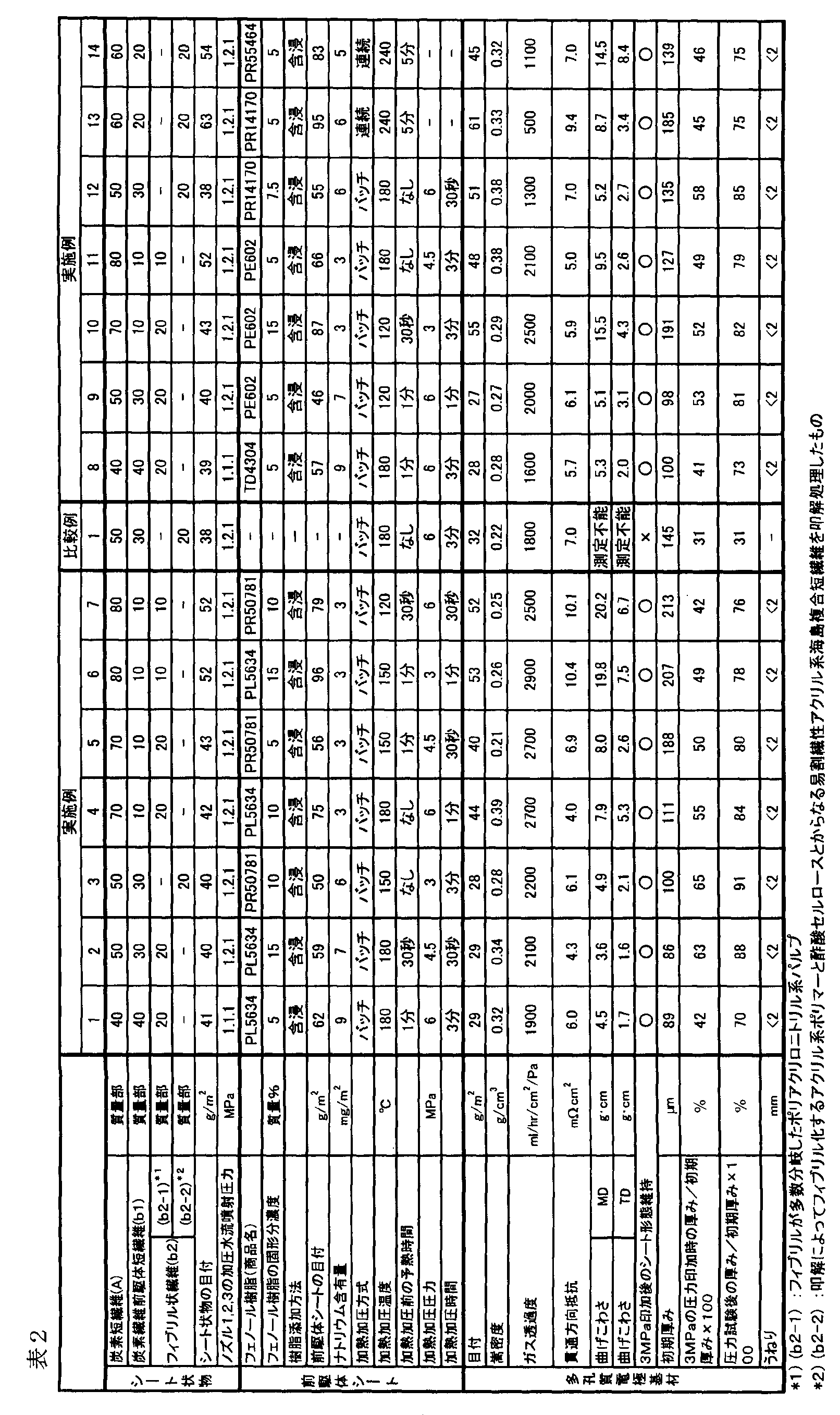
(4)抄紙用スラリーの調製、(5)シート状物の製造および加圧水流噴射による3次元交絡処理、(6)樹脂添加および乾燥処理、および(7)加熱加圧を以下の通り行った以外は実施例1と同様にして、炭素短繊維(A)が繊維状の樹脂炭化物(炭素繊維(B))と不定形な樹脂炭化物(C)とで結着された多孔質炭素電極基材を得た。
炭素短繊維(A)と炭素繊維前駆体短繊維(b1)とフィブリル状繊維(b2)とが、質量比50:30:20となるように、かつスラリー中の繊維(フロック)の濃度が1.4g/Lとなるように、離解スラリー繊維(SA)、離解スラリー繊維(Sb1)、離解スラリー繊維(Sb2)および希釈水を計量し、スラリー供給タンクに投入した。さらに、ポリアクリルアマイドを添加して粘度22mPa・s(センチポイズ)の抄紙用スラリーを調製した。
試験機のネット上に上記抄紙用スラリーを定量ポンプによりネット上に供給した。抄紙用スラリーは均一な流れに整流するためのフローボックスを通して所定サイズに拡幅して供給した。その後静置、自然脱水する部分を通過して、減圧脱水装置により完全脱水し、目標目付40g/m2の湿紙ウエッブをネット上に積載した(工程[1]及び工程[7])。この処理が完了すると同時に、試験機後方のウォータージェットノズルより、加圧水流噴射圧力を1MPa(ノズル1)、圧力2MPa(ノズル2)、圧力1MPa(ノズル3)の順で通過させて交絡処理を加えることにより(工程[4])、水分を含んだ交絡構造シートを得た。この水分を含んだ交絡構造シートを乾燥した後の目付は42g/m2であり、乾燥後のシートを100質量部とすると494質量部の水分を含んでいた。このシート中での炭素繊維前駆体短繊維(b1)およびフィブリル状繊維(b2)の分散状態は良好であった。
水分散性フェノール樹脂であるレゾール型フェノール樹脂の水分散液(住友ベークライト(株)製、商品名:PR-55464)を用意し、樹脂固形分が10質量%となるように純水で希釈し、樹脂添加液を調製した。この樹脂添加液を、二重管スプレー方式バルブ(エース技研(株)製、商品名:BP-107DN-SP)を用いて、送液圧0.2MPa、エア圧0.2MPaの圧送方式により、前記水分を含んだ交絡構造シートに噴霧した(工程[2])。次いで、ニップロールを通した後、100℃の熱風乾燥炉で水分を十分に乾燥させ(工程[6])、樹脂の不揮発分を36g/m2付着させた前駆体シートを得た。
前記前駆体シートの両面を、シリコーン系離型剤をコートした紙で挟んだ後、バッチプレス装置にて150℃、予備加熱なし、3MPaで1分間加熱加圧することにより(工程[5])、表面が平滑化された加熱加圧シートを得た。
以下の点以外は、実施例15と同様にして水分を含んだ3次元交絡構造シートを作製した。
・フィブリル状繊維(b2)として、叩解によってフィブリル化するアクリル系ポリマーとジアセテート(酢酸セルロース)とからなる易割繊性アクリル系海島複合短繊維(三菱レイヨン(株)製、商品名:ボンネルM.V.P.-C651、平均繊維長:3mm)を叩解処理したもの(繊維(b2-2))を用いた点。
なお、叩解処理は、前記易割繊性アクリル系海島複合短繊維を、繊維濃度が0.2%(2g/L)になるように水中へ分散して、ディスクリファイナー(熊谷理機製)を通すことによって、濾水度350~400mL程度の繊維(b2-2)が得られるようにした。
・抄紙用スラリーを調製する際に、炭素短繊維(A)と炭素繊維前駆体短繊維(b1)とフィブリル状維(b2)との質量比を60:20:20となるようにした点。
・樹脂添加液に用いる樹脂水分散液としてレゾール型フェノール樹脂の水分散液(住友ベークライト(株)製、商品名:PR-14170)を使用した点。
・樹脂添加方法として、渦流式微粒化ノズル((株)アトマックス製、商品名:AM45)を用いて、エア圧0.2MPaの液剤吸上げ方式により、水分を含んだ交絡構造シートに樹脂を噴霧する方法を用いた点。
・加熱加圧の際の温度を180℃、圧力を4.5MPaとした点。
抄紙用スラリーを調製する際に、炭素短繊維(A)と、炭素繊維前駆体短繊維(b1)と、フィブリル状繊維(b2)とが、質量比80:10:10となるようにした以外は、実施例15と同様にして水分を含んだ3次元交絡構造シートを作製した。
・樹脂添加液に用いる樹脂水分散液の代わりに、水溶性フェノール樹脂であるレゾール型フェノール樹脂の水溶液(住友ベークライト(株)製、商品名:PR-50781)を使用した点。
・樹脂添加方法として、二重管スプレー方式バルブ(エース技研(株)製、商品名:BP-107DN-SP)を用いて、送液圧0.2MPa、エア圧0MPaの点滴方式により、水分を含んだ3次元交絡構造シートに樹脂を滴下する方法を用いた点。
・樹脂を添加した後の水分を含んだ交絡構造シートをニップロールに通した後、水分を乾燥しなかった(工程[6]を行わなかった)点。
・加熱加圧の際の温度を200℃、圧力を6MPaとした点。
実施例15と同様にして水分を含んだ3次元交絡構造シートを得た。次いで、以下の点以外は実施例15と同様にして、得られた交絡構造シートから多孔質電極基材を作製した。
・樹脂添加液に用いる樹脂水分散液としてレゾール型フェノール樹脂の水分散液(住友ベークライト(株)製、商品名:PR-14170)を使用し、樹脂添加液中の樹脂固形分濃度を15質量%にした点。
・樹脂添加方法として、二重管スプレー方式バルブ(エース技研(株)製、商品名:BP-107DN-SP)を用いて、送液圧0.2MPa、エア圧0MPaの点滴方式により、水分を含んだ3次元交絡構造シートに樹脂を滴下する方法を用いた点。
・樹脂を添加した後の水分を含んだ交絡構造シートをニップロールに通した後、水分を乾燥しなかった点。
・加熱加圧の際の温度を180℃、圧力を6MPaとした点。
実施例16と同様にして水分を含んだ3次元交絡構造シートを得た。次いで、以下の点以外は実施例15と同様にして、得られた交絡構造シートから多孔質電極基材を作製した。
・樹脂添加液に用いる樹脂水分散液の代わりに、レゾール型フェノール樹脂の水溶液(住友ベークライト(株)製、商品名:PR-50781)を使用し、樹脂添加液中の樹脂固形分濃度を15質量%にした点。
・前駆体シートの加熱加圧の温度を200℃とした点。
実施例17と同様にして水分を含んだ3次元交絡構造シートを得た。次に、以下の点以外は実施例15と同様にして、得られた交絡構造シートから多孔質電極基材を作製した。
・樹脂添加液中の樹脂固形分濃度を15質量%にした点。
・樹脂添加方法として、渦流式微粒化ノズル((株)アトマックス製、商品名:AM45)を用いて、エア圧0.2MPaの液剤吸上げ方式により、水分を含んだ3次元交絡構造シートに樹脂を噴霧する方法を用いた点。
・樹脂を添加した後の水分を含んだ交絡構造シートをニップロールに通した後、水分を乾燥しなかった点。
・加熱加圧の際の圧力を4.5MPaとした点。
実施例15と同様にして水分を含んだ3次元交絡構造シートを得た。次いで、以下の点以外は実施例15と同様にして、得られた交絡構造シートから多孔質電極基材を作製した。
・この水分を含んだ3次元交絡構造シートをピンテンター試験機(辻井染色機製、商品名:PT-2A-400)により150℃×3分で乾燥させることで、乾燥した交絡構造シートを得た(交絡処理工程[4]と樹脂添加工程[2]との間に乾燥処理工程[7]を含む)点。
・樹脂添加液に用いる樹脂水分散液の代わりに、レゾール型フェノール樹脂の水溶液(住友ベークライト(株)製、商品名:PR-50781)を使用した点。
・樹脂添加方法として、二重管スプレー方式バルブ(エース技研(株)製、商品名:BP-107DN-SP)を用いて、送液圧0.2MPa、エア圧0MPaの点滴方式により、乾燥させた3次元交絡構造シートに樹脂を滴下する方法を用いた点。
・前駆体シートの加熱加圧の圧力を4.5MPaとした点。
実施例16と同様にして水分を含んだ3次元交絡構造シートを得た。次いで、以下の点以外は実施例15と同様にして、得られた交絡構造シートから多孔質電極基材を作製した。
・この水分を含んだ3次元交絡構造シートをピンテンター試験機(辻井染色機製、商品名:PT-2A-400)により150℃×3分で乾燥させることで、乾燥した3次元交絡構造シートを得た点。
・前駆体シートの加熱加圧の温度を180℃、圧力を6MPaとした点。
実施例17と同様にして水分を含んだ3次元交絡構造シートを得た。次いで、以下の点以外は実施例15と同様にして、得られた交絡構造シートから多孔質電極基材を作製した。
・この水分を含んだ3次元交絡構造シートをピンテンター試験機(辻井染色機製、商品名:PT-2A-400)により150℃×3分で乾燥させることで、乾燥した3次元交絡構造シートを得た点。
・樹脂添加液に用いる樹脂水分散液として、レゾール型フェノール樹脂の水分散液(住友ベークライト(株)製、商品名:PR-14170)を使用した点。
・樹脂添加方法として、渦流式微粒化ノズル((株)アトマックス製、商品名:AM45)を用いて、エア圧0.2MPaの液剤吸上げ方式により、乾燥した3次元交絡構造シートに樹脂を噴霧する方法を用いた点。
・樹脂を添加した後の3次元交絡構造シートをニップロールに通した後、水分を乾燥しなかった点。
・加熱加圧処理の際の温度を200℃とした点。
(1)膜-電極接合体(MEA)の製造
実施例6で得られた多孔質電極基材2組を、カソード用およびアノード用の多孔質電極基材として用意した。また、パーフルオロスルホン酸系の高分子電解質膜(膜厚:30μm)の両面に触媒担持カーボン(触媒:Pt、触媒担持量:50質量%)からなる触媒層(触媒層面積:25cm2、Pt付着量:0.3mg/cm2)を形成した積層体を容易した。この積層体を、カソード用およびアノード用の多孔質電極基材で挟持し、これらを接合して、MEAを得た。
得られたMEAを、蛇腹状のガス流路を有する2枚のカーボンセパレーターによって挟み、固体高分子型燃料電池(単セル)を形成した。この単セルの電流密度-電圧特性を測定することによって、燃料電池特性評価を行った。燃料ガスとしては水素ガスを用い、酸化ガスとしては空気を用いた。単セルの温度を80℃、燃料ガス利用率を60%、酸化ガス利用率を40%とした。また、燃料ガスと酸化ガスへの加湿は80℃のバブラーにそれぞれ燃料ガスと酸化ガスを通すことによって行った。その結果、電流密度が0.8A/cm2のときの燃料電池セルのセル電圧が0.600V、セルの内部抵抗が4.8mΩであり、良好な特性を示した。
実施例14で得られた多孔質電極基材を用いた以外は実施例24と同様にして膜-電極接合体(MEA)を作製し、MEAの燃料電池特性評価を行った。その結果、電流密度が0.8A/cm2のときの燃料電池セルのセル電圧が0.612V、セルの内部抵抗が4.5mΩであり、良好な特性を示した。
実施例18で得られた多孔質電極基材を用いた以外は実施例24と同様にして膜-電極接合体(MEA)を作製し、MEAの燃料電池特性評価を行った。その結果、電流密度が0.8A/cm2のときの燃料電池セルのセル電圧が0.627V、セルの内部抵抗が3.3mΩであり、良好な特性を示した。
以下の点以外は、実施例23と同様にして多孔質電極基材を得た。
・炭素繊維前駆体短繊維(b1)を使用せず、フィブリル状繊維(b2)として、繊維状の幹より直径が3μm以下のフィブリルが多数分岐した、噴射凝固によって作製したポリアクリロニトリル系パルプ(b2-1)を使用し、この炭素短繊維(A)とフィブリル状繊維(b2-1)とが、質量比80:20となるようにした点。
・抄紙用スラリーから、減圧脱水装置を用いて完全脱水されたシート状物を作製し(工程[1]及び工程[7])、このシート状物に対して、交絡処理を行わずに、そのまま樹脂添加工程[2]を行った点。
・樹脂添加液に用いる樹脂水分散液として、レゾール型フェノール樹脂の水分散液(住友ベークライト(株)製、商品名:PR-55464)を使用し、樹脂添加液中の樹脂固形分濃度を15質量%にした点。
・樹脂添加方法として、二重管スプレー方式バルブ(エース技研(株)製、商品名:BP-107DN-SP)を用いて、送液圧0.2MPa、エア圧0MPaの点滴方式により、前記完全脱水されたシート状物に樹脂を滴下する方法を用いた点。
・送風乾燥機を用いて80℃で、樹脂を添加したシート状物(前駆体シート)中の水を十分に乾燥させた点。
・加熱加圧の際の温度を180℃、時間を3分とした点。
以下の点以外は、実施例27と同様にして多孔質電極基材を得た。
・上記完全脱水されたシート状物に対して、実施例23に示すように交絡処理を行い、その際の加圧水流噴射圧力を2MPa(ノズル1)、圧力2MPa(ノズル2)、圧力2MPa(ノズル3)にした点。
・樹脂添加方法として、渦流式微粒化ノズル((株)アトマックス製、商品名:AM45)を用いて、エア圧0.2MPaの液剤吸上げ方式により、3次元交絡構造シートに樹脂を噴霧する方法を用いた点。
(実施例29)
以下の点以外は、実施例8と同様にして多孔質電極基材を得た。
・シート状物の交絡処理を行わず、減圧脱水装置により完全脱水したシート状物に対して、樹脂添加工程[2]を行った点。
・樹脂添加液に用いる樹脂水分散液として、レゾール型フェノール樹脂の水分散液(住友ベークライト(株)製、商品名:PR-55464)を使用し、樹脂添加液中の樹脂固形分濃度を15質量%にした点。
・樹脂添加方法として、二重管スプレー方式バルブ(エース技研(株)製、商品名:BP-107DN-SP)を用いて、送液圧0.2MPa、エア圧0MPaの点滴方式により、完全脱水したシート状物に樹脂を滴下する方法を用いた点。

B :炭素繊維(B)
C :樹脂炭化物(C)
1 :シート面と平行な線
Claims (19)
- 以下の[1]~[3]の工程を含む、多孔質電極基材の製造方法:
[1]炭素短繊維(A)が分散したシート状物を製造する工程、
[2]該シート状物に、水溶性フェノール樹脂および水分散性フェノール樹脂のうちの一方または両方を添加して、前駆体シートを製造する工程、
[3]該前駆体シートを1000℃以上の温度で炭素化処理する工程。 - 前記工程[1]と前記工程[2]の間に、前記シート状物を交絡処理する工程[4]を含む、請求項1に記載の製造方法。
- 前記工程[1]と前記工程[2]の間に、シート状物を乾燥処理する工程[7]を含む、請求項1に記載の製造方法。
- 前記工程[1]と前記工程[4]の間、および、前記工程[4]と前記工程[2]の間、のうちの一方または両方に、シート状物を乾燥処理する工程[7]を含む、請求項2に記載の製造方法。
- 前記工程[1]が、炭素短繊維(A)と、炭素繊維前駆体短繊維(b1)およびフィブリル状繊維(b2)のうちの一方または両方とが分散したシート状物を製造する工程である、請求項1~4のいずれか1項に記載の製造方法。
- 前記工程[2]と前記工程[3]の間に、前記前駆体シートを100℃以上250℃以下の温度で加熱加圧する工程[5]を含む、請求項1~5のいずれか1項に記載の製造方法。
- 前記工程[2]と前記工程[5]の間に、前記前駆体シートを乾燥処理する工程[6]を含む、請求項6に記載の製造方法。
- 前記工程[1]より得られるシート状物が、水溶性バインダーを含有し、該工程[1]より得られるシート状物中の水溶性バインダーの含有量が10g/m2以下である、請求項1~7のいずれか1項に記載の製造方法。
- 前記工程[2]が、該工程[2]に供給するシート状物に、水溶性フェノール樹脂および水分散性フェノール樹脂のうちの一方または両方の樹脂を噴霧、滴下または流下することによって添加して、前駆体シートを製造する工程である、請求項1~8のいずれか1項に記載の製造方法。
- 請求項1~9のいずれか1項に記載の方法で製造される多孔質電極基材。
- 炭素短繊維(A)が、水溶性フェノール樹脂および水分散性フェノール樹脂のうちの一方または両方由来の樹脂炭化物(C)により接合された構造を有する多孔質電極基材。
- 炭素短繊維(A)が、炭素繊維前駆体短繊維(b1)およびフィブリル状繊維(b2)のうちの一方または両方由来の炭素繊維(B)と、水溶性フェノール樹脂および水分散性フェノール樹脂のうちの一方または両方由来の樹脂炭化物(C)とにより接合された構造を有する多孔質電極基材であって、
該多孔質電極基材中で該炭素短繊維(A)が3次元交絡構造を形成している多孔質電極基材。 - 炭素短繊維(A)が炭化物により結合された構造を有する多孔質電極基材であって、
嵩密度が0.20g/cm3以上0.45g/cm3以下であり、かつ、
3MPaの圧力印加時の厚みが、0.05MPaの圧力印加時の厚みの30%以上70%以下である、多孔質電極基材。 - 炭素短繊維(A)が炭化物により結合された構造を有する多孔質電極基材であって、
嵩密度が0.20g/cm3以上0.45g/cm3以下であり、かつ、
3MPaの圧力印加時の厚みが、0.05MPaの圧力印加時の厚みである初期厚みの30%以上70%以下であり、かつ、
該3MPaの圧力印加後、0.05MPaまで除圧した際の厚みが該初期厚みの60%以上98%以下である、多孔質電極基材。 - 嵩密度が0.20g/cm3以上0.45g/cm3以下であり、かつ、
3MPaの圧力印加時の厚みが、0.05MPaの圧力印加時の厚みの30%以上70%以下である、請求項12に記載の多孔質電極基材。 - 嵩密度が0.20g/cm3以上0.45g/cm3以下であり、かつ、
3MPaの圧力印加時の厚みが、0.05MPaの圧力印加時の厚みである初期厚みの30%以上70%以下であり、かつ、
該3MPaの圧力印加後、0.05MPaまで除圧した際の厚みが該初期厚みの60%以上98%以下である、請求項12に記載の多孔質電極基材。 - 炭素短繊維(A)と、フェノール樹脂とを含む多孔質電極基材用の前駆体シートであって、ナトリウムの含有量が150mg/m2以下である前駆体シート。
- 請求項10~16のいずれか1項に記載の多孔質電極基材を含む膜-電極接合体。
- 請求項18記載の膜-電極接合体を含む固体高分子型燃料電池。
Priority Applications (7)
| Application Number | Priority Date | Filing Date | Title |
|---|---|---|---|
| EP12739680.2A EP2669977A4 (en) | 2011-01-27 | 2012-01-20 | POROUS ELECTRODE SUBSTRATE, MANUFACTURING METHOD, PRECURSOR FILM, MEMBRANE ELECTRODE ASSEMBLY AND FESTPOLYMER FUEL CELL |
| US13/982,061 US9705137B2 (en) | 2011-01-27 | 2012-01-20 | Porous electrode substrate, method for manufacturing same, precursor sheet, membrane electrode assembly, and polymer electrolyte fuel cell |
| KR1020137018908A KR101571227B1 (ko) | 2011-01-27 | 2012-01-20 | 다공질 전극 기재, 그의 제조 방법, 전구체 시트, 막-전극 접합체 및 고체 고분자형 연료 전지 |
| CA2825663A CA2825663C (en) | 2011-01-27 | 2012-01-20 | Porous electrode substrate, method for manufacturing same, precursor sheet, membrane electrode assembly, and polymer electrolyte fuel cell |
| JP2012504215A JP5458168B2 (ja) | 2011-01-27 | 2012-01-20 | 多孔質電極基材の製造方法 |
| CN201280006456.8A CN103329323B (zh) | 2011-01-27 | 2012-01-20 | 多孔电极基材、其制造方法、前体片材、膜-电极接合体及固体高分子型燃料电池 |
| US15/077,613 US9825304B2 (en) | 2011-01-27 | 2016-03-22 | Porous electrode substrate, method for manufacturing same, precursor sheet, membrane electrode assembly, and polymer electrolyte fuel cell |
Applications Claiming Priority (6)
| Application Number | Priority Date | Filing Date | Title |
|---|---|---|---|
| JP2011-015639 | 2011-01-27 | ||
| JP2011015638 | 2011-01-27 | ||
| JP2011015639 | 2011-01-27 | ||
| JP2011-066344 | 2011-03-24 | ||
| JP2011066344 | 2011-03-24 | ||
| JP2011-015638 | 2011-07-08 |
Related Child Applications (2)
| Application Number | Title | Priority Date | Filing Date |
|---|---|---|---|
| US13/982,061 A-371-Of-International US9705137B2 (en) | 2011-01-27 | 2012-01-20 | Porous electrode substrate, method for manufacturing same, precursor sheet, membrane electrode assembly, and polymer electrolyte fuel cell |
| US15/077,613 Division US9825304B2 (en) | 2011-01-27 | 2016-03-22 | Porous electrode substrate, method for manufacturing same, precursor sheet, membrane electrode assembly, and polymer electrolyte fuel cell |
Publications (1)
| Publication Number | Publication Date |
|---|---|
| WO2012102195A1 true WO2012102195A1 (ja) | 2012-08-02 |
Family
ID=46580764
Family Applications (1)
| Application Number | Title | Priority Date | Filing Date |
|---|---|---|---|
| PCT/JP2012/051177 Ceased WO2012102195A1 (ja) | 2011-01-27 | 2012-01-20 | 多孔質電極基材、その製造方法、前駆体シート、膜-電極接合体及び固体高分子型燃料電池 |
Country Status (8)
| Country | Link |
|---|---|
| US (2) | US9705137B2 (ja) |
| EP (1) | EP2669977A4 (ja) |
| JP (3) | JP5458168B2 (ja) |
| KR (1) | KR101571227B1 (ja) |
| CN (1) | CN103329323B (ja) |
| CA (1) | CA2825663C (ja) |
| TW (1) | TWI513087B (ja) |
| WO (1) | WO2012102195A1 (ja) |
Cited By (4)
| Publication number | Priority date | Publication date | Assignee | Title |
|---|---|---|---|---|
| WO2013147174A1 (ja) * | 2012-03-30 | 2013-10-03 | 三菱レイヨン株式会社 | 多孔質電極基材、その製造方法及び前駆体シート |
| JP2016000885A (ja) * | 2014-05-23 | 2016-01-07 | 東レ株式会社 | 炭素繊維不織布、固体高分子形燃料電池用ガス拡散電極および固体高分子形燃料電池 |
| US9705137B2 (en) | 2011-01-27 | 2017-07-11 | Mitsubishi Rayon Co., Ltd. | Porous electrode substrate, method for manufacturing same, precursor sheet, membrane electrode assembly, and polymer electrolyte fuel cell |
| JP2021008369A (ja) * | 2019-06-28 | 2021-01-28 | 旭化成株式会社 | 炭素フォーム |
Families Citing this family (12)
| Publication number | Priority date | Publication date | Assignee | Title |
|---|---|---|---|---|
| US9325016B2 (en) | 2010-11-01 | 2016-04-26 | Mitsubishi Rayon Co., Ltd. | Porous electrode substrate and process for production thereof, porous electrode substrate precursor sheet, membrane-electrode assembly, and polymer electrolyte fuel cell |
| US9551092B2 (en) * | 2014-07-29 | 2017-01-24 | American Felt & Filter Company | Multi-fiber carding apparatus and method |
| EP3217456B1 (en) * | 2014-11-04 | 2020-05-06 | Mitsubishi Chemical Corporation | Porous electrode substrate, membrane/electrode assembly using same, and solid polymer fuel cell using same |
| JP6477401B2 (ja) * | 2014-11-04 | 2019-03-06 | 三菱ケミカル株式会社 | 多孔質電極基材およびそれを用いた膜−電極接合体並びにそれを用いた固体高分子型燃料電池 |
| JP6729373B2 (ja) * | 2015-03-25 | 2020-07-22 | 東レ株式会社 | 多孔質炭素電極基材、その製造方法、ガス拡散層、および燃料電池用膜−電極接合体 |
| US20180108920A1 (en) * | 2015-04-02 | 2018-04-19 | Mitsubishi Chemical Corporation | Porous electrode substrate and manufacturing method therefor |
| KR101755920B1 (ko) * | 2015-12-08 | 2017-07-07 | 현대자동차주식회사 | 연료전지용 기체확산층과, 이를 제조하기 위한 장치 및 방법 |
| JP6743805B2 (ja) * | 2015-12-11 | 2020-08-19 | 東レ株式会社 | 炭素シート、ガス拡散電極基材、および燃料電池 |
| KR102234017B1 (ko) * | 2016-12-29 | 2021-03-29 | 코오롱인더스트리 주식회사 | 펴짐성이 우수한 롤 타입 가스확산층의 제조방법 |
| JP7302474B2 (ja) | 2018-09-28 | 2023-07-04 | 東レ株式会社 | ガス拡散層、膜電極接合体および燃料電池 |
| CN109305815A (zh) * | 2018-12-12 | 2019-02-05 | 雅安远创陶瓷有限责任公司 | 一种高强度多孔陶瓷及其制备工艺 |
| CN110174704B (zh) * | 2019-06-24 | 2023-06-16 | 青岛科技大学 | 一种基于triz理念的海洋电场传感器 |
Citations (17)
| Publication number | Priority date | Publication date | Assignee | Title |
|---|---|---|---|---|
| JPS6059660A (ja) * | 1983-09-12 | 1985-04-06 | Hitachi Ltd | 燃料電池用多孔質電極板の製造方法 |
| JPS62154470A (ja) * | 1985-12-25 | 1987-07-09 | Tokai Carbon Co Ltd | 燃料電池用炭素質部材の製造方法 |
| JPH01253164A (ja) * | 1988-02-12 | 1989-10-09 | Internatl Fuel Cells Corp | 腐食に対し耐性を有する燃料電池基盤及びその製造方法 |
| JPH1143890A (ja) * | 1996-12-26 | 1999-02-16 | Mitsubishi Paper Mills Ltd | 不織布、電池用セパレータおよび電池 |
| JP2003286085A (ja) * | 2002-03-27 | 2003-10-07 | Toray Ind Inc | 多孔質炭素板およびその製造方法 |
| JP2004100102A (ja) * | 2002-09-10 | 2004-04-02 | Mitsubishi Chemicals Corp | 炭素質繊維織布 |
| JP2004307815A (ja) | 2003-03-24 | 2004-11-04 | Sumitomo Bakelite Co Ltd | 抄紙用レゾール型フェノール樹脂乳濁液及びその製造方法 |
| JP3699447B2 (ja) | 2000-07-14 | 2005-09-28 | 三菱レイヨン株式会社 | 炭素系材料シートの製造方法 |
| JP2005299069A (ja) * | 2004-03-16 | 2005-10-27 | Toray Ind Inc | 合成紙およびその製造方法 |
| JP2006056960A (ja) | 2004-08-19 | 2006-03-02 | Sumitomo Bakelite Co Ltd | レゾール型フェノール樹脂乳濁液及びその製造方法 |
| JP2007115574A (ja) * | 2005-10-21 | 2007-05-10 | Aisin Chem Co Ltd | 燃料電池電極用ガス拡散層及びその製造方法 |
| JP2007173009A (ja) * | 2005-12-21 | 2007-07-05 | Nissan Motor Co Ltd | 膜電極接合体の製造方法 |
| JP2007244997A (ja) | 2006-03-16 | 2007-09-27 | Atomakkusu:Kk | 液体送給菅嵌入型渦流式微粒化ノズル |
| JP2007273466A (ja) | 2006-03-20 | 2007-10-18 | Gm Global Technology Operations Inc | 燃料電池用ガス拡散媒体としてのアクリル繊維結合炭素繊維紙 |
| JP2009084382A (ja) | 2007-09-28 | 2009-04-23 | Sumitomo Bakelite Co Ltd | レゾール型フェノール樹脂の製造方法 |
| JP2009283259A (ja) * | 2008-05-21 | 2009-12-03 | Mitsubishi Rayon Co Ltd | 多孔質炭素電極基材 |
| WO2011004853A1 (ja) * | 2009-07-08 | 2011-01-13 | 三菱レイヨン株式会社 | 多孔質電極基材及びその製造方法 |
Family Cites Families (40)
| Publication number | Priority date | Publication date | Assignee | Title |
|---|---|---|---|---|
| JPS6059660B2 (ja) | 1980-12-09 | 1985-12-26 | 富士通株式会社 | 磁気ディスク記憶装置 |
| JPS60122711A (ja) | 1983-12-08 | 1985-07-01 | Oji Paper Co Ltd | 多孔質炭素板の製造方法 |
| US4985316A (en) | 1988-02-12 | 1991-01-15 | International Fuel Cells Corporation | Corrosion resistant fuel cell substrates |
| US5026402A (en) | 1989-11-03 | 1991-06-25 | International Fuel Cells Corporation | Method of making a final cell electrode assembly substrate |
| JP2565024B2 (ja) * | 1991-07-18 | 1996-12-18 | 住友金属工業株式会社 | 半導体治具用炭化珪素粉末の製造方法 |
| EP1139471A4 (en) | 1999-09-22 | 2002-09-04 | Toray Industries | POROUS, ELECTRICALLY CONDUCTIVE SHEET AND METHOD FOR THE PRODUCTION THEREOF |
| WO2001056103A1 (en) | 2000-01-27 | 2001-08-02 | Mitsubishi Rayon Co., Ltd. | Porous carbon electrode material, method for manufacturing the same, and carbon fiber paper |
| JP2001240477A (ja) | 2000-02-28 | 2001-09-04 | Mitsubishi Rayon Co Ltd | 炭素質多孔質体とその製造方法 |
| KR100661785B1 (ko) | 2000-11-24 | 2006-12-28 | 도호 테낙구스 가부시키가이샤 | 탄소섬유 시트 및 이의 제조 방법 |
| JP4329296B2 (ja) | 2001-02-28 | 2009-09-09 | 三菱化学株式会社 | 導電性炭素質繊維シート及び固体高分子型燃料電池 |
| JP2002266217A (ja) | 2001-03-08 | 2002-09-18 | Mitsubishi Rayon Co Ltd | 炭素繊維不織布およびその製造方法 |
| JP2003151568A (ja) | 2001-11-09 | 2003-05-23 | Mitsubishi Rayon Co Ltd | 固体高分子型燃料電池用の電極基材とその製造方法 |
| JP2003213563A (ja) | 2002-01-21 | 2003-07-30 | Toho Tenax Co Ltd | 親水性炭素繊維シート状物、炭素繊維電極材料およびその製造方法 |
| US7144476B2 (en) * | 2002-04-12 | 2006-12-05 | Sgl Carbon Ag | Carbon fiber electrode substrate for electrochemical cells |
| KR100594535B1 (ko) * | 2002-04-17 | 2006-06-30 | 미쯔비시 레이온 가부시끼가이샤 | 탄소 섬유지 및 그것을 이용한 연료 전지용 다공질 탄소전극 기재 |
| JP2004134108A (ja) | 2002-10-08 | 2004-04-30 | Mitsubishi Rayon Co Ltd | 多孔質炭素電極基材前駆体シート状物の製造方法 |
| JP4850257B2 (ja) * | 2002-10-08 | 2012-01-11 | 三菱化学エンジニアリング株式会社 | 加圧水蒸気噴出ノズルを用いた不織布の製造装置 |
| JP4461695B2 (ja) | 2003-03-24 | 2010-05-12 | 東レ株式会社 | 多孔質炭素電極基材およびその製造方法 |
| JP4389535B2 (ja) | 2003-09-26 | 2009-12-24 | 東レ株式会社 | 多孔質炭素基材ならびに該基材を用いてなるガス拡散体、膜−電極接合体および燃料電池 |
| JP2004296176A (ja) | 2003-03-26 | 2004-10-21 | Toray Ind Inc | 固体高分子型燃料電池 |
| JP5055682B2 (ja) | 2003-03-27 | 2012-10-24 | 東レ株式会社 | 多孔質炭素板およびその製造方法 |
| JP4338491B2 (ja) | 2003-10-08 | 2009-10-07 | パナソニック株式会社 | 高分子電解質型燃料電池用ガス拡散層の製造方法 |
| JP2005240224A (ja) | 2004-02-26 | 2005-09-08 | Toho Tenax Co Ltd | 高密度耐炎繊維不織布及び炭素繊維不織布、並びにそれらの製造方法 |
| JP2005281871A (ja) | 2004-03-26 | 2005-10-13 | Toho Tenax Co Ltd | 炭素繊維織物及びその製造方法 |
| JP2005317240A (ja) | 2004-04-27 | 2005-11-10 | Toray Ind Inc | 炭素繊維不織布、ガス拡散体、膜−電極接合体および燃料電池 |
| GB0413324D0 (en) | 2004-06-15 | 2004-07-21 | Johnson Matthey Plc | Gas diffusion substrate |
| US20080038589A1 (en) | 2004-06-21 | 2008-02-14 | Mitsubishi Rayon Co., Ltd. | Porous Electrode Base Material and Production Method Thereof |
| JP2006040886A (ja) * | 2004-06-21 | 2006-02-09 | Mitsubishi Rayon Co Ltd | 多孔質電極基材およびその製造方法 |
| CN100527496C (zh) * | 2004-06-21 | 2009-08-12 | 三菱丽阳株式会社 | 多孔质电极基材及其制造方法 |
| JP2006089331A (ja) * | 2004-09-24 | 2006-04-06 | Toray Ind Inc | 炭素繊維基材の製造方法 |
| US8142883B2 (en) * | 2005-09-29 | 2012-03-27 | Takashi Chida | Porous carbon sheet and process for production thereof |
| TWI296449B (en) * | 2006-01-04 | 2008-05-01 | Univ Feng Chia | Porous carbon electrode substrates and methods for preparing the same |
| JP5416990B2 (ja) | 2008-03-05 | 2014-02-12 | 三菱レイヨン株式会社 | 多孔質炭素電極基材、並びにそれを用いた膜−電極接合体及び固体高分子型燃料電池 |
| KR101701529B1 (ko) * | 2009-02-04 | 2017-02-01 | 미츠비시 레이온 가부시키가이샤 | 다공질 전극 기재, 그 제조 방법, 막-전극 접합체, 및 고체 고분자형 연료전지 |
| JP5484777B2 (ja) | 2009-04-24 | 2014-05-07 | 三菱レイヨン株式会社 | 多孔質電極基材およびその製造方法 |
| EP2506353B1 (en) * | 2009-11-24 | 2018-01-17 | Mitsubishi Chemical Corporation | Porous electrode base material, process for production thereof, precursor sheet, film-electrode assembly, and solid polymer fuel cell |
| JP2011151009A (ja) * | 2009-12-22 | 2011-08-04 | Mitsubishi Rayon Co Ltd | 多孔質電極基材の製造方法 |
| JP2011258395A (ja) | 2010-06-09 | 2011-12-22 | Toyota Motor Corp | 燃料電池に用いられるガス拡散層の製造方法、および、製造装置 |
| US9705137B2 (en) | 2011-01-27 | 2017-07-11 | Mitsubishi Rayon Co., Ltd. | Porous electrode substrate, method for manufacturing same, precursor sheet, membrane electrode assembly, and polymer electrolyte fuel cell |
| US9924956B2 (en) | 2011-01-28 | 2018-03-27 | DePuy Synthes Products, Inc. | Alignment device for distal targeting |
-
2012
- 2012-01-20 US US13/982,061 patent/US9705137B2/en not_active Expired - Fee Related
- 2012-01-20 WO PCT/JP2012/051177 patent/WO2012102195A1/ja not_active Ceased
- 2012-01-20 KR KR1020137018908A patent/KR101571227B1/ko not_active Expired - Fee Related
- 2012-01-20 EP EP12739680.2A patent/EP2669977A4/en not_active Withdrawn
- 2012-01-20 CA CA2825663A patent/CA2825663C/en active Active
- 2012-01-20 JP JP2012504215A patent/JP5458168B2/ja not_active Expired - Fee Related
- 2012-01-20 TW TW101102527A patent/TWI513087B/zh active
- 2012-01-20 CN CN201280006456.8A patent/CN103329323B/zh active Active
-
2013
- 2013-10-21 JP JP2013218365A patent/JP5751309B2/ja active Active
-
2015
- 2015-02-02 JP JP2015018392A patent/JP6008000B2/ja active Active
-
2016
- 2016-03-22 US US15/077,613 patent/US9825304B2/en active Active
Patent Citations (17)
| Publication number | Priority date | Publication date | Assignee | Title |
|---|---|---|---|---|
| JPS6059660A (ja) * | 1983-09-12 | 1985-04-06 | Hitachi Ltd | 燃料電池用多孔質電極板の製造方法 |
| JPS62154470A (ja) * | 1985-12-25 | 1987-07-09 | Tokai Carbon Co Ltd | 燃料電池用炭素質部材の製造方法 |
| JPH01253164A (ja) * | 1988-02-12 | 1989-10-09 | Internatl Fuel Cells Corp | 腐食に対し耐性を有する燃料電池基盤及びその製造方法 |
| JPH1143890A (ja) * | 1996-12-26 | 1999-02-16 | Mitsubishi Paper Mills Ltd | 不織布、電池用セパレータおよび電池 |
| JP3699447B2 (ja) | 2000-07-14 | 2005-09-28 | 三菱レイヨン株式会社 | 炭素系材料シートの製造方法 |
| JP2003286085A (ja) * | 2002-03-27 | 2003-10-07 | Toray Ind Inc | 多孔質炭素板およびその製造方法 |
| JP2004100102A (ja) * | 2002-09-10 | 2004-04-02 | Mitsubishi Chemicals Corp | 炭素質繊維織布 |
| JP2004307815A (ja) | 2003-03-24 | 2004-11-04 | Sumitomo Bakelite Co Ltd | 抄紙用レゾール型フェノール樹脂乳濁液及びその製造方法 |
| JP2005299069A (ja) * | 2004-03-16 | 2005-10-27 | Toray Ind Inc | 合成紙およびその製造方法 |
| JP2006056960A (ja) | 2004-08-19 | 2006-03-02 | Sumitomo Bakelite Co Ltd | レゾール型フェノール樹脂乳濁液及びその製造方法 |
| JP2007115574A (ja) * | 2005-10-21 | 2007-05-10 | Aisin Chem Co Ltd | 燃料電池電極用ガス拡散層及びその製造方法 |
| JP2007173009A (ja) * | 2005-12-21 | 2007-07-05 | Nissan Motor Co Ltd | 膜電極接合体の製造方法 |
| JP2007244997A (ja) | 2006-03-16 | 2007-09-27 | Atomakkusu:Kk | 液体送給菅嵌入型渦流式微粒化ノズル |
| JP2007273466A (ja) | 2006-03-20 | 2007-10-18 | Gm Global Technology Operations Inc | 燃料電池用ガス拡散媒体としてのアクリル繊維結合炭素繊維紙 |
| JP2009084382A (ja) | 2007-09-28 | 2009-04-23 | Sumitomo Bakelite Co Ltd | レゾール型フェノール樹脂の製造方法 |
| JP2009283259A (ja) * | 2008-05-21 | 2009-12-03 | Mitsubishi Rayon Co Ltd | 多孔質炭素電極基材 |
| WO2011004853A1 (ja) * | 2009-07-08 | 2011-01-13 | 三菱レイヨン株式会社 | 多孔質電極基材及びその製造方法 |
Non-Patent Citations (1)
| Title |
|---|
| See also references of EP2669977A1 |
Cited By (8)
| Publication number | Priority date | Publication date | Assignee | Title |
|---|---|---|---|---|
| US9705137B2 (en) | 2011-01-27 | 2017-07-11 | Mitsubishi Rayon Co., Ltd. | Porous electrode substrate, method for manufacturing same, precursor sheet, membrane electrode assembly, and polymer electrolyte fuel cell |
| US9825304B2 (en) | 2011-01-27 | 2017-11-21 | Mitsubishi Chemical Corporation | Porous electrode substrate, method for manufacturing same, precursor sheet, membrane electrode assembly, and polymer electrolyte fuel cell |
| WO2013147174A1 (ja) * | 2012-03-30 | 2013-10-03 | 三菱レイヨン株式会社 | 多孔質電極基材、その製造方法及び前駆体シート |
| JPWO2013147174A1 (ja) * | 2012-03-30 | 2015-12-14 | 三菱レイヨン株式会社 | 多孔質電極基材、その製造方法及び前駆体シート |
| US9716278B2 (en) | 2012-03-30 | 2017-07-25 | Mitsubishi Chemical Corporation | Porous electrode base material, method for manufacturing same, and precursor sheet |
| JP2016000885A (ja) * | 2014-05-23 | 2016-01-07 | 東レ株式会社 | 炭素繊維不織布、固体高分子形燃料電池用ガス拡散電極および固体高分子形燃料電池 |
| JP2021008369A (ja) * | 2019-06-28 | 2021-01-28 | 旭化成株式会社 | 炭素フォーム |
| JP7372060B2 (ja) | 2019-06-28 | 2023-10-31 | 旭化成株式会社 | 炭素フォーム |
Also Published As
| Publication number | Publication date |
|---|---|
| CA2825663C (en) | 2023-03-21 |
| US9705137B2 (en) | 2017-07-11 |
| US20130323620A1 (en) | 2013-12-05 |
| TW201244236A (en) | 2012-11-01 |
| JP5458168B2 (ja) | 2014-04-02 |
| CN103329323A (zh) | 2013-09-25 |
| KR20130108647A (ko) | 2013-10-04 |
| EP2669977A4 (en) | 2016-06-22 |
| JP2015118944A (ja) | 2015-06-25 |
| CN103329323B (zh) | 2018-04-27 |
| US20160204443A1 (en) | 2016-07-14 |
| KR101571227B1 (ko) | 2015-11-23 |
| JP2014029873A (ja) | 2014-02-13 |
| TWI513087B (zh) | 2015-12-11 |
| EP2669977A1 (en) | 2013-12-04 |
| JP5751309B2 (ja) | 2015-07-22 |
| CA2825663A1 (en) | 2012-08-02 |
| JPWO2012102195A1 (ja) | 2014-06-30 |
| US9825304B2 (en) | 2017-11-21 |
| JP6008000B2 (ja) | 2016-10-19 |
Similar Documents
| Publication | Publication Date | Title |
|---|---|---|
| JP6008000B2 (ja) | 前駆体シート | |
| JP6086096B2 (ja) | 多孔質電極基材 | |
| JP5356540B2 (ja) | 多孔質電極基材、その製造方法、多孔質電極基材前駆体シート、膜−電極接合体、および固体高分子型燃料電池 | |
| WO2011065327A1 (ja) | 多孔質電極基材、その製法、前駆体シート、膜-電極接合体、および固体高分子型燃料電池 | |
| CN105229833A (zh) | 多孔电极基材、其制造方法以及固体高分子型燃料电池 | |
| JP6288263B2 (ja) | 多孔質電極基材、膜−電極接合体及び固体高分子型燃料電池 | |
| JP5394469B2 (ja) | 多孔質電極基材の製造方法及び多孔質電極基材 | |
| JP5532334B2 (ja) | 多孔質電極基材及びその製造方法 | |
| JP2016012474A (ja) | 多孔質電極基材の製造方法 | |
| JP5501332B2 (ja) | 多孔質電極基材前駆体シート、その製造方法、多孔質電極基材、膜−電極接合体、および固体高分子型燃料電池 | |
| JP2013251070A (ja) | 多孔質電極基材、その製造方法 | |
| JP2018055969A (ja) | 多孔質電極基材およびその製造方法 |
Legal Events
| Date | Code | Title | Description |
|---|---|---|---|
| WWE | Wipo information: entry into national phase |
Ref document number: 2012504215 Country of ref document: JP |
|
| 121 | Ep: the epo has been informed by wipo that ep was designated in this application |
Ref document number: 12739680 Country of ref document: EP Kind code of ref document: A1 |
|
| ENP | Entry into the national phase |
Ref document number: 20137018908 Country of ref document: KR Kind code of ref document: A |
|
| ENP | Entry into the national phase |
Ref document number: 2825663 Country of ref document: CA |
|
| WWE | Wipo information: entry into national phase |
Ref document number: 13982061 Country of ref document: US |
|
| NENP | Non-entry into the national phase |
Ref country code: DE |
|
| WWE | Wipo information: entry into national phase |
Ref document number: 2012739680 Country of ref document: EP |