WO2012102379A1 - Ruban en alliage magnétique doux à base de fe traité par trempe rapide, procédé de fabrication du ruban en alliage, et noyau de fer - Google Patents
Ruban en alliage magnétique doux à base de fe traité par trempe rapide, procédé de fabrication du ruban en alliage, et noyau de fer Download PDFInfo
- Publication number
- WO2012102379A1 WO2012102379A1 PCT/JP2012/051808 JP2012051808W WO2012102379A1 WO 2012102379 A1 WO2012102379 A1 WO 2012102379A1 JP 2012051808 W JP2012051808 W JP 2012051808W WO 2012102379 A1 WO2012102379 A1 WO 2012102379A1
- Authority
- WO
- WIPO (PCT)
- Prior art keywords
- alloy ribbon
- ribbon
- soft magnetic
- based soft
- molten metal
- Prior art date
- Legal status (The legal status is an assumption and is not a legal conclusion. Google has not performed a legal analysis and makes no representation as to the accuracy of the status listed.)
- Ceased
Links
Images



Classifications
-
- H—ELECTRICITY
- H01—ELECTRIC ELEMENTS
- H01F—MAGNETS; INDUCTANCES; TRANSFORMERS; SELECTION OF MATERIALS FOR THEIR MAGNETIC PROPERTIES
- H01F41/00—Apparatus or processes specially adapted for manufacturing or assembling magnets, inductances or transformers; Apparatus or processes specially adapted for manufacturing materials characterised by their magnetic properties
- H01F41/02—Apparatus or processes specially adapted for manufacturing or assembling magnets, inductances or transformers; Apparatus or processes specially adapted for manufacturing materials characterised by their magnetic properties for manufacturing cores, coils, or magnets
- H01F41/0206—Manufacturing of magnetic cores by mechanical means
- H01F41/0213—Manufacturing of magnetic circuits made from strip(s) or ribbon(s)
- H01F41/0226—Manufacturing of magnetic circuits made from strip(s) or ribbon(s) from amorphous ribbons
-
- B—PERFORMING OPERATIONS; TRANSPORTING
- B22—CASTING; POWDER METALLURGY
- B22D—CASTING OF METALS; CASTING OF OTHER SUBSTANCES BY THE SAME PROCESSES OR DEVICES
- B22D11/00—Continuous casting of metals, i.e. casting in indefinite lengths
- B22D11/001—Continuous casting of metals, i.e. casting in indefinite lengths of specific alloys
-
- B—PERFORMING OPERATIONS; TRANSPORTING
- B22—CASTING; POWDER METALLURGY
- B22D—CASTING OF METALS; CASTING OF OTHER SUBSTANCES BY THE SAME PROCESSES OR DEVICES
- B22D11/00—Continuous casting of metals, i.e. casting in indefinite lengths
- B22D11/06—Continuous casting of metals, i.e. casting in indefinite lengths into moulds with travelling walls, e.g. with rolls, plates, belts, caterpillars
- B22D11/0611—Continuous casting of metals, i.e. casting in indefinite lengths into moulds with travelling walls, e.g. with rolls, plates, belts, caterpillars formed by a single casting wheel, e.g. for casting amorphous metal strips or wires
-
- B—PERFORMING OPERATIONS; TRANSPORTING
- B22—CASTING; POWDER METALLURGY
- B22D—CASTING OF METALS; CASTING OF OTHER SUBSTANCES BY THE SAME PROCESSES OR DEVICES
- B22D11/00—Continuous casting of metals, i.e. casting in indefinite lengths
- B22D11/06—Continuous casting of metals, i.e. casting in indefinite lengths into moulds with travelling walls, e.g. with rolls, plates, belts, caterpillars
- B22D11/0611—Continuous casting of metals, i.e. casting in indefinite lengths into moulds with travelling walls, e.g. with rolls, plates, belts, caterpillars formed by a single casting wheel, e.g. for casting amorphous metal strips or wires
- B22D11/0614—Continuous casting of metals, i.e. casting in indefinite lengths into moulds with travelling walls, e.g. with rolls, plates, belts, caterpillars formed by a single casting wheel, e.g. for casting amorphous metal strips or wires the casting wheel being immersed in a molten metal bath, and drawing out upwardly the casting strip
-
- B—PERFORMING OPERATIONS; TRANSPORTING
- B22—CASTING; POWDER METALLURGY
- B22D—CASTING OF METALS; CASTING OF OTHER SUBSTANCES BY THE SAME PROCESSES OR DEVICES
- B22D11/00—Continuous casting of metals, i.e. casting in indefinite lengths
- B22D11/06—Continuous casting of metals, i.e. casting in indefinite lengths into moulds with travelling walls, e.g. with rolls, plates, belts, caterpillars
- B22D11/0637—Accessories therefor
- B22D11/064—Accessories therefor for supplying molten metal
- B22D11/0642—Nozzles
-
- B—PERFORMING OPERATIONS; TRANSPORTING
- B22—CASTING; POWDER METALLURGY
- B22D—CASTING OF METALS; CASTING OF OTHER SUBSTANCES BY THE SAME PROCESSES OR DEVICES
- B22D11/00—Continuous casting of metals, i.e. casting in indefinite lengths
- B22D11/06—Continuous casting of metals, i.e. casting in indefinite lengths into moulds with travelling walls, e.g. with rolls, plates, belts, caterpillars
- B22D11/0637—Accessories therefor
- B22D11/0665—Accessories therefor for treating the casting surfaces, e.g. calibrating, cleaning, dressing, preheating
- B22D11/0668—Accessories therefor for treating the casting surfaces, e.g. calibrating, cleaning, dressing, preheating for dressing, coating or lubricating
-
- B—PERFORMING OPERATIONS; TRANSPORTING
- B22—CASTING; POWDER METALLURGY
- B22D—CASTING OF METALS; CASTING OF OTHER SUBSTANCES BY THE SAME PROCESSES OR DEVICES
- B22D11/00—Continuous casting of metals, i.e. casting in indefinite lengths
- B22D11/06—Continuous casting of metals, i.e. casting in indefinite lengths into moulds with travelling walls, e.g. with rolls, plates, belts, caterpillars
- B22D11/0637—Accessories therefor
- B22D11/068—Accessories therefor for cooling the cast product during its passage through the mould surfaces
- B22D11/0682—Accessories therefor for cooling the cast product during its passage through the mould surfaces by cooling the casting wheel
-
- B—PERFORMING OPERATIONS; TRANSPORTING
- B22—CASTING; POWDER METALLURGY
- B22D—CASTING OF METALS; CASTING OF OTHER SUBSTANCES BY THE SAME PROCESSES OR DEVICES
- B22D11/00—Continuous casting of metals, i.e. casting in indefinite lengths
- B22D11/06—Continuous casting of metals, i.e. casting in indefinite lengths into moulds with travelling walls, e.g. with rolls, plates, belts, caterpillars
- B22D11/0637—Accessories therefor
- B22D11/0697—Accessories therefor for casting in a protected atmosphere
-
- B—PERFORMING OPERATIONS; TRANSPORTING
- B24—GRINDING; POLISHING
- B24B—MACHINES, DEVICES, OR PROCESSES FOR GRINDING OR POLISHING; DRESSING OR CONDITIONING OF ABRADING SURFACES; FEEDING OF GRINDING, POLISHING, OR LAPPING AGENTS
- B24B5/00—Machines or devices designed for grinding surfaces of revolution on work, including those which also grind adjacent plane surfaces; Accessories therefor
- B24B5/36—Single-purpose machines or devices
- B24B5/37—Single-purpose machines or devices for grinding rolls, e.g. barrel-shaped rolls
-
- C—CHEMISTRY; METALLURGY
- C21—METALLURGY OF IRON
- C21D—MODIFYING THE PHYSICAL STRUCTURE OF FERROUS METALS; GENERAL DEVICES FOR HEAT TREATMENT OF FERROUS OR NON-FERROUS METALS OR ALLOYS; MAKING METAL MALLEABLE, e.g. BY DECARBURISATION OR TEMPERING
- C21D1/00—General methods or devices for heat treatment, e.g. annealing, hardening, quenching or tempering
- C21D1/62—Quenching devices
-
- C—CHEMISTRY; METALLURGY
- C21—METALLURGY OF IRON
- C21D—MODIFYING THE PHYSICAL STRUCTURE OF FERROUS METALS; GENERAL DEVICES FOR HEAT TREATMENT OF FERROUS OR NON-FERROUS METALS OR ALLOYS; MAKING METAL MALLEABLE, e.g. BY DECARBURISATION OR TEMPERING
- C21D9/00—Heat treatment, e.g. annealing, hardening, quenching or tempering, adapted for particular articles; Furnaces therefor
- C21D9/52—Heat treatment, e.g. annealing, hardening, quenching or tempering, adapted for particular articles; Furnaces therefor for wires; for strips ; for rods of unlimited length
- C21D9/54—Furnaces for treating strips or wire
- C21D9/56—Continuous furnaces for strip or wire
- C21D9/573—Continuous furnaces for strip or wire with cooling
- C21D9/5735—Details
- C21D9/5737—Rolls; Drums; Roll arrangements
-
- C—CHEMISTRY; METALLURGY
- C22—METALLURGY; FERROUS OR NON-FERROUS ALLOYS; TREATMENT OF ALLOYS OR NON-FERROUS METALS
- C22C—ALLOYS
- C22C38/00—Ferrous alloys, e.g. steel alloys
-
- C—CHEMISTRY; METALLURGY
- C22—METALLURGY; FERROUS OR NON-FERROUS ALLOYS; TREATMENT OF ALLOYS OR NON-FERROUS METALS
- C22C—ALLOYS
- C22C45/00—Amorphous alloys
- C22C45/02—Amorphous alloys with iron as the major constituent
-
- H—ELECTRICITY
- H01—ELECTRIC ELEMENTS
- H01F—MAGNETS; INDUCTANCES; TRANSFORMERS; SELECTION OF MATERIALS FOR THEIR MAGNETIC PROPERTIES
- H01F1/00—Magnets or magnetic bodies characterised by the magnetic materials therefor; Selection of materials for their magnetic properties
- H01F1/01—Magnets or magnetic bodies characterised by the magnetic materials therefor; Selection of materials for their magnetic properties of inorganic materials
- H01F1/03—Magnets or magnetic bodies characterised by the magnetic materials therefor; Selection of materials for their magnetic properties of inorganic materials characterised by their coercivity
- H01F1/12—Magnets or magnetic bodies characterised by the magnetic materials therefor; Selection of materials for their magnetic properties of inorganic materials characterised by their coercivity of soft-magnetic materials
- H01F1/14—Magnets or magnetic bodies characterised by the magnetic materials therefor; Selection of materials for their magnetic properties of inorganic materials characterised by their coercivity of soft-magnetic materials metals or alloys
- H01F1/147—Alloys characterised by their composition
- H01F1/153—Amorphous metallic alloys, e.g. glassy metals
- H01F1/15333—Amorphous metallic alloys, e.g. glassy metals containing nanocrystallites, e.g. obtained by annealing
-
- H—ELECTRICITY
- H01—ELECTRIC ELEMENTS
- H01F—MAGNETS; INDUCTANCES; TRANSFORMERS; SELECTION OF MATERIALS FOR THEIR MAGNETIC PROPERTIES
- H01F27/00—Details of transformers or inductances, in general
- H01F27/24—Magnetic cores
- H01F27/25—Magnetic cores made from strips or ribbons
-
- H—ELECTRICITY
- H01—ELECTRIC ELEMENTS
- H01F—MAGNETS; INDUCTANCES; TRANSFORMERS; SELECTION OF MATERIALS FOR THEIR MAGNETIC PROPERTIES
- H01F3/00—Cores, Yokes, or armatures
- H01F3/04—Cores, Yokes, or armatures made from strips or ribbons
-
- H—ELECTRICITY
- H01—ELECTRIC ELEMENTS
- H01F—MAGNETS; INDUCTANCES; TRANSFORMERS; SELECTION OF MATERIALS FOR THEIR MAGNETIC PROPERTIES
- H01F41/00—Apparatus or processes specially adapted for manufacturing or assembling magnets, inductances or transformers; Apparatus or processes specially adapted for manufacturing materials characterised by their magnetic properties
- H01F41/02—Apparatus or processes specially adapted for manufacturing or assembling magnets, inductances or transformers; Apparatus or processes specially adapted for manufacturing materials characterised by their magnetic properties for manufacturing cores, coils, or magnets
- H01F41/0206—Manufacturing of magnetic cores by mechanical means
- H01F41/0213—Manufacturing of magnetic circuits made from strip(s) or ribbon(s)
- H01F41/022—Manufacturing of magnetic circuits made from strip(s) or ribbon(s) by winding the strips or ribbons around a coil
-
- C—CHEMISTRY; METALLURGY
- C21—METALLURGY OF IRON
- C21D—MODIFYING THE PHYSICAL STRUCTURE OF FERROUS METALS; GENERAL DEVICES FOR HEAT TREATMENT OF FERROUS OR NON-FERROUS METALS OR ALLOYS; MAKING METAL MALLEABLE, e.g. BY DECARBURISATION OR TEMPERING
- C21D2201/00—Treatment for obtaining particular effects
- C21D2201/03—Amorphous or microcrystalline structure
Definitions
- the present invention relates to an iron core having excellent magnetic properties used for a power distribution transformer, a reactor, a choke coil, a magnetic switch, and the like, a rapidly cooled Fe-based soft magnetic alloy ribbon constituting such an iron core, and a method for manufacturing the same.
- iron cores such as power distribution transformers, silicon steel plates, Fe-based amorphous alloys, and Fe-based nanocrystalline alloy ribbons are known. Silicon steel sheets are inexpensive and have a high magnetic flux density, but there is a problem that iron loss is larger than that of Fe-based amorphous alloys.
- the Fe-based amorphous alloy ribbon manufactured by a rapid cooling method such as a single roll method has a lower saturation magnetic flux density than a silicon steel sheet, but does not have crystal magnetic anisotropy because there is no crystal. , Low iron loss. For this reason, it is used for iron cores, such as a distribution transformer (for example, refer to JP 2006-45662 A).
- Fe-based amorphous alloys produced by a rapid cooling method such as a single roll method (which may have a partially crystalline phase) are heat-treated to form nano-sized microcrystalline grains in the alloy at high density.
- the base nanocrystalline alloy ribbon has high saturation magnetic flux density and higher magnetic permeability, lower iron loss, and lower magnetostriction than the Fe-based amorphous alloy ribbon, mainly used for choke coils and current sensors for electronic components. Practical use in iron cores.
- Fe-Cu-Nb-Si-B alloys, Fe-Zr-B alloys and the like are known.
- an Fe-based nanocrystalline alloy ribbon having a high saturation magnetic flux density of about 1.8 T and suitable for an iron core of a distribution transformer has been proposed (see Japanese Patent Laid-Open No. 2007-107095).
- the Fe-based amorphous alloy ribbon is usually manufactured by a rapid cooling method such as a single roll method.
- the single roll method is a method for producing an alloy ribbon by ejecting molten alloy from a nozzle onto a cooling roll made of a high thermal conductivity alloy rotating at high speed.
- the cooling roll is made of a Cu alloy having a good thermal conductivity such as a Cu—Cr alloy, a Cu—Ti alloy, a Cu—Cr—Zr alloy, a Cu—Ni—Si alloy or a Cu—Be alloy.
- a long and wide amorphous alloy ribbon is manufactured.
- Fe-based amorphous alloys such as Fe-Si-B alloys used in power distribution transformers have the advantage of low hysteresis loss due to low magnetic hysteresis.
- the eddy current loss iron loss-hysteresis loss
- the eddy current loss in a broad sense of the Fe-based amorphous alloy is several tens to 100 times larger than the classic eddy current loss obtained under the assumption of uniform magnetization. This increased loss is called abnormal eddy current loss or excess loss, and is mainly caused by non-uniform magnetization change due to the large magnetic domain width of the alloy. Therefore, various magnetic domain refinement methods have been attempted to reduce abnormal eddy current loss.
- the surface of Fe-based amorphous alloy ribbon is mechanically scratched (Japanese Patent Publication No. 62-49964).
- a laser scribing method or the like is known in which a magnetic domain is subdivided by being locally melted and rapidly solidified by irradiation with laser light.
- Japanese Patent Publication No. 3-32886 irradiates a pulsed laser in the width direction of the amorphous alloy ribbon, so that the surface of the amorphous alloy ribbon is locally and instantaneously melted and then rapidly solidified.
- a method of subdividing magnetic domains by forming amorphized spots in a dot array is disclosed.
- the laser scribing method has a low productivity because the processing amount per unit area is small.
- JP-A-61-24208 discloses the subdivision of magnetic domains by controlling the pitch and height of wavy unevenness to a desired range when producing an amorphous alloy ribbon having wavy unevenness on the free surface by a single roll method.
- a method for reducing eddy current loss is disclosed. This method is more productive than the laser scribing method because wavy irregularities can be formed during the production of the amorphous alloy ribbon.
- the reason why the wavy irregularities are formed on the free surface of the amorphous alloy ribbon formed by the single roll method is thought to be because the melt paddle on the cooling roll vibrates.
- the width direction troughs that normally form wavy irregularities are not linear but meander in a wavy manner.
- the valley itself reduces eddy current loss by subdividing the magnetic domain, but meandering in the width direction valley worsens hysteresis loss.
- the problem of deterioration of hysteresis loss is particularly serious in the case of a wide amorphous alloy ribbon. Therefore, it is desirable to use an amorphous alloy ribbon having the smallest possible meandering in the width direction troughs constituting the wavy irregularities.
- the JP 2002-316243 a method for producing an amorphous alloy ribbon by quenching the molten alloy on the cooling roll, with blowing CO 2 gas into the molten alloy, cooling Disclosed is a method characterized by polishing a roll.
- a brass or stainless steel brush having a wire diameter of 0.06 mm is used for polishing the cooling roll.
- Japanese Patent Laid-Open No. 2002-316243 describes that if the brush used for polishing is excessively hard, polishing scratches on the surface of the cooling roll become deep, the amorphous alloy ribbon is cut, and the effect of improving the surface roughness is reduced. It is described that the thickness should be equal to or less than the hardness of the cooling roll.
- the amorphous alloy ribbon obtained by the method described in JP-A-2002-316243 has a large iron loss although it has wavy irregularities on the free surface.
- an object of the present invention is to provide a rapidly cooled Fe-based soft magnetic alloy ribbon with reduced iron loss, an iron core comprising the same, and a method for producing such a quenched Fe-based soft magnetic alloy ribbon.
- the vibration of the melt paddle can be suppressed, and the meandering of the width direction trough can be suppressed.
- the depth of the streaks on the polished surface of the chill roll is not determined solely by the hardness of the brush, but is in contact with the pressing force of the brush against the chill roll, the rotation speed and direction, and the unit area of the chill roll. It was also found that it depends on the number of wires in the brush. In particular, in the case of manufacturing an amorphous alloy ribbon for a long time, since the surface of the cooling roll is roughened due to adhesion of oxides, etc., it is necessary to polish the surface of the cooling roll. It has also been found that the vibration of the molten metal paddle cannot be effectively suppressed unless a fine streak is formed so as to have irregularities.
- the inventors (a) kept the temperature distribution in the width direction of the molten metal nozzle within ⁇ 15 ° C. so that the temperature distribution of the molten metal paddle is as small as possible, and (b) average roughness Ra of 0.1 to 1 ⁇ m.
- the molten alloy is jetted onto a rotating cooling roll while polishing the surface of the cooling roll with a wire brush so that a fine streak having a maximum roughness Rmax of 0.5 to 10 ⁇ m is formed, a rapidly cooled Fe-based soft magnetic alloy ribbon
- the present inventors have found that not only wavy irregularities made of width direction troughs are formed on the free surface, but also meandering of width direction troughs is reduced, and the present invention has been conceived.
- the rapidly cooled Fe-based soft magnetic alloy ribbon of the present invention has wavy irregularities formed on the free surface, the wavy irregularities have width direction troughs arranged at almost constant intervals in the longitudinal direction, and the average of the troughs
- the amplitude D is 20 mm or less.
- a peak portion extending in the width direction is formed in a region adjacent to the valley portion in the longitudinal direction.
- the region where the valley is formed is preferably 70% or more of the entire width of the ribbon with the longitudinal center line of the ribbon as the center. More preferably, the trough extends continuously to both ends of the ribbon.
- the longitudinal interval L between the valleys is preferably in the range of 1 to 5 mm.
- the thickness T of the ribbon is preferably in the range of 15 to 35 ⁇ m.
- the ratio t / T between the average height difference t between the valley and the peak and the thickness of the ribbon is preferably in the range of 0.02 to 0.2.
- the quenched Fe-based soft magnetic alloy ribbon is preferably made of an Fe-based amorphous alloy or an Fe-based microcrystalline alloy having a partially crystalline phase.
- the temperature distribution in the width direction of the molten metal nozzle is kept within ⁇ 15 ° C. so that the temperature distribution of the molten metal paddle of the alloy becomes as small as possible. Fine streaks are formed so that the polished surface of the cooling roll has an average roughness Ra of 0.1 to 1 ⁇ m and a maximum roughness Rmax of 0.5 to 10 ⁇ m.
- a heating nozzle having a slit-like opening is used to blow heating gas to the molten metal nozzle, and the length of the slit-like opening of the heating nozzle is the horizontal length of the slit-like orifice of the molten nozzle. Is preferably 1.2 to 2 times.
- the iron core of the present invention is characterized by being formed by laminating or winding the quenched Fe-based soft magnetic alloy ribbon.
- the iron core of the present invention is preferably heat-treated while applying a magnetic field in the magnetic path direction.
- the quenched Fe-based soft magnetic alloy ribbon of the present invention has wavy irregularities formed on a free surface, the wavy irregularities have width direction troughs arranged at almost constant intervals in the longitudinal direction, and the average amplitude of the troughs Since D is 20 mm or less, not only the eddy current loss is reduced, but also the hysteresis loss is suppressed, and the iron loss is extremely low.
- An iron core formed by laminating or winding such a rapidly cooled Fe-based soft magnetic alloy ribbon is efficient for low iron loss and low noise for low apparent power, so a distribution transformer, various reactors, Suitable for choke coils and magnetic switches.
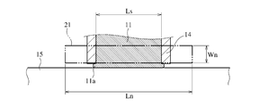
- FIG. 3 (a) is a partial sectional view showing in detail the vicinity of a molten metal nozzle in the apparatus of FIG.
- FIG. 4 is a cross-sectional view taken along line AA in FIG. It is a fragmentary sectional view which shows in detail the principal part of the further another example of the apparatus which manufactures the quenching Fe group soft magnetic alloy ribbon of this invention.
- an Fe-based soft magnetic alloy ribbon made of an Fe-based amorphous alloy or an Fe-based microcrystalline alloy having a partially crystalline phase is produced by a single roll method, it is formed between a molten metal nozzle and a cooling roll.
- the molten metal paddle oscillates.
- the vibration of the molten metal paddle is affected by the viscosity and surface tension of the molten metal paddle, the temperature distribution of the molten metal nozzle, the surface state of the cooling roll, and the like.
- there is a temperature distribution in the molten metal nozzle local deformation of the molten metal nozzle, variation in the width direction of the interval between the molten metal nozzle and the cooling roll, and the like occur.
- the molten metal paddle has a temperature distribution, oxides or the like adhere to the surface of the cooling roll contacting the molten metal paddle part having a low temperature, and the molten metal paddle vibrates.
- the vibration of the molten metal paddle increases as the width of the Fe-based soft magnetic alloy ribbon to be manufactured increases. Specifically, the vibration becomes more pronounced in an Fe-based soft magnetic alloy ribbon having a width of 20 mm or more, particularly 50 mm or more. This is considered to be because the influence of the temperature distribution of the molten metal paddle increases as the Fe-based soft magnetic alloy ribbon becomes wider.
- the irregularities of the wavy irregularities formed on the free surface of the Fe-based soft magnetic alloy ribbon increase, and as a result, the irregularities in the width direction of the individual valleys constituting the wavy irregularities also increase. Disturbances in the width direction of the valleys prevent domain wall movement and increase hysteresis loss.
- the present invention is based on the discovery that when a fine streak is formed on the surface of the cooling roll, the vibration suppression effect of the molten metal paddle is further increased by reducing the temperature distribution of the molten metal nozzle.
- FIG. 1 schematically shows the wavy irregularities 2 on the free surface of the quenched Fe-based soft magnetic alloy ribbon.
- the valley 3 constituting the wavy unevenness 2 contributes to the reduction of eddy current loss due to the subdivision of the magnetic domains, so it is desirable that the wavy unevenness 2 is formed in the entire width direction of the thin ribbon 1, If it occupies 70% or more in the width direction centering on the longitudinal center line, a sufficient effect of reducing eddy current loss can be obtained.
- the occupation ratio in the width direction of the wavy irregularities 2 is preferably 80% or more, and most preferably 100%.
- the occupancy ratio in the width direction of the wavy irregularities 2 is obtained by selecting any five regions (50 mm in the longitudinal direction) in the longitudinal direction of the ribbon 1 and averaging the occupancy rates measured in the respective regions.
- the valley 3 extending in the width direction is bent in a wave shape.
- the disturbance in the width direction of the valley 3 can be represented by the average amplitude D.
- the average amplitude D is obtained by selecting any five regions (longitudinal direction 50 mm), obtaining the average amplitude of the valley 3 in each region, and averaging it over five regions.
- the average amplitude D is measured in parallel with the longitudinal direction of the ribbon 1.
- the average amplitude D representing the widthwise disturbance of the valley 3 is 20 mm or less, in addition to the effect of reducing eddy current loss, the increase in hysteresis loss can be suppressed, so the hysteresis loss is low.
- the average amplitude D exceeds 20 mm, hysteresis loss increases. This is because the magnetic energy changes in the vicinity of the valley part 3, but if the disturbance in the width direction of the valley part 3 is large, the change in the width direction of the magnetic energy also becomes large, so that the domain wall is easily trapped at a position where the magnetic energy is low. This is probably because the movement does not occur smoothly.
- the ratio of magnetic domains having a magnetization direction that is not parallel to the longitudinal direction of the ribbon 1 increases due to the disturbance in the width direction of the trough 3, and the excitation power tends to increase.
- the average amplitude D of the valley portion 3 must be 20 mm or less.
- the average amplitude D of the valley 3 is preferably 5 mm or less, and more preferably 0.1 to 2 mm.
- the valleys 3 constituting the wavy irregularities 2 are arranged at almost regular intervals in the longitudinal direction.
- the longitudinal interval L of the valleys 3 is preferably in the range of 1 to 5 mm.
- the longitudinal interval L of the valley portion 3 is less than 1 mm, the apparent power is large, and when it exceeds 5 mm, the effect of reducing eddy current loss is reduced.
- the longitudinal interval L of the valley portions 3 is 1.5 to 3 mm.
- a peak 4 is formed in a region adjacent to the valley 3 in the longitudinal direction.
- the average height difference t between the valley 3 and the peak 4 is preferably 0.3 to 7 ⁇ m, and more preferably 1 to 4 ⁇ m.
- select any five regions (longitudinal direction 50 mm), find the average height difference between valley 3 and peak 4 in each region, and average it over 5 regions Ask.
- the thickness T of the ribbon 1 is preferably in the range of 15 to 35 ⁇ m.
- the ratio t / T between the average height difference t between the valley 3 and the peak 4 and the thickness T of the ribbon 1 is preferably in the range of 0.02 to 0.2.
- t / T is less than 0.02, the effect of reducing eddy current loss is small, and if it exceeds 0.2, not only the apparent power increases, but also the space factor of the iron core decreases.
- a more preferable range of t / T is 0.04 to 0.15.
- Fe-based amorphous alloys include Fe-B alloy, Fe-Si-B alloy, Fe-Si-BC alloy, Fe-Si-BP alloy, Fe-Si-BCP alloy, Fe-PB alloy, Fe-PC alloy, etc.
- the Fe—Si—B alloy is superior from the viewpoint of thermal stability and manufacturability.
- Fe-based amorphous soft magnetic alloy ribbon can be used as needed, Co, Ni, Mn, Cr, V, Mo, Nb, Ta, Hf, Zr, Ti, Cu, Au, Ag, Sn, Ge, Re, Ru , Zn, In, Ga, etc. may be contained.
- An example of an Fe - based amorphous alloy is Fe 100-abc M a Si b B c (atomic%) (where M is selected from Cr, Mn, Ti, V, Zr, Nb, Mo, Hf, Ta, W, and Sn) And at least one element selected from the group consisting of 0 ⁇ a ⁇ 10, 0 ⁇ b ⁇ 20, 4 ⁇ c ⁇ 20, and 10 ⁇ a + b + c ⁇ 35.
- M has an effect of promoting amorphization.
- less than 50 atomic% of Fe may be substituted with Co and / or Ni.
- Co also has an effect of improving the saturation magnetic flux density.
- At least one element selected from Zn, As, Se, Sb, In, Cd, Ag, Bi, Mg, Sc, Re, Au, a platinum group element, Y, and a rare earth element with 50% by mass or less of M It may be replaced with.
- 50 atomic% or less of the total amount of Si and B may be substituted with at least one element selected from C, Al, P, Ga and Ge.
- Fe-based microcrystalline alloys with a partially crystalline phase include Fe-Cu-Si-B alloys, Fe-Cu-Si-BC alloys, Fe-Cu-Si-BP alloys, Fe-Cu-Si-BCP alloys Fe-Cu-PB alloy, Fe-Cu-PC alloy and the like.
- Fe-based microcrystalline alloys can be selected from Co, Ni, Mn, Cr, V, Mo, Nb, Ta, Hf, Zr, Ti, Au, Ag, Sn, Ge, Re, Ru, Zn, In, Ga and the like may be contained.
- An example of an Fe - based microcrystalline alloy is Fe 100-abcd M a Si b B c Cu d (atomic%) (where M is at least selected from Ti, V, Zr, Nb, Mo, Hf, Ta, and W) 1 ⁇ elements, 0 ⁇ a ⁇ 10, 0 ⁇ b ⁇ 20, 4 ⁇ c ⁇ 20, 0.1 ⁇ d ⁇ 3, and 10 ⁇ a + b + c + d ⁇ 35).
- M has the effect of refining crystal grains during crystallization by amorphization and heat treatment.
- less than 50 atomic% of Fe may be substituted with Co and / or Ni. Co also has an effect of improving the saturation magnetic flux density.
- 50 atomic% or less of M is selected from Cr, Mn, Zn, As, Se, Sb, Sn, In, Cd, Ag, Bi, Mg, Sc, Re, Au, platinum group elements, Y and rare earth elements Further, it may be substituted with at least one element. Furthermore, in order to adjust the magnetostriction and magnetic properties of the nanocrystalline alloy, 50 atomic% or less of the total amount of Si and B may be substituted with at least one element selected from C, Al, P, Ga and Ge. .
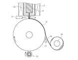
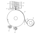
- FIG. 3 (a) shows an example of an apparatus used for manufacturing the quenched Fe-based soft magnetic alloy ribbon of the present invention.
- This apparatus includes a crucible 12 that contains an Fe-based alloy molten metal 11, a high-frequency coil 13 that is disposed on the outer periphery of the crucible 12 for heating the molten metal 11, and a crucible 12 for jetting the molten metal 11 onto a cooling roll 15.
- a melt nozzle 14 provided on the bottom surface of the steel, a peeling nozzle 17 for injecting a gas for peeling the Fe-based amorphous alloy ribbon formed by rapid cooling on the cooling roll 15, and a Fe-based amorphous alloy ribbon 16 are wound.
- the orifice of the melt nozzle 14 that ejects the melt 11 has a slit shape.
- the slit-shaped orifice opening of the heating nozzle 21 disposed in the vicinity of the molten metal paddle 11a and the molten nozzle 14 has a width Wn that sufficiently covers the molten nozzle 14. And a length Ln that sufficiently exceeds the horizontal length Ls of the slit-like orifice of the molten metal nozzle 14.
- the length Ln of the slit-like opening of the heating nozzle 21 is preferably 1.2 to 2 times Ls. It is necessary to maintain the temperature distribution in the width direction of the molten metal nozzle within ⁇ 15 ° C. so that the temperature distribution of the molten metal paddle 11a becomes as small as possible. Therefore, the temperature of the heated gas ejected from the heating nozzle 21 is preferably 800 to 1400 ° C., more preferably 1000 to 1200 ° C.
- the heating gas is preferably an inert gas such as carbon dioxide gas or argon gas.
- the wire brush roll 22 for polishing the surface of the cooling roll 15 is preferably made of a metal wire that is harder than the cooling roll 15 so as to form countless fine lines on the polishing surface of the cooling roll 15.
- a metal wire is preferably a stainless steel wire.
- the diameter of the stainless steel wire is preferably about 0.02 to 0.1 mm.
- the roughness of the fine streaks formed on the surface of the cooling roll 15 by polishing with the wire brush roll 22 is represented by the average roughness Ra and the maximum roughness Rmax.
- the average roughness Ra and the maximum roughness Rmax are not only the hardness and diameter of the metal wire, but also the pressing force of the wire brush roll 22 against the cooling roll 15, the rotation speed and rotation direction of the wire brush roll 22, and the unit area of the cooling roll 15. It depends on the number of metal wires in contact with the wire. These conditions are adjusted so that the polished surface of the cooling roll 15 has an average roughness Ra of 0.1 to 1 ⁇ m and a maximum roughness Rmax of 0.5 to 10 ⁇ m.
- the average roughness Ra is less than 0.1 ⁇ m, the vibration suppression effect of the molten metal paddle 11a cannot be sufficiently obtained, and if it exceeds 1 ⁇ m, the surface of the cooling roll 15 has too large streaks, resulting in the ultra-quenched Fe-based soft
- the magnetic properties of the magnetic alloy ribbon are reduced.
- the maximum roughness Rmax is less than 0.5 ⁇ m, the vibration suppression effect of the molten metal paddle 11a cannot be sufficiently obtained, and if it exceeds 10 ⁇ m, the streaks on the surface of the cooling roll 15 are too large, resulting in the ultra rapid cooling.
- the magnetic properties of the Fe-based soft magnetic alloy ribbon are reduced.
- a preferred average roughness Ra is 0.2 to 0.8 ⁇ m, and a preferred maximum roughness Rmax is 1 to 5 ⁇ m.
- the number of wire brush rolls 22 forming a fine stripe having the average roughness Ra and the maximum roughness Rmax is not limited to one, and two or more wire brush rolls 22 may be arranged along the rotation direction. Further, as shown in FIG. 3 (b), a deburring polishing roll 23 may be disposed on the downstream side of the wire brush roll 22 in the rotation direction.
- a buffing roll brush made of a chemical fiber in which an abrasive such as diamond abrasive grains is kneaded can be used.
- the reason why the vibration suppressing effect of the molten metal paddle 11a is greater when the polished surface of the cooling roll 15 has the finer lines than the mirror surface is not necessarily clear. Even if the surface of the cooling roll 15 is mirror-like, there is no defect such as scratches at all, and even if there is a slight defect on a part of the mirror surface, there is a great influence, and the molten metal paddle 11a is destabilized and vibrated. it is conceivable that. On the other hand, when fine streaks are formed entirely on the polished surface of the cooling roll 15, it is locally non-uniform, but on the whole, it is uniform, and some defects are present. Even if it exists, since it has an effect of mitigating the influence, it is considered that the molten metal paddle 11a is stabilized.
- the vibration suppression effect of the molten metal paddle 11a due to fine lines on the surface of the cooling roll 15 is not appropriate unless the temperature of the molten metal nozzle 14 is kept constant so that the temperature distribution of the molten metal paddle 11a becomes as small as possible. In other words, a sufficient vibration suppressing effect of the molten metal paddle 11a cannot be obtained only by forming fine stripes on the surface of the cooling roll 15 or by keeping the temperature of the molten metal nozzle 14 constant. Only when both means are used together, an appropriate vibration suppression effect of the molten metal paddle 11a can be obtained. As described above, the vibration of the molten metal paddle 11a is caused even by a slight change in conditions, and it is not easy to find a means for suppressing the vibration.
- the eddy current loss is reduced by the wavy unevenness that subdivides the magnetic domain, and the wavy unevenness We succeeded in simultaneously satisfying the difficult requirement of preventing an increase in hysteresis loss by suppressing the amplitude of the valley in the width direction.
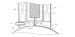
- FIG. 5 shows an example in which a hood 24 is provided to keep the temperature of the molten metal nozzle 14 constant.
- the heating nozzle 21 is fixed to the hood 24, and the slit-shaped opening is located in the hood 24. Since the heated gas ejected from the slit-shaped opening of the heating nozzle 21 flows out between the hood 24 and the cooling roll 15, the temperature distribution of the molten metal nozzle 14 can be reliably reduced.
- the obtained Fe-based soft magnetic alloy ribbon may be heat treated.
- the heat treatment is preferably performed in an inert gas such as Ar or nitrogen at a temperature of 350 to 650 ° C.
- the heat treatment time is usually 24 hours or less, preferably 5 minutes to 4 hours.
- SiO 2, MgO optionally coating such as Al 2 O 3, chemical treatment it is subjected to a treatment such as anodization good.
- the iron core of the present invention is formed by laminating or winding the quenched Fe-based soft magnetic alloy ribbon. Since both the eddy current loss and the hysteresis loss of the quenched Fe-based soft magnetic alloy ribbon of the present invention are reduced, the iron core using it has a low iron loss.
- the iron core is heat-treated in an inert gas such as nitrogen gas or Ar, in a vacuum or in the atmosphere. When a magnetic field is applied in the magnetic path direction of the iron core during the heat treatment, an iron core having a high squareness ratio and low apparent power and iron loss can be obtained. In order to obtain a high squareness ratio, a magnetic field having a strength at which the iron core is magnetically saturated is applied. The strength of the magnetic field is preferably 400 A / m or more, more preferably 800 A / m or more.
- the magnetic field to be applied is a DC magnetic field, but an AC magnetic field may be used.
- the heat treatment may be single stage or multistage.
- Example 1 In the apparatus shown in FIG. 3 (a), a ceramic melt nozzle 14 having a slit-like opening having a length of 50 mm and a width of 0.6 mm was used, and the distance between the tip of the melt nozzle 14 and the cooling roll 15 was set to 250 ⁇ m.
- the water-cooled roll 15 made of Cu—Cr—Zr alloy was rotated at a peripheral speed of 25.5 m / s. Containing 11.5 atomic% B, 9.5 atomic% Si and 0.3 atomic% C on the water-cooled roll 15 rotating from the molten metal nozzle 14 while ejecting carbon dioxide at 1250 ° C. from the heating nozzle 21, with the remainder substantially A 1300 ° C.
- molten alloy consisting of Fe and inevitable impurities was jetted out to produce a Fe-based amorphous alloy ribbon having a width of 50 mm and an average plate thickness of 24.3 ⁇ m.
- the temperature distribution in the width direction of the melt nozzle 14 was very uniform at 1200 ° C. ⁇ 10 ° C.
- a wire brush roll 11 made of stainless steel wire having a diameter of 0.06 mm was rotated in the opposite direction to the cooling roll 15 at a peripheral speed of 3 mm / s. Fine streaks having an average roughness Ra of 0.6 ⁇ m and a maximum roughness Rmax of 4.7 ⁇ m were formed on the surface of the cooling roll 15 polished by the wire brush roll 11. As a result, adhesion of oxide to the cooling roll 15 was suppressed.
- the obtained Fe-based amorphous alloy ribbon showed an amorphous halo pattern in X-ray diffraction.
- the wavy unevenness 2 formed on the free surface of the Fe-based amorphous alloy ribbon has a valley 3 continuous over a range of 80% of the width of the ribbon, the average amplitude D of the valley 3 is 8.2 mm, and the average
- the longitudinal interval L was 2.0 mm, and the average height difference t between the valley 3 and the peak 4 was 3.0 ⁇ m or less.
- Comparative Example 1 An Fe-based amorphous alloy ribbon was produced under the same conditions as in Example 1 except that heated carbon dioxide was not ejected from the heating nozzle 21.
- This Fe-based amorphous alloy ribbon showed a halo pattern in X-ray diffraction, and the wavy unevenness 2 formed on the free surface thereof had a continuous valley 3 over a range of 80% of the width of the ribbon.
- the average longitudinal distance L of the wavy unevenness 2 and the average height difference t between the valley 3 and the peak 4 were almost the same as in Example 1, but the average amplitude D of the valley 3 was remarkably large at 24.0 mm.
- Comparative Example 2 An Fe-based amorphous alloy ribbon was produced under the same conditions as in Example 1 except that the wire brush roll 11 was not used. This Fe-based amorphous alloy ribbon showed a halo pattern in X-ray diffraction, and the wavy unevenness 2 formed on the free surface thereof had a continuous valley 3 over a range of 80% of the width of the ribbon. Oxide adheres to the cooling roll 15 during long-time production, so the wavy unevenness 2 on the free surface of the Fe-based amorphous alloy ribbon is significantly disturbed, the average longitudinal interval L is 2.1 mm, and the valley 3 And the average height difference t of the peak 4 was 7.3 ⁇ m, and the average amplitude D of the valley 3 was 26.4 mm.
- Heat treatment was performed at 350 ° C. for 60 minutes while applying a magnetic field of 1500 A / m in the longitudinal direction of the Fe-based amorphous alloy ribbons of Example 1 and Comparative Examples 1 and 2.
- the direct current BH loop of the single-sheet sample of Fe-based amorphous alloy ribbon after heat treatment was measured, and the hysteresis loss Ph 1.3 / 50 at 1.3 T and 50 Hz was obtained.
- the iron loss P 1.3 / 50 and the excitation power S 1.3 / 50 at 1.3 T and 50 Hz of the single plate sample were measured by a single sheet tester (single plate magnetic property evaluation apparatus). The results are shown in Table 1.
- the hysteresis loss Ph 1.3 / 50 of the Fe-based amorphous alloy ribbon of Example 1 is 0.033 W / in which the disturbance of the wavy unevenness 2 is small (the average amplitude D of the valley 3 is as small as 8.2 mm).
- the iron loss P 1.3 / 50 was 0.053 W / kg, and the excitation power S 1.3 / 50 was 0.070 VA / kg, which was smaller than those of the Fe-based amorphous alloy ribbons of Comparative Examples 1 and 2.
- a ceramic melt nozzle 14 having a slit-like opening 30 mm long and 0.5 to 0.7 mm wide is used, and the distance between the tip of the melt nozzle 14 and the cooling roll 15 is 150 to It was set to 300 ⁇ m.
- the water-cooled roll 15 made of Cu-Be alloy was rotated at a peripheral speed of 20 to 35 m / s. While carbon dioxide at 1190 ° C was ejected from the heating nozzle 21, each molten alloy at 1250 to 1350 ° C having the composition (atomic%) shown in Table 2 was ejected onto the water-cooled roll 15 rotating from the melt nozzle 14, and the width A 30 mm Fe-based amorphous alloy ribbon was produced. During the production of the Fe-based amorphous alloy ribbon, the temperature distribution in the width direction of the melt nozzle 14 was very uniform at 1200 ° C. ⁇ 10 ° C.
- a wire brush roll 11 made of stainless steel wire having a diameter of 0.03 mm was rotated in a direction opposite to the cooling roll 15 at a peripheral speed of 4 mm / s. Fine streaks having an average roughness Ra of 0.25 ⁇ m and a maximum roughness Rmax of 2.7 ⁇ m were formed on the surface of the cooling roll 15 polished by the wire brush roll 11. As a result, adhesion of oxide to the cooling roll 15 was suppressed.
- Comparative Examples 3-6 Fe-based amorphous alloy ribbons were produced under the same conditions as in Examples 2 to 19 except that heated carbon dioxide was not ejected from the heating nozzle 21.
- the temperature distribution in the width direction of the molten metal nozzle 14 was as large as 1200 ° C. ⁇ 30 ° C.
- a wire brush roll 11 made of stainless steel wire having a diameter of 0.05 mm was rotated in a direction opposite to the cooling roll 15 at a peripheral speed of 5 mm / s. Fine streaks having an average roughness Ra of 0.4 ⁇ m and a maximum roughness Rmax of 2.3 ⁇ m were formed on the surface of the cooling roll 15 polished by the wire brush roll 11. As a result, adhesion of oxide to the cooling roll 15 was suppressed.
- the wavy unevenness 2 formed on the free surface of each Fe-based amorphous alloy ribbon has a valley 3 continuous over the range of 100% of the width of the ribbon, and the average amplitude D of the valley shown in Table 2 is 8.9 mm and average longitudinal spacing L were 2.5 mm, and an average t / T of 0.1.
- Heat treatment was performed at 350 ° C. for 60 minutes while applying a magnetic field of 1000 A / m in the longitudinal direction of the Fe-based amorphous alloy ribbons of Examples 2 to 19 and Comparative Examples 3 to 6.
- the direct current BH loop of the single-sheet sample of Fe-based amorphous alloy ribbon after heat treatment was measured, and the hysteresis loss Ph 1.3 / 50 at 1.3 T and 50 Hz was obtained.
- the iron loss P 1.3 / 50 and the excitation power S 1.3 / 50 of the single plate sample at 1.3 T and 50 Hz were measured by a single sheet tester. The results are shown in Table 3.
- the iron loss P 1.3 / 50 and the excitation power S 1.3 / 50 of the Fe-based amorphous alloy ribbons of Examples 2 to 19 are those of the Fe-based amorphous alloy ribbon of Comparative Examples 3 to 6 It was smaller. This is because the Fe-based amorphous alloy ribbons of Examples 2 to 19 have smaller hysteresis loss Ph 1.3 / 50 than the Fe-based amorphous alloy ribbons of Comparative Examples 3 to 6.
- a ceramic melt nozzle 14 having a slit-like opening 30 mm long and 0.5 to 0.7 mm wide is used, and the distance between the tip of the melt nozzle 14 and the cooling roll 15 is 150 to It was set to 300 ⁇ m.
- the water-cooled roll 15 made of Cu-Be alloy was rotated at a peripheral speed of 20 to 35 m / s. While the carbon dioxide gas at 1250 ° C was ejected from the heating nozzle 21, each molten alloy at 1250-1350 ° C having the composition (atomic%) shown in Table 4 was ejected onto the water-cooled roll 15 rotating from the melt nozzle 14, and the width A 30 mm Fe-based amorphous alloy ribbon was produced. During the production of the Fe-based amorphous alloy ribbon, the temperature distribution in the width direction of the melt nozzle 14 was very uniform at 1200 ° C. ⁇ 10 ° C.
- a wire brush roll 11 made of stainless steel wire having a diameter of 0.04 mm was rotated in a direction opposite to the cooling roll 15 at a peripheral speed of 4 mm / s. Fine streaks having an average roughness Ra of 0.5 ⁇ m and a maximum roughness Rmax of 2.5 ⁇ m were formed on the surface of the cooling roll 15 polished by the wire brush roll 11. As a result, adhesion of oxide to the cooling roll 15 was suppressed.
- Comparative Examples 7-10 Fe-based amorphous alloy ribbons were produced under the same conditions as in Examples 20 to 39 except that heated carbon dioxide was not ejected from the heating nozzle 21.
- the temperature distribution in the width direction of the melt nozzle 14 was as large as 1200 ° C. ⁇ 35 ° C.
- a wire brush roll 11 made of stainless steel wire having a diameter of 0.08 mm was rotated in the opposite direction to the cooling roll 15 at a peripheral speed of 5 mm / s. Fine streaks having an average roughness Ra of 0.7 ⁇ m and a maximum roughness Rmax of 3.9 ⁇ m were formed on the surface of the cooling roll 15 polished by the wire brush roll 11. As a result, adhesion of oxide to the cooling roll 15 was suppressed.
- the wavy unevenness 2 formed on the free surface of each Fe-based amorphous alloy ribbon has a valley 3 continuous over a range of 95% of the width of the ribbon, and the average amplitude D of the valley 3 shown in Table 4 is The average longitudinal distance L was 9.0 mm and 2.9 mm, and the average t / T was 0.1.
- the heat treatment was performed at 350 ° C. for 60 minutes while applying a magnetic field of 1000 ⁇ A / m in the longitudinal direction of each Fe-based amorphous alloy ribbon of Examples 20 to 39 and Comparative Examples 7 to 10.
- a crystal peak corresponding to the bcc-Fe phase was observed in the Fe-based amorphous alloy ribbon after the heat treatment, and it was confirmed that the amorphous phase was less than 50%.
- the average crystal grain size determined from the half width of the bcc-Fe crystal peak (Scherrer formula) was 30 nm or less.
- the direct current BH loop of the single-sheet sample of Fe-based amorphous alloy ribbon after heat treatment was measured, and the hysteresis loss Ph 1.3 / 50 at 1.3 T and 50 Hz was obtained. Furthermore, the iron loss P 1.3 / 50 and the excitation power S 1.3 / 50 of the single plate sample at 1.3 T and 50 Hz were measured by a single sheet tester. The results are shown in Table 5.
- the iron loss P 1.3 / 50 and the excitation power S 1.3 / 50 of the Fe-based amorphous alloy ribbons of Examples 20 to 39 are those of the Fe-based amorphous alloy ribbon of Comparative Examples 7 to 10. It was smaller. This is because the Fe-based amorphous alloy ribbons of Examples 20 to 39 have smaller hysteresis loss Ph 1.3 / 50 than the Fe-based amorphous alloy ribbons of Comparative Examples 7 to 10.
- Example 40 In the apparatus shown in FIG. 3 (a), a ceramic melt nozzle 14 having a slit-like opening having a length of 25 mm and a width of 0.6 mm was used, and the distance between the tip of the melt nozzle 14 and the cooling roll 15 was 240 ⁇ m.
- the water-cooled roll 15 made of Cu—Cr alloy was rotated at a peripheral speed of 25.5 m / s. Containing 15.1 atomic% B, 3.5 atomic% Si, and 0.2 atomic% C on the water-cooled roll 15 rotating from the molten metal nozzle 14 while jetting carbon dioxide at 1250 ° C from the heating nozzle 21, and the remainder substantially Then, a molten alloy of 1280 ° C.
- Fe-based amorphous alloy ribbon having a width of 25 mm and an average plate thickness of 24.7 ⁇ m.
- the temperature distribution in the width direction of the melt nozzle 14 was very uniform at 1195 ° C. ⁇ 10 ° C.
- a wire brush roll 11 made of stainless steel wire having a diameter of 0.09 mm was rotated in a direction opposite to the cooling roll 15 at a peripheral speed of 6 mm / s. Fine streaks having an average roughness Ra of 1 ⁇ m and a maximum roughness Rmax of 5 ⁇ m were formed on the surface of the cooling roll 15 polished by the wire brush roll 11. As a result, adhesion of oxide to the cooling roll 15 was suppressed.
- the obtained Fe-based amorphous alloy ribbon showed an amorphous halo pattern in X-ray diffraction.
- the wavy unevenness 2 formed on the free surface of the Fe-based amorphous alloy ribbon has a valley 3 continuous over a range of 80% of the width of the ribbon, the average amplitude D of the valley 3 is 7.4 mm, The average longitudinal distance L was 2.0 mm, and the average height difference t between the valley 3 and the peak 4 was 3.0 ⁇ m or less.
- This Fe-based amorphous alloy ribbon was wound to produce a wound core of Example 40 having an outer diameter of 75 mm and an inner diameter of 70 mm.
- Heat treatment was performed at 330 ° C. for 60 minutes while applying a magnetic field of 1000 A / m in the magnetic path direction. The heating rate and cooling rate were both 5 ° C./min.
- the DC BH loop of the heat-treated wound iron core was measured to determine the hysteresis loss Ph 1.3 / 50 at 1.3 T and 50 Hz.
- the core loss of the wound core at 1.3 T and 50 Hz was 0.055 W / kg, and the excitation power S 1.3 / 50 was 0.073 VA / kg.
- Comparative Example 11 A wound iron core was manufactured using an Fe-based amorphous alloy ribbon manufactured under the same conditions as in Example 40 except that the heated carbon dioxide gas was not ejected from the heating nozzle 21.
- the average amplitude D of the valley 3 in the wavy unevenness 2 formed on the free surface of the Fe-based amorphous alloy ribbon was 24.6 mm.
- the iron loss P 1.3 / 50 of the wound core at 1.3 T and 50 Hz was 0.103 W / kg
- the excitation power S 1.3 / 50 was 0.123 VA / kg. From this, it can be seen that if the requirements of the present invention are not satisfied, the iron loss and the excitation power increase.
Landscapes
- Engineering & Computer Science (AREA)
- Chemical & Material Sciences (AREA)
- Mechanical Engineering (AREA)
- Power Engineering (AREA)
- Materials Engineering (AREA)
- Metallurgy (AREA)
- Organic Chemistry (AREA)
- Crystallography & Structural Chemistry (AREA)
- Physics & Mathematics (AREA)
- Thermal Sciences (AREA)
- Manufacturing & Machinery (AREA)
- Inorganic Chemistry (AREA)
- Electromagnetism (AREA)
- Dispersion Chemistry (AREA)
- Soft Magnetic Materials (AREA)
- Continuous Casting (AREA)
Abstract
Priority Applications (5)
| Application Number | Priority Date | Filing Date | Title |
|---|---|---|---|
| CN201280006771.0A CN103348420B (zh) | 2011-01-28 | 2012-01-27 | 急冷Fe基软磁性合金薄带及其制造方法、以及铁心 |
| US13/981,809 US20130314198A1 (en) | 2011-01-28 | 2012-01-27 | Rapidly quenched fe-based soft-magnetic alloy ribbon and its production method and core |
| JP2012554865A JP6107140B2 (ja) | 2011-01-28 | 2012-01-27 | Fe基アモルファスの製造方法及び鉄心の製造方法 |
| DE112012000399T DE112012000399T5 (de) | 2011-01-28 | 2012-01-27 | Abgeschrecktes Band aus weichmagnetischer Legierung auf Fe-Basis und sein Herstellungsverfahren und Kern |
| US15/449,420 US10468182B2 (en) | 2011-01-28 | 2017-03-03 | Rapidly quenched Fe-based soft-magnetic alloy ribbon and its production method and core |
Applications Claiming Priority (2)
| Application Number | Priority Date | Filing Date | Title |
|---|---|---|---|
| JP2011-016017 | 2011-01-28 | ||
| JP2011016017 | 2011-01-28 |
Related Child Applications (2)
| Application Number | Title | Priority Date | Filing Date |
|---|---|---|---|
| US13/981,809 A-371-Of-International US20130314198A1 (en) | 2011-01-28 | 2012-01-27 | Rapidly quenched fe-based soft-magnetic alloy ribbon and its production method and core |
| US15/449,420 Division US10468182B2 (en) | 2011-01-28 | 2017-03-03 | Rapidly quenched Fe-based soft-magnetic alloy ribbon and its production method and core |
Publications (1)
| Publication Number | Publication Date |
|---|---|
| WO2012102379A1 true WO2012102379A1 (fr) | 2012-08-02 |
Family
ID=46580942
Family Applications (1)
| Application Number | Title | Priority Date | Filing Date |
|---|---|---|---|
| PCT/JP2012/051808 Ceased WO2012102379A1 (fr) | 2011-01-28 | 2012-01-27 | Ruban en alliage magnétique doux à base de fe traité par trempe rapide, procédé de fabrication du ruban en alliage, et noyau de fer |
Country Status (5)
| Country | Link |
|---|---|
| US (2) | US20130314198A1 (fr) |
| JP (1) | JP6107140B2 (fr) |
| CN (1) | CN103348420B (fr) |
| DE (1) | DE112012000399T5 (fr) |
| WO (1) | WO2012102379A1 (fr) |
Cited By (17)
| Publication number | Priority date | Publication date | Assignee | Title |
|---|---|---|---|---|
| WO2014142204A1 (fr) * | 2013-03-13 | 2014-09-18 | 日立金属株式会社 | Noyau magnétique enroulé et procédé pour sa fabrication |
| JP2014240516A (ja) * | 2013-06-12 | 2014-12-25 | 日立金属株式会社 | ナノ結晶軟磁性合金及びこれを用いた磁性部品 |
| WO2015046299A1 (fr) * | 2013-09-30 | 2015-04-02 | 日立金属株式会社 | Procédé de fabrication de matériau d'alliage récupéré et procédé de fabrication de ruban d'alliage amorphe récupéré |
| WO2018151172A1 (fr) | 2017-02-14 | 2018-08-23 | 日立金属株式会社 | Procédé et dispositif de fabrication de ruban d'alliage amorphe à base de fe, et corps enroulé de ruban d'alliage amorphe à base de fe |
| JPWO2017090402A1 (ja) * | 2015-11-26 | 2018-09-13 | 日立金属株式会社 | Fe基アモルファス合金リボン |
| WO2018181604A1 (fr) | 2017-03-31 | 2018-10-04 | 日立金属株式会社 | Ruban d'alliage amorphe à base de fer pour alliage nanocristallin à base de fer, et son procédé de fabrication |
| WO2019009310A1 (fr) * | 2017-07-04 | 2019-01-10 | 日立金属株式会社 | Ruban d'alliage amorphe et son procédé de fabrication |
| WO2019189813A1 (fr) | 2018-03-30 | 2019-10-03 | 日立金属株式会社 | RUBAN D'ALLIAGE AMORPHE À BASE DE Fe ET SON PROCÉDÉ DE PRODUCTION, NOYAU DE FER ET TRANSFORMATEUR |
| JPWO2019009309A1 (ja) * | 2017-07-04 | 2019-12-26 | 日立金属株式会社 | アモルファス合金リボン及びその製造方法、アモルファス合金リボン片 |
| US10519534B2 (en) | 2013-07-30 | 2019-12-31 | Jfe Steel Corporation | Iron-based amorphous alloy thin strip |
| WO2020003909A1 (fr) * | 2018-06-29 | 2020-01-02 | 株式会社村田製作所 | Bande métallique mince, son procédé de fabrication, noyau magnétique et composant de bobine |
| CN111644580A (zh) * | 2020-06-29 | 2020-09-11 | 福建省长汀金龙稀土有限公司 | 一种钕铁硼材料、其制备方法和应用 |
| US10774404B2 (en) | 2017-03-13 | 2020-09-15 | Kabushiki Kaisha Toshiba | Plurality of flaky magnetic metal particles, pressed powder material, and rotating electric machine |
| WO2020262493A1 (fr) | 2019-06-28 | 2020-12-30 | 日立金属株式会社 | Ruban d'alliage amorphe à base de fer, noyau de fer et transformateur |
| JP2021536129A (ja) * | 2018-12-17 | 2021-12-23 | チンタオ ユンルー アドバンスド マテリアルズ テクノロジー カンパニー リミテッド | 鉄基アモルファス合金ストリップ及びその製造方法 |
| WO2022196672A1 (fr) * | 2021-03-17 | 2022-09-22 | Hilltop株式会社 | Procédé de production d'une bande mince d'alliage à solidification rapide à base de fe-si-b |
| JP2023548959A (ja) * | 2020-10-27 | 2023-11-21 | エーティーアンドエム アモルファス テクノロジー カンパニー リミテッド | アモルファスナノ結晶合金薄帯及びその製造方法 |
Families Citing this family (10)
| Publication number | Priority date | Publication date | Assignee | Title |
|---|---|---|---|---|
| JP6481996B2 (ja) * | 2014-02-17 | 2019-03-13 | 日立金属株式会社 | 高周波加速空胴用磁心、及びその製造方法 |
| WO2017119787A1 (fr) * | 2016-01-06 | 2017-07-13 | 주식회사 아모그린텍 | Alliage magnétique doux à base de fer, son procédé de fabrication et pièces magnétiques utilisant l'alliage magnétique doux à base de fer |
| JP6478061B2 (ja) * | 2016-04-04 | 2019-03-06 | Jfeスチール株式会社 | 非晶質合金薄帯 |
| US11972884B2 (en) * | 2018-01-12 | 2024-04-30 | Tdk Corporation | Soft magnetic alloy and magnetic device |
| KR102619636B1 (ko) * | 2019-10-11 | 2024-01-02 | 가부시끼가이샤 도시바 | 고주파 가속 공동용 코어 및 그것을 사용한 고주파 가속 공동 |
| DE102020104311A1 (de) * | 2020-02-19 | 2021-08-19 | Vacuumschmelze Gmbh & Co. Kg | Anlage und Verfahren zum Herstellen eines Bandes mit einer Rascherstarrungstechnologie sowie metallisches Band |
| US12030115B2 (en) * | 2020-09-25 | 2024-07-09 | Metglas, Inc. | Process for in-line mechanically scribing of amorphous foil for magnetic domain alignment and core loss reduction |
| CN112695261B (zh) * | 2020-12-07 | 2022-07-15 | 青岛云路先进材料技术股份有限公司 | 铁基非晶合金带材、其制备方法与铁基非晶合金带材单辊快淬的装置 |
| JP2023031769A (ja) * | 2021-08-25 | 2023-03-09 | Tdk株式会社 | 軟磁性合金、軟磁性合金薄帯、積層体および磁性コア |
| CN116487176A (zh) * | 2023-05-09 | 2023-07-25 | 宁波中益赛威新材料有限公司 | 一种铁基纳米晶磁芯的制备方法 |
Citations (6)
| Publication number | Priority date | Publication date | Assignee | Title |
|---|---|---|---|---|
| JPH03161149A (ja) * | 1989-11-17 | 1991-07-11 | Kawasaki Steel Corp | 急冷金属薄帯の製造装置および製造方法 |
| JPH04279257A (ja) * | 1990-11-27 | 1992-10-05 | Alps Electric Co Ltd | Fe系軟磁性合金薄帯の製造方法 |
| JPH04288950A (ja) * | 1990-09-07 | 1992-10-14 | Alps Electric Co Ltd | Fe系軟磁性合金薄帯の製造装置及び製造方法 |
| JPH1064710A (ja) * | 1996-08-19 | 1998-03-06 | Sumitomo Special Metals Co Ltd | 高磁束密度を有する等方性永久磁石とその製造方法 |
| JP2001295005A (ja) * | 2000-04-14 | 2001-10-26 | Hitachi Metals Ltd | ナノ結晶軟磁性合金用Fe基アモルファス合金薄帯及び磁性部品 |
| JP2002316243A (ja) * | 2001-02-14 | 2002-10-29 | Hitachi Metals Ltd | アモルファス合金薄帯の製造方法、およびこれを用いたナノ結晶合金薄帯の製造方法 |
Family Cites Families (27)
| Publication number | Priority date | Publication date | Assignee | Title |
|---|---|---|---|---|
| JPS5518566A (en) | 1978-07-26 | 1980-02-08 | Nippon Steel Corp | Improving method for iron loss characteristic of directional electrical steel sheet |
| GB2062972B (en) * | 1979-10-19 | 1983-08-10 | Nippon Steel Corp | Iron core for electrical machinery and apparatus and well as method for producing the iron core |
| JPS5667905A (en) | 1979-11-07 | 1981-06-08 | Hitachi Metals Ltd | Improvement method of magnetic characteristic |
| US4869312A (en) * | 1983-05-02 | 1989-09-26 | Allied Corporation | Casting in an exothermic reduction atmosphere |
| DE3442009A1 (de) | 1983-11-18 | 1985-06-05 | Nippon Steel Corp., Tokio/Tokyo | Amorphes legiertes band mit grosser dicke und verfahren zu dessen herstellung |
| US4724015A (en) * | 1984-05-04 | 1988-02-09 | Nippon Steel Corporation | Method for improving the magnetic properties of Fe-based amorphous-alloy thin strip |
| JPS60233804A (ja) | 1984-05-04 | 1985-11-20 | Nippon Steel Corp | 非晶質合金薄帯の磁性改善方法 |
| JPS6124208A (ja) | 1984-07-12 | 1986-02-01 | Nippon Steel Corp | 良好な磁気特性を有する非晶質磁性材料 |
| JPH0673719B2 (ja) * | 1987-12-26 | 1994-09-21 | 新日本製鐵株式会社 | 金属薄帯の製造方法および製造用ノズル |
| CA2040741C (fr) | 1990-04-24 | 2000-02-08 | Kiyonori Suzuki | Alliage faiblement ferromagnetique, materiaux contenant cet alliage, et appareils magnetiques produits avec ces derniers |
| JP3266404B2 (ja) * | 1993-02-12 | 2002-03-18 | 川崎製鉄株式会社 | 金属薄帯の製造方法及び装置 |
| KR100309390B1 (ko) | 1993-02-12 | 2002-02-19 | 에모또 간지 | 비정질금속박대의제조방법및장치 |
| JPH06344091A (ja) * | 1993-04-12 | 1994-12-20 | Nippon Steel Corp | 異形断面薄帯の製造方法及び製造用金属ロール |
| JPH07276011A (ja) * | 1994-04-07 | 1995-10-24 | Alps Electric Co Ltd | 軟磁性合金薄帯の製造方法、製造装置、その製造方法により製造された軟磁性合金薄帯および軟磁性合金部材 |
| JPH08215799A (ja) * | 1995-02-16 | 1996-08-27 | Nippon Steel Corp | 異形断面薄帯の製造方法 |
| JPH08215800A (ja) * | 1995-02-16 | 1996-08-27 | Nippon Steel Corp | 異形断面非晶質金属薄帯 |
| JPH08215801A (ja) * | 1995-02-17 | 1996-08-27 | Nippon Steel Corp | 急冷金属薄帯およびその製造装置 |
| JP3032886B2 (ja) | 1997-03-27 | 2000-04-17 | 後藤 俊一 | 暖房空気の室内均一法 |
| JP3594123B2 (ja) | 1999-04-15 | 2004-11-24 | 日立金属株式会社 | 合金薄帯並びにそれを用いた部材、及びその製造方法 |
| EP1045402B1 (fr) | 1999-04-15 | 2011-08-31 | Hitachi Metals, Ltd. | Bande mince en alliage, magnétiquement douce, procédé de fabrication et utilisation |
| JP4529106B2 (ja) * | 2000-09-11 | 2010-08-25 | 日立金属株式会社 | アモルファス合金薄帯の製造方法 |
| US6749700B2 (en) * | 2001-02-14 | 2004-06-15 | Hitachi Metals Ltd. | Method for producing amorphous alloy ribbon, and method for producing nano-crystalline alloy ribbon with same |
| JP2005021950A (ja) * | 2003-07-03 | 2005-01-27 | Hitachi Metals Ltd | アモルファス合金薄帯の製造方法 |
| CN101961779B (zh) | 2004-06-30 | 2014-01-29 | 住友电气工业株式会社 | 镁合金材料的制造方法 |
| JP5024644B2 (ja) | 2004-07-05 | 2012-09-12 | 日立金属株式会社 | 非晶質合金薄帯 |
| TWI305548B (en) * | 2005-05-09 | 2009-01-21 | Nippon Steel Corp | Low core loss grain-oriented electrical steel sheet and method for producing the same |
| JP5445888B2 (ja) | 2005-09-16 | 2014-03-19 | 日立金属株式会社 | 軟磁性合金およびその製造方法ならびに磁性部品 |
-
2012
- 2012-01-27 WO PCT/JP2012/051808 patent/WO2012102379A1/fr not_active Ceased
- 2012-01-27 CN CN201280006771.0A patent/CN103348420B/zh active Active
- 2012-01-27 US US13/981,809 patent/US20130314198A1/en not_active Abandoned
- 2012-01-27 DE DE112012000399T patent/DE112012000399T5/de not_active Withdrawn
- 2012-01-27 JP JP2012554865A patent/JP6107140B2/ja active Active
-
2017
- 2017-03-03 US US15/449,420 patent/US10468182B2/en active Active
Patent Citations (6)
| Publication number | Priority date | Publication date | Assignee | Title |
|---|---|---|---|---|
| JPH03161149A (ja) * | 1989-11-17 | 1991-07-11 | Kawasaki Steel Corp | 急冷金属薄帯の製造装置および製造方法 |
| JPH04288950A (ja) * | 1990-09-07 | 1992-10-14 | Alps Electric Co Ltd | Fe系軟磁性合金薄帯の製造装置及び製造方法 |
| JPH04279257A (ja) * | 1990-11-27 | 1992-10-05 | Alps Electric Co Ltd | Fe系軟磁性合金薄帯の製造方法 |
| JPH1064710A (ja) * | 1996-08-19 | 1998-03-06 | Sumitomo Special Metals Co Ltd | 高磁束密度を有する等方性永久磁石とその製造方法 |
| JP2001295005A (ja) * | 2000-04-14 | 2001-10-26 | Hitachi Metals Ltd | ナノ結晶軟磁性合金用Fe基アモルファス合金薄帯及び磁性部品 |
| JP2002316243A (ja) * | 2001-02-14 | 2002-10-29 | Hitachi Metals Ltd | アモルファス合金薄帯の製造方法、およびこれを用いたナノ結晶合金薄帯の製造方法 |
Cited By (43)
| Publication number | Priority date | Publication date | Assignee | Title |
|---|---|---|---|---|
| JPWO2014142204A1 (ja) * | 2013-03-13 | 2017-02-16 | 日立金属株式会社 | 巻磁心及びその製造方法 |
| WO2014142204A1 (fr) * | 2013-03-13 | 2014-09-18 | 日立金属株式会社 | Noyau magnétique enroulé et procédé pour sa fabrication |
| KR102123138B1 (ko) * | 2013-03-13 | 2020-06-15 | 히타치 긴조쿠 가부시키가이샤 | 권자심 및 그 제조 방법 |
| CN105074841A (zh) * | 2013-03-13 | 2015-11-18 | 日立金属株式会社 | 卷绕磁芯和其制造方法 |
| KR20150131065A (ko) * | 2013-03-13 | 2015-11-24 | 히타치 긴조쿠 가부시키가이샤 | 권자심 및 그 제조 방법 |
| US9978497B2 (en) | 2013-03-13 | 2018-05-22 | Hitachi Metals, Ltd. | Wound magnetic core and method of producing the same |
| CN105074841B (zh) * | 2013-03-13 | 2017-06-16 | 日立金属株式会社 | 卷绕磁芯和其制造方法 |
| JP2014240516A (ja) * | 2013-06-12 | 2014-12-25 | 日立金属株式会社 | ナノ結晶軟磁性合金及びこれを用いた磁性部品 |
| US10519534B2 (en) | 2013-07-30 | 2019-12-31 | Jfe Steel Corporation | Iron-based amorphous alloy thin strip |
| US10407754B2 (en) | 2013-09-30 | 2019-09-10 | Hitachi Metals, Ltd. | Process for manufacturing reclaimed alloy material and process for manufacturing reclaimed amorphous alloy ribbon |
| CN105531043A (zh) * | 2013-09-30 | 2016-04-27 | 日立金属株式会社 | 再生合金材料的制造方法和再生非晶合金带的制造方法 |
| JPWO2015046299A1 (ja) * | 2013-09-30 | 2017-03-09 | 日立金属株式会社 | 再生合金材料の製造方法および再生アモルファス合金リボンの製造方法 |
| WO2015046299A1 (fr) * | 2013-09-30 | 2015-04-02 | 日立金属株式会社 | Procédé de fabrication de matériau d'alliage récupéré et procédé de fabrication de ruban d'alliage amorphe récupéré |
| JPWO2017090402A1 (ja) * | 2015-11-26 | 2018-09-13 | 日立金属株式会社 | Fe基アモルファス合金リボン |
| DE112016005437T5 (de) | 2015-11-26 | 2018-10-04 | Hitachi Metals, Ltd. | Band aus amorpher Legierung auf Fe-Basis |
| WO2018151172A1 (fr) | 2017-02-14 | 2018-08-23 | 日立金属株式会社 | Procédé et dispositif de fabrication de ruban d'alliage amorphe à base de fe, et corps enroulé de ruban d'alliage amorphe à base de fe |
| JP7070438B2 (ja) | 2017-02-14 | 2022-05-18 | 日立金属株式会社 | Fe基アモルファス合金リボンの製造方法、Fe基アモルファス合金リボンの製造装置、及びFe基アモルファス合金リボンの巻き回体 |
| JPWO2018151172A1 (ja) * | 2017-02-14 | 2019-12-12 | 日立金属株式会社 | Fe基アモルファス合金リボンの製造方法、Fe基アモルファス合金リボンの製造装置、及びFe基アモルファス合金リボンの巻き回体 |
| US10987729B2 (en) | 2017-02-14 | 2021-04-27 | Hitachi Metals, Ltd. | Fe-based amorphous alloy ribbon manufacturing method, Fe-based amorphous alloy ribbon manufacturing device, and wound body of Fe-based amorphous alloy ribbon |
| US11459645B2 (en) | 2017-03-13 | 2022-10-04 | Kabushiki Kaisha Toshiba | Plurality of flaky magnetic metal particles, pressed powder material, and rotating electric machine |
| US10774404B2 (en) | 2017-03-13 | 2020-09-15 | Kabushiki Kaisha Toshiba | Plurality of flaky magnetic metal particles, pressed powder material, and rotating electric machine |
| JPWO2018181604A1 (ja) * | 2017-03-31 | 2020-02-06 | 日立金属株式会社 | Fe基ナノ結晶合金用のFe基アモルファス合金リボン及びその製造方法 |
| WO2018181604A1 (fr) | 2017-03-31 | 2018-10-04 | 日立金属株式会社 | Ruban d'alliage amorphe à base de fer pour alliage nanocristallin à base de fer, et son procédé de fabrication |
| US11613799B2 (en) | 2017-03-31 | 2023-03-28 | Hitachi Metals, Ltd. | Fe-based amorphous alloy ribbon for Fe-based nanocrystalline alloy, and method for manufacturing the same |
| JP7111096B2 (ja) | 2017-03-31 | 2022-08-02 | 日立金属株式会社 | Fe基ナノ結晶合金用のFe基アモルファス合金リボン及びその製造方法 |
| WO2019009310A1 (fr) * | 2017-07-04 | 2019-01-10 | 日立金属株式会社 | Ruban d'alliage amorphe et son procédé de fabrication |
| JPWO2019009309A1 (ja) * | 2017-07-04 | 2019-12-26 | 日立金属株式会社 | アモルファス合金リボン及びその製造方法、アモルファス合金リボン片 |
| JPWO2019009310A1 (ja) * | 2017-07-04 | 2019-12-26 | 日立金属株式会社 | アモルファス合金リボン及びその製造方法 |
| US12002607B2 (en) | 2018-03-30 | 2024-06-04 | Proterial, Ltd. | Fe-based amorphous alloy ribbon and method for producing same, iron core, and transformer |
| WO2019189813A1 (fr) | 2018-03-30 | 2019-10-03 | 日立金属株式会社 | RUBAN D'ALLIAGE AMORPHE À BASE DE Fe ET SON PROCÉDÉ DE PRODUCTION, NOYAU DE FER ET TRANSFORMATEUR |
| JPWO2020003909A1 (ja) * | 2018-06-29 | 2021-04-22 | 株式会社村田製作所 | 金属薄帯とその製造方法、及び磁心コア、並びにコイル部品 |
| JP7040616B2 (ja) | 2018-06-29 | 2022-03-23 | 株式会社村田製作所 | 金属薄帯とその製造方法、及び磁心コア、並びにコイル部品 |
| WO2020003909A1 (fr) * | 2018-06-29 | 2020-01-02 | 株式会社村田製作所 | Bande métallique mince, son procédé de fabrication, noyau magnétique et composant de bobine |
| US12084735B2 (en) | 2018-06-29 | 2024-09-10 | Murata Manufacturing Co., Ltd. | Metal strip and manufacturing method therefor, magnetic core, and coil component |
| JP2021536129A (ja) * | 2018-12-17 | 2021-12-23 | チンタオ ユンルー アドバンスド マテリアルズ テクノロジー カンパニー リミテッド | 鉄基アモルファス合金ストリップ及びその製造方法 |
| JP7463348B2 (ja) | 2018-12-17 | 2024-04-08 | チンタオ ユンルー アドバンスド マテリアルズ テクノロジー カンパニー リミテッド | 鉄基アモルファス合金ストリップ及びその製造方法 |
| WO2020262494A1 (fr) | 2019-06-28 | 2020-12-30 | 日立金属株式会社 | Ruban d'alliage amorphe à base de fe et son procédé de production, noyau de fer et transformateur |
| WO2020262493A1 (fr) | 2019-06-28 | 2020-12-30 | 日立金属株式会社 | Ruban d'alliage amorphe à base de fer, noyau de fer et transformateur |
| EP4258302A2 (fr) | 2019-06-28 | 2023-10-11 | Proterial, Ltd. | Ruban d'alliage amorphe à base de fe, noyau de fer et transformateur |
| CN111644580A (zh) * | 2020-06-29 | 2020-09-11 | 福建省长汀金龙稀土有限公司 | 一种钕铁硼材料、其制备方法和应用 |
| JP2023548959A (ja) * | 2020-10-27 | 2023-11-21 | エーティーアンドエム アモルファス テクノロジー カンパニー リミテッド | アモルファスナノ結晶合金薄帯及びその製造方法 |
| WO2022196672A1 (fr) * | 2021-03-17 | 2022-09-22 | Hilltop株式会社 | Procédé de production d'une bande mince d'alliage à solidification rapide à base de fe-si-b |
| JPWO2022196672A1 (fr) * | 2021-03-17 | 2022-09-22 |
Also Published As
| Publication number | Publication date |
|---|---|
| US20130314198A1 (en) | 2013-11-28 |
| US20170178805A1 (en) | 2017-06-22 |
| JPWO2012102379A1 (ja) | 2014-07-03 |
| DE112012000399T5 (de) | 2013-10-10 |
| CN103348420A (zh) | 2013-10-09 |
| CN103348420B (zh) | 2016-06-15 |
| US10468182B2 (en) | 2019-11-05 |
| JP6107140B2 (ja) | 2017-04-05 |
Similar Documents
| Publication | Publication Date | Title |
|---|---|---|
| JP6107140B2 (ja) | Fe基アモルファスの製造方法及び鉄心の製造方法 | |
| JP5656114B2 (ja) | 超急冷Fe基軟磁性合金薄帯および磁心 | |
| JP5720674B2 (ja) | 初期超微結晶合金、ナノ結晶軟磁性合金及びその製造方法、並びにナノ結晶軟磁性合金からなる磁性部品 | |
| JP4402960B2 (ja) | 軟磁気特性に優れたFe基非晶質合金薄帯、それを用いて製造した鉄心およびそれらに用いる急冷凝固薄帯製造用母合金 | |
| JP5327074B2 (ja) | 軟磁性合金薄帯及びその製造方法、並びに軟磁性合金薄帯を有する磁性部品 | |
| JP6131856B2 (ja) | 初期超微結晶合金薄帯 | |
| US6749700B2 (en) | Method for producing amorphous alloy ribbon, and method for producing nano-crystalline alloy ribbon with same | |
| JP6237630B2 (ja) | 超微結晶合金薄帯、微結晶軟磁性合金薄帯及びこれを用いた磁性部品 | |
| JP6080094B2 (ja) | 巻磁心およびこれを用いた磁性部品 | |
| JP6003899B2 (ja) | Fe基初期超微結晶合金薄帯及び磁性部品 | |
| JP2008231533A (ja) | 軟磁性薄帯、磁心、磁性部品、および軟磁性薄帯の製造方法 | |
| CN104010748A (zh) | 超微晶合金薄带的制造方法 | |
| CN112442642B (zh) | 金属带、制备非晶金属带的方法和纳米晶金属带制备方法 | |
| JP7111096B2 (ja) | Fe基ナノ結晶合金用のFe基アモルファス合金リボン及びその製造方法 | |
| JP2002316243A (ja) | アモルファス合金薄帯の製造方法、およびこれを用いたナノ結晶合金薄帯の製造方法 | |
| JP4257629B2 (ja) | ナノ結晶軟磁性合金用Fe基アモルファス合金薄帯及び磁性部品 | |
| JP2000328206A (ja) | 軟磁性合金薄帯ならびにそれを用いた磁心、装置およびその製造方法 | |
| JP5645108B2 (ja) | 非晶質合金薄帯および非晶質合金薄帯を有する磁性部品 | |
| JP4437563B2 (ja) | 表面性状に優れた磁性合金ならびにそれを用いた磁心 | |
| CN117561132A (zh) | Fe-Si-B类厚板急冷凝固合金薄带的制造方法 | |
| JP2001300697A (ja) | ナノ結晶材用アモルファスリボンの製造方法及びこれを用いたナノ結晶軟磁性材料の製造方法 | |
| JPH04288950A (ja) | Fe系軟磁性合金薄帯の製造装置及び製造方法 | |
| JPH04288952A (ja) | Fe系軟磁性合金薄帯の製造方法 |
Legal Events
| Date | Code | Title | Description |
|---|---|---|---|
| 121 | Ep: the epo has been informed by wipo that ep was designated in this application |
Ref document number: 12738931 Country of ref document: EP Kind code of ref document: A1 |
|
| ENP | Entry into the national phase |
Ref document number: 2012554865 Country of ref document: JP Kind code of ref document: A |
|
| WWE | Wipo information: entry into national phase |
Ref document number: 13981809 Country of ref document: US |
|
| WWE | Wipo information: entry into national phase |
Ref document number: 112012000399 Country of ref document: DE Ref document number: 1120120003993 Country of ref document: DE |
|
| 122 | Ep: pct application non-entry in european phase |
Ref document number: 12738931 Country of ref document: EP Kind code of ref document: A1 |