WO2012102400A1 - Dent de stator, stator, induit tournant et procédé de commande de l'induit tournant - Google Patents
Dent de stator, stator, induit tournant et procédé de commande de l'induit tournant Download PDFInfo
- Publication number
- WO2012102400A1 WO2012102400A1 PCT/JP2012/051895 JP2012051895W WO2012102400A1 WO 2012102400 A1 WO2012102400 A1 WO 2012102400A1 JP 2012051895 W JP2012051895 W JP 2012051895W WO 2012102400 A1 WO2012102400 A1 WO 2012102400A1
- Authority
- WO
- WIPO (PCT)
- Prior art keywords
- switch
- winding
- stator
- windings
- stator teeth
- Prior art date
- Legal status (The legal status is an assumption and is not a legal conclusion. Google has not performed a legal analysis and makes no representation as to the accuracy of the status listed.)
- Ceased
Links
Images











Classifications
-
- H—ELECTRICITY
- H02—GENERATION; CONVERSION OR DISTRIBUTION OF ELECTRIC POWER
- H02K—DYNAMO-ELECTRIC MACHINES
- H02K3/00—Details of windings
- H02K3/04—Windings characterised by the conductor shape, form or construction, e.g. with bar conductors
- H02K3/28—Layout of windings or of connections between windings
-
- H—ELECTRICITY
- H02—GENERATION; CONVERSION OR DISTRIBUTION OF ELECTRIC POWER
- H02K—DYNAMO-ELECTRIC MACHINES
- H02K1/00—Details of the magnetic circuit
- H02K1/06—Details of the magnetic circuit characterised by the shape, form or construction
- H02K1/12—Stationary parts of the magnetic circuit
- H02K1/14—Stator cores with salient poles
-
- H—ELECTRICITY
- H02—GENERATION; CONVERSION OR DISTRIBUTION OF ELECTRIC POWER
- H02K—DYNAMO-ELECTRIC MACHINES
- H02K21/00—Synchronous motors having permanent magnets; Synchronous generators having permanent magnets
- H02K21/12—Synchronous motors having permanent magnets; Synchronous generators having permanent magnets with stationary armatures and rotating magnets
- H02K21/14—Synchronous motors having permanent magnets; Synchronous generators having permanent magnets with stationary armatures and rotating magnets with magnets rotating within the armatures
- H02K21/16—Synchronous motors having permanent magnets; Synchronous generators having permanent magnets with stationary armatures and rotating magnets with magnets rotating within the armatures having annular armature cores with salient poles
-
- H—ELECTRICITY
- H02—GENERATION; CONVERSION OR DISTRIBUTION OF ELECTRIC POWER
- H02K—DYNAMO-ELECTRIC MACHINES
- H02K3/00—Details of windings
- H02K3/04—Windings characterised by the conductor shape, form or construction, e.g. with bar conductors
- H02K3/18—Windings for salient poles
- H02K3/20—Windings for salient poles for auxiliary purposes, e.g. damping or commutating
-
- H—ELECTRICITY
- H02—GENERATION; CONVERSION OR DISTRIBUTION OF ELECTRIC POWER
- H02P—CONTROL OR REGULATION OF ELECTRIC MOTORS, ELECTRIC GENERATORS OR DYNAMO-ELECTRIC CONVERTERS; CONTROLLING TRANSFORMERS, REACTORS OR CHOKE COILS
- H02P25/00—Arrangements or methods for the control of AC motors characterised by the kind of AC motor or by structural details
- H02P25/16—Arrangements or methods for the control of AC motors characterised by the kind of AC motor or by structural details characterised by the circuit arrangement or by the kind of wiring
- H02P25/18—Arrangements or methods for the control of AC motors characterised by the kind of AC motor or by structural details characterised by the circuit arrangement or by the kind of wiring with arrangements for switching the windings, e.g. with mechanical switches or relays
-
- H—ELECTRICITY
- H02—GENERATION; CONVERSION OR DISTRIBUTION OF ELECTRIC POWER
- H02P—CONTROL OR REGULATION OF ELECTRIC MOTORS, ELECTRIC GENERATORS OR DYNAMO-ELECTRIC CONVERTERS; CONTROLLING TRANSFORMERS, REACTORS OR CHOKE COILS
- H02P27/00—Arrangements or methods for the control of AC motors characterised by the kind of supply voltage
- H02P27/04—Arrangements or methods for the control of AC motors characterised by the kind of supply voltage using variable-frequency supply voltage, e.g. inverter or converter supply voltage
- H02P27/16—Arrangements or methods for the control of AC motors characterised by the kind of supply voltage using variable-frequency supply voltage, e.g. inverter or converter supply voltage using AC to AC converters without intermediate conversion to DC
Definitions
- the present invention relates to a stator tooth, a stator, a rotating electrical machine including the stator, and a method for controlling the rotating electrical machine.
- Permanent magnet synchronous motor uses a permanent magnet for the rotor, so it is a motor with higher output and higher efficiency than induction machines and other motors.
- a punched silicon steel plate is laminated and used for the stator, and a coil is wound around the silicon steel plate.
- an induced voltage is generated in the coil.
- a voltage higher than the induced voltage is applied from the inverter connected to the coil, and a current synchronized with the rotation is applied to the coil.
- the rotor generates torque by flowing the current.
- control called field weakening control is control in which a magnetic flux that is opposed to a magnetic flux generated by a magnet is generated from a coil so that the magnetic flux of the magnet does not interlink with the coil.
- the field weakening control since the magnetic flux of the magnet appears to be weakened, the induction machine voltage is lowered and the rotation speed is increased.
- variable field structure two types of magnets with different force (coercive force) to hold the magnetic flux of the magnet are arranged on the rotor, and the magnetic flux direction of the magnet with weak coercive force is maintained by an external current.
- the structure is opposite to that of a strong magnet.
- Patent Document 1 and Patent Document 2 the coil wound around the stator is divided into two, and when the rotational speed is slow, the two are connected in series, and when the rotational speed is fast, the two coils are divided. By using only half, the magnetic flux linked to the coil can be reduced to half.
- Patent Document 3 the coil wound around the stator is separated into two, and when the rotation speed is high and the torque is low, the windings are connected in parallel, and when the rotation speed is low and the torque is high.
- a technique for reducing the magnetic flux linked to the coil in half by connecting the windings in series is disclosed.
- Patent Document 4 a magnet disposed on a rotor is made rotatable so that when the rotational speed is slow, the magnet is disposed in a direction facing the coil. When the rotational speed is fast, the magnet is oriented parallel to the coil.
- a technique for arranging magnets is disclosed. Since the magnet arranged in the direction parallel to the coil has a small area when viewed from the coil, the magnetic flux linked to the coil can be reduced.
- variable field structure in order to maintain the polarity of the magnet having a weak coercive force, it is necessary to energize a continuous current, and there is a problem that efficiency is lowered. Further, a space for arranging a magnet having a weak coercive force is required on the rotor, and there is a problem that the output is lowered as compared with a motor having a magnet having a strong coercive force. Furthermore, in order to reverse the polarity of the magnet having a weak coercive force, it is necessary to flow a large current instantaneously, resulting in a problem that the inverter capacity becomes large and the dielectric strength of the coil needs to be increased.
- Patent Literature 1 when only half of the coil is used, the current cannot be increased. Therefore, the torque is higher than when two coils are connected and used. There is a problem of halving.
- the present invention has been made in view of the above-described circumstances.
- a single motor can exhibit a plurality of driving characteristics without increasing the size of the apparatus, and the output range can be expanded.
- the problem is to plan.
- a stator tooth according to the present invention is a stator tooth attached to a stator yoke, and includes at least two windings wound around the stator tooth and the two windings. An end of one of the windings and at least one switch connected to the end of the other winding, wherein the switch is another winding wound around another stator tooth. It is also possible to connect to the end of the line (first mode).
- the stator according to the present invention is a stator including a stator yoke and a stator tooth that is formed integrally with the stator yoke or attached to the stator yoke, and is wound around the stator tooth. At least two windings, At least one switch connected to an end of one of the two windings and an end of the other set of windings, the switch surrounding the other stator teeth It is connectable also to the edge part of the other winding wound by (2nd aspect).
- the rotating electrical machine is a stator tooth formed integrally with a rotor having a permanent magnet and a stator yoke, or attached to the stator yoke, and at least with respect to one pole pair of the permanent magnet
- a rotor having a permanent magnet and a stator tooth formed integrally with the stator yoke or attached to the stator yoke, wherein one pole of the permanent magnet is provided.
- At least three or more stator teeth provided for the pair, at least two windings wound around each of the stator teeth, and an end of one of the two windings
- at least one switch provided on each of the stator teeth, and the switch is connected to the other end of the other stator teeth.
- a method for controlling a rotating electrical machine connected to an end of a winding wherein the rotational speed required for the rotating electrical machine is lower than a predetermined reference speed
- the switch is switched so that the end of one of the two windings is connected to the end of the other winding, and the rotational speed required for the rotating electrical machine is a predetermined reference If higher than the speed, the switch is connected to the end of one of the two windings and the end of the other winding wound around the other stator teeth.
- the winding of the winding wound around the stator teeth by switching the switch.
- the connection state can be freely changed between concentrated winding and distributed winding according to the rotation speed, so multiple drive characteristics can be achieved with one motor and the output range can be expanded without increasing the size of the device. be able to.
- the connection between windings to which a positive voltage is to be applied in each phase is intermittently switched at a predetermined ratio
- the connection between windings to which a negative voltage is to be applied is
- the connection between windings to which a positive voltage is to be applied is always connected.
- the voltage applied to the winding may be changed from a DC voltage to an AC voltage (sixth aspect).
- control method of the sixth aspect it is not necessary to connect an inverter to the outside, and the system can be reduced in size.
- the winding connection state in each phase is the concentrated winding state in which the end of one of the two windings and the end of the other winding are connected Or two states in a distributed winding state in which an end of one of the two windings and an end of another winding wound around the other stator teeth are connected
- the switch may be switched so as to switch in time finely according to the voltage target value, and the induced voltage may be a sine wave (seventh aspect).
- torque ripple can be reduced and reduction of iron loss can be achieved.
- the switch is a control method for a rotating electrical machine connected to an end of another winding wound around another stator tooth, the switch being When switching so that the end of one of the two windings and the end of the other winding wound around the other stator teeth are connected, each stator tooth
- the switches may be switched so as to be connected to different windings at the same time, and the switches may be switched so that the number of windings included in each phase is equal (eighth mode).
- the imbalance between the phases can be eliminated.
- the switch includes a switch for connecting or disconnecting the windings wound at least three in series and one winding wound around one stator tooth.
- a switch that connects or disconnects the wire and one winding wound around another stator tooth, and is connected to a current supply end among the windings wound around each stator tooth The winding at the end opposite to the winding of the part is connected to the winding at the end opposite to the winding at the end connected to the current supply end in the pair of stator teeth.
- a switch for connecting or disconnecting the end winding connected to the current supply end of each stator tooth and the end winding connected to the current supply end of the paired stator teeth.
- a rotor having a permanent magnet and a stator tooth formed integrally with the stator yoke or attached to the stator yoke, At least six or more stator teeth provided for one pole pair of magnets, at least three windings wound around each of the stator teeth, and at least three windings wound
- a first switch that connects or disconnects the first switch, one winding wound around one stator tooth, and one winding wound around another stator tooth. Of the windings wound around each stator tooth, on the opposite side of the winding at the end connected to the current supply end.
- the winding of the part is connected to the winding of the end opposite to the winding of the end connected to the current supply end of the pair of stator teeth, and is connected to the current supply end of each stator tooth.
- a three-phase alternating current to a rotating electrical machine having a third switch for connecting or disconnecting a winding at one end and a winding at an end connected to a current supply end in a pair of stator teeth.
- the first switch is turned on at least three windings.
- the first switch When the first connection mode that is switched so as to be connected in series and the rotational speed required for the rotating electrical machine is higher than a predetermined reference speed, the first switch is disconnected and the second switch is Stators Switching between the first connection mode and the second connection mode is performed by switching the alternating current of any phase.
- the third switch When it is detected that the value has become zero, the third switch is connected to the winding of the end connected to the current supply end of the stator tooth to which the alternating current of the phase is supplied, and the pair of stator teeth. The windings of the stator teeth to which the alternating current of the phase is supplied by the first switch, respectively.
- One winding wound around the stator teeth of the phase by the second switch when it is detected that the alternating current value of any one of the phases becomes zero next Are connected to one winding wound around other stator teeth. Further, with respect to a plurality of other stator teeth, one winding wound around each stator tooth and other stator teeth are connected to the other stator teeth. One winding wound is connected, and the stator is paired with the winding at the end connected to the current supply end of the stator teeth to which the alternating current of the phase is supplied by the third switch. Switching between the second connection mode and the first connection mode is performed by disconnecting the winding at the end connected to the current supply end in the teeth, and the alternating current value of any phase is zero. When it is detected that the winding has been achieved, the windings are connected and disconnected by a procedure reverse to the above procedure (tenth aspect).
- a rotor having a permanent magnet and a stator tooth formed integrally with the stator yoke or attached to the stator yoke, At least six or more stator teeth provided for one pole pair of magnets, at least three windings wound around each of the stator teeth, and at least three windings wound A first switch that connects or disconnects the first switch, one winding wound around one stator tooth, and one winding wound around another stator tooth. Of the windings wound around each stator tooth, on the opposite side of the winding at the end connected to the current supply end.
- the winding of the part is connected to the winding of the end opposite to the winding of the end connected to the current supply end of the pair of stator teeth, and is connected to the current supply end of each stator tooth.
- a three-phase alternating current to a rotating electrical machine having a third switch for connecting or disconnecting a winding at one end and a winding at an end connected to a current supply end in a pair of stator teeth.
- a second connection mode that switches so as to connect other stator teeth, and switching from the first connection mode to the second connection mode is performed by alternating current of any phase.
- the third switch is connected to the winding of the end connected to the current supply end of the stator tooth to which the alternating current of the phase is supplied, and the pair of stator teeth. The windings of the stator teeth to which the alternating current of the phase is supplied by the first switch, respectively.
- the winding of each phase is changed from the concentrated winding to the common winding at the timing when the current of each phase becomes zero.
- a current that is three times the current flows in the common winding during the period from the period when the current of each phase becomes zero to the period when the current becomes zero.
- a current that is the same as that before the connection of the common winding flows, so that no torque ripple is generated.
- switching from 2 series to distributed winding does not cause a voltage spike at the time of switching, and the winding can be switched without loss.
- the first connection aspect and the second connection aspect are finely divided in time according to a voltage target value.
- the switch is switched so as to switch, and the induced voltage is changed to a sine wave (a twelfth aspect).
- the first connection mode and the second connection mode are switched at the timing when the current of each phase becomes 0, torque ripple is not generated. Further, no voltage spike is generated at the time of switching, and the winding can be switched without loss.
- the switch in the stator teeth of the first aspect, is a bidirectional switch in which the source terminals of the MOSFETs or the drain terminals are connected to each other (the thirteenth aspect). ).
- the switch in the stator of the second aspect, is a bidirectional switch in which source terminals or drain terminals of MOSFETs are connected to each other (fourteenth aspect). .
- the switch is a bidirectional switch in which source terminals of MOSFETs or drain terminals are connected to each other.
- the switch in the method for controlling a rotating electric machine according to the fourth aspect, the sixth aspect, or the seventh aspect, is a bidirectional device in which MOSFET source terminals or drain terminals are connected to each other. It is a switch (16th aspect).
- stator teeth of the thirteenth aspect, the stator of the fourteenth aspect, the rotating electric machine of the fifteenth aspect, and the control method of the rotating electric machine of the sixteenth aspect of the present invention since the bidirectional switch is used, the connection between the windings to be disconnected Can be reliably separated.
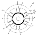
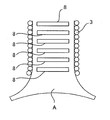
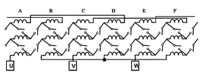
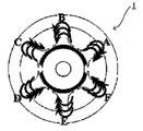
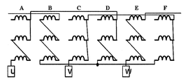
- FIG. 3 is a diagram showing a configuration of stator teeth A of the permanent magnet synchronous motor 1. It is a figure which shows the connection state of each group of coils of stator teeth A to F and a switch. It is a figure which shows the connection state of the coil and switch when each coil of stator teeth A to F is concentrated winding. It is a figure explaining each coil of stator teeth A to F being concentrated winding. It is a figure which shows the connection state of the coil and switch when each coil of the stator teeth A to F is distributed winding. It is a figure explaining each coil of stator teeth A to F being distributed winding.
- FIG. 2 is a block diagram illustrating a configuration of a control device for the permanent magnet synchronous motor 1.
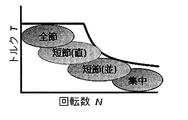
- FIG. It is a figure which shows the characteristic at the time of making each coil of stator teeth A-F into concentrated winding. It is a figure which shows the characteristic at the time of making each coil of stator teeth A-F into distributed winding. It is a figure which shows the change of the induced voltage at the time of switching a coil from concentrated winding to distributed winding during rotation of the permanent magnet synchronous motor 1.
- FIG. It is a connection diagram at the time of concentrated winding parallel connection which concerns on 2nd Embodiment of this invention. It is a figure for demonstrating the three-phase inverter for motor drive in 3rd Embodiment of this invention.
- FIG. 1 It is a figure which shows the drive example of an inverter. It is a block diagram which shows the structure of the control apparatus of the motor 1 which concerns on 3rd Embodiment of this invention. It is a figure which shows the connection state of the coil and switch which concern on 3rd Embodiment of this invention. It is a figure which shows the connection state of the coil and switch which concern on 4th Embodiment of this invention. It is a figure which shows switching of the coil connection state according to the drive range which concerns on 5th Embodiment of this invention. It is a figure which shows the connection state of the coil and switch which concern on 6th Embodiment of this invention.
- FIG. 1 is a diagram showing a configuration of a permanent magnet synchronous motor having two poles (one pole pair) and six slots (number of stator teeth: 6) according to the first embodiment of the present invention.
- a permanent magnet synchronous motor 1 is formed of a stator yoke 2 formed of a silicon steel plate and the like, and also formed of a silicon steel plate or the like, and can be fixed to the stator yoke 2 integrally or to the stator yoke 2.
- the stator 4 is composed of six stator teeth A, B, C, D, E, and F. Inside the six stator teeth A to F, a rotor 7 having N pole 5 and S pole 6 permanent magnets on the outer peripheral portion is rotatably provided.
- FIG. 2 is a diagram showing a configuration of one stator tooth A. As shown in FIG. As shown in FIG. 2, a single stator tooth A is wound with a predetermined number of coils 3, and each coil 3 is connected via a switch 8.
- the switch 8 may be a semiconductor switching element such as a power transistor or a solid state relay. A switch other than the semiconductor switching element may be used. Further, in the example of FIG. 2, the switch 8 is provided on the stator teeth, but the present invention is not limited to this example, and the switch 8 may be provided outside the motor 1.
- FIG. 3 is a diagram showing a connection state between each coil 3 of each stator tooth A to F and the switch 8 in the present embodiment.
- two switches are connected to the end of the first coil (the uppermost part in FIG. 3) of each stator tooth. Also, two switches are connected to the end of the second coil (second from the top in FIG. 3). That is, a total of four switches are connected to one stator tooth coil. In FIG. 2, four switches 8 are shown corresponding to this connection state.
- the mounting position of the switch 8 is not limited to the position shown in FIG.
- the switch 8 between the first coil 3 and the second coil 3 of each stator tooth A to F is turned on, and the second coil 3 of each stator tooth A to F
- the switch 8 between the third coil 3 is turned on.
- the other switches 8 are turned off.
- the coil 3 is wound in a concentrated manner.
- the switch 8 between the second coil 3 of each stator tooth A to F and the first coil 3 of the status tooth adjacent counterclockwise is turned on, and each stator tooth is turned on.
- the switch 8 between the third coil 3 of A to F and the second coil 3 of the status tooth adjacent counterclockwise is turned on.
- the other switches 8 are turned off.
- the coil 3 is in a state of being wound with distributed winding (full-pitch winding).
- the motor 1 of this embodiment can control the connection state of the coils 3 of the stator teeth A to F by switching the switch 8 on and off.
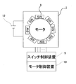
- the connection state of the coil 3 is controlled by a control device as shown in FIG.
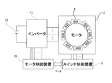
- a switch control device 9 is connected to each switch 8, and a motor control device 10 is connected to the switch control device 9.
- the motor control device 10 outputs data corresponding to the on / off pattern of each switch 8 to the switch control device 9, and the switch control device 9 switches on / off of each switch 8 based on the data. .
- an inverter 11 is connected to the motor control device 10, and the output of the inverter 11 is connected to the input ends of the coils 3 of the stator teeth A to F.
- the inverter 11 of the present embodiment is a three-phase output inverter using six switching elements.
- the inverter 11 performs PWM switching based on a control signal from the motor control device 10, converts a direct current supplied from the battery 12 into a three-phase alternating current, and supplies it to the coil 3. As a result, the rotation speed of the motor 1 and the output torque are adjusted.
- the inverter 11 since the three-phase motor 1 is used, the inverter 11 also has a three-phase output, but the present invention is not limited to this example. When a motor having three or more phases is used, an appropriate inverter may be used.
- the winding is in a distributed winding state.
- the stator teeth A, the stator teeth B, and the coils 3 of the stator teeth C are connected in series one by one. And the sum of the magnetic fluxes of stator teeth B and stator teeth C.
- FIG. 10 is a graph showing a state in which the induced voltage decreases when the coil connection state is switched from concentrated winding to distributed winding during rotation.
- the characteristics shown in FIG. 9 are obtained by switching the coil winding state between the concentrated winding state shown in FIG. 4 and the distributed winding state shown in FIG.
- Both characteristics shown in FIG. 10 can be used. That is, although it is a single motor, it has a plurality of drive characteristics and can improve the output range. Further, in an operation region that can be covered by both, it is possible to improve efficiency by selecting an efficient driving method.
- a predetermined reference value is set for the rotational speed or torque according to the characteristics of the motor, etc.
- the coil winding state is set to the concentrated winding state and the distributed winding with the reference value as a threshold value. It is sufficient to switch to the state.
- a switch may be provided at both ends of each set, or one switch is provided at the one end of the first and second coils, and the other end of the second coil and the end of the third coil.
- One switch may be provided in the unit. That is, it is only necessary to realize switching of the coil connection state as described above, and the number of switches and the mounting position are not limited.
- FIG. 12 is a connection diagram at the time of concentrated winding parallel connection according to the second embodiment of the present invention. As an example, connection of only the U phase is shown. In this example, switches 8 are provided at both ends of the three coils 3 in each of the stator teeth A to F, and all the ends of the three coils 3 are connected. As a result, the coil 3 is in a concentrated winding state in parallel connection.
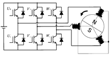
- FIG. 13 shows a configuration of a three-phase inverter for driving a motor
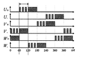
- FIG. 14 shows a 120-degree energization switching pattern as a simple driving example of this inverter.
- the third embodiment of the present invention is an embodiment that realizes the function of this inverter by turning on / off the switch 8 without providing an inverter outside the motor 1.
- the U-phase formed by the third coil 3 of the stator teeth A, the second coil 3 of the stator teeth B, and the first coil 3 of the stator teeth C Connect one end of the to the positive terminal. Further, the one end of the first coil 3 of the stator teeth C is connected to the neutral point. Further, one end of the V phase formed by the third coil 3 of the stator teeth E, the second coil 3 of the stator teeth F, and the first coil 3 of the stator teeth A is connected to the negative terminal.
- the switch 8 that connects the third coil 3 of the stator tooth A and the second coil 3 of the stator tooth B, and the second coil 3 of the stator tooth B and the first coil 3 of the stator tooth C.
- PWM switching is performed by repeatedly turning on / off the switch 8 connecting the two at a certain ratio.
- the current is U + from the DC power supply positive terminal, the third coil 3 of the stator tooth A, and the second coil of the stator tooth B. 3, the first coil 3 of the stator teeth C, the neutral point, the first coil 3 of the stator teeth A, the second coil 3 of the stator teeth F, the third coil 3 of the stator teeth E, V ⁇ , minus It will flow in the order of the terminals.
- the inverter function can be realized by setting the predetermined switch 8 to the PWM switching and ON state in a predetermined section without providing an inverter outside the motor 1. . Therefore, the system can be downsized.
- FIG. 17 shows a fourth embodiment of the present invention in which the coils 3 are in different connection states for each phase.
- the third coil 3 of the stator tooth C and the third coil of the stator tooth F among the six coils in the V phase are connected by a connection method as shown in FIG.
- the magnetic flux is linked only to two coils of the coil 3.
- the magnetic flux is linked to the four coils of the third and third coils 3 of the stator teeth A and the second and third coils 3 of the stator teeth D.
- magnetic fluxes are linked to six coils including all the coils 3 of the stator teeth E and all the coils 3 of the stator teeth B.
- the induced voltage can be changed to a sine wave by finely switching the connection method of the coil according to requirements.
- the edge connected to the edge part of the 1st coil of another adjacent stator teeth among the edge parts of the 2nd coil of each stator teeth may be changed, or the switch may be added so that the portion is connected to the corresponding end of the first coil of the same stator teeth.
- the end portion connected to the end portion of the second coil of the other adjacent stator teeth is the second coil of the same stator teeth. What is necessary is just to change the connection state of a switch or to add a switch so that it may be connected to the corresponding edge part.
- FIG. 18 shows a configuration example of the fifth embodiment of the present invention in which the coil connection state is switched according to the drive range.
- all-node winding (distributed winding) is performed in the low-speed and high-torque region, concentrated winding is performed in the high-speed and low-torque region, and the series and parallel windings are switched between them.
- the switching method is not limited to the example of FIG. 17 and can be appropriately selected depending on each motor configuration.
- FIG. 19 and 20 show the connection configuration of the coil according to the sixth embodiment of the present invention.
- the coils as shown in FIG. 20 are connected, as shown in FIG. 21, the coil 3 wound on the rotor side of the stator teeth is more affected by the leakage magnetic flux than the coil 3 wound on the stator yoke side. Will become bigger. As a result, an imbalance between phases occurs.
- the coils when connecting to coils of adjacent stator teeth, the coils are connected to different coils so that the number of coils in each set included in each phase is equal. .
- coils between adjacent stator teeth are different, and the number of first coils, second coils, and third coils in each phase is two.
- the unbalance between the phases can be eliminated.
- the coil may be wound around the stator teeth in the stator in which the stator yoke and the stator teeth are integrated, or after the coils are wound around the stator teeth, the stator teeth are coupled to the stator yoke.
- the present invention is provided as a stator tooth having the above-described switch around which a coil is wound as described above, as a stator including such a stator tooth, and further including such a stator. Each can be realized as a motor.
- a switch for switching a connection state between adjacent coils wound around one stator tooth, or a switch for switching a connection state between coils wound around each adjacent stator tooth is formed by a MOSFET. This is an example of a configured bi-directional switch.
- the coil 3a and the coil 3b shown in FIG. 22 are two adjacent coils wound around one stator tooth, or a coil wound around one stator tooth and a stator tooth winding adjacent to the stator tooth.
- the coil is shown.
- One end of the bidirectional switch 8 ' is connected to one end of the coil 3a, and the other end of the bidirectional switch 8' is connected to one end of the coil 3b.
- FIG. 23 is a diagram showing the configuration of the bidirectional switch 8 ′.
- the bidirectional switch 8 ′ of this embodiment includes an N-type MOSFET 20 and another N-type MOSFET 21.
- the source terminal S of the N-type MOSFET 20 and the source terminal S of the N-type MOSFET 21 are connected to each other.
- the drain terminal D of the N-type MOSFET 20 is connected to one end of the coil 3a, and the drain terminal D of the N-type MOSFET 21 is connected to one end of the coil 3b.
- a parasitic diode 20a is formed in the N-type MOSFET 20, and a parasitic diode 21a is formed in the N-type MOSFET 21.
- FIG. 24 is a diagram showing a control circuit for the bidirectional switches 8 ′ and 8 ′′.
- the MOSFET 20 and the gate terminal of the MOSFET 21 of the bidirectional switch 8 ′ are switch-controlled through a gate resistor Rg. It is connected to the device 9.
- the source terminals of the MOSFET 20 and the MOSFET 21 are grounded via the current cutoff resistor Rb.
- the gate terminals of the MOSFET 20 ′ and the MOSFET 21 ′ of the bidirectional switch 8 ′′ are the gate resistance Rg. It is connected to the switch control device 9 via
- the source terminals of the MOSFET 20 'and the MOSFET 21' are grounded via the current cutoff resistor Rb.
- switch control device 9 is not shown in FIG. 24, the switch control device 9 is connected to the motor control device 10 as shown in FIG. 8 or FIG. 15, and based on the control data output from the motor control device 10.
- the MOSFET is switched on / off.
- the switch control device 9 applies a high level voltage to the gate terminals of the MOSFET 20 and the MOSFET 21, and applies a low level voltage to the gate terminals of the MOSFET 20 'and the MOSFET 21'.
- the MOSFET 20 and the MOSFET 21 are turned on, and the MOSFET 20 'and the MOSFET 21' are turned off.
- the current is input to the source terminal of the MOSFET 21 and flows to the coil 3b via the parasitic diode 21a of the MOSFET 21.
- the current is input to the source terminal of the MOSFET 20 and flows to the coil 3a via the parasitic diode 20a of the MOSFET 20.
- the switch between the coils is composed of a single MOSFET without using a bidirectional switch, either of the two coils is turned off by a parasitic diode formed on the MOSFET, even though the MOSFET is off. Current may flow in the direction.
- the bidirectional switch is used as the switch between the coils, the connection and disconnection of the coil can be reliably controlled.
- the gate resistance Rg is a resistance for adjusting the on / off switching speed of the MOSFET 20 'and the MOSFET 21', and the resistance value is set according to the characteristics of the MOSFET to be used. Specifically, it is about several ohms.
- the current cutoff resistor Rb causes the current from the bidirectional switch in the on state to flow to the bidirectional switch in the off state through the ground line, and further to the coil connected to the bidirectional switch in the off state. It is provided to prevent this.
- the current interruption resistance Rb is used for such a purpose, a resistance of several M ⁇ is used.
- a silicon (Si) -based one may be used, but if a silicon carbide (SiC) -based or gallium nitride (GaN) -based one is used, the resistance decreases and a larger current flows. it can.
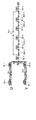
- SiC silicon carbide
- GaN gallium nitride
- bidirectional switch of the present embodiment can be applied to the switches of any of the embodiments described above.
- the present embodiment has described an example using an N-type MOSFET, a P-type MOSFET may be used.
- the motor of the present invention is driven from concentrated winding driving to distributed winding driving without generating a period in which no current flows in any coil of the stator teeth in a period other than the period in which the current of each phase becomes zero. It is related with the method of switching to.
- FIG. 26 is a circuit diagram of the motor of this embodiment. As shown in FIG. 26, the stator teeth A and the stator teeth D through which a U-phase current flows are respectively provided with coils 3A-1, 3A-2, 3A-3, and coils 3D-1, 3D-2, 3D. Three coils of -3 are wound.
- connection and disconnection of the coil 3A-1 and the coil 3A-2 are performed by the switch 8A-1, and connection and disconnection of the coil 3A-2 and the coil 3A-3 are performed by the switch 8A-2. Similarly, connection and disconnection of 3D-1 and coil 3D-2 are performed by switch 8D-1, and connection and disconnection of coil 3D-2 and coil 3D-3 are performed by switch 8D-2.
- stator teeth C and stator teeth F there are three coils 3C-1, 3C-2, 3C-3 and 3F-1, 3F-2, 3F-3 for stator teeth C and stator teeth F through which a V-phase current flows, respectively.
- Each coil is wound.
- connection and disconnection of the coil 3C-1 and the coil 3C-2 are performed by the switch 8C-1. Connection and disconnection of the coil 3C-2 and the coil 3C-3 are performed by the switch 8C-2. Similarly, connection and disconnection of 3F-1 and coil 3F-2 are performed by switch 8F-1, and connection and disconnection of coil 3F-2 and coil 3F-3 are performed by switch 8F-2.
- connection and disconnection of the coil 3E-1 and the coil 3E-2 are performed by a switch 8E-1. Connection and disconnection of the coil 3E-2 and the coil 3E-3 are performed by a switch 8E-2. Similarly, connection and disconnection of 3B-1 and coil 3B-2 are performed by switch 8B-1, and connection and disconnection of coil 3B-2 and coil 3B-3 are performed by switch 8B-2.
- connection and disconnection of the coils of the stator teeth A and the coils of the stator teeth B are performed by the switches 8AB-1 and 8AB-2.
- Connection and disconnection of the coils of the stator teeth B and the coils of the stator teeth C are performed by the switches 8BC-1 and 8BC-2.
- Connection and disconnection of the coils of the stator teeth C and the coils of the stator teeth D are performed by the switches 8CD-1 and 8CD-2.
- Connection and disconnection of the coils of the stator teeth D and the coils of the stator teeth E are performed by the switch 8DE-1 and the switch 8DE-2.
- connection and disconnection of the coils of the stator teeth E and the coils of the stator teeth F are performed by the switches 8EF-1 and 8EF-2.
- connection and disconnection of the coil of the stator teeth F and the coil of the stator teeth G are similarly performed by two switches.
- switches Sc1, Sc2, and Sc3 are provided between common windings that are commonly used for concentrated winding and distributed winding, and the common windings are connected and disconnected.
- the switch Sc1 is used to connect and disconnect the switch 3A-1 and the switch 3D-1, which are common windings. Further, connection and disconnection of the common winding switches 3B-1 and 3E-1 are performed by the switch Sc2. The switch Sc3 connects and disconnects the common winding switches 3C-1 and 3F-1.
- the concentrated winding state in which the coils of the respective stator teeth are connected in series is the state before switching in the present embodiment, and the current flows as indicated by the hatched arrows.
- FIG. 26 shows an example of current flowing in the U phase.
- the common windings 3A-1 and 3D-1 are connected by turning on the switch Sc1. By connecting the common winding in this way, in the period in which a negative current flows after the period III shown in FIG. 25, a current three times that before the period III flows in the common winding.
- the U-phase current becomes a zero current period in the period VI of the switching period. Therefore, in this period, the switches 8AB-1, 8BC-1, 8EF-1, and 8DE-1 are turned on in order to connect the coils of the stator teeth A, B, C, F, E, and D.
- the state where the coils of each stator tooth are connected in this way is a distributed winding state, and a current flows as shown by an arrow indicated by a dot in FIG.
- the common winding since the common winding is connected before the switching, the common winding is three times as long as the common winding in the period from the period when the current of each phase becomes 0 to the period when it becomes 0 next. A current flows, and as a total current of each phase, a current that is the same as that before the connection of the common winding flows, so that no trill ripple is generated.
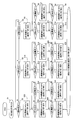
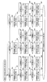
- FIG. 27 to 33 the connection states of the windings in FIGS. 27 to 33 and the flowcharts in FIGS. 34 and 35.
- step S1 when a switching command is input (step S1), whether the U-phase current is 0 (step S2), whether the V-phase current is 0 (step S3), or whether the W-phase current is 0. Is determined (step S4).
- step S4 when the W-phase current becomes 0 (step S4: YES) as in the timing t0 shown in FIG. 25, the switch 8B-1 and the switch 8B-2, and the switch 8E-2 and the switch 8E-1 is turned off and switch Sc2 is turned on, so that the W-phase winding is switched from concentrated winding drive to two series of common winding coils 3B-1 and 3E-1 (step S5).
- connection state of the windings of each phase is as shown in FIG. 28, and current flows as shown by arrows in FIG.
- step S10 it is determined whether the U-phase current is 0 (step S10) or the V-phase current is 0 (step S6).
- step S6 YES
- the switch 8C-1 and the switch 8C-2, and the switch 8F-2 and the switch The 8F-1 is turned off and the switch Sc3 is turned on, so that the V-phase winding is switched from the concentrated winding driving to the two series of the coil 3C-1 and the coil 3F-1 of the common winding (step) S7).
- connection state of the windings of each phase is as shown in FIG. 29, and current flows as shown by arrows in FIG.
- step S8 it is determined whether or not the U-phase current is 0 (step S8). For example, when the U-phase current becomes 0 (step S8: YES) as in the timing t2 shown in FIG.
- the switch 8A-1 and the switch 8A-2, and the switch 8D-2 and the switch 8D-1 are turned off and the switch Sc1 is turned on, so that the U-phase winding is shared from the concentrated winding drive.
- the winding coil 3A-1 and coil 3D-1 are switched to two series (step S9).
- step S5 After the W-phase winding is switched from concentrated winding drive to two series of common windings (step S5), when the U-phase current becomes 0 (step S10: YES), the switch 8A-1 And the switch 8A-2 and the switch 8D-2 and the switch 8D-1 are turned off and the switch Sc1 is turned on so that the U-phase winding is changed from the concentrated winding drive to the common coil 3A. -1 and coil 3D-1 are switched to two series (step S11).
- step S12 it is determined whether or not the V-phase current is 0 (step S12). If the V-phase current becomes 0 (step S12: YES), the switch 8C-1 and the switch 8C-2, and The switch 8F-2 and the switch 8F-1 are turned off and the switch Sc3 is turned on so that the V-phase winding is connected to the common winding coils 3C-1 and 3F-1 from the concentrated winding drive. Two are switched in series (step S13).
- Step S1 After inputting the switching command (step S1), for example, when the V-phase current becomes 0 at the timing t1 shown in FIG. 25 (step S3: YES), the switches 8C-1 and 8C-2, Further, the switch 8F-2 and the switch 8F-1 are turned off, and the switch Sc3 is turned on, so that the V-phase winding is changed from the concentrated winding drive to the common winding coils 3C-1 and 3F- 1 is switched to 2 in series (step S14).
- step S15 it is determined whether the U-phase current is 0 (step S15) or the W-phase current is 0 (step 19), and the U-phase current becomes 0 at the timing t2 shown in FIG. If this occurs (step S15: YES), the switch 8A-1 and the switch 8A-2, and the switch 8D-2 and the switch 8D-1 are turned off and the switch Sc1 is turned on so that the U-phase The winding is switched from concentrated winding driving to two series of common winding coils 3A-1 and 3D-1 (step S16).
- step S17 it is determined whether or not the W-phase current has become 0 (step S17). If the W-phase current has become 0 (step S17: YES), the switches 8B-1 and 8B-2, and The switch 8E-2 and the switch 8E-1 are turned off and the switch Sc2 is turned on, so that the W-phase winding is switched from the concentrated winding drive to the common winding coils 3B-1 and 3E-1. Are switched in series (step S18).
- Step S14 After the V-phase winding is switched from concentrated winding drive to two series of common windings (step S14), when the W-phase current becomes 0 (step S19: YES), the switch 8B-1 And switch 8B-2, and switch 8E-2 and switch 8E-1 are turned off, and switch Sc2 is turned on to change the W-phase winding from concentrated winding drive to common winding coil 3B. -1 and the coil 3E-1 are switched to two series (step S20).
- step S21 it is determined whether or not the U-phase current has become 0 (step S21). If the U-phase current has become 0 (step S21: YES), the switches 8A-1 and 8A-2, and The switch 8D-2 and the switch 8D-1 are turned off and the switch Sc1 is turned on so that the U-phase winding is switched from the concentrated winding drive to the common winding coils 3A-1 and 3D-1. Are switched in series (step S22).
- Step S1 After inputting the switching command (step S1), for example, when the U-phase current becomes 0 at the timing t2 shown in FIG. 25 (step S2: YES), the switch 8A-1 and the switch 8A-2, Further, the switch 8D-2 and the switch 8D-1 are turned off, and the switch Sc1 is turned on, so that the U-phase winding is switched from the concentrated winding drive to the common winding coils 3A-1 and 3D- 1 is switched to 2 in series (step S23).
- step S26 it is determined whether or not the V-phase current is 0 (step S26). If the V-phase current becomes 0 (step S26: YES), the switch 8C-1, the switch 8C-2, and the switch The 8F-2 and the switch 8F-1 are turned off and the switch Sc3 is turned on, so that the V-phase winding is switched from the concentrated winding drive to the common winding coils 3C-1 and 3F-1. Switching to serial (step S27).
- Step S23 After the U-phase winding is switched from the concentrated winding drive to the two-series drive of the common winding (step S23), when the V-phase current becomes 0 (step S28: YES), the switch 8C-1 And the switch 8C-2 and the switch 8F-2 and the switch 8F-1 are turned off and the switch Sc3 is turned on so that the V-phase winding is changed from the concentrated winding drive to the common coil 3C. -1 and coil 3F-1 are switched in series (step S29).
- step S30 it is determined whether or not the W-phase current is 0 (step S30). If the W-phase current becomes 0 (step S30: YES), the switch 8B-1, the switch 8B-2, and the switch 8E-2 and switch 8E-1 are turned off, and switch Sc2 is turned on, so that the W-phase winding is switched from the concentrated winding drive to the common winding coils 3B-1 and 3E-1. Switching to serial (step S31).
- Step S40 After switching all three phase windings to two series of common windings as in any of the examples described above, whether the U-phase current is 0 (step S40) or the V-phase current is 0. Whether or not the W-phase current is 0 (step S42).
- step S42 If it is determined that the W-phase current has become 0 as shown at timing t3 shown in FIG. 25 (step S42: YES), the switch Sc2 is turned off, and the common winding coil 3B-1 and coil 3E-1 2 Disconnect the series. Then, the switch 8BC-1 and the switch 8CD-2, and the switch 8FA-2 (not shown in FIG. 25) and 8EF-1 are turned on to drive the W phase in distributed winding (step S43).
- connection state of the windings of each phase in this state is as shown in FIG. 31, and the current flows as shown by arrows in FIG.
- Step S48 it is determined whether the U-phase current is 0 (step S48) or the V-phase current is 0 (step S44), and the V-phase current is 0 as shown at timing t4 shown in FIG. (Step S44: YES), the switch Sc3 is turned off to disconnect the two series of the common winding coils 3C-1 and 3F-1. Then, the switch 8CD-1 and the switch 8DE-2 and the switches 8AB-2 and 8FA-1 (not shown in FIG. 25) are turned on to drive the V phase in distributed winding (step S45).
- connection state of the windings of each phase in this state is as shown in FIG. 32, and the current flows as shown by arrows in FIG.
- step S46 it is determined whether or not the U-phase current is 0 (step S46).
- step S46: YES the switch Sc1 is used. Is turned off, and the two series of the coil 3A-1 and the coil 3D-1 of the common winding are disconnected. Then, the switches 8AB-1 and 8BC-2, and the switches 8EF-2 and 8DE-1 are turned on to drive the U phase in distributed winding (step S47).
- the winding of each phase is switched from concentrated winding to two series of common windings.
- the current of the common winding will flow three times as much as before, and the total current of each phase is the connection of the common winding. Since the same current flows as before, torque ripple is not generated.
- Step S43 After the W-phase winding is switched from two series to distributed winding drive (step S43), when the U-phase current becomes 0 (step S48: YES), the switch Sc1 is turned off and the common winding is turned on. The two series of wire coil 3A-1 and coil 3D-1 are disconnected. Then, the switches 8AB-1 and 8BC-2 and the switches 8EF-2 and 8DE-1 are turned on to drive the U phase in distributed winding (step S49).
- step S50 it is determined whether or not the V-phase current has become 0 (step S50). If the V-phase current has become 0 (step S50: YES), the switch Sc3 is turned off and the common winding is turned on. The two series of the coil 3C-1 and the coil 3F-1 are disconnected. Then, the switches 8CD-1 and 8DE-2 and the switches 8AB-2 and 8FA-1 (not shown in FIG. 25) are turned on to drive the V phase in distributed winding (step S51).
- Step S41: YES current of the V phase becomes 0
- step S41: YES current of the V phase becomes 0
- step S42: YES current of the V phase becomes 0
- step S52 the switch 8CD-1 and the switch 8DE-2 and the switches 8AB-2 and 8FA-1 (not shown in FIG. 25) are turned on to drive the V phase in distributed winding (step S52).
- step S53 it is determined whether the U-phase current is 0 (step S53) or the W-phase current is 0 (step S57), and the U-phase current is set to 0 as shown at timing t5 shown in FIG. If this happens (step S53: YES), the switch Sc1 is turned off to disconnect the two series of the common winding coils 3A-1 and 3D-1. Then, the switches 8AB-1 and 8BC-2, and the switches 8EF-2 and 8DE-1 are turned on to drive the U phase in distributed winding (step S54).
- step S55 it is determined whether or not the W-phase current is 0 (step S55). If the W-phase current becomes 0 (step S55: YES), the switch Sc2 is turned off and the common winding coil is turned on. Disconnect the 2 series of 3B-1 and coil 3E-1. Then, the switch 8BC-1 and the switch 8CD-2, and the switch 8FA-2 (not shown in FIG. 25) and 8EF-1 are turned on to drive the W phase in distributed winding (step S56).
- step S59 it is determined whether or not the U-phase current is 0 (step S59). If the U-phase current becomes 0 (step S59: YES), the switch Sc1 is turned off to The two series of the coil 3A-1 and the coil 3D-1 are disconnected. Then, the switches 8AB-1 and 8BC-2, and the switches 8EF-2 and 8DE-1 are turned on to drive the U phase in distributed winding (step S60).
- Step S40 YES
- the switch Sc1 is turned off.
- the two series of the common winding coils 3A-1 and 3D-1 are disconnected.
- the switches 8AB-1 and 8BC-2, and the switches 8EF-2 and 8DE-1 are turned on to drive the U phase in distributed winding (step S61).
- step S66 it is determined whether the V-phase current is 0 (step S66) or the W-phase current is 0 (step S62). If the W-phase current becomes 0 (step S62: YES), the switch Sc2 is turned off, and the two series of the coil 3B-1 and the coil 3E-1 of the common winding are disconnected. Then, the switch 8BC-1 and the switch 8CD-2, and the switch 8FA-2 (not shown in FIG. 25) and 8EF-1 are turned on to drive the W phase in distributed winding (step S63).
- step S64 it is determined whether or not the V-phase current has become 0 (step S64). If the V-phase current has become 0 (step S64: YES), the switch Sc3 is turned off and the common winding is turned on. The two series of the coil 3C-1 and the coil 3F-1 are disconnected. Then, the switch 8CD-1 and the switch 8DE-2 and the switches 8AB-2 and 8FA-1 (not shown in FIG. 25) are turned on to drive the V phase in distributed winding (step S65).
- step S68 it is determined whether or not the W-phase current is 0 (step S68). If the W-phase current becomes 0 (step S68: YES), the switch Sc2 is turned off and the common winding coil is turned on. Disconnect the 2 series of 3B-1 and coil 3E-1. Then, the switch 8BC-1 and the switch 8CD-2, and the switch 8FA-2 (not shown in FIG. 25) and 8EF-1 are turned on to drive the W phase in distributed winding (step S69).
- the winding of each phase is switched from concentrated winding to two series of common windings.
- the current of the common winding will flow three times as much as before, and the total current of each phase is the connection of the common winding. Since the same current flows as before, torque ripple is not generated.
- this embodiment demonstrated the example which switches the winding of each phase from concentrated winding drive to distributed winding drive at the time of 120 degree energization drive, it is applied also to the case of energization drive of an angle other than at the time of 120 degree energization drive. Is possible.
- a bidirectional switch as described in the seventh embodiment may be used.
- connection state of the winding wound around the stator teeth between concentrated winding and distributed winding according to the rotational speed By freely changing the connection state of the winding wound around the stator teeth between concentrated winding and distributed winding according to the rotational speed, multiple drive characteristics can be achieved with one motor without increasing the size of the device. It can be applied to the purpose of expanding the output range.
- SYMBOLS 1 Motor (rotary electric machine), 2 ... Stator yoke, 3, 3a, 3b ... Coil (winding), 3A-1, 3A-2, 3A-3, 3B-1, 3B-2, 3B-3, 3C -1, 3C-2, 3C-3, 3D-1, 3D-2, 3D-3, 3E-1, 3E-2, 3E-3, 3F-1, 3F-2, 3F-3,. 4) Stator, 5, 6 ... Permanent magnet, 7 ... Rotor, 8 ...
- Switch 8A-1, 8A-2, 8B-1, 8B-2, 8C-1, 8C-2, 8D-1, 8D-2, 8E-1, 8E-2, 8F-1, 8F-2, 8AB-1, 8AB-2, 8BC-1, 8BC-2, 8CD-1, 8CD-2, 8DE-1, 8DE- 2, 8EF-1, 8EF-2, 8FA-1, 8FA-2 ... switch, 8 ', 8 "... bidirectional switch, 9 ... switch control device, 10 ... mode Controller, 20, 20 ', 21, 21' ... MOSFET, 20a, 21a ... parasitic diode, A to F ... stator teeth, Rb ... current interruption resistance, Rg ... gate resistance.
Landscapes
- Engineering & Computer Science (AREA)
- Power Engineering (AREA)
- Control Of Ac Motors In General (AREA)
- Windings For Motors And Generators (AREA)
- Iron Core Of Rotating Electric Machines (AREA)
- Permanent Magnet Type Synchronous Machine (AREA)
Abstract
Priority Applications (5)
| Application Number | Priority Date | Filing Date | Title |
|---|---|---|---|
| EP12739300.7A EP2670028B1 (fr) | 2011-01-27 | 2012-01-27 | Dent de stator, stator, machine électrique tournante et procédé de commande de la machine électrique tournante |
| US13/982,407 US9287745B2 (en) | 2011-01-27 | 2012-01-27 | Stator teeth, stator, rotating electric machine, and method for controlling rotating electric machine |
| CN201280006749.6A CN103339835B (zh) | 2011-01-27 | 2012-01-27 | 定子齿、定子、旋转电机、及旋转电机的控制方法 |
| KR1020137019712A KR101504856B1 (ko) | 2011-01-27 | 2012-01-27 | 고정자 티스, 고정자, 회전 전기자, 및 회전 전기자의 제어 방법 |
| JP2012554875A JP5725572B2 (ja) | 2011-01-27 | 2012-01-27 | ステータティース、ステータ、回転電機、および、回転電機の制御方法 |
Applications Claiming Priority (2)
| Application Number | Priority Date | Filing Date | Title |
|---|---|---|---|
| JP2011015774 | 2011-01-27 | ||
| JP2011-015774 | 2011-01-27 |
Publications (1)
| Publication Number | Publication Date |
|---|---|
| WO2012102400A1 true WO2012102400A1 (fr) | 2012-08-02 |
Family
ID=46580963
Family Applications (1)
| Application Number | Title | Priority Date | Filing Date |
|---|---|---|---|
| PCT/JP2012/051895 Ceased WO2012102400A1 (fr) | 2011-01-27 | 2012-01-27 | Dent de stator, stator, induit tournant et procédé de commande de l'induit tournant |
Country Status (6)
| Country | Link |
|---|---|
| US (1) | US9287745B2 (fr) |
| EP (1) | EP2670028B1 (fr) |
| JP (1) | JP5725572B2 (fr) |
| KR (1) | KR101504856B1 (fr) |
| CN (1) | CN103339835B (fr) |
| WO (1) | WO2012102400A1 (fr) |
Cited By (6)
| Publication number | Priority date | Publication date | Assignee | Title |
|---|---|---|---|---|
| CN103151855A (zh) * | 2013-03-26 | 2013-06-12 | 胡风华 | 一种多枚体电机 |
| JP2015142391A (ja) * | 2014-01-27 | 2015-08-03 | 三菱電機株式会社 | 回転電機 |
| JP2016063571A (ja) * | 2014-09-16 | 2016-04-25 | スズキ株式会社 | 回転電機 |
| JP2019080449A (ja) * | 2017-10-26 | 2019-05-23 | 三菱電機株式会社 | 駆動システム |
| JP2022536225A (ja) * | 2018-11-19 | 2022-08-15 | スマート イー, エルエルシー | 無潤滑遠心圧縮機 |
| JP2023091581A (ja) * | 2021-12-20 | 2023-06-30 | コアレスモータ株式会社 | 回転電気機械及び電動車 |
Families Citing this family (28)
| Publication number | Priority date | Publication date | Assignee | Title |
|---|---|---|---|---|
| US9729016B1 (en) | 2012-03-20 | 2017-08-08 | Linear Labs, Inc. | Multi-tunnel electric motor/generator |
| US10284029B2 (en) | 2012-03-20 | 2019-05-07 | Linear Labs, LLC | Brushed electric motor/generator |
| US10263480B2 (en) * | 2012-03-20 | 2019-04-16 | Linear Labs, LLC | Brushless electric motor/generator |
| EP2828962B1 (fr) | 2012-03-20 | 2021-05-12 | Linear Labs, Inc. | Moteur électrique/générateur cc amélioré ayant des densités de flux à aimant permanent supérieures |
| FR3016755B1 (fr) * | 2014-01-17 | 2017-11-24 | Save Ingenierie | Procede de gestion d'une machine electromagnetique permettant la modification de la topologie d'un circuit d'induits de ladite machine |
| CN104158364A (zh) * | 2014-09-11 | 2014-11-19 | 吕三元 | 一种超高效三相异步电动机 |
| US9641112B2 (en) * | 2014-12-10 | 2017-05-02 | Clark Equipment Company | Protection method for a generator |
| US10447103B2 (en) | 2015-06-28 | 2019-10-15 | Linear Labs, LLC | Multi-tunnel electric motor/generator |
| CA3004702A1 (fr) | 2015-10-20 | 2017-04-27 | Linear Labs, LLC | Machine electrique a flux circonferentiel a mecanismes d'affaiblissement de champ et son procede d'utilisation |
| KR101642234B1 (ko) * | 2015-11-04 | 2016-07-22 | 한양대학교 산학협력단 | 전기모터 |
| US9621099B1 (en) * | 2016-04-22 | 2017-04-11 | GM Global Technology Operations LLC | Method for switching between a full winding mode and a half winding mode in a three-phase machine |
| US10486537B2 (en) * | 2016-08-29 | 2019-11-26 | Hamilton Sundstrand Corporation | Power generating systems having synchronous generator multiplex windings and multilevel inverters |
| CN106253532A (zh) * | 2016-08-31 | 2016-12-21 | 江门市蓬江区硕泰电器有限公司 | 一种双线绕组线圈及电机 |
| CA3034629A1 (fr) | 2016-09-05 | 2018-03-08 | Linear Labs, LLC | Moteur/generateur electrique multi-tunnel ameliore |
| DE102016218664A1 (de) | 2016-09-28 | 2018-03-29 | Robert Bosch Gmbh | Elektromotor mit einer Mehrzahl von ringförmig angeordneten Statorspulen |
| CN110168866A (zh) * | 2016-11-09 | 2019-08-23 | Tvs电机股份有限公司 | 具有多区段绕组线圈和开关组合的定子的电机 |
| US10498274B2 (en) | 2016-11-10 | 2019-12-03 | Hamilton Sundstrand Corporation | High voltage direct current system for a vehicle |
| US11043880B2 (en) | 2016-11-10 | 2021-06-22 | Hamilton Sunstrand Corporation | Electric power generating system with a synchronous generator |
| CA3042300A1 (fr) * | 2017-03-21 | 2018-09-27 | Tti (Macao Commercial Offshore) Limited | Moteur sans balais |
| GB2563624B (en) * | 2017-06-20 | 2020-04-08 | Dyson Technology Ltd | A compressor |
| US11139722B2 (en) | 2018-03-02 | 2021-10-05 | Black & Decker Inc. | Motor having an external heat sink for a power tool |
| JP7202798B2 (ja) * | 2018-07-11 | 2023-01-12 | 株式会社ミツバ | 三相回転電機の駆動装置及び三相回転電機ユニット |
| EP3618268B1 (fr) * | 2018-08-29 | 2024-07-24 | ABB Schweiz AG | Commande d'une machine électrique |
| US11277062B2 (en) | 2019-08-19 | 2022-03-15 | Linear Labs, Inc. | System and method for an electric motor/generator with a multi-layer stator/rotor assembly |
| US20220200401A1 (en) | 2020-12-23 | 2022-06-23 | Black & Decker Inc. | Brushless dc motor with circuit board for winding interconnections |
| KR102555421B1 (ko) * | 2021-01-04 | 2023-07-12 | 한양대학교 에리카산학협력단 | 동기전동기 |
| CN115664296A (zh) * | 2022-11-11 | 2023-01-31 | 哈尔滨理工大学 | 一种定子绕组重构切换拓扑以及电机系统 |
| CN116743030B (zh) * | 2023-06-28 | 2024-08-30 | 浙江海川电气科技有限公司 | 一种永磁无刷变档电机 |
Citations (7)
| Publication number | Priority date | Publication date | Assignee | Title |
|---|---|---|---|---|
| JPH06205573A (ja) * | 1992-12-28 | 1994-07-22 | Honda Motor Co Ltd | 巻線切替型回転電機 |
| JP3596711B2 (ja) | 1996-10-21 | 2004-12-02 | 株式会社安川電機 | 工作機用モータの巻線切替装置 |
| JP2005006400A (ja) * | 2003-06-11 | 2005-01-06 | Sumitomo Electric Ind Ltd | モータ駆動機構 |
| JP3695344B2 (ja) | 2001-04-16 | 2005-09-14 | 日産自動車株式会社 | 回転電機 |
| JP2005354807A (ja) | 2004-06-10 | 2005-12-22 | Yaskawa Electric Corp | 永久磁石同期電動機 |
| JP3968673B2 (ja) | 1997-11-25 | 2007-08-29 | 株式会社安川電機 | 永久磁石同期電動機の巻線切り替え方法 |
| JP2009278841A (ja) * | 2008-05-19 | 2009-11-26 | Toyota Industries Corp | 可動電機 |
Family Cites Families (49)
| Publication number | Priority date | Publication date | Assignee | Title |
|---|---|---|---|---|
| DE2235086C3 (de) * | 1972-07-18 | 1979-01-18 | Gerhard Berger Gmbh & Co Fabrik Elektrischer Messgeraete, 7630 Lahr | Schrittmotor mit fünf Statorwicklungen |
| US4035701A (en) * | 1975-03-27 | 1977-07-12 | Grundfor A/S | Method of stepwise speed control and three-phase squirrel-cage motor |
| DE2629642C3 (de) * | 1976-07-01 | 1979-08-30 | Siemens Ag, 1000 Berlin Und 8000 Muenchen | Polumschaltbare Dreiphasenwicklung |
| US4477760A (en) * | 1983-03-24 | 1984-10-16 | Westinghouse Electric Corp. | Continuous pole amplitude modulated electric machines |
| US4675591A (en) * | 1985-04-19 | 1987-06-23 | A. O. Smith Corporation | Induction motor winding |
| EP0210047A3 (fr) * | 1985-07-16 | 1987-09-30 | Maghemite Inc. | Contrôle de moteur et son fonctionnement |
| US4772842A (en) * | 1986-03-25 | 1988-09-20 | Siemens Aktiengesellschaft | Drive arrangement with a three-phase motor |
| MY106025A (en) * | 1989-09-27 | 1995-02-28 | Satake Eng Co Ltd | Y-delta conversion switches on dual stator induction motor |
| JPH0815377B2 (ja) * | 1989-10-05 | 1996-02-14 | 株式会社佐竹製作所 | 二固定子三相かご形誘導電動機 |
| FI912532A7 (fi) * | 1990-05-26 | 1991-11-27 | Satake Eng Co Ltd | Synkronmotor med dubbelstator. |
| ES2084186T3 (es) * | 1990-10-09 | 1996-05-01 | Stridsberg Licensing Ab | Un tren de potencia electrico para vehiculos. |
| JP3037471B2 (ja) * | 1991-07-05 | 2000-04-24 | ファナック株式会社 | 誘導電動機の巻線切換駆動方式 |
| US5483111A (en) * | 1994-03-23 | 1996-01-09 | Power Superconductor Applications Corp. | Method and apparatus for elimination of the exit-edge effect in high speed linear induction machines for maglev propulsion systems |
| JPH07298682A (ja) * | 1994-04-18 | 1995-11-10 | Fanuc Ltd | 誘導電動機の誘導電圧低減方法、及び誘導電圧低減装置 |
| US5719453A (en) * | 1994-05-31 | 1998-02-17 | Emerson Electric Co. | 2-on coil arrangement for a switched reluctance motor |
| US5614799A (en) * | 1994-07-14 | 1997-03-25 | Mts Systems Corporation | Brushless direct current motor having adjustable motor characteristics |
| DE4431347C2 (de) * | 1994-09-02 | 2000-01-27 | Mannesmann Sachs Ag | Wicklungsumschaltbarer elektromotorischer Antrieb für ein Fahrzeug |
| US5652493A (en) * | 1994-12-08 | 1997-07-29 | Tridelta Industries, Inc. (Magna Physics Division) | Polyphase split-phase switched reluctance motor |
| US5917295A (en) * | 1996-01-31 | 1999-06-29 | Kaman Electromagnetics Corporation | Motor drive system having a plurality of series connected H-bridges |
| US5912522A (en) * | 1996-08-22 | 1999-06-15 | Rivera; Nicholas N. | Permanent magnet direct current (PMDC) machine with integral reconfigurable winding control |
| US6097127A (en) * | 1996-08-22 | 2000-08-01 | Rivera; Nicholas N. | Permanent magnet direct current (PMDC) machine with integral reconfigurable winding control |
| US6281609B1 (en) * | 1998-05-29 | 2001-08-28 | Ricoh Company, Ltd. | Direct-current brushless motor, and polygon scanner and image forming apparatus having the same and a method thereof |
| US6175209B1 (en) * | 1999-07-08 | 2001-01-16 | Emerson Electric Co. | 2/4-pole PSC motor with shared main winding and shared auxiliary winding |
| KR100400737B1 (ko) * | 2000-09-18 | 2003-10-08 | 엘지전자 주식회사 | 극변환 모터 |
| US6566841B2 (en) * | 2001-02-08 | 2003-05-20 | Scroll Technologies | Scroll compressor having multiple motor performance characteristics |
| US20020163262A1 (en) * | 2001-05-04 | 2002-11-07 | Chun-Pu Hsu | High performance stator device |
| US6853107B2 (en) * | 2003-03-26 | 2005-02-08 | Wavecrest Laboratories, Llc | Multiphase motor having different winding configurations for respective speed ranges |
| JP2004328900A (ja) * | 2003-04-24 | 2004-11-18 | Nissan Motor Co Ltd | 回転電機 |
| GB0421443D0 (en) * | 2004-09-27 | 2004-10-27 | Unsworth Peter | Point on wave (pow) control for motor starting and switching |
| ZA200711244B (en) * | 2005-06-01 | 2009-05-27 | Miraculous Motors Corp | Apparatus and method for increasing efficiency of electric motors |
| US7550953B2 (en) * | 2006-06-29 | 2009-06-23 | Hamilton Sundstrand Corporation | Coarse voltage regulation of a permanent magnet generator (PMG) |
| GB0613941D0 (en) * | 2006-07-13 | 2006-08-23 | Pml Flightlink Ltd | Electronically controlled motors |
| US7348764B2 (en) * | 2006-07-13 | 2008-03-25 | Ocean Power Technologies, Inc. | Coil switching of an electric generator |
| US8143834B2 (en) * | 2007-01-22 | 2012-03-27 | Ut-Battelle, Llc | Electronically commutated serial-parallel switching for motor windings |
| US8901797B2 (en) * | 2008-01-29 | 2014-12-02 | Ford Global Technologies, Llc | Brushless motor system for a vehicle fuel pump |
| US9059658B2 (en) * | 2008-09-02 | 2015-06-16 | International Business Machines Corporation | Increasing tape velocity by dynamic switching |
| US20130175966A1 (en) * | 2008-09-02 | 2013-07-11 | International Business Machines Corporation | Dynamic reconfiguration-switching of windings in a motor used as a generator in a turbine |
| JP5341908B2 (ja) * | 2008-10-28 | 2013-11-13 | パナソニック株式会社 | 同期電動機 |
| US8288979B2 (en) * | 2009-01-16 | 2012-10-16 | International Business Machines Corporation | Motor control mechanism for electric vehicles |
| US8994307B2 (en) * | 2009-01-16 | 2015-03-31 | International Business Machines Corporation | Selectively lowering resistance of a constantly used portion of motor windings in an electric motor |
| CN201414030Y (zh) * | 2009-04-28 | 2010-02-24 | 袁正彪 | 一种三相直流电机绕组连接结构 |
| JP5740930B2 (ja) * | 2010-03-03 | 2015-07-01 | 日本電産株式会社 | ステータ及びモータ |
| JP5740931B2 (ja) * | 2010-03-03 | 2015-07-01 | 日本電産株式会社 | 分割ステータ、及びモータ |
| DE102010045177A1 (de) * | 2010-09-03 | 2012-03-08 | C. & E. Fein Gmbh | Elektrischer Antrieb |
| US20120068657A1 (en) * | 2010-09-20 | 2012-03-22 | Remy Technologies, L.L.C. | Electric machine system including an electric machine having switched stator windings |
| US8415910B2 (en) * | 2010-09-20 | 2013-04-09 | Remy Technologies, L.L.C. | Switch module for an electric machine having switchable stator windings |
| US8803384B2 (en) * | 2011-05-10 | 2014-08-12 | The Boeing Company | Stators with reconfigurable coil paths |
| JP5789145B2 (ja) * | 2011-07-13 | 2015-10-07 | オークマ株式会社 | 同期電動機 |
| TWI467889B (zh) * | 2011-09-19 | 2015-01-01 | Univ Nat Taiwan Science Tech | 複合式永磁同步電機 |
-
2012
- 2012-01-27 WO PCT/JP2012/051895 patent/WO2012102400A1/fr not_active Ceased
- 2012-01-27 EP EP12739300.7A patent/EP2670028B1/fr not_active Not-in-force
- 2012-01-27 KR KR1020137019712A patent/KR101504856B1/ko not_active Expired - Fee Related
- 2012-01-27 JP JP2012554875A patent/JP5725572B2/ja active Active
- 2012-01-27 CN CN201280006749.6A patent/CN103339835B/zh not_active Expired - Fee Related
- 2012-01-27 US US13/982,407 patent/US9287745B2/en not_active Expired - Fee Related
Patent Citations (7)
| Publication number | Priority date | Publication date | Assignee | Title |
|---|---|---|---|---|
| JPH06205573A (ja) * | 1992-12-28 | 1994-07-22 | Honda Motor Co Ltd | 巻線切替型回転電機 |
| JP3596711B2 (ja) | 1996-10-21 | 2004-12-02 | 株式会社安川電機 | 工作機用モータの巻線切替装置 |
| JP3968673B2 (ja) | 1997-11-25 | 2007-08-29 | 株式会社安川電機 | 永久磁石同期電動機の巻線切り替え方法 |
| JP3695344B2 (ja) | 2001-04-16 | 2005-09-14 | 日産自動車株式会社 | 回転電機 |
| JP2005006400A (ja) * | 2003-06-11 | 2005-01-06 | Sumitomo Electric Ind Ltd | モータ駆動機構 |
| JP2005354807A (ja) | 2004-06-10 | 2005-12-22 | Yaskawa Electric Corp | 永久磁石同期電動機 |
| JP2009278841A (ja) * | 2008-05-19 | 2009-11-26 | Toyota Industries Corp | 可動電機 |
Cited By (7)
| Publication number | Priority date | Publication date | Assignee | Title |
|---|---|---|---|---|
| CN103151855A (zh) * | 2013-03-26 | 2013-06-12 | 胡风华 | 一种多枚体电机 |
| JP2015142391A (ja) * | 2014-01-27 | 2015-08-03 | 三菱電機株式会社 | 回転電機 |
| JP2016063571A (ja) * | 2014-09-16 | 2016-04-25 | スズキ株式会社 | 回転電機 |
| JP2019080449A (ja) * | 2017-10-26 | 2019-05-23 | 三菱電機株式会社 | 駆動システム |
| JP2022536225A (ja) * | 2018-11-19 | 2022-08-15 | スマート イー, エルエルシー | 無潤滑遠心圧縮機 |
| JP2023091581A (ja) * | 2021-12-20 | 2023-06-30 | コアレスモータ株式会社 | 回転電気機械及び電動車 |
| JP7740700B2 (ja) | 2021-12-20 | 2025-09-17 | コアレスモータ株式会社 | 回転電気機械及び電動車 |
Also Published As
| Publication number | Publication date |
|---|---|
| KR20130118929A (ko) | 2013-10-30 |
| KR101504856B1 (ko) | 2015-03-20 |
| JP5725572B2 (ja) | 2015-05-27 |
| US20130307455A1 (en) | 2013-11-21 |
| JPWO2012102400A1 (ja) | 2014-07-03 |
| US9287745B2 (en) | 2016-03-15 |
| EP2670028B1 (fr) | 2020-10-14 |
| CN103339835B (zh) | 2016-08-10 |
| EP2670028A1 (fr) | 2013-12-04 |
| EP2670028A4 (fr) | 2017-11-15 |
| CN103339835A (zh) | 2013-10-02 |
Similar Documents
| Publication | Publication Date | Title |
|---|---|---|
| JP5725572B2 (ja) | ステータティース、ステータ、回転電機、および、回転電機の制御方法 | |
| JP5350034B2 (ja) | 電動機システム | |
| JP6845818B2 (ja) | 回転電機の駆動装置 | |
| US10090742B2 (en) | Rotating electric machine | |
| US20140239876A1 (en) | Electric drive with reconfigurable winding | |
| JP2008545363A (ja) | 電動機 | |
| EP3069442A1 (fr) | Procédé et appareil de commande de moteurs à réluctance commutée | |
| JP2016077052A (ja) | 磁石レス回転電機及び回転電機制御システム | |
| JP6531728B2 (ja) | 回転電機装置 | |
| EP2367281A2 (fr) | Amélioration dans le conditionnement d'une machine à flux transversal alimentée par convertisseur | |
| JP2009142130A (ja) | 回転電機及び回転電機駆動装置 | |
| JP2019037124A (ja) | タンデム式回転電機 | |
| JP5696438B2 (ja) | 永久磁石型電動機 | |
| JP2011130525A (ja) | 電動機駆動システム | |
| JP6435665B2 (ja) | 電動機の駆動装置 | |
| US20220302864A1 (en) | Switched reluctance machine having a switch for changing the number of turns | |
| JPWO2018207719A1 (ja) | 可変速モータ装置 | |
| JP2020156166A (ja) | スイッチトリラクタンスモータ制御装置及びスイッチトリラクタンスモータ制御方法 | |
| JP2015142392A (ja) | 回転電機 | |
| WO2017017769A1 (fr) | Machine électrique rotative | |
| JP2026011349A (ja) | モータドライブ装置及びモータ | |
| JP2015142391A (ja) | 回転電機 | |
| JP4312115B2 (ja) | モータ駆動装置 | |
| CN114600368A (zh) | 具有用于改变绕组匝数的开关的牵引电动机 | |
| JP2005130573A (ja) | 電機子コイルの結線変更装置及び駆動装置並びに発電装置 |
Legal Events
| Date | Code | Title | Description |
|---|---|---|---|
| 121 | Ep: the epo has been informed by wipo that ep was designated in this application |
Ref document number: 12739300 Country of ref document: EP Kind code of ref document: A1 |
|
| ENP | Entry into the national phase |
Ref document number: 20137019712 Country of ref document: KR Kind code of ref document: A |
|
| ENP | Entry into the national phase |
Ref document number: 2012554875 Country of ref document: JP Kind code of ref document: A |
|
| NENP | Non-entry into the national phase |
Ref country code: DE |
|
| WWE | Wipo information: entry into national phase |
Ref document number: 13982407 Country of ref document: US |
|
| WWE | Wipo information: entry into national phase |
Ref document number: 2012739300 Country of ref document: EP |