WO2012104891A1 - Dispositif de climatisation - Google Patents
Dispositif de climatisation Download PDFInfo
- Publication number
- WO2012104891A1 WO2012104891A1 PCT/JP2011/000512 JP2011000512W WO2012104891A1 WO 2012104891 A1 WO2012104891 A1 WO 2012104891A1 JP 2011000512 W JP2011000512 W JP 2011000512W WO 2012104891 A1 WO2012104891 A1 WO 2012104891A1
- Authority
- WO
- WIPO (PCT)
- Prior art keywords
- refrigerant
- heat exchanger
- heat
- heat medium
- pressure
- Prior art date
- Legal status (The legal status is an assumption and is not a legal conclusion. Google has not performed a legal analysis and makes no representation as to the accuracy of the status listed.)
- Ceased
Links
Images










Classifications
-
- F—MECHANICAL ENGINEERING; LIGHTING; HEATING; WEAPONS; BLASTING
- F25—REFRIGERATION OR COOLING; COMBINED HEATING AND REFRIGERATION SYSTEMS; HEAT PUMP SYSTEMS; MANUFACTURE OR STORAGE OF ICE; LIQUEFACTION SOLIDIFICATION OF GASES
- F25B—REFRIGERATION MACHINES, PLANTS OR SYSTEMS; COMBINED HEATING AND REFRIGERATION SYSTEMS; HEAT PUMP SYSTEMS
- F25B29/00—Combined heating and refrigeration systems, e.g. operating alternately or simultaneously
- F25B29/003—Combined heating and refrigeration systems, e.g. operating alternately or simultaneously of the compression type system
-
- F—MECHANICAL ENGINEERING; LIGHTING; HEATING; WEAPONS; BLASTING
- F25—REFRIGERATION OR COOLING; COMBINED HEATING AND REFRIGERATION SYSTEMS; HEAT PUMP SYSTEMS; MANUFACTURE OR STORAGE OF ICE; LIQUEFACTION SOLIDIFICATION OF GASES
- F25B—REFRIGERATION MACHINES, PLANTS OR SYSTEMS; COMBINED HEATING AND REFRIGERATION SYSTEMS; HEAT PUMP SYSTEMS
- F25B1/00—Compression machines, plants or systems with non-reversible cycle
- F25B1/10—Compression machines, plants or systems with non-reversible cycle with multi-stage compression
-
- F—MECHANICAL ENGINEERING; LIGHTING; HEATING; WEAPONS; BLASTING
- F25—REFRIGERATION OR COOLING; COMBINED HEATING AND REFRIGERATION SYSTEMS; HEAT PUMP SYSTEMS; MANUFACTURE OR STORAGE OF ICE; LIQUEFACTION SOLIDIFICATION OF GASES
- F25B—REFRIGERATION MACHINES, PLANTS OR SYSTEMS; COMBINED HEATING AND REFRIGERATION SYSTEMS; HEAT PUMP SYSTEMS
- F25B13/00—Compression machines, plants or systems, with reversible cycle
-
- F—MECHANICAL ENGINEERING; LIGHTING; HEATING; WEAPONS; BLASTING
- F25—REFRIGERATION OR COOLING; COMBINED HEATING AND REFRIGERATION SYSTEMS; HEAT PUMP SYSTEMS; MANUFACTURE OR STORAGE OF ICE; LIQUEFACTION SOLIDIFICATION OF GASES
- F25B—REFRIGERATION MACHINES, PLANTS OR SYSTEMS; COMBINED HEATING AND REFRIGERATION SYSTEMS; HEAT PUMP SYSTEMS
- F25B9/00—Compression machines, plants or systems, in which the refrigerant is air or other gas of low boiling point
- F25B9/002—Compression machines, plants or systems, in which the refrigerant is air or other gas of low boiling point characterised by the refrigerant
- F25B9/006—Compression machines, plants or systems, in which the refrigerant is air or other gas of low boiling point characterised by the refrigerant the refrigerant containing more than one component
-
- F—MECHANICAL ENGINEERING; LIGHTING; HEATING; WEAPONS; BLASTING
- F25—REFRIGERATION OR COOLING; COMBINED HEATING AND REFRIGERATION SYSTEMS; HEAT PUMP SYSTEMS; MANUFACTURE OR STORAGE OF ICE; LIQUEFACTION SOLIDIFICATION OF GASES
- F25B—REFRIGERATION MACHINES, PLANTS OR SYSTEMS; COMBINED HEATING AND REFRIGERATION SYSTEMS; HEAT PUMP SYSTEMS
- F25B2313/00—Compression machines, plants or systems with reversible cycle not otherwise provided for
- F25B2313/023—Compression machines, plants or systems with reversible cycle not otherwise provided for using multiple indoor units
- F25B2313/0231—Compression machines, plants or systems with reversible cycle not otherwise provided for using multiple indoor units with simultaneous cooling and heating
-
- F—MECHANICAL ENGINEERING; LIGHTING; HEATING; WEAPONS; BLASTING
- F25—REFRIGERATION OR COOLING; COMBINED HEATING AND REFRIGERATION SYSTEMS; HEAT PUMP SYSTEMS; MANUFACTURE OR STORAGE OF ICE; LIQUEFACTION SOLIDIFICATION OF GASES
- F25B—REFRIGERATION MACHINES, PLANTS OR SYSTEMS; COMBINED HEATING AND REFRIGERATION SYSTEMS; HEAT PUMP SYSTEMS
- F25B2313/00—Compression machines, plants or systems with reversible cycle not otherwise provided for
- F25B2313/027—Compression machines, plants or systems with reversible cycle not otherwise provided for characterised by the reversing means
- F25B2313/0272—Compression machines, plants or systems with reversible cycle not otherwise provided for characterised by the reversing means using bridge circuits of one-way valves
-
- F—MECHANICAL ENGINEERING; LIGHTING; HEATING; WEAPONS; BLASTING
- F25—REFRIGERATION OR COOLING; COMBINED HEATING AND REFRIGERATION SYSTEMS; HEAT PUMP SYSTEMS; MANUFACTURE OR STORAGE OF ICE; LIQUEFACTION SOLIDIFICATION OF GASES
- F25B—REFRIGERATION MACHINES, PLANTS OR SYSTEMS; COMBINED HEATING AND REFRIGERATION SYSTEMS; HEAT PUMP SYSTEMS
- F25B2313/00—Compression machines, plants or systems with reversible cycle not otherwise provided for
- F25B2313/027—Compression machines, plants or systems with reversible cycle not otherwise provided for characterised by the reversing means
- F25B2313/02732—Compression machines, plants or systems with reversible cycle not otherwise provided for characterised by the reversing means using two three-way valves
-
- F—MECHANICAL ENGINEERING; LIGHTING; HEATING; WEAPONS; BLASTING
- F25—REFRIGERATION OR COOLING; COMBINED HEATING AND REFRIGERATION SYSTEMS; HEAT PUMP SYSTEMS; MANUFACTURE OR STORAGE OF ICE; LIQUEFACTION SOLIDIFICATION OF GASES
- F25B—REFRIGERATION MACHINES, PLANTS OR SYSTEMS; COMBINED HEATING AND REFRIGERATION SYSTEMS; HEAT PUMP SYSTEMS
- F25B2313/00—Compression machines, plants or systems with reversible cycle not otherwise provided for
- F25B2313/027—Compression machines, plants or systems with reversible cycle not otherwise provided for characterised by the reversing means
- F25B2313/02741—Compression machines, plants or systems with reversible cycle not otherwise provided for characterised by the reversing means using one four-way valve
-
- F—MECHANICAL ENGINEERING; LIGHTING; HEATING; WEAPONS; BLASTING
- F25—REFRIGERATION OR COOLING; COMBINED HEATING AND REFRIGERATION SYSTEMS; HEAT PUMP SYSTEMS; MANUFACTURE OR STORAGE OF ICE; LIQUEFACTION SOLIDIFICATION OF GASES
- F25B—REFRIGERATION MACHINES, PLANTS OR SYSTEMS; COMBINED HEATING AND REFRIGERATION SYSTEMS; HEAT PUMP SYSTEMS
- F25B2400/00—Component parts or details not otherwise provided for in this subclass
- F25B2400/12—Inflammable refrigerants
- F25B2400/121—Inflammable refrigerants using R1234
-
- F—MECHANICAL ENGINEERING; LIGHTING; HEATING; WEAPONS; BLASTING
- F25—REFRIGERATION OR COOLING; COMBINED HEATING AND REFRIGERATION SYSTEMS; HEAT PUMP SYSTEMS; MANUFACTURE OR STORAGE OF ICE; LIQUEFACTION SOLIDIFICATION OF GASES
- F25B—REFRIGERATION MACHINES, PLANTS OR SYSTEMS; COMBINED HEATING AND REFRIGERATION SYSTEMS; HEAT PUMP SYSTEMS
- F25B25/00—Machines, plants or systems, using a combination of modes of operation covered by two or more of the groups F25B1/00 - F25B23/00
- F25B25/005—Machines, plants or systems, using a combination of modes of operation covered by two or more of the groups F25B1/00 - F25B23/00 using primary and secondary systems
-
- F—MECHANICAL ENGINEERING; LIGHTING; HEATING; WEAPONS; BLASTING
- F25—REFRIGERATION OR COOLING; COMBINED HEATING AND REFRIGERATION SYSTEMS; HEAT PUMP SYSTEMS; MANUFACTURE OR STORAGE OF ICE; LIQUEFACTION SOLIDIFICATION OF GASES
- F25B—REFRIGERATION MACHINES, PLANTS OR SYSTEMS; COMBINED HEATING AND REFRIGERATION SYSTEMS; HEAT PUMP SYSTEMS
- F25B2500/00—Problems to be solved
- F25B2500/08—Exceeding a certain temperature value in a refrigeration component or cycle
-
- F—MECHANICAL ENGINEERING; LIGHTING; HEATING; WEAPONS; BLASTING
- F25—REFRIGERATION OR COOLING; COMBINED HEATING AND REFRIGERATION SYSTEMS; HEAT PUMP SYSTEMS; MANUFACTURE OR STORAGE OF ICE; LIQUEFACTION SOLIDIFICATION OF GASES
- F25B—REFRIGERATION MACHINES, PLANTS OR SYSTEMS; COMBINED HEATING AND REFRIGERATION SYSTEMS; HEAT PUMP SYSTEMS
- F25B2700/00—Sensing or detecting of parameters; Sensors therefor
- F25B2700/21—Temperatures
- F25B2700/2115—Temperatures of a compressor or the drive means therefor
- F25B2700/21152—Temperatures of a compressor or the drive means therefor at the discharge side of the compressor
Definitions
- the present invention relates to an air conditioner applied to, for example, a building multi-air conditioner.
- a refrigerant such as water is circulated from an outdoor unit to a repeater, and a heat medium such as water is circulated from the repeater to the indoor unit.
- a heat medium such as water
- an air conditioner that includes a circuit for liquid injection from the high-pressure liquid pipe of the refrigeration cycle to the compressor in order to lower the discharge temperature of the compressor and can control the discharge temperature to the set temperature regardless of the operating state.
- a circuit for liquid injection from the high-pressure liquid pipe of the refrigeration cycle to the compressor in order to lower the discharge temperature of the compressor and can control the discharge temperature to the set temperature regardless of the operating state.
- R32 is used as a refrigerant, and air is injected from the outlet side of the gas-liquid separator installed in the high-pressure liquid pipe of the refrigeration cycle into the compressor (high-pressure shell compressor) whose discharge container is in the discharge pressure atmosphere.
- a harmony device also exists (for example, Patent Document 3).
- WO2010 / 049998 (3rd page, FIG. 1 etc.) Japanese Patent Laying-Open No. 2005-282972 (page 4, FIG. 1, etc.) Japanese Patent Laying-Open No. 2009-127902 (page 4, FIG. 1, etc.)
- the present invention has been made in order to solve the above-described problems, and in a refrigerant in which the discharge temperature of a compressor such as R32 tends to be high, the discharge temperature is controlled so as not to become too high. It aims at obtaining the air conditioning apparatus which can suppress deterioration of refrigerating machine oil.
- An air conditioner includes a compressor that compresses a low-pressure refrigerant and discharges the high-pressure refrigerant, a first heat exchanger that performs heat exchange between the refrigerant and an external fluid, and a first that depressurizes the refrigerant.
- a refrigeration cycle configured by connecting a throttling device and one or more second heat exchangers that perform heat exchange between the refrigerant and the external fluid by refrigerant piping, the first heat exchanger or the
- the second heat exchanger includes an injection pipe for circulating the refrigerant branched from the refrigerant flow path through which the refrigerant that has radiated heat flows, and a control device that performs drive control of the compressor, and the refrigerant includes R32, R32, and A mixed refrigerant containing HFO1234yf and having a mass ratio of R32 of 62% or more, or a mixed refrigerant containing R32 and HFO1234ze and having a mass ratio of R32 of 43% or more, and the compressor is placed in a sealed container.
- the compression chamber has a low-pressure refrigerant structure in which the inside of the sealed container becomes a low-pressure refrigerant pressure atmosphere, and the compression chamber has a low-pressure shell structure that sucks in the low-pressure refrigerant in the sealed container;
- the injection pipe is connected to the opening through a second expansion device that depressurizes the refrigerant flowing in the interior of the injection pipe, and the control device controls the opening of the second expansion device. The amount of refrigerant injected into the compression chamber is controlled from the piping through the opening.
- the discharge temperature becomes high by injecting the refrigerant into the compression chamber of the compressor regardless of the operation mode. Therefore, the refrigerant and the refrigerating machine oil can be prevented from deteriorating and can be operated safely.
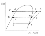
- FIG. 3 is a ph diagram of a refrigeration cycle when the air-conditioning apparatus 100 according to Embodiment 1 of the present invention is in a cooling only operation mode. It is a refrigerant circuit diagram which shows the flow of the heat-source side refrigerant
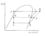
- FIG. 3 is a ph diagram of a refrigeration cycle when the air-conditioning apparatus 100 according to Embodiment 1 of the present invention is in a cooling only operation mode.
- FIG. 1 is a refrigerant circuit diagram which shows the flow of the heat-source side refrigerant
- FIG. 3 is a ph diagram of a refrigeration cycle when the air-conditioning apparatus 100 according to Embodiment 1 of the present invention is in a heating only operation mode. It is a refrigerant circuit diagram which shows the flow of the heat-source side refrigerant
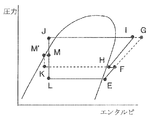
- FIG. 3 is a ph diagram of a refrigeration cycle when the air-conditioning apparatus 100 according to Embodiment 1 of the present invention is in a cooling main operation mode.
- FIG. 3 is a ph diagram of a refrigeration cycle when the air-conditioning apparatus 100 according to Embodiment 1 of the present invention is in a heating main operation mode.
- FIG. 3 is a structural diagram of the expansion device 14b (or the expansion device 14a) of the air-conditioning apparatus 100 according to Embodiment 1 of the present invention.
- FIG. 6 is a ph diagram of a refrigeration cycle when the air-conditioning apparatus 100 according to Embodiment 2 of the present invention is in a cooling only operation mode.
- FIG. 7 is a ph diagram of a refrigeration cycle when the air-conditioning apparatus 100 according to Embodiment 2 of the present invention is in a heating only operation mode. It is a refrigerant circuit diagram which shows the flow of the heat-source side refrigerant
- FIG. 7 is a ph diagram of a refrigeration cycle when the air-conditioning apparatus 100 according to Embodiment 2 of the present invention is in a heating only operation mode.
- FIG. 7 is a refrigerant circuit diagram which shows the flow of the heat-source side refrigerant
- FIG. 10 is a ph diagram of a refrigeration cycle when the air-conditioning apparatus 100 according to Embodiment 2 of the present invention is in a cooling main operation mode. It is a refrigerant circuit diagram which shows the flow of the heat-source side refrigerant
- FIG. 7 is a ph diagram of a refrigeration cycle when the air-conditioning apparatus 100 according to Embodiment 2 of the present invention is in a heating main operation mode. It is the schematic which shows an example of the circuit structure of the air conditioning apparatus 100a which concerns on Embodiment 3 of this invention. It is the schematic which shows an example of the circuit structure of the air conditioning apparatus 100b which concerns on Embodiment 4 of this invention.
- FIG. 1 is a schematic diagram illustrating an installation example of an air-conditioning apparatus according to Embodiment 1 of the present invention.
- each indoor unit is operated by using a refrigeration cycle (a refrigerant circulation circuit A and a heat medium circulation circuit B, which will be described later) in which a refrigerant (heat source side refrigerant and heat medium) circulates.
- a refrigerant heat source side refrigerant and heat medium
- a cooling operation or a heating operation can be freely selected as a mode.
- the air conditioner according to the present embodiment employs a method of indirectly using the heat source side refrigerant.
- the cold or warm heat stored in the heat source side refrigerant is transmitted to a heat medium that is a refrigerant different from the heat source side refrigerant, and the air-conditioning target space is cooled or heated by the cold heat or heat stored in the heat medium. It has become.
- the air conditioner according to the present embodiment includes a single outdoor unit 1 that is a heat source unit, a plurality of indoor units 2, and an outdoor unit 1 and an indoor unit 2. And a heat medium relay unit 3 interposed therebetween.
- the outdoor unit 1 and the heat medium relay unit 3 are connected by a refrigerant pipe 4 through which the heat source side refrigerant flows.
- the heat medium relay unit 3 and the indoor unit 2 are connected by a heat medium pipe 5 through which the heat medium flows.
- the cold or warm heat generated by the outdoor unit 1 is transmitted to the indoor unit 2 via the heat medium converter 3.
- the outdoor unit 1 is usually installed in an outdoor space 6 that is a space outside a building 9 such as a building (for example, a rooftop), and supplies cold or hot heat to the indoor unit 2 via the heat medium converter 3. It is.
- a building 9 for example, a rooftop
- the outdoor unit 1 may be installed in an enclosed space such as a machine room with a ventilation opening, and if the waste heat can be exhausted outside the building 9 by an exhaust duct, Alternatively, when the water-cooled outdoor unit 1 is used, it may be installed inside the building 9. Even if the outdoor unit 1 is installed in such a place, no particular problem occurs.
- the indoor unit 2 is disposed at a position where cooling air or heating air can be supplied to the indoor space 7 which is a space (for example, a living room) inside the building 9, and the cooling air is supplied to the indoor space 7 as the air-conditioning target space. Alternatively, heating air is supplied.
- FIG. 1 an example is shown in which the indoor unit 2 is a ceiling cassette type.
- the present invention is not limited to this, and the indoor unit 2 is not directly limited to the indoor space 7 such as a ceiling embedded type or a ceiling suspended type.
- any type of air can be used as long as heating air or cooling air can be blown out by a duct or the like.
- the heat medium relay unit 3 is configured as a separate housing from the outdoor unit 1 and the indoor unit 2 and is configured to be installed at a position different from the outdoor space 6 and the indoor space 7. Are connected by a refrigerant pipe 4 and a heat medium pipe 5, respectively.
- the heat medium relay unit 3 transmits cold heat or warm heat supplied from the outdoor unit 1 to the indoor unit 2. Specifically, heat exchange is performed between the heat source side refrigerant on the outdoor unit 1 side and the heat medium (for example, water or antifreeze liquid) on the indoor unit 2 side different from the heat source side refrigerant.
- FIG. 1 shows an example in which the heat medium converter 3 is installed in a space 8 such as the back of the ceiling, which is inside the building 9 but is different from the indoor space 7. Yes.
- the heat medium converter 3 is provided close to the indoor unit 2 installed in the indoor space 7, the piping of the circuit through which the heat medium circulates (heat medium circulation circuit B described later) can be shortened. it can. Thereby, the conveyance power of the heat medium in the heat medium circuit B can be reduced, and energy saving can be achieved.
- the heat medium relay unit 3 is installed in the space 8, but is not limited to this, and is installed in a common space with an elevator or the like, for example. It may be a thing.
- the heat medium relay unit 3 is provided close to the indoor unit 2, but is not limited thereto, and may be installed in the vicinity of the outdoor unit 1. . However, in this case, it should be noted that if the distance from the heat medium relay unit 3 to the indoor unit 2 is too long, the power for transporting the heat medium becomes considerably large, and the effect of energy saving is diminished.
- the refrigerant pipe 4 is composed of two pipes, and the outdoor unit 1 and the heat medium converter 3 are connected by the two refrigerant pipes 4. Further, the heat medium pipe 5 connects the heat medium converter 3 and each indoor unit 2, and the heat medium converter 3 and each indoor unit 2 are connected by two heat medium pipes 5.
- each unit (the outdoor unit 1, the indoor unit 2, and the heat medium converter 3) using two pipes (the refrigerant pipe 4 and the heat medium pipe 5). By connecting, construction is easy.
- the number of connected outdoor units 1, indoor units 2, and heat medium converters 3 is not limited to the number shown in FIG. 1 and FIG. 2, which will be described later, but the air conditioner according to the present embodiment.
- the number of units may be determined according to the building 9 in which is installed. Further, in the following drawings including FIG. 1, the relationship of the sizes of the constituent members is not limited to that shown in the drawings, and may differ from the actual ones.
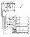
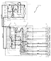
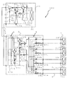
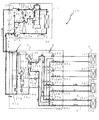
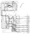
- FIG. 2 is a schematic diagram illustrating an example of a circuit configuration of the air-conditioning apparatus (hereinafter referred to as air-conditioning apparatus 100) according to Embodiment 1 of the present invention.
- air-conditioning apparatus 100 the air-conditioning apparatus 100 according to Embodiment 1 of the present invention.
- the detailed configuration of the air-conditioning apparatus 100 will be described with reference to FIG.
- the outdoor unit 1 and the heat medium converter 3 are connected by the two refrigerant pipes 4 as described above, and the refrigerant pipe 4 is a refrigerant pipe inside the heat medium converter 3.
- the refrigerant pipe 4 is a refrigerant pipe inside the heat medium converter 3.
- the above-described refrigerant circulation circuit A includes the refrigerant pipe 4 that connects the outdoor unit 1 and the heat medium converter 3, and includes the heat exchanger 15a between the heat medium and the heat medium in the heat medium converter 3.
- Each of the heat exchangers 15b is a refrigerant circuit configured by connecting each device with a refrigerant pipe through which a heat source side refrigerant that performs heat exchange with a heat medium flows.
- the refrigerant circuit A includes a compressor 10, a first refrigerant flow switching device 11, a heat source side heat exchanger 12, a gas-liquid separator 27a, an opening / closing device 17, an expansion device 16, and a heat medium, which will be described later.
- Refrigerant flow path of heat exchanger 15, second refrigerant flow switching device 18, gas-liquid separator 27b, accumulator 19, check valves 13a to 13d, expansion devices 14a and 14b, backflow prevention device 20, and opening / closing device 24 is connected and constituted by refrigerant piping. Details of the connection relationship of each of the above devices constituting the refrigerant circuit A will be described later.
- the heat medium relay unit 3 and the indoor unit 2 are connected by the two heat medium pipes 5 as described above, and the heat medium pipe 5 is connected to the heat medium pipe by the heat medium pipe inside the heat medium converter 3.
- the converter 3 is connected to each of the heat exchanger related to heat medium 15a and the heat exchanger related to heat medium 15b.
- the heat medium circulation circuit B described above includes the heat medium pipe 5 that connects the heat medium converter 3 and each indoor unit 2, and includes the heat exchanger 15 a between the heat medium and the heat in the heat medium converter 3.
- each of the heat exchangers between mediums 15b it refers to a heat medium circuit configured by connecting each device with a heat medium pipe through which a heat medium that performs heat exchange with the heat source side refrigerant flows.
- the heat medium circulation circuit B includes a heat medium flow path of the heat exchanger 15 between heat mediums, a pump 21 described later, a first heat medium flow switching device 22, a heat medium flow control device 25, and use side heat.
- the exchanger 26 and the second heat medium flow switching device 23 are connected and configured by a heat medium pipe.
- the heat medium circulating in the heat medium circuit B is not particularly limited.
- brine antifreeze
- water a mixed liquid of brine and water, or an additive having high water and anticorrosive effect What is necessary is just to use the liquid mixture with an agent.
- a highly safe heat medium is used, which improves safety. Will contribute. Details of the connection relationship of each of the above devices constituting the heat medium circuit B will be described later.
- the outdoor unit 1 and the heat medium converter 3 include the heat exchanger related to heat medium 15 a and the heat medium provided in the heat medium converter 3. It is connected via the intermediate heat exchanger 15b, and the heat medium relay unit 3 and the indoor unit 2 are also connected via the intermediate heat exchanger 15a and the intermediate heat exchanger 15b. That is, in the air conditioner 100, the heat source side refrigerant that circulates in the refrigerant circulation circuit A and the heat medium that circulates in the heat medium circulation circuit B in the heat exchanger related to heat medium 15a and the heat exchanger related to heat medium 15b generate heat. It is supposed to be replaced.
- the outdoor unit 1 includes a compressor 10, a first refrigerant flow switching device 11 such as a four-way valve, a heat source side heat exchanger 12, an accumulator 19, and gas-liquid separators 27a and 27b, which are connected in series. Connected to the refrigerant pipe.
- the outdoor unit 1 includes a first connection pipe 4a, a second connection pipe 4b, an injection pipe 4c, a branch pipe 4d, check valves 13a to 13d, throttling devices 14a and 14b, a backflow prevention device 20, a switching device 24, And the control apparatus 50 is provided.
- the outdoor unit 1 is provided with medium pressure detecting means 32, discharged refrigerant temperature detecting means 37, and high pressure detecting means 39 that are electrically connected to the control device 50.
- medium pressure detecting means 32 discharged refrigerant temperature detecting means 37
- high pressure detecting means 39 that are electrically connected to the control device 50.
- the compressor 10 sucks the heat source side refrigerant in a gas state and compresses the heat source side refrigerant to be in a high temperature and high pressure state.
- the compressor 10 is constituted by an inverter compressor or the like capable of capacity control. Good.
- the compressor 10 has a compression chamber in a sealed container, the inside of the sealed container has a low-pressure refrigerant pressure atmosphere, and has a low-pressure shell structure that sucks and compresses the low-pressure refrigerant in the sealed container in the compression chamber. .
- An opening is provided in a part of the compression chamber of the compressor 10, and the heat source side refrigerant is introduced (injected) into the compressor 10 through the opening from the outside of the sealed container.
- an injection pipe 4c is connected. When the rotation angle of the motor of the compressor 10 becomes a certain angle, the opening is opened, and the inside of the compression chamber and the injection pipe 4c are communicated with each other.
- the first refrigerant flow switching device 11 is in the flow of the heat source side refrigerant in the heating operation (the heating only operation mode and the heating main operation mode described later) and in the cooling operation (the cooling only operation mode and the cooling main operation mode described later). The flow of the heat source side refrigerant is switched.
- the heat source side heat exchanger 12 functions as an evaporator during heating operation, functions as a condenser (or radiator) during cooling operation, and between the air supplied from a blower (not shown) and the heat source side refrigerant. Heat exchange is performed.
- the accumulator 19 is provided on the suction side of the compressor 10 and is used for surplus refrigerant due to a difference between the heating operation and the cooling operation and a change in transient operation (for example, a change in the number of indoor units 2 operated).
- the excess refrigerant is stored.
- the first connection pipe 4 a includes a refrigerant pipe that connects the first refrigerant flow switching device 11 and a check valve 13 d described later, a gas-liquid separator 27 a and a check valve 13 a described later.
- the refrigerant pipe to be connected is connected.
- the second connection pipe 4b connects a refrigerant pipe that connects a gas-liquid separator 27b and a check valve 13d, which will be described later, and a heat source side heat exchanger 12 and a check valve 13a, which will be described later.
- the refrigerant pipe is connected.
- the injection pipe 4c connects a pipe between a backflow prevention device 20 and a switching device 24 installed in a branch pipe 4d, which will be described later, and an opening for injecting a heat source side refrigerant into the compressor 10. is there.
- the branch pipe 4d is a refrigerant pipe that connects a gas-liquid separator 27a and a gas-liquid separator 27b described later, and a backflow prevention device 20 and an opening / closing device 24 described later are installed from the gas-liquid separator 27b side.
- the check valve 13a is provided in a refrigerant pipe that connects the heat source side heat exchanger 12 and a gas-liquid separator 27a, which will be described later, and supplies the refrigerant only in the direction from the heat source side heat exchanger 12 to the gas-liquid separator 27a. It is to be distributed.
- the check valve 13b is provided in the first connection pipe 4a, and causes the heat-source-side refrigerant discharged from the compressor 10 to flow only in the direction toward the heat medium converter 3 during the heating operation.
- the check valve 13c is provided in the second connection pipe 4b and allows the refrigerant returned from the heat medium relay unit 3 to flow only in the direction toward the heat source side heat exchanger 12 during the heating operation.
- the check valve 13d is provided in a refrigerant pipe connecting the first refrigerant flow switching device 11 and a gas-liquid separator 27b described later, and the direction from the gas-liquid separator 27b to the first refrigerant flow switching device 11 is provided. Only the refrigerant is circulated.
- the expansion device 14a is installed in the second connection pipe 4b, and expands and depressurizes the heat source side refrigerant flowing into the outdoor unit 1 from the heat medium relay unit 3 during heating operation.
- the expansion device 14b is an electronic expansion valve or the like whose opening area can be changed, and is installed in the injection pipe 4c to expand and depressurize the medium-pressure two-phase refrigerant.
- the backflow prevention device 20 is installed in a branch pipe 4d between a gas-liquid separator 27b and an opening / closing device 24, which will be described later, and the heat-source-side refrigerant separated by the gas-liquid separator 27b during the heating operation is The heat-source-side refrigerant is conducted only in the direction from the separator 27b toward the compressor 10.
- the opening / closing device 24 is installed in a branch pipe 4d between a gas-liquid separator 27a and a backflow prevention device 20, which will be described later, and is a heat source that is opened during cooling operation and separated by the gas-liquid separator 27a.
- the side refrigerant is conducted to the injection pipe 4c.
- the gas-liquid separator 27a is installed in a refrigerant pipe between the check valve 13a and the refrigerant pipe 4 that allows the heat-source-side refrigerant to flow out of the outdoor unit 1, and via the gas-liquid separator 27b and the branch pipe 4d. It is connected.
- the gas-liquid separator 27a branches the high-pressure refrigerant flowing out from the heat source side heat exchanger 12 into one that flows into the branch pipe 4d and one that flows out from the outdoor unit 1 during the cooling operation.
- the gas-liquid separator 27b is installed in the refrigerant pipe between the refrigerant pipe 4 for allowing the heat source side refrigerant to flow into the outdoor unit 1 and the check valve 13d, and also via the gas-liquid separator 27a and the branch pipe 4d. It is connected.
- This gas-liquid separator 27b branches into one that causes the refrigerant flowing into the outdoor unit 1 to flow into the branch pipe 4d and one that sends it to the heat source side heat exchanger 12 side during heating operation. is there.
- the medium pressure detecting means 32 is installed in the refrigerant pipe on the outlet side facing the second connection pipe 4b side of the gas-liquid separator 27b, and the pressure of the medium-pressure refrigerant flowing out from the gas-liquid separator 27b during the heating operation. Is detected.
- the discharge refrigerant temperature detection means 37 is installed in the refrigerant pipe on the discharge port side of the compressor 10 and detects the temperature (discharge temperature) of the heat source side refrigerant discharged from the compressor 10.
- the high pressure detection means 39 is installed in the refrigerant piping on the discharge port side of the compressor 10 and detects the pressure (discharge pressure) of the heat source side refrigerant discharged from the compressor 10.
- the medium pressure detection unit 32, the discharge refrigerant temperature detection unit 37, and the high pressure detection unit 39 transmit detection information to the control device 50.
- the control device 50 is configured by a microcomputer or the like, and controls the entire air conditioner 100 based on detection information from various detection means and operation information from a remote controller.
- the driving frequency of the compressor 10 the rotational speed of the blower provided in the heat source side heat exchanger 12 (including ON / OFF operation), switching of the refrigerant flow path of the first refrigerant flow switching device 11, and the opening / closing device 24 Open / close control and control of each operation mode to be described later.
- the first refrigerant flow switching device 11, the heat source side heat exchanger 12, the expansion device 14a, and the expansion device 14b are respectively the “refrigerant flow switching device”, “first heat exchanger”, “third” of the present invention. It corresponds to “aperture device” and “second aperture device”.
- the backflow prevention device 20 and the opening / closing device 24 correspond to the “second conduction means” and the “first conduction means” of the present invention, respectively.
- Each indoor unit 2 includes a use side heat exchanger 26.
- the four indoor units 2 shown in FIG. 2 are referred to as an indoor unit 2a, an indoor unit 2b, an indoor unit 2c, and an indoor unit 2d from the bottom in FIG. It is simply referred to as indoor unit 2.
- the four usage-side heat exchangers 26 shown in FIG. 2 are connected to the usage-side heat exchanger 26a, the usage-side heat exchanger 26b, and the usage-side heat from the bottom in FIG. 2 according to the indoor units 2a to 2d.
- the exchanger 26c and the user-side heat exchanger 26d are simply referred to as the user-side heat exchanger 26 when shown without distinction.
- the use side heat exchangers 26 are respectively connected to the heat medium pipe 5 through which the heat medium flowing out from the heat medium converter 3 flows and the heat medium pipe 5 through which the heat medium flowing out from the indoor unit 2 are circulated by the heat medium pipe. It is connected. Further, the use-side heat exchanger 26 functions as a condenser (or a radiator) during heating operation, functions as an evaporator during cooling operation, and is used between indoor air and a heat medium supplied from a blower (not shown). Heat exchange is performed between them, and heating air or cooling air to be supplied to the indoor space 7 is generated.
- the number of indoor units 2 connected is not limited to the four shown in FIG. 2, and may be one or more.
- the heat medium relay unit 3 includes two heat exchangers 15 between heat mediums 15, two expansion devices 16, two switching devices 17, two second refrigerant flow switching devices 18, two pumps 21, and four first heats.
- a medium flow switching device 22, four second heat medium flow switching devices 23, and four heat medium flow control devices 25 are provided.
- the two heat exchangers between heat mediums 15 function as condensers (or radiators) or evaporators, perform heat exchange between the heat source side refrigerant and the heat medium, and are generated by the outdoor unit 1, and are generated on the heat source side.
- the cold or warm heat stored in the refrigerant is transmitted to the heat medium.
- the two intermediate heat exchangers 15 shown in FIG. 2 are referred to as an intermediate heat exchanger 15a and an intermediate heat exchanger 15b, respectively.
- the heat exchanger 15 is assumed to be.
- the heat exchanger related to heat medium 15a is provided between the expansion device 16a and the second refrigerant flow switching device 18a in the refrigerant circuit A, and heats the heat medium in the heating only operation mode described later.
- the heat medium is used for cooling.
- the heat exchanger related to heat medium 15b is provided between the expansion device 16b and the second refrigerant flow switching device 18b in the refrigerant circuit A, and cools the heat medium in the cooling only operation mode described later.
- the heating medium is used for heating.
- the two expansion devices 16 have a function as a pressure reducing / expanding valve in the refrigerant circulation circuit A, and expand and depressurize the heat source side refrigerant.
- the two diaphragm devices 16 shown in FIG. 2 are referred to as a diaphragm device 16a and a diaphragm device 16b, respectively.
- the expansion device 16a is connected to the heat exchanger related to heat medium 15a so that one of the expansion devices 16a is upstream of the heat exchanger related to heat medium 15a in the flow of the heat source side refrigerant in the cooling only operation mode, and the other is opened and closed. It is connected to the device 17a.
- the expansion device 16b is connected to the heat exchanger related to heat medium 15b so that one of the expansion devices 16b is upstream of the heat exchanger related to heat medium 15b in the flow of the heat source side refrigerant in the cooling only operation mode, and the other is the switchgear. 17a.
- the expansion device 16 may be configured by a device whose opening degree (opening area) can be variably controlled, for example, an electronic expansion valve or the like.
- the two opening / closing devices 17 are constituted by a two-way valve or the like, and open / close the refrigerant piping in the refrigerant circulation circuit A.
- the two opening / closing devices 17 shown in FIG. 2 are referred to as an opening / closing device 17a and an opening / closing device 17b, respectively.
- one of the opening / closing devices 17a is connected to the refrigerant pipe 4 through which the heat source side refrigerant flows into the heat medium relay unit 3, and the other is connected to the expansion devices 16a and 16b.
- One of the opening / closing devices 17b is connected to the refrigerant pipe 4 through which the heat source side refrigerant flows out from the heat medium relay 3, and the other is connected to the side of the connection port of the opening / closing device 17a to which the expansion device 16 is connected. Yes.
- the two second refrigerant flow switching devices 18 are constituted by a four-way valve or the like, and in the refrigerant circulation circuit A, the flow of the heat source side refrigerant is switched according to the operation mode.
- the two second refrigerant flow switching devices 18 shown in FIG. 2 are respectively referred to as the second refrigerant flow switching device 18a and the second refrigerant flow switching device 18b without distinction, It is simply referred to as the second refrigerant flow switching device 18.
- the second refrigerant flow switching device 18a is provided on the downstream side of the heat exchanger related to heat medium 15a in the flow of the heat source side refrigerant in the cooling only operation mode.
- the second refrigerant flow switching device 18b is provided on the downstream side of the heat exchanger related to heat medium 15b in the flow of the heat source side refrigerant in the cooling only operation mode.
- the two pumps 21 are configured to pump and circulate the heat medium in the heat medium circuit B.
- the two pumps 21 shown in FIG. 2 are referred to as a pump 21a and a pump 21b, respectively.
- the pump 21 a is provided in a heat medium pipe between the heat exchanger related to heat medium 15 a and the second heat medium flow switching device 23.
- the pump 21 b is provided in the heat medium pipe between the heat exchanger related to heat medium 15 b and the second heat medium flow switching device 23.
- the pump 21 may be constituted by a pump whose capacity can be controlled, for example.
- the pump 21a may be provided in a heat medium pipe between the heat exchanger related to heat medium 15a and the first heat medium flow switching device 22.
- the pump 21b may be provided in a heat medium pipe between the heat exchanger related to heat medium 15b and the first heat medium flow switching device 22.
- the four first heat medium flow switching devices 22 are configured by a three-way valve or the like, and in the heat medium circulation circuit B, switch the heat medium flow path according to the operation mode.
- the four first heat medium flow switching devices 22 shown in FIG. 2 are divided into the first heat medium flow switching device 22a, the first heat according to the indoor units 2a to 2d from the bottom in FIG.
- the medium flow path switching device 22b, the first heat medium flow path switching device 22c, and the first heat medium flow path switching device 22d are simply referred to as the first heat medium flow path switching device 22 when shown without distinction. Let's say.
- the number of first heat medium flow switching devices 22 is set according to the number of indoor units 2 installed (four in FIG. 2).
- the first heat medium flow switching device 22 includes one of the three heat transfer medium heat exchangers 15a, the other heat transfer medium heat exchanger 15b, and the other heat medium flow rate adjustment.
- the heat medium that is connected to each of the devices 25 and flows out from the use side heat exchanger 26 flows in through the heat medium pipe 5 and the heat medium flow control device 25.
- the four second heat medium flow switching devices 23 are configured by a three-way valve or the like, and in the heat medium circulation circuit B, switch the heat medium flow path according to the operation mode.
- the four second heat medium flow switching devices 23 shown in FIG. 2 are divided into the second heat medium flow switching devices 23a, the second heat from the bottom in FIG. 2 according to the indoor units 2a to 2d.
- the medium flow path switching device 23b, the second heat medium flow path switching device 23c, and the second heat medium flow path switching device 23d are simply referred to as the second heat medium flow path switching device 23 in the case where they are shown without distinction. Let's say.
- the number of the second heat medium flow switching devices 23 is set according to the number of indoor units 2 installed (four in FIG. 2).
- the second heat medium flow switching device 23 has one of the three sides to the pump 21a, the other to the pump 21b, and the other to the use side heat exchanger 26 via the heat medium pipe 5. , Each connected.
- the heat medium flow control device 25 is configured by a two-way valve or the like that can control the opening area. To do.
- the four heat medium flow control devices 25 shown in FIG. 2 are divided into the heat medium flow control device 25a, the heat medium flow control device 25b, and the heat medium from the bottom in FIG. 2 according to the indoor units 2a to 2d.
- the flow rate adjusting device 25c and the heat medium flow rate adjusting device 25d are referred to as the heat medium flow rate adjusting device 25, respectively.
- the number of heat medium flow control devices 25 (four in FIG. 2) according to the number of indoor units 2 installed is provided.
- one of the heat medium flow control devices 25 is the heat medium pipe 5 through which the heat medium flowing out from the use side heat exchanger 26 of the indoor unit 2 flows into the heat medium converter 3, and the other is the first heat medium flow path.
- the heat medium flow control device 25 is installed in the heat medium piping system on the outlet side of the heat medium flow path of the use side heat exchanger 26 as described above, but is not limited to this.
- Heat medium piping system on the inlet side of the side heat exchanger 26 (for example, the second heat medium flow switching device 23 and the heat medium flowing out of the heat medium converter 3 flows into the use side heat exchanger 26 of the indoor unit 2) It is good also as what is installed between the heat-medium piping 5 to be made.
- the heat exchanger 3 also includes two heat exchanger heat exchanger outlet temperature detection means 31, four heat exchanger outlet temperature detection means 34, and four heat exchanger heat exchanger refrigerant temperature detection means 35. , And two heat medium heat exchanger refrigerant pressure detection means 36 are provided. Information (temperature information and pressure information) detected by these detection means is transmitted to a control device (not shown) installed in the heat medium relay unit 3.
- the control device is configured by a microcomputer or the like, and based on these detection information and operation information from a remote controller or the like, the rotational speed (ON / OFF) of a blower (not shown) provided in the use side heat exchanger 26 Operation), switching of the heat medium flow path of the second refrigerant flow switching device 18, driving frequency of the pump 21, heat medium flow of the first heat medium flow switching device 22 and the second heat medium flow switching device 23 The switching of the path and the heat medium flow rate of the heat medium flow control device 25 are controlled. Further, the control device controls the heat medium flow path of the first heat medium flow switching device 22 and the second heat medium flow switching device 23, thereby using the heat medium from the heat exchangers between heat mediums 15a on the use side.
- the control device controls the heat medium flow paths of the first heat medium flow switching device 22 and the second heat medium flow switching device 23, thereby allowing the inflow side flow path and the outflow side of the use side heat exchanger 26.
- the flow path can be selectively communicated between the heat exchanger related to heat medium 15a and the heat exchanger related to heat medium 15b.
- control apparatus shall be installed in the heat medium converter 3, it is not limited to this,
- the control apparatus 50 installed in the outdoor unit 1 may be substituted, or
- the control device and the control device 50 may be connected by a wired or wireless communication line and communicate with each other.
- the two intermediate heat exchanger outlet temperature detecting means 31 detects the heat medium flowing out from the intermediate heat exchanger 15, that is, the temperature of the heat medium on the outlet side of the intermediate heat exchanger 15.
- a thermistor or the like may be used.
- the two intermediate heat exchanger outlet temperature detection means 31 shown in FIG. 2 comprises an intermediate heat exchanger outlet temperature detection means 31a and an intermediate heat exchanger outlet temperature detection means 31b, respectively.
- the intermediate heat exchanger outlet temperature detection means 31 When showing without distinction, it is simply referred to as the intermediate heat exchanger outlet temperature detection means 31.
- the heat exchanger related to heat medium outlet temperature detection means 31a is provided in the heat medium pipe on the inlet side of the pump 21a.
- the heat exchanger related to heat medium outlet temperature detecting means 31b is provided in the heat medium pipe on the inlet side of the pump 21b.
- the four use side heat exchanger outlet temperature detection means 34 are provided between the first heat medium flow switching device 22 and the heat medium flow control device 25, and the temperature of the heat medium flowing out from the use side heat exchanger 26.
- a thermistor or the like may be used.
- the four utilization side heat exchanger outlet temperature detection means 34 shown in FIG. 2 are used from the bottom in FIG. 2 according to the indoor units 2a to 2d.
- the side heat exchanger outlet temperature detection means 34b, the usage side heat exchanger outlet temperature detection means 34c, and the usage side heat exchanger outlet temperature detection means 34d are referred to as “use side heat exchange”. It is assumed that the outlet temperature detecting means 34 is used.
- the use side heat exchanger outlet temperature detection means 34 is provided in a number (four in FIG. 2) corresponding to the number of indoor units 2 installed.
- the heat exchanger related to heat medium refrigerant temperature detecting means 35a and the heat exchanger related to heat medium refrigerant temperature detecting means 35c are installed between the heat exchanger related to heat medium 15 and the second refrigerant flow switching device 18, respectively.
- the temperature of the refrigerant flowing in or out of the heat exchanger related to heat medium 15 is detected, and for example, it may be constituted by a thermistor or the like.
- the heat exchanger related to heat medium refrigerant temperature detecting means 35b and the heat exchanger related to heat medium refrigerant temperature detecting means 35d are installed between the heat exchanger related to heat medium 15 and the expansion device 16, respectively.
- the temperature of the refrigerant flowing in or out of the heat exchanger 15 is detected, and for example, it may be constituted by a thermistor or the like.
- the exchanger refrigerant temperature detecting means 35d is shown without distinction, it is simply referred to as an intermediate heat exchanger refrigerant temperature detecting means 35.
- the heat exchanger related to heat medium refrigerant temperature detecting means 35a is provided between the heat exchanger related to heat medium 15a and the second refrigerant flow switching device 18a.
- the heat exchanger related to heat medium refrigerant temperature detecting means 35b is provided between the heat exchanger related to heat medium 15a and the expansion device 16a.
- the heat exchanger related to heat medium refrigerant temperature detecting means 35c is provided between the heat exchanger related to heat medium 15b and the second refrigerant flow switching device 18b.
- the intermediate heat exchanger refrigerant temperature detecting means 35d is provided between the intermediate heat exchanger 15b and the expansion device 16b.
- the heat exchanger related to heat medium refrigerant pressure detecting means 36a is located between the heat exchanger related to heat medium 15a and the second refrigerant flow switching device 18a in the same manner as the installation position of the heat exchanger related to heat medium refrigerant temperature detecting means 35a. And detects the pressure of the refrigerant flowing between the heat exchanger related to heat medium 15a and the second refrigerant flow switching device 18a.
- the heat exchanger related to heat medium refrigerant pressure detecting means 36b is provided between the heat exchanger related to heat medium 15b and the expansion device 16b in the same manner as the installation position of the heat exchanger related to heat medium refrigerant temperature detecting means 35d. The pressure of the refrigerant flowing between the inter-medium heat exchanger 15b and the expansion device 16b is detected.
- the heat exchanger related to heat medium 15 and the expansion device 16 correspond to the “second heat exchanger” and the “first expansion device” of the present invention, respectively.
- the air conditioner 100 performs an injection operation by the injection pipe 4c as a means for lowering the discharge temperature of the compressor 10 in the outdoor unit 1 as described above.
- an opening is provided in a part of the compression chamber of the compressor 10, and further, from the outside of the sealed container to the inside of the compression chamber of the compressor 10 through the opening.
- An injection pipe 4c for introducing the heat source side refrigerant is provided, and the heat source side refrigerant is injected from the injection pipe 4c into the compression chamber through the opening.
- the discharge temperature of the compressor 10 or the superheat degree (discharge superheat) of the refrigerant discharged from the compressor 10 can be reduced, and the control device 50 can open and close the opening / closing device 24, the expansion device 14a, and the expansion device 14b.
- the control device 50 can open and close the opening / closing device 24, the expansion device 14a, and the expansion device 14b.
- the difference in discharge temperature between when R410A or the like is used as a refrigerant and when R32 or the like is used will be briefly described.
- the evaporation temperature of the refrigeration cycle of the air conditioner 100 is 0 ° C.
- the condensation temperature is 49 ° C.
- the superheat (superheat degree) of the refrigerant sucked in the compressor 10 is 0 ° C.
- the discharge temperature of the compressor 10 is about 70 ° C. due to the physical properties of the heat source side refrigerant.
- the discharge temperature of the compressor 10 is about 86 ° C. due to the physical properties of the heat source side refrigerant. That is, when R32 is used as the heat source side refrigerant, the discharge temperature increases by about 16 ° C. compared to when R410A is used.
- the compressor 10 performs polytropic compression, which is an operation that is less efficient than adiabatic compression, and thus the discharge temperature becomes higher than the above-described value. Even when R410A is used, it is frequently generated that the discharge temperature exceeds 100 ° C. Under the conditions where the discharge temperature exceeds 104 ° C. in R410A, the discharge temperature needs to be lowered because R32 exceeds the upper limit of 120 ° C. in R32.
- the compressor 10 uses a high-pressure shell structure in which the suction refrigerant is directly sucked into the compression chamber and the heat source side refrigerant discharged from the compression chamber is discharged into a sealed container around the compression chamber,
- the discharge temperature can be lowered by moistening the suction refrigerant from the saturated state and sucking the two-phase heat source side refrigerant into the compression chamber of the compressor 10.
- a compressor 10 having a low-pressure shell structure even if the sucked refrigerant is moistened, the liquid refrigerant only accumulates in the shell of the compressor 10 and the gas-liquid two-phase is stored in the compression chamber. The refrigerant is not inhaled.
- the compressor 10 having a low-pressure shell structure is used and R32 or the like whose discharge temperature is high is used, in order to lower the discharge temperature, the compression chamber of the compressor 10 is compressed from the outside.
- a method of injecting a low-temperature refrigerant and reducing the temperature of the heat source side refrigerant is effective. Therefore, the discharge temperature may be lowered by the injection operation as described above.
- the discharge temperature detected by the discharge refrigerant temperature detection means 37 is made into target value (for example, 100 degreeC).
- the target value may be changed in accordance with the outside air temperature.
- the injection flow rate is increased or decreased by adjusting the opening (opening area) of the expansion device 14b by the control device 50.
- the control method of the injection amount by the control device 50 is not limited to the above, and the discharge temperature detected by the discharge refrigerant temperature detection means 37 is likely to exceed a target value (for example, 110 ° C.). It may be controlled so that the injection is not performed and the injection is not performed.
- control device 50 performs control so that the discharge temperature detected by the discharge refrigerant temperature detection means 37 falls within a target range (for example, 80 ° C. to 100 ° C.), and the discharge temperature is likely to exceed the upper limit of the target range.
- a target range for example, 80 ° C. to 100 ° C.
- the injection amount may be increased, and control may be performed to decrease the injection amount when the discharge temperature is likely to fall below the lower limit of the target range.
- the above-described injection amount control is such that the discharge temperature falls within the target value or target range, but the discharge superheat (discharge superheat degree) falls within the target value or target range. It may be a thing.
- the control device 50 calculates the discharge superheat (discharge superheat degree) based on the discharge temperature detected by the discharge refrigerant temperature detection means 37 and the discharge pressure detected by the high pressure detection means 39, and this discharge The injection amount may be controlled so that the superheat reaches a target value (for example, 30 ° C.), and the target value may be changed according to the outside air temperature.
- a target value for example, 30 ° C.
- control method of the injection amount by the control device 50 is not limited to the above-described one, and the injection is performed when the calculated discharge superheat is likely to exceed a target value (for example, 40 ° C.). In some cases, it may be controlled not to perform injection.
- the control device 50 controls the calculated discharge superheat so that it falls within the target range (for example, 10 ° C. to 40 ° C.). If the discharge superheat is likely to exceed the upper limit of the target range, the injection amount is increased. The injection amount may be controlled to decrease when the discharge superheat is likely to fall below the lower limit of the target range.
- any heat source side refrigerant whose discharge temperature is higher than R410A can reduce the discharge temperature by the configuration according to the present embodiment, and the same effect Play.
- a heat source side refrigerant that is 3 ° C. or higher than R410A is more effective.
- the discharge temperature is estimated by the same method as described above.
- the discharge temperature is about 70 ° C., which is almost the same as that of R410A.
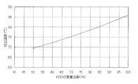
- the mass ratio of R32 is 43%, the temperature is about 73 ° C., 3 ° C. higher than the discharge temperature of R410A. I know it will be.
- the mixed refrigerant of R32 and HFO1234ze when a mixed refrigerant having a mass ratio of R32 of near 43% or more is used, if the discharge temperature is lowered by the injection operation, the effect is great.
- the refrigerant type in the mixed refrigerant is not limited to the above, and even a mixed refrigerant containing a small amount of other refrigerant components does not have a significant effect on the discharge temperature and has the same effect. .
- it can be used in a mixed refrigerant containing a small amount of other refrigerant in the mixed refrigerant of R32 and HFO1234yf.
- the air conditioner 100 can select a cooling operation or a heating operation in the indoor unit 2 based on an instruction from each indoor unit 2. That is, the air conditioner 100 can perform the same operation in all of the indoor units 2 and can perform different operations in each of the indoor units 2.
- a cooling only operation mode in which all the driven indoor units 2 perform a cooling operation As an operation mode performed by the air conditioner 100, a cooling only operation mode in which all the driven indoor units 2 perform a cooling operation, and a heating only operation mode in which all the driven indoor units 2 perform a heating operation. There are a cooling main operation mode in which the cooling load is larger and a heating main operation mode in which the heating load is larger. Below, each operation mode is demonstrated with the flow of a heat-source side refrigerant
- the pressure loss (the heat-source-side refrigerant flows through the narrow flow path in the compression chamber opening, and A pressure loss occurs due to the sudden expansion or contraction of the flow.
- the presence or absence of this pressure loss does not affect the effect of this embodiment, and in order to make the operation easy to understand, in the following description, the pressure loss at this opening is ignored (not assumed). ing.
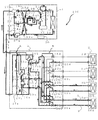
- FIG. 4 is a refrigerant circuit diagram showing the flow of the heat source side refrigerant and the heat medium when the air-conditioning apparatus 100 according to Embodiment 1 of the present invention is in the cooling only operation mode
- FIG. FIG. 3 is a ph diagram of a refrigeration cycle in a cooling only operation mode.
- the cooling only operation mode will be described by taking as an example a case where a cooling load is generated only in the use side heat exchanger 26a and the use side heat exchanger 26b.
- FIG. 4 the cooling only operation mode will be described by taking as an example a case where a cooling load is generated only in the use side heat exchanger 26a and the use side heat exchanger 26b.
- pipes represented by bold lines indicate pipes through which the heat source side refrigerant and the heat medium flow, and the direction in which the heat source side refrigerant flows is indicated by a solid line arrow, and the direction in which the heat medium flows is indicated by a broken line arrow. Yes.
- the control device 50 supplies the heat source side refrigerant discharged from the compressor 10 to the heat source side heat exchanger with respect to the first refrigerant flow switching device 11.
- the refrigerant flow path is switched so as to flow into 12.
- the control device 50 performs opening / closing control so that the opening / closing device 17a is in the open state, the opening / closing device 17b is in the closed state, and the opening / closing device 24 is in the open state.
- the control apparatus 50 drives the pump 21a and the pump 21b in the heat medium converter 3, opens the heat medium flow control device 25a and the heat medium flow control device 25b, and opens the heat medium flow control device 25c and the heat medium flow rate.
- the adjusting device 25d is fully closed so that the heat medium circulates between the heat exchanger related to heat medium 15a and the heat exchanger related to heat medium 15b, and the use side heat exchanger 26a and the use side heat exchanger 26b. I have to.
- a low-temperature and low-pressure gas refrigerant (point E) is compressed by the compressor 10 and discharged as a high-temperature and high-pressure gas refrigerant (point I), and passes through the first refrigerant flow switching device 11 to be a heat source side heat exchanger. 12 flows into the outdoor air and condenses while dissipating heat, and becomes a high-pressure liquid refrigerant.
- part of the high-pressure liquid refrigerant that has flowed into the gas-liquid separator 27a branches to the branch pipe 4d, passes through the opening / closing device 24, then flows into the injection pipe 4c, and is expanded and depressurized by the expansion device 14b. Then, it becomes a gas-liquid two-phase refrigerant at low temperature and intermediate pressure (point K), and is injected into the compressor 10 from the opening provided in the compression chamber of the compressor 10.
- the medium-pressure gas refrigerant (point F) and the low-temperature medium-pressure gas-liquid two-phase refrigerant (point K) are mixed, and the temperature of the heat source side refrigerant decreases (point H).
- the discharge temperature of the gas refrigerant discharged from the compressor 10 decreases (point I). Further, the discharge temperature of the compressor 10 when the injection operation is not performed is the point G in FIG. 5, and it can be seen that the discharge temperature is lowered from the point G to the point I by the injection operation.
- the high-pressure liquid refrigerant that has flowed into the heat medium relay unit 3 passes through the opening / closing device 17a, and then branches, flows into the expansion device 16a and the expansion device 16b, is expanded and depressurized, and is a low-temperature and low-pressure gas-liquid two-phase refrigerant.
- Point L This gas-liquid two-phase refrigerant flows into each of the heat exchanger related to heat medium 15a and the heat exchanger related to heat medium 15b acting as an evaporator and absorbs heat from the heat medium circulating in the heat medium circuit B to generate heat.
- the medium evaporates while cooling, and becomes a low-temperature and low-pressure gas refrigerant (point E).
- the gas refrigerant that has flowed out of the heat exchanger related to heat medium 15a and the heat exchanger related to heat medium 15b merges via the second refrigerant flow switching device 18a and the second refrigerant flow switching device 18b, respectively. It flows out of the unit 3, passes through the refrigerant pipe 4, and flows into the outdoor unit 1 again.
- the gas refrigerant that has flowed into the outdoor unit 1 is again sucked into the compressor 10 via the first refrigerant flow switching device 11 and the accumulator 19 through the gas-liquid separator 27b and the check valve 13d.
- the control device 50 detects, with respect to the expansion device 16a, the temperature detected by the intermediate heat exchanger refrigerant temperature detection means 35a and the temperature detected by the intermediate heat exchanger refrigerant temperature detection means 35b.
- the degree of opening is controlled so that the superheat (degree of superheat) obtained as the difference between the two becomes constant.
- the control device 50 detects, with respect to the expansion device 16b, the temperature detected by the intermediate heat exchanger refrigerant temperature detection means 35c and the temperature detected by the intermediate heat exchanger refrigerant temperature detection means 35d.
- the opening degree is controlled so that the superheat obtained as a difference between the two becomes constant.
- the expansion device 14b can change the opening area of an electronic expansion valve or the like, and the control device 50 can prevent the discharge temperature detected by the discharge refrigerant temperature detection means 37 from becoming too high.
- the injection flow rate is controlled by controlling the opening area.
- the control method is as described above.
- the expansion device 14b can change the opening area of an electronic expansion valve or the like.
- the expansion device 14b is not limited to this, and a capillary tube is used to inject a heat source side refrigerant in an amount corresponding to the pressure difference. You may make it do.
- the control of the expansion device 14b can be similarly applied in other operation modes.
- the heat source side refrigerant in the flow path from the opening / closing device 24 of the branch pipe 4d to the backflow prevention device 20 is a high-pressure refrigerant, and returns to the outdoor unit 1 from the heat medium converter 3 via the refrigerant pipe 4,
- the heat source side refrigerant reaching the separator 27b is a low pressure refrigerant.
- the backflow prevention device 20 prevents the high-pressure refrigerant branched from the gas-liquid separator 27a from flowing to the gas-liquid separator 27b.
- the high-pressure refrigerant in the branch pipe 4d Prevents mixing with the low-pressure refrigerant of the gas-liquid separator 27b.
- the backflow prevention device 20 may be a check valve, or a solenoid valve or the like that can be switched open or closed, or an electronic expansion valve or the like that changes the opening area and the refrigerant flow path can be switched between open and closed. do it.
- the opening / closing device 24a may be one that can change the opening area of an electronic expansion valve, etc., as well as one that can switch opening and closing of a solenoid valve, etc.
- the cold heat of the heat source side refrigerant is transmitted to the heat medium in both the heat exchanger 15a and the heat exchanger 15b, and the cooled heat medium is heated by the pump 21a and the pump 21b. It circulates in the medium circulation circuit B.
- the heat medium pressurized and discharged by the pump 21a and the pump 21b flows out of the heat medium converter 3 via the second heat medium flow switching device 23a and the second heat medium flow switching device 23b, and the heat medium It flows into the indoor unit 2a and the indoor unit 2b through the pipe 5, respectively.
- the heat medium flow control device 25c and the heat medium flow control device 25d are in a fully closed state, the heat medium passes through the second heat medium flow switching device 23c and the second heat medium flow switching device 23d. Therefore, the air does not flow into the indoor unit 2c and the indoor unit 2d, respectively.
- the heat medium flowing into the indoor unit 2a and the indoor unit 2b flows into the use side heat exchanger 26a and the use side heat exchanger 26b, respectively. Then, the heat medium flowing into the use side heat exchanger 26a and the use side heat exchanger 26b absorbs heat from the indoor air, whereby the cooling operation of the indoor space 7 is performed. And the heat medium which flowed out from the use side heat exchanger 26a and the use side heat exchanger 26b flows out from the indoor unit 2a and the indoor unit 2b, respectively, flows into the heat medium converter 3 through the heat medium pipe 5. .
- the heat medium flowing into the heat medium converter 3 flows into the heat medium flow control device 25a and the heat medium flow control device 25b.
- the heat medium flow rate adjusting device 25a and the heat medium flow rate adjusting device 25b control the flow rate of the heat medium to a flow rate necessary to cover the air conditioning load required in the room. It flows into the use side heat exchanger 26b.
- the heat medium that has flowed out of the heat medium flow control device 25a flows into the heat exchanger related to heat medium 15a and the heat exchanger related to heat medium 15b, respectively, via the first heat medium flow switching device 22a.
- the heat medium flowing out from the heat medium flow control device 25b flows into the heat exchanger related to heat medium 15a and the heat exchanger related to heat medium 15b via the first heat medium flow switching device 22b.
- the heat medium flowing into the heat exchanger related to heat medium 15a and the heat exchanger related to heat medium 15b is again sucked into the pump 21a and the pump 21b, respectively.
- the first heat medium flow switching device 22a and the first heat medium flow switching device 22b ensure a flow path that flows to both the heat exchanger related to heat medium 15a and the heat exchanger related to heat medium 15b.
- the intermediate opening is set.
- the air conditioning load required in the indoor space 7 includes the temperature detected by the intermediate heat exchanger outlet temperature detecting means 31a or the temperature detected by the intermediate heat exchanger outlet temperature detecting means 31b and the utilization. This can be covered by controlling the difference between the temperature detected by the side heat exchanger outlet temperature detecting means 34 to be maintained at the target value.
- the cooling operation by the use side heat exchanger 26 should be controlled by the temperature difference between the inlet and the outlet, but the heat medium temperature on the inlet side of the use side heat exchanger 26 is the heat exchange between heat mediums. The temperature is almost the same as the temperature detected by the outlet temperature detecting means 31.
- the intermediate heat exchanger outlet temperature detecting means 31 the number of temperature detecting means can be reduced and the system can be constructed at low cost. it can.
- either the temperature of the heat exchanger related to heat exchanger outlet temperature detecting means 31 a or the temperature of the heat exchanger related to heat exchanger outlet temperature detecting means 31 b may be used, or These average temperatures may be used.
- the heat medium flow control device 25c or the heat medium flow control device 25d is opened, and the heat medium can be circulated. That's fine. Note that this aspect is also applicable to other operation modes.
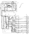
- FIG. 6 is a refrigerant circuit diagram showing the flow of the heat-source-side refrigerant and the heat medium during the heating only operation mode of the air-conditioning apparatus 100 according to Embodiment 1 of the present invention
- FIG. FIG. 3 is a ph diagram of a refrigeration cycle in a heating only operation mode.
- the heating only operation mode will be described by taking as an example a case where a thermal load is generated only in the use side heat exchanger 26a and the use side heat exchanger 26b.
- pipes represented by bold lines indicate pipes through which the heat source side refrigerant and the heat medium flow.
- the direction in which the heat source side refrigerant flows is indicated by a solid line arrow, and the direction in which the heat medium flows is indicated by a broken line arrow. Yes.
- the control device 50 supplies the heat source side refrigerant discharged from the compressor 10 to the heat source side heat exchanger with respect to the first refrigerant flow switching device 11.
- the refrigerant flow path is switched so as to flow into the heat medium relay 3 without passing through the heat medium converter 3.
- the control device 50 performs opening / closing control so that the opening / closing device 17a is closed, the opening / closing device 17b is opened, and the opening / closing device 24 is closed.
- the control apparatus 50 drives the pump 21a and the pump 21b in the heat medium converter 3, opens the heat medium flow control device 25a and the heat medium flow control device 25b, and opens the heat medium flow control device 25c and the heat medium flow rate.
- the adjusting device 25d is fully closed so that the heat medium circulates between the heat exchanger related to heat medium 15a and the heat exchanger related to heat medium 15b, and the use side heat exchanger 26a and the use side heat exchanger 26b. I have to.
- a low-temperature and low-pressure gas refrigerant (point E) is compressed by the compressor 10 and discharged as a high-temperature and high-pressure gas refrigerant (point I), and a check valve in the first refrigerant flow switching device 11 and the first connection pipe 4a. It flows out of the outdoor unit 1 via 13b and the gas-liquid separator 27a.
- the high-temperature and high-pressure gas refrigerant that has flowed out of the outdoor unit 1 flows into the heat medium relay unit 3 through the refrigerant pipe 4.
- the high-temperature and high-pressure gas refrigerant flowing into the heat medium relay unit 3 branches and passes through the second refrigerant flow switching device 18a and the second refrigerant flow switching device 18b to exchange heat between heat media acting as a condenser. Flow into the heat exchanger 15a and the heat exchanger related to heat medium 15b.
- the high-temperature and high-pressure gas refrigerant flowing into the heat exchanger related to heat medium 15a and the heat exchanger related to heat medium 15b is condensed while heating the heat medium by dissipating heat to the heat medium circulating in the heat medium circuit B, It becomes a high-pressure liquid refrigerant (point J).
- the high-pressure liquid refrigerant that has flowed out of the heat exchanger related to heat medium 15a and the heat exchanger related to heat medium 15b is expanded and depressurized by the expansion device 16a and the expansion device 16b, respectively. (Point M), then merges, flows out of the heat medium relay unit 3 through the switching device 17b, flows through the refrigerant pipe 4 and flows into the outdoor unit 1 again.
- the medium-temperature medium-pressure gas-liquid two-phase refrigerant or liquid refrigerant flowing into the outdoor unit 1 flows into the second connection pipe 4b via the gas-liquid separator 27b, and is expanded and depressurized by the expansion device 14a. It becomes a low-pressure gas-liquid two-phase refrigerant (point L).
- This low-temperature and low-pressure gas-liquid two-phase refrigerant flows into the heat source side heat exchanger 12 via the check valve 13c, evaporates while absorbing heat from the outdoor air, and becomes a low-temperature and low-pressure gas refrigerant (point E). .
- the low-temperature and low-pressure gas refrigerant flowing out from the heat source side heat exchanger 12 is again sucked into the compressor 10 via the first refrigerant flow switching device 11 and the accumulator 19.
- the gas-liquid two-phase refrigerant of medium temperature and medium pressure flows into the gas-liquid separator 27b, it is distributed to the liquid refrigerant and the gas-liquid two-phase refrigerant, and the distributed liquid refrigerant (saturated liquid refrigerant, point M ′) is Then, after passing through the backflow prevention device 20, it flows into the injection pipe 4c.
- the liquid refrigerant that has flowed into the injection pipe 4c is expanded and depressurized by the expansion device 14b to become a low-temperature / medium-pressure gas-liquid two-phase refrigerant whose pressure is slightly reduced (point K), and an opening provided in the compression chamber of the compressor 10 Is injected into the compressor 10 from the section.
- the medium-pressure gas refrigerant (point F) and the low-temperature medium-pressure gas-liquid two-phase refrigerant (point K) are mixed, and the temperature of the heat source side refrigerant decreases (point H).
- the discharge temperature of the gas refrigerant discharged from the compressor 10 decreases (point I).
- the discharge temperature of the compressor 10 when the injection operation is not performed is the point G in FIG. 7, and it can be seen that the discharge temperature is lowered from the point G to the point I by the injection operation.
- the control device 50 detects, with respect to the expansion device 16a, a value obtained by converting the pressure detected by the intermediate heat exchanger refrigerant pressure detection means 36a into a saturation temperature and an intermediate heat exchanger refrigerant temperature detection means.
- the opening degree is controlled so that the subcool (degree of supercooling) obtained as a difference from the temperature detected by 35b becomes constant.
- the control device 50 provides the expansion device 16b with a value obtained by converting the pressure detected by the heat exchanger related to heat exchanger refrigerant pressure detecting means 36b into a saturation temperature, and a heat exchanger related to heat exchanger refrigerant temperature detecting means.
- the opening degree is controlled so that the subcool obtained as a difference from the temperature detected by 35d becomes constant.
- the temperature at the intermediate position of the heat exchanger related to heat medium 15 can be measured, the temperature at the intermediate position may be used instead of the heat exchanger related to heat exchanger refrigerant pressure detecting means 36, and in this case, the cost is low. You can configure the system.
- the opening / closing device 24 is closed to prevent the high-pressure refrigerant in the gas-liquid separator 27a from mixing with the medium-pressure refrigerant that has passed through the backflow prevention device 20.
- the expansion device 14a can change the opening area of an electronic expansion valve or the like, and the control device 50 can control the intermediate pressure upstream of the expansion device 14a to an arbitrary pressure. If the opening degree of the expansion device 14a is controlled so that the medium pressure detected by 32 becomes a constant value, the control of the discharge temperature by the expansion device 14b can be stabilized.
- the expansion device 14a is not limited to this, and a plurality of opening areas may be selected by combining on-off valves such as small solenoid valves, or as a capillary tube according to the pressure loss of the refrigerant. An intermediate pressure may be formed, and the controllability is slightly deteriorated, but it is possible to control the discharge temperature as a target.
- control method of the expansion device 14a and the expansion device 14b is not limited as described above, and may be a control method in which the expansion device 14b is fully opened and the discharge temperature of the compressor 10 is controlled by the expansion device 14a. .
- the control is simplified and there is an advantage that an inexpensive device can be used as the expansion device 14b.
- the intermediate pressure detection means 32 may be a pressure sensor, or may calculate the intermediate pressure by calculation using a temperature sensor.
- the subcooling can be controlled by the expansion device 16a and the expansion device 16b. If so, control may be performed so that the intermediate pressure (point M in FIG. 7) on the upstream side of the expansion device 14a is increased. As described above, when the control is performed so that the intermediate pressure is increased, the pressure difference between the compressor 10 and the compression chamber can be increased, so that the injection amount can be increased in the compression chamber and the outside air temperature is low. In this case, an injection amount sufficient to lower the discharge temperature can be supplied to the compression chamber. Further, when the medium pressure is controlled to be high, the medium-pressure liquid refrigerant can flow into the gas-liquid separator 27b, and there is an advantage that the control in the expansion device 14a is easily stabilized.
- the heat of the heat source side refrigerant is transmitted to the heat medium in both the heat exchanger related to heat medium 15a and the heat exchanger related to heat medium 15b, and the heated heat medium is heated by the pump 21a and the pump 21b. It circulates in the medium circulation circuit B.
- the heat medium pressurized and discharged by the pump 21a and the pump 21b flows out of the heat medium converter 3 via the second heat medium flow switching device 23a and the second heat medium flow switching device 23b, and the heat medium It flows into the indoor unit 2a and the indoor unit 2b through the pipe 5, respectively.
- the heat medium flow control device 25c and the heat medium flow control device 25d are in a fully closed state, the heat medium passes through the second heat medium flow switching device 23c and the second heat medium flow switching device 23d. Therefore, the air does not flow into the indoor unit 2c and the indoor unit 2d, respectively.
- the heat medium flowing into the indoor unit 2a and the indoor unit 2b flows into the use side heat exchanger 26a and the use side heat exchanger 26b, respectively.
- the heating operation of the indoor space 7 is implemented when the heat medium which flowed into the utilization side heat exchanger 26a and the utilization side heat exchanger 26b radiates heat to indoor air.
- the heat medium which flowed out from the use side heat exchanger 26a and the use side heat exchanger 26b flows out from the indoor unit 2a and the indoor unit 2b, respectively, flows into the heat medium converter 3 through the heat medium pipe 5. .
- the heat medium flowing into the heat medium converter 3 flows into the heat medium flow control device 25a and the heat medium flow control device 25b.
- the heat medium flow rate adjusting device 25a and the heat medium flow rate adjusting device 25b control the flow rate of the heat medium to a flow rate necessary to cover the air conditioning load required in the room. It flows into the use side heat exchanger 26b.
- the heat medium that has flowed out of the heat medium flow control device 25a flows into the heat exchanger related to heat medium 15a and the heat exchanger related to heat medium 15b, respectively, via the first heat medium flow switching device 22a.
- the heat medium flowing out from the heat medium flow control device 25b flows into the heat exchanger related to heat medium 15a and the heat exchanger related to heat medium 15b via the first heat medium flow switching device 22b.
- the heat medium flowing into the heat exchanger related to heat medium 15a and the heat exchanger related to heat medium 15b is again sucked into the pump 21a and the pump 21b, respectively.
- the first heat medium flow switching device 22a and the first heat medium flow switching device 22b ensure a flow path that flows to both the heat exchanger related to heat medium 15a and the heat exchanger related to heat medium 15b.
- the intermediate opening is set.
- the air conditioning load required in the indoor space 7 includes the temperature detected by the intermediate heat exchanger outlet temperature detecting means 31a or the temperature detected by the intermediate heat exchanger outlet temperature detecting means 31b and the utilization. This can be covered by controlling the difference between the temperature detected by the side heat exchanger outlet temperature detecting means 34 and maintaining the target value.
- the heating operation by the use side heat exchanger 26 should be controlled by the temperature difference between the inlet and the outlet, but the temperature of the heat medium on the inlet side of the use side heat exchanger 26 is the heat exchange between heat media. The temperature is almost the same as the temperature detected by the outlet temperature detecting means 31.
- either the temperature of the heat exchanger related to heat exchanger outlet temperature detecting means 31 a or the temperature of the heat exchanger related to heat exchanger outlet temperature detecting means 31 b may be used, or These average temperatures may be used.
- FIG. 8 is a refrigerant circuit diagram illustrating the flow of the heat-source-side refrigerant and the heat medium in the cooling main operation mode of the air-conditioning apparatus 100 according to Embodiment 1 of the present invention. It is a ph diagram of the refrigeration cycle in the cooling main operation mode.
- the cooling main operation mode will be described by taking as an example a case where a cooling load is generated in the use side heat exchanger 26a and a heating load is generated in the use side heat exchanger 26b.
- the pipes represented by the thick lines indicate the pipes through which the heat source side refrigerant and the heat medium flow.
- the direction in which the heat source side refrigerant flows is indicated by a solid arrow, and the direction in which the heat medium flows is indicated by a broken line arrow. Yes.
- the control device 50 supplies the heat source side refrigerant discharged from the compressor 10 to the heat source side heat exchanger with respect to the first refrigerant flow switching device 11. Switch to 12 Further, the control device 50 performs opening / closing control so that the expansion device 16a is in a fully open state, the opening / closing device 17a and the opening / closing device 17b are in a closed state, and the opening / closing device 24 is in an open state. And the control apparatus 50 drives the pump 21a and the pump 21b in the heat medium converter 3, opens the heat medium flow control device 25a and the heat medium flow control device 25b, and opens the heat medium flow control device 25c and the heat medium flow rate. The adjustment device 25d is fully closed, heat is transferred between the heat exchanger related to heat medium 15a and the use side heat exchanger 26a, and between the heat exchanger related to heat medium 15b and the use side heat exchanger 26b, respectively. The medium is circulated.
- a low-temperature and low-pressure gas refrigerant (point E) is compressed by the compressor 10 and discharged as a high-temperature and high-pressure gas refrigerant (point I), and passes through the first refrigerant flow switching device 11 to be a heat source side heat exchanger. 12 flows into the outdoor air and condenses while dissipating heat, and becomes a high-pressure gas-liquid two-phase refrigerant.
- the high-pressure gas-liquid two-phase refrigerant flowing into the gas-liquid separator 27a is distributed to the liquid refrigerant and the gas-liquid two-phase refrigerant, and the distributed liquid refrigerant (saturated liquid refrigerant, point M ′) is branched. After branching to the pipe 4d and passing through the switchgear 24, it flows into the injection pipe 4c.
- the liquid refrigerant that has flowed into the injection pipe 4c is expanded and depressurized by the expansion device 14b to become a low-temperature and medium-pressure gas-liquid two-phase refrigerant (point K), and from the opening provided in the compression chamber of the compressor 10, the compressor 10 It is injected inside.
- the medium-pressure gas refrigerant (point F) and the low-temperature medium-pressure gas-liquid two-phase refrigerant (point K) are mixed, and the temperature of the heat source side refrigerant decreases (point H).
- the discharge temperature of the gas refrigerant discharged from the compressor 10 decreases (point I).
- the discharge temperature of the compressor 10 when the injection operation is not performed is the point G in FIG. 9, and it can be seen that the discharge temperature is lowered from the point G to the point I by the injection operation.
- the gas-liquid two-phase refrigerant that has flowed into the heat medium relay unit 3 flows into the heat exchanger related to heat medium 15b acting as a condenser via the second refrigerant flow switching device 18b, and enters the heat medium circuit B.
- the heat medium By dissipating heat to the circulating heat medium, the heat medium is condensed while being heated, and becomes a high-pressure liquid refrigerant (point J).
- point J The liquid refrigerant that has flowed out of the heat exchanger related to heat medium 15b is expanded and depressurized by the expansion device 16b, and becomes a low-pressure and low-pressure gas-liquid two-phase refrigerant (point L).
- This gas-liquid two-phase refrigerant flows into the heat exchanger related to heat medium 15a acting as an evaporator via the expansion device 16a, and absorbs heat from the heat medium circulating in the heat medium circuit B, thereby removing the heat medium. It evaporates while cooling and becomes a low-temperature and low-pressure gas refrigerant (point E).
- the gas refrigerant flowing out of the heat exchanger related to heat medium 15a flows out of the heat medium converter 3 through the second refrigerant flow switching device 18a, and flows into the outdoor unit 1 again through the refrigerant pipe 4. .
- the gas refrigerant that has flowed into the outdoor unit 1 is again sucked into the compressor 10 through the first refrigerant flow switching device 11 and the accumulator 19 via the gas-liquid separator 27b and the check valve 13d.
- the control device 50 determines, with respect to the expansion device 16b, the temperature detected by the intermediate heat exchanger refrigerant temperature detecting means 35a and the temperature detected by the intermediate heat exchanger refrigerant temperature detecting means 35b.
- the opening degree is controlled so that the superheat obtained as a difference becomes constant.
- the control device 50 applies a value obtained by converting the pressure detected by the heat exchanger heat exchanger refrigerant pressure detecting means 36b to the saturation temperature and the heat exchanger heat exchanger refrigerant temperature detecting means 35d with respect to the expansion device 16b.
- the opening degree may be controlled so that the subcool obtained as a difference from the detected temperature becomes constant.
- the expansion device 16b may be fully opened, and the superheat or subcool may be controlled by the expansion device 16a.
- the heat of the heat source side refrigerant is transmitted to the heat medium in the heat exchanger related to heat medium 15b, and the heated heat medium is circulated in the heat medium circuit B by the pump 21b. Further, the cold heat of the heat source side refrigerant is transmitted to the heat medium in the heat exchanger related to heat medium 15a, and the cooled heat medium flows through the heat medium circuit B by the pump 21a.
- the heat medium pressurized and flowing out by the pump 21b flows out of the heat medium converter 3 through the second heat medium flow switching device 23b, and flows into the indoor unit 2b through the heat medium pipe 5.
- the heat medium pressurized and discharged by the pump 21a flows out of the heat medium converter 3 through the second heat medium flow switching device 23a, and flows into the indoor unit 2a through the heat medium pipe 5.
- the heat medium flow control device 25c and the heat medium flow control device 25d are in a fully closed state, the heat medium passes through the second heat medium flow switching device 23c and the second heat medium flow switching device 23d. Therefore, the air does not flow into the indoor unit 2c and the indoor unit 2d, respectively.
- the heat medium flowing into the indoor unit 2b flows into the use side heat exchanger 26b, and the heat medium flowing into the indoor unit 2a flows into the use side heat exchanger 26a.
- the heating medium flowing into the use side heat exchanger 26b radiates heat to the indoor air, whereby the heating operation of the indoor space 7 is performed.
- the heat medium flowing into the use side heat exchanger 26a absorbs heat from the indoor air, whereby the cooling operation of the indoor space 7 is performed.
- the heat medium that has flowed out of the use-side heat exchanger 26 b and whose temperature has decreased to some extent flows out of the indoor unit 2 b passes through the heat medium pipe 5, and flows into the heat medium converter 3.
- the heat medium that has flowed out of the use-side heat exchanger 26 a and whose temperature has risen to some extent flows out of the indoor unit 2 a flows through the heat medium pipe 5, and flows into the heat medium converter 3.
- the heat medium flowing into the heat medium converter 3 from the use side heat exchanger 26b flows into the heat medium flow control device 25b, and the heat medium flowing into the heat medium converter 3 from the use side heat exchanger 26a is the heat medium. It flows into the flow rate adjusting device 25a. At this time, the heat medium flow control device 25a and the heat medium flow control device 25b control the flow rate of the heat medium to a flow rate necessary to cover the air conditioning load required in the room, so that the use-side heat exchanger 26a. And it flows into the use side heat exchanger 26b.
- the heat medium flowing out from the heat medium flow control device 25b flows into the heat exchanger related to heat medium 15b via the first heat medium flow switching device 22b and is sucked into the pump 21b again.
- the heat medium flowing out from the heat medium flow control device 25a flows into the heat exchanger related to heat medium 15a via the first heat medium flow switching device 22a and is sucked into the pump 21a again.
- the heated heat medium and the cooled heat medium are not mixed by the action of the first heat medium flow switching device 22 and the second heat medium flow switching device 23, respectively, And it flows in into the utilization side heat exchanger 26 with a cold load.
- the air conditioning load required in the indoor space 7 includes the temperature detected by the heat exchanger related to heat exchanger outlet temperature detecting means 31b on the heating side and the temperature detected by the use side heat exchanger outlet temperature detecting means 34b. On the cooling side, the difference between the temperature detected by the use side heat exchanger outlet temperature detecting means 34a and the temperature detected by the intermediate heat exchanger outlet temperature detecting means 31a is maintained at the target value. Can be covered by
- FIG. 10 is a refrigerant circuit diagram showing the flow of the heat-source-side refrigerant and the heat medium when the air-conditioning apparatus 100 according to Embodiment 1 of the present invention is in the heating-main operation mode, and FIG. It is a ph diagram of the refrigeration cycle in the heating main operation mode.
- the heating main operation mode will be described by taking as an example a case where a heating load is generated in the use side heat exchanger 26a and a cooling load is generated in the use side heat exchanger 26b.
- FIG. 10 is a refrigerant circuit diagram showing the flow of the heat-source-side refrigerant and the heat medium when the air-conditioning apparatus 100 according to Embodiment 1 of the present invention is in the heating-main operation mode
- FIG. It is a ph diagram of the refrigeration cycle in the heating main operation mode.
- the heating main operation mode will be described by taking as an example a case where a heating load is generated in the use side heat exchanger 26a and a cooling load is generated
- pipes represented by thick lines indicate pipes through which the heat source side refrigerant and the heat medium circulate, and the direction in which the heat source side refrigerant flows is indicated by a solid line arrow, and the direction in which the heat medium flows is indicated by a broken line arrow. ing.
- the control device 50 supplies the heat source side refrigerant discharged from the compressor 10 to the heat source side heat exchanger with respect to the first refrigerant flow switching device 11. It switches so that it may be made to flow into heat carrier converter 3 without going through 12. Further, the control device 50 controls opening / closing so that the expansion device 16a is fully opened, the opening / closing device 17a is closed, the opening / closing device 17b is closed, and the opening / closing device 24 is open. And the control apparatus 50 drives the pump 21a and the pump 21b in the heat medium converter 3, opens the heat medium flow control device 25a and the heat medium flow control device 25b, and opens the heat medium flow control device 25c and the heat medium flow rate. The adjustment device 25d is fully closed, heat is transferred between the heat exchanger related to heat medium 15a and the use-side heat exchanger 26b, and between the heat exchanger related to heat medium 15b and the use-side heat exchanger 26a. The medium is circulated.
- a low-temperature and low-pressure gas refrigerant (point E) is compressed by the compressor 10 and discharged as a high-temperature and high-pressure gas refrigerant (point I), and a check valve in the first refrigerant flow switching device 11 and the first connection pipe 4a. It flows out of the outdoor unit 1 via 13b and the gas-liquid separator 27a.
- the high-temperature and high-pressure gas refrigerant that has flowed out of the outdoor unit 1 flows into the heat medium relay unit 3 through the refrigerant pipe 4.
- the high-temperature and high-pressure gas refrigerant that has flowed into the heat medium relay unit 3 flows into the heat exchanger related to heat medium 15b that acts as a condenser via the second refrigerant flow switching device 18b, and passes through the heat medium circuit B.
- the heat medium By dissipating heat to the circulating heat medium, the heat medium is condensed while being heated, and becomes a high-pressure liquid refrigerant (point J).
- the liquid refrigerant flowing out of the heat exchanger related to heat medium 15b is expanded and depressurized by the expansion device 16b, and becomes a medium-pressure gas-liquid two-phase refrigerant (point N).
- This gas-liquid two-phase refrigerant flows into the heat exchanger related to heat medium 15a acting as an evaporator via the expansion device 16a, and absorbs heat from the heat medium circulating in the heat medium circuit B, thereby removing the heat medium. While cooling, the dryness increases (point M).
- the gas-liquid two-phase refrigerant that has flowed out of the heat exchanger related to heat medium 15a flows out of the heat medium converter 3 via the second refrigerant flow switching device 18a, passes through the refrigerant pipe 4, and returns to the outdoor unit 1 again. Inflow.
- the gas-liquid two-phase refrigerant that has flowed into the outdoor unit 1 flows into the second connection pipe 4b via the gas-liquid separator 27b, and is expanded and depressurized by the expansion device 14a.
- Point L This low-temperature and low-pressure gas-liquid two-phase refrigerant flows into the heat source side heat exchanger 12 via the check valve 13c, evaporates while absorbing heat from the outdoor air, and becomes a low-temperature and low-pressure gas refrigerant (point E). .
- the low-temperature and low-pressure gas refrigerant flowing out from the heat source side heat exchanger 12 is again sucked into the compressor 10 via the first refrigerant flow switching device 11 and the accumulator 19.
- the medium-temperature and medium-pressure gas-liquid two-phase refrigerant flowing into the gas-liquid separator 27b is distributed to the liquid refrigerant and the gas-liquid two-phase refrigerant, and the distributed liquid refrigerant (saturated liquid refrigerant, point M ′) is Then, after passing through the backflow prevention device 20, it flows into the injection pipe 4c.
- the liquid refrigerant flowing into the injection pipe 4c is expanded and depressurized by the expansion device 14b to become a low-temperature / medium-pressure gas-liquid two-phase refrigerant whose pressure is slightly reduced (point K), and an opening provided in the compression chamber of the compressor 10 Is injected into the compressor 10 from the section.
- the medium-pressure gas refrigerant (point F) and the low-temperature medium-pressure gas-liquid two-phase refrigerant (point K) are mixed, and the temperature of the heat source side refrigerant decreases (point H).
- the discharge temperature of the gas refrigerant discharged from the compressor 10 decreases (point I).
- the discharge temperature of the compressor 10 when the injection operation is not performed is the point G in FIG. 11, and it can be seen that the discharge temperature is lowered from the point G to the point I by the injection operation.
- the control device 50 detects, with respect to the expansion device 16b, a value obtained by converting the pressure detected by the intermediate heat exchanger refrigerant pressure detection means 36b into a saturation temperature, and an intermediate heat exchanger refrigerant temperature detection means.
- the opening degree is controlled so that the subcool obtained as a difference from the temperature detected by 35d becomes constant.
- the control device 50 may fully open the expansion device 16b and control the subcooling by the expansion device 16a.
- the opening / closing device 24 is closed to prevent the high-pressure refrigerant in the gas-liquid separator 27a from mixing with the medium-pressure refrigerant that has passed through the backflow prevention device 20.
- the expansion device 14a can change the opening area of an electronic expansion valve or the like, and the control device 50 can control the intermediate pressure upstream of the expansion device 14a to an arbitrary pressure. If the opening degree of the expansion device 14a is controlled so that the medium pressure detected by 32 becomes a constant value, the control of the discharge temperature by the expansion device 14b can be stabilized.
- the expansion device 14a is not limited to this, and a plurality of opening areas may be selected by combining on-off valves such as small solenoid valves, or as a capillary tube according to the pressure loss of the refrigerant. An intermediate pressure may be formed, and the controllability is slightly deteriorated, but it is possible to control the discharge temperature as a target.
- control method of the expansion device 14a and the expansion device 14b is not limited as described above, and may be a control method in which the expansion device 14b is fully opened and the discharge temperature of the compressor 10 is controlled by the expansion device 14a. .
- the control is simplified and there is an advantage that an inexpensive device can be used as the expansion device 14b.
- the intermediate pressure cannot be freely controlled, and it is necessary to control the expansion device 14a in consideration of both the intermediate pressure and the discharge temperature.
- the intermediate pressure detection means 32 may be a pressure sensor, or may calculate the intermediate pressure by calculation using a temperature sensor.
- the heating main operation mode it is necessary to cool the heat medium in the heat exchanger related to heat medium 15a, and the pressure (medium pressure) of the refrigerant on the upstream side of the expansion device 14a cannot be controlled so high. If the intermediate pressure cannot be increased, the amount of injection into the compression chamber is reduced, and the amount of decrease in the discharge temperature is reduced. However, since it is necessary to prevent the heat medium from freezing, when the outside air temperature is low (for example, the outside air temperature is ⁇ 5 ° C. or lower), the heating main operation mode should not be performed, and the outside air temperature is high. There is no problem because the discharge temperature is not so high and the injection amount is not so large.
- the heat of the heat source side refrigerant is transmitted to the heat medium in the heat exchanger related to heat medium 15b, and the heated heat medium is circulated in the heat medium circuit B by the pump 21b. Further, the cold heat of the heat source side refrigerant is transmitted to the heat medium in the heat exchanger related to heat medium 15a, and the cooled heat medium flows through the heat medium circuit B by the pump 21a.
- the heat medium pressurized and discharged by the pump 21b flows out from the heat medium converter 3 through the second heat medium flow switching device 23a, and flows into the indoor unit 2a through the heat medium pipe 5.
- the heat medium pressurized and discharged by the pump 21a flows out of the heat medium converter 3 through the second heat medium flow switching device 23b, and flows into the indoor unit 2b through the heat medium pipe 5.
- the heat medium flow control device 25c and the heat medium flow control device 25d are in a fully closed state, the heat medium passes through the second heat medium flow switching device 23c and the second heat medium flow switching device 23d. Therefore, the air does not flow into the indoor unit 2c and the indoor unit 2d, respectively.
- the heat medium flowing into the indoor unit 2b flows into the use side heat exchanger 26b, and the heat medium flowing into the indoor unit 2a flows into the use side heat exchanger 26a.
- the heat medium flowing into the use side heat exchanger 26b absorbs heat from the indoor air, whereby the cooling operation of the indoor space 7 is performed.
- the heating medium flowing into the use side heat exchanger 26a radiates heat to the indoor air, whereby the heating operation of the indoor space 7 is performed.
- the heat medium that has flowed out of the use side heat exchanger 26b and whose temperature has risen to some extent flows out of the indoor unit 2b passes through the heat medium pipe 5, and flows into the heat medium converter 3.
- the heat medium that has flowed out of the use-side heat exchanger 26a and whose temperature has been lowered to some extent flows out of the indoor unit 2a flows through the heat medium pipe 5, and flows into the heat medium converter 3.
- the heat medium flowing into the heat medium converter 3 from the use side heat exchanger 26b flows into the heat medium flow control device 25b, and the heat medium flowing into the heat medium converter 3 from the use side heat exchanger 26a is the heat medium. It flows into the flow rate adjusting device 25a. At this time, the heat medium flow rate adjusting device 25a and the heat medium flow rate adjusting device 25b control the flow rate of the heat medium to a flow rate necessary to cover the air conditioning load required in the room. It flows into the use side heat exchanger 26b.
- the heat medium flowing out of the heat medium flow control device 25b flows into the heat exchanger related to heat medium 15a via the first heat medium flow switching device 22b, and is sucked into the pump 21a again.
- the heat medium flowing out from the heat medium flow control device 25a flows into the heat exchanger related to heat medium 15b via the first heat medium flow switching device 22a and is sucked into the pump 21b again.
- the heated heat medium and the cooled heat medium are not mixed by the action of the first heat medium flow switching device 22 and the second heat medium flow switching device 23, respectively, And it flows in into the utilization side heat exchanger 26 with a cold load.
- the air conditioning load required in the indoor space 7 includes the temperature detected by the heat exchanger related to heat exchanger outlet temperature detecting means 31b on the heating side and the temperature detected by the use side heat exchanger outlet temperature detecting means 34a. On the cooling side, the difference between the temperature detected by the use side heat exchanger outlet temperature detecting means 34b and the temperature detected by the intermediate heat exchanger outlet temperature detecting means 31a is maintained at the target value. Can be covered by
- the heat exchanger related to heat medium 15b is always on the heating side and the heat exchanger related to heat medium in both the cooling main operation mode and the heating main operation mode.
- 15a is configured to be on the cooling side.
- the use side heat for performing the heating is used.
- the first heat medium flow switching device 22 and the second heat medium flow switching device 23 corresponding to the exchanger 26 are switched to a flow channel connected to the heat exchanger related to heat medium 15b for heating the heat medium, and cooling is performed.
- the first heat medium flow switching device 22 and the second heat medium flow switching device 23 corresponding to the use-side heat exchanger 26 that performs the above are connected to the heat exchanger related to heat medium 15a for cooling the heat medium.
- the expansion device 14b when an electronic expansion valve is used as the expansion device 14b, when the gas-liquid two-phase refrigerant flows in and the gas refrigerant and the liquid refrigerant flow separately, the gas is supplied to the expansion unit of the expansion device 14b. May occur separately from each other, and the pressure on the outlet side of the expansion device 14b may not be stable. In particular, when the dryness is small, the refrigerant is separated and the tendency is strong. Therefore, when a device having a structure as shown in FIG. 12 is used as the expansion device 14b, stable control is possible even if a gas-liquid two-phase refrigerant flows. When a gas-liquid separator is used, the throttling device 14b can be controlled sufficiently stably without such work. However, if the throttling device 14b is structured as shown in FIG. Regardless, more stable control is possible.
- the structure of the throttle device shown in FIG. 12 below is not limited to being applied to the throttle device 14b, and is a throttle through which gas-liquid two-phase refrigerant flows in the heating only operation mode and the heating main operation mode. Even if it is applied to the device 14a, the same effect is obtained.
- FIG. 12 is a structural diagram of the expansion device 14b (or the expansion device 14a) of the air-conditioning apparatus 100 according to Embodiment 1 of the present invention.
- the throttling device 14b includes an inflow pipe 41, an outflow pipe 42, a throttling portion 43, a valve body 44, a motor 45, and a stirrer 46.
- the stirrer 46 is the inflow pipe. 41 is installed.
- the gas-liquid two-phase refrigerant that has flowed in from the inflow pipe 41 is mixed almost uniformly as the gas refrigerant and the liquid refrigerant are stirred by the stirring device 46.
- the gas-liquid two-phase refrigerant in which the gas refrigerant and the liquid refrigerant are almost uniformly mixed is squeezed by the valve body 44 in the throttle portion 43, decompressed, and flows out from the outflow pipe 42. At this time, the position of the valve body 44 is controlled by the motor 45, and the throttle amount at the throttle unit 43 is controlled.
- the motor 45 may be driven and controlled by the control device 50.
- the stirrer 46 may be any device as long as it can create a state in which the gas refrigerant and the liquid refrigerant are almost uniformly mixed, but can be realized by using, for example, a foam metal.
- This foam metal is a metal porous body having a three-dimensional network structure like a resin foam such as sponge, and has the highest porosity (porosity) among the metal porous bodies (80% to 97%).
- the state where the discharge temperature is high is a cooling only operation mode when the outside air temperature is high.
- the frequency of the compressor 10 is increased and the condensation temperature is increased. This occurs when the frequency of the compressor 10 is increased and the evaporation temperature is lowered in order to keep the condensation temperature at a target temperature, for example, 49 degrees, in the heating only operation mode when the outside air temperature is low.
- the cooling main operation mode it is necessary to maintain both the condensation temperature and the evaporation temperature at the target temperatures (for example, 49 ° C. and 0 ° C.).
- the condensation temperature Since both the evaporation temperature and the evaporation temperature are higher than the target temperature, a state in which the frequency of the compressor 10 is very high is unlikely to occur as in the cooling only operation mode when the outside air temperature is high, and the condensation temperature does not become too high. As described above, the frequency increase of the compressor 10 is limited. For this reason, in the cooling main operation mode, the discharge temperature is unlikely to increase. For this reason, as shown in FIG. 13, the gas-liquid separator 27a is eliminated, and the refrigerant is simply branched. In the cooling main operation mode, the opening / closing device 24 is closed and the injection operation is not performed. Good.
- the discharge temperature can be lowered by injecting a low-temperature heat source side refrigerant from the outside during the compression process.
- the corresponding first heat medium flow switching device 22 and second The heat medium flow switching device 23 is set to an intermediate opening so that the heat medium flows through both the heat exchanger related to heat medium 15a and the heat exchanger related to heat medium 15b.
- both the heat exchanger related to heat medium 15a and the heat exchanger related to heat medium 15b can be used for heating operation or cooling operation, so that the heat transfer area is increased and efficient heating operation or cooling operation is performed. Can be done.
- the first heat medium flow switching device corresponding to the use side heat exchanger 26 performing the heating operation. 22 and the second heat medium flow switching device 23 are switched to a flow path connected to the heat exchanger related to heat medium 15b for heating, and the first heat medium corresponding to the use side heat exchanger 26 performing the cooling operation.
- the first heat medium flow switching device 22 and the second heat medium flow switching device 23 can switch a three-way flow path such as a three-way valve.
- the present invention is not limited to this, and an open / close valve or the like As long as the two channels can be switched, the channel can be switched.
- it is possible to change the flow rate of the three-way flow path such as a stepping motor-driven mixing valve, or a combination of two things that can change the flow rate of the two-way flow path such as an electronic expansion valve. Good. In this case, it is possible to prevent water hammer due to sudden opening and closing of the flow path.
- the heat medium flow control device 25 is a two-way valve has been described as an example, but a bypass that bypasses the use-side heat exchanger 26 with a control valve having a three-way flow path. You may make it install with a pipe
- the heat medium flow control device 25 may be a stepping motor drive type that can control the flow rate flowing through the flow path, and may be a two-way valve or a device in which one end of the three-way valve is closed. Alternatively, an average flow rate may be controlled by repeatedly turning ON / OFF using a valve that opens and closes a two-way flow path such as an open / close valve.
- the heat medium flow control device 25 is not limited thereto, and may be built in the indoor unit 2. It is good also as a structure installed in the different body (namely, heat-medium piping 5) from the converter 3 and the indoor unit 2.
- the second refrigerant flow switching device 18 is a four-way valve. However, the second refrigerant flow switching device 18 is not limited to this, and a plurality of two-way flow switching valves or three-way flow switching valves are used in the same manner. You may comprise so that a refrigerant
- coolant may flow.
- a heat blower is attached to the heat source side heat exchanger 12 and the use side heat exchangers 26a to 26d, and in many cases, condensation or evaporation is promoted by air blowing, but the present invention is not limited to this.
- the use side heat exchangers 26a to 26d may be panel heaters using radiation
- the heat source side heat exchanger 12 is a water-cooled type in which heat is transferred by water or antifreeze. These types may also be used, and any type having a structure capable of radiating or absorbing heat can be used.
- the number of pumps 21a and 21b is not limited to one, and a plurality of small capacity pumps may be arranged in parallel.
- a normal gas-liquid separator has an action of separating the gas refrigerant and the liquid refrigerant in the gas-liquid two-phase refrigerant.
- the gas-liquid separator 27 according to the present embodiment, when the gas-liquid two-phase refrigerant flows into the inlet of the gas-liquid separator 27 as described above, A part of the liquid refrigerant is separated from the phase refrigerant and flows into the branch pipe 4d, and the remaining gas-liquid two-phase refrigerant (which has become slightly dry) is allowed to flow out of the gas-liquid separator 27. Therefore, as shown in FIG.
- the gas-liquid separator 27 has a structure that is long in the lateral direction, and an inlet pipe and an outlet pipe are attached to the side of the gas-liquid separator 27, and a liquid refrigerant take-out pipe.
- a horizontal gas-liquid separator having a structure in which liquid refrigerant can be separated and flowed below the gas-liquid separator 27.
- the gas-liquid separator may have any structure as long as it can separate a part of the liquid refrigerant from the refrigerant that flows in the gas-liquid two-phase and allows the remaining gas-liquid two-phase refrigerant to flow out. .
- the heating only operation mode and the heating main operation mode when the air temperature around the heat source side heat exchanger 12 is low, a low temperature and low pressure heat source side refrigerant below freezing is inside the refrigerant pipe of the heat source side heat exchanger 12. Since it flows, frost forms around the heat source side heat exchanger 12.
- frost formation occurs in the heat source side heat exchanger 12
- the frost layer becomes a thermal resistance, and the flow path through which the air around the heat source side heat exchanger 12 flows becomes narrow and the air hardly flows. Heat exchange between the air and the air is hindered, and the heating capacity and operating efficiency of the equipment are reduced.
- the frost formation of the heat source side heat exchanger 12 increases, the defrost operation which melts the frost around the heat source side heat exchanger 12 is implemented.
- the heat source side refrigerant is compressed by the compressor 10, heated, discharged from the compressor 10, and flows into the heat source side heat exchanger 12 through the first refrigerant flow switching device 11. And the heat source side refrigerant
- the heat-source-side refrigerant that has flowed out of the heat-source-side heat exchanger 12 passes through the check valve 13a, reaches the gas-liquid separator 27a, and is divided by the gas-liquid separator 27a.
- One flow branched by the gas-liquid separator 27 a flows out of the outdoor unit 1 and flows into the heat medium relay unit 3 through the refrigerant pipe 4.
- the heat-source-side refrigerant that has flowed into the heat medium relay unit 3 flows out of the heat medium relay unit 3 through the open / close device 17a and the open / close device 17b, and passes through the refrigerant pipe 4 to the outdoor unit 1 again. Inflow.
- the heat-source-side refrigerant that has flowed into the outdoor unit 1 is again sucked into the compressor 10 via the gas-liquid separator 27b, the check valve 13d, the first refrigerant flow switching device 11 and the accumulator 19. Is done.
- the expansion device 16a and the expansion device 16b are fully closed or have a small opening at which the heat source side refrigerant does not flow, and the heat exchanger related to heat medium 15a and the heat exchanger related to heat medium 15b include a heat source.
- the side refrigerant is prevented from flowing.
- the other flow divided by the gas-liquid separator 27a flows into the branch pipe 4d, flows into the injection pipe 4c through the open / close device 24, and is compressed through the throttle device 14b in the fully open state.
- the refrigerant is injected into the compression chamber of the machine 10 and merges with the heat source side refrigerant (one flow divided by the gas-liquid separator 27a) drawn into the compressor 10 through the accumulator 19.
- the pump 21b is driven to circulate the heat medium to the use side heat exchanger 26 (the use side heat exchangers 26a and 26b in FIG. 14) that requires heating. Thereby, even during the defrosting operation, the heating operation can be continued by the warm heat stored in the heat medium.
- the pump 21a may be driven, or during the defrosting operation, the pump 21a and the pump 21b may be stopped to stop the heating operation. Good.
- the heat source side refrigerant is branched in the gas-liquid separator 27a, and a part of the refrigerant is Inject into the compression chamber.
- the flow rate of the heat source side refrigerant to be circulated to the heat medium relay unit 3 away from the outdoor unit 1 can be reduced by the injection flow rate, the power of the compressor 10 can be reduced.
- Embodiment 2 FIG. The air conditioning apparatus 100 according to the present embodiment will be described focusing on differences from the configuration and operation of the air conditioning apparatus 100 according to Embodiment 1.
- FIG. 15 is a schematic diagram illustrating an example of a circuit configuration of the air-conditioning apparatus 100 according to Embodiment 2 of the present invention.
- the structure of the air conditioning apparatus 100 will be described with reference to FIG.
- the inter-refrigerant heat exchanger 28 is installed in the injection piping 4 c connected to the opening of the compression chamber of the compressor 10. From the connection part of the injection pipe 4c connected to the branch pipe 4d, the refrigerant pipe in order of the inter-refrigerant heat exchanger 28, the expansion device 14b, the inter-refrigerant heat exchanger 28, and the opening of the compression chamber of the compressor 10 It is connected. That is, among the injected heat source side refrigerant, the heat source side refrigerant before flowing into the expansion device 14b and the heat source side refrigerant after passing through the expansion device 14b exchange heat in the inter-refrigerant heat exchanger 28. It has a configuration.
- each operation mode of the air-conditioning apparatus 100 according to the present embodiment will be described.
- the control apparatus 50 installed in the outdoor unit 1 shall implement control of the air conditioning apparatus 100 whole.
- the flow of the heat medium of the air conditioning apparatus 100 according to the present embodiment is the same as each operation mode of the air conditioning apparatus 100 according to the first embodiment.
- FIG. 16 is a refrigerant circuit diagram illustrating the flow of the heat-source-side refrigerant and the heat medium when the air-conditioning apparatus 100 according to Embodiment 2 of the present invention is in the cooling only operation mode
- FIG. FIG. 3 is a ph diagram of a refrigeration cycle in a cooling only operation mode.
- the cooling only operation mode will be described by taking as an example a case where a cooling load is generated only in the use side heat exchanger 26a and the use side heat exchanger 26b.
- the pipes indicated by bold lines indicate the pipes through which the heat source side refrigerant and the heat medium flow.
- the direction in which the heat source side refrigerant flows is indicated by a solid line arrow, and the direction in which the heat medium flows is indicated by a broken line arrow. Yes.
- a low-temperature and low-pressure gas refrigerant (point E) is compressed by the compressor 10 and discharged as a high-temperature and high-pressure gas refrigerant (point I), and passes through the first refrigerant flow switching device 11 to be a heat source side heat exchanger. 12 is condensed while radiating heat to the outdoor air, and becomes a high-pressure liquid refrigerant.
- the liquid refrigerant that has flowed into the inter-refrigerant heat exchanger 28 is cooled by the heat source side refrigerant whose pressure and temperature have been reduced by the expansion device 14b (point J ').
- the liquid refrigerant flowing out from the inter-refrigerant heat exchanger 28 is expanded and depressurized by the expansion device 14b, becomes a low-temperature / medium-pressure heat source side refrigerant (point K '), and flows into the inter-refrigerant heat exchanger 28 again.
- the heat-source-side refrigerant that has flowed again into the inter-refrigerant heat exchanger 28 is heated by the liquid refrigerant before being decompressed by the expansion device 14b, and becomes a low-temperature medium-pressure gas-liquid two-phase refrigerant (point K) whose temperature has risen to some extent. .
- the gas-liquid two-phase refrigerant that has flowed out of the inter-refrigerant heat exchanger 28 is injected into the compressor 10 through an opening provided in the compression chamber of the compressor 10.
- the medium-pressure gas refrigerant (point F) and the low-temperature medium-pressure gas-liquid two-phase refrigerant (point K) are mixed, and the temperature of the heat source side refrigerant decreases (point H).
- the discharge temperature of the gas refrigerant discharged from the compressor 10 decreases (point I).
- the discharge temperature of the compressor 10 when the injection operation is not performed is the point G in FIG. 17, and it can be seen that the discharge temperature is lowered from the point G to the point I by the injection operation.
- the high-pressure liquid refrigerant that has flowed into the heat medium relay unit 3 passes through the opening / closing device 17a, and then branches, flows into the expansion device 16a and the expansion device 16b, is expanded and depressurized, and is a low-temperature and low-pressure gas-liquid two-phase refrigerant.
- Point L This gas-liquid two-phase refrigerant flows into each of the heat exchanger related to heat medium 15a and the heat exchanger related to heat medium 15b acting as an evaporator and absorbs heat from the heat medium circulating in the heat medium circuit B to generate heat.
- the medium evaporates while cooling, and becomes a low-temperature and low-pressure gas refrigerant (point E).
- the gas refrigerant that has flowed out of the heat exchanger related to heat medium 15a and the heat exchanger related to heat medium 15b merges via the second refrigerant flow switching device 18a and the second refrigerant flow switching device 18b, respectively. It flows out of the unit 3, passes through the refrigerant pipe 4, and flows into the outdoor unit 1 again.
- the gas refrigerant that has flowed into the outdoor unit 1 is again sucked into the compressor 10 via the first refrigerant flow switching device 11 and the accumulator 19 through the gas-liquid separator 27b and the check valve 13d.
- the expansion device 14b may not be able to perform stable control, and the subcooling at the outlet of the heat source side heat exchanger 12 may be caused due to a small amount of the heat source side refrigerant enclosed. Is small, the liquid refrigerant can be reliably supplied to the expansion device 14b by cooling by the action of the inter-refrigerant heat exchanger 28, and stable control is possible.
- FIG. 18 is a refrigerant circuit diagram showing the flow of the heat-source-side refrigerant and the heat medium in the heating only operation mode of the air-conditioning apparatus 100 according to Embodiment 2 of the present invention.
- FIG. 3 is a ph diagram of a refrigeration cycle in a heating only operation mode.
- the heating only operation mode will be described by taking as an example a case where a thermal load is generated only in the use side heat exchanger 26a and the use side heat exchanger 26b.
- the pipes indicated by bold lines indicate the pipes through which the heat source side refrigerant and the heat medium flow.
- the direction in which the heat source side refrigerant flows is indicated by the solid line arrow, and the direction in which the heat medium flows is indicated by the broken line arrow. Yes.
- a low-temperature and low-pressure gas refrigerant (point E) is compressed by the compressor 10 and discharged as a high-temperature and high-pressure gas refrigerant (point I), and a check valve in the first refrigerant flow switching device 11 and the first connection pipe 4a. It flows out of the outdoor unit 1 via 13b and the gas-liquid separator 27a.
- the high-temperature and high-pressure gas refrigerant that has flowed out of the outdoor unit 1 flows into the heat medium relay unit 3 through the refrigerant pipe 4.
- the high-temperature and high-pressure gas refrigerant flowing into the heat medium relay unit 3 branches and passes through the second refrigerant flow switching device 18a and the second refrigerant flow switching device 18b to exchange heat between heat media acting as a condenser. Flow into the heat exchanger 15a and the heat exchanger related to heat medium 15b.
- the high-temperature and high-pressure gas refrigerant flowing into the heat exchanger related to heat medium 15a and the heat exchanger related to heat medium 15b is condensed while heating the heat medium by dissipating heat to the heat medium circulating in the heat medium circuit B, It becomes a high-pressure liquid refrigerant (point J).
- the high-pressure liquid refrigerant that has flowed out of the heat exchanger related to heat medium 15a and the heat exchanger related to heat medium 15b is expanded and depressurized by the expansion device 16a and the expansion device 16b, respectively. (Point M), then merges, flows out of the heat medium relay unit 3 through the switching device 17b, flows through the refrigerant pipe 4 and flows into the outdoor unit 1 again.
- the medium-temperature medium-pressure gas-liquid two-phase refrigerant or liquid refrigerant flowing into the outdoor unit 1 flows into the second connection pipe 4b via the gas-liquid separator 27b, and is expanded and depressurized by the expansion device 14a. It becomes a low-pressure gas-liquid two-phase refrigerant (point L).
- This low-temperature and low-pressure gas-liquid two-phase refrigerant flows into the heat source side heat exchanger 12 via the check valve 13c, evaporates while absorbing heat from the outdoor air, and becomes a low-temperature and low-pressure gas refrigerant (point E). .
- the low-temperature and low-pressure gas refrigerant flowing out from the heat source side heat exchanger 12 is again sucked into the compressor 10 via the first refrigerant flow switching device 11 and the accumulator 19.
- the medium-temperature and medium-pressure gas-liquid two-phase refrigerant flowing into the gas-liquid separator 27b is distributed to the liquid refrigerant and the gas-liquid two-phase refrigerant, and the distributed liquid refrigerant (saturated liquid refrigerant, point M ′) is Then, after passing through the backflow prevention device 20, it flows into the injection pipe 4c.
- the liquid refrigerant that has flowed into the injection pipe 4 c flows into the inter-refrigerant heat exchanger 28.
- the liquid refrigerant that has flowed into the inter-refrigerant heat exchanger 28 is cooled by the heat source side refrigerant whose pressure and temperature are reduced by the expansion device 14b (point M ′′).
- the liquid refrigerant flowing out from the inter-refrigerant heat exchanger 28 is expanded and depressurized by the expansion device 14b, becomes a low-temperature / medium-pressure heat source side refrigerant (point K '), and flows into the inter-refrigerant heat exchanger 28 again.
- the heat-source-side refrigerant that has flowed again into the inter-refrigerant heat exchanger 28 is heated by the liquid refrigerant before being decompressed by the expansion device 14b, and the dryness increases (point K).
- the gas-liquid two-phase refrigerant that has flowed out of the inter-refrigerant heat exchanger 28 is injected into the compressor 10 through an opening provided in the compression chamber of the compressor 10.
- the medium-pressure gas refrigerant (point F) and the low-temperature medium-pressure gas-liquid two-phase refrigerant (point K) are mixed, and the temperature of the heat source side refrigerant decreases (point H).
- the discharge temperature of the gas refrigerant discharged from the compressor 10 decreases (point I).
- the discharge temperature of the compressor 10 when the injection operation is not performed is the point G in FIG. 19, and it can be seen that the discharge temperature is lowered from the point G to the point I by the injection operation.
- the refrigerant in the saturated liquid state is actually a state containing a small amount of minute gas refrigerant, and becomes a gas-liquid two-phase state with a slight pressure loss.
- the expansion device 14b may not be able to perform stable control.
- the expansion device 14b is reliably cooled by the action of the inter-refrigerant heat exchanger 28. Liquid refrigerant can be supplied to the tank, and stable control is possible.
- FIG. 20 is a refrigerant circuit diagram illustrating the flow of the heat-source-side refrigerant and the heat medium during the cooling main operation mode of the air-conditioning apparatus 100 according to Embodiment 2 of the present invention. It is a ph diagram of the refrigeration cycle in the cooling main operation mode.
- the cooling main operation mode will be described by taking as an example a case where a cooling load is generated in the use side heat exchanger 26a and a heating load is generated in the use side heat exchanger 26b.
- the pipes represented by bold lines indicate the pipes through which the heat source side refrigerant and the heat medium flow.
- the direction in which the heat source side refrigerant flows is indicated by the solid line arrow, and the direction in which the heat medium flows is indicated by the broken line arrow. Yes.
- a low-temperature and low-pressure gas refrigerant (point E) is compressed by the compressor 10 and discharged as a high-temperature and high-pressure gas refrigerant (point I), and passes through the first refrigerant flow switching device 11 to be a heat source side heat exchanger. 12 flows into the outdoor air and condenses while dissipating heat, and becomes a high-pressure gas-liquid two-phase refrigerant.
- the high-pressure gas-liquid two-phase refrigerant flowing into the gas-liquid separator 27a is distributed to the liquid refrigerant and the gas-liquid two-phase refrigerant, and the distributed liquid refrigerant (saturated liquid refrigerant, point M ′) is branched. After branching to the pipe 4d and passing through the switchgear 24, it flows into the injection pipe 4c.
- the liquid refrigerant that has flowed into the injection pipe 4 c flows into the inter-refrigerant heat exchanger 28.
- the liquid refrigerant that has flowed into the inter-refrigerant heat exchanger 28 is cooled by the heat source side refrigerant whose pressure and temperature are reduced by the expansion device 14b (point M ′′).
- the liquid refrigerant flowing out from the inter-refrigerant heat exchanger 28 is expanded and depressurized by the expansion device 14b, becomes a low-temperature / medium-pressure heat source side refrigerant (point K '), and flows into the inter-refrigerant heat exchanger 28 again.
- the heat-source-side refrigerant that has flowed again into the inter-refrigerant heat exchanger 28 is heated by the liquid refrigerant before being decompressed by the expansion device 14b, and the dryness increases (point K).
- the gas-liquid two-phase refrigerant that has flowed out of the inter-refrigerant heat exchanger 28 is injected into the compressor 10 through an opening provided in the compression chamber of the compressor 10.
- the medium-pressure gas refrigerant (point F) and the low-temperature medium-pressure gas-liquid two-phase refrigerant (point K) are mixed, and the temperature of the heat source side refrigerant decreases (point H).
- the discharge temperature of the gas refrigerant discharged from the compressor 10 decreases (point I).
- the discharge temperature of the compressor 10 when the injection operation is not performed is the point G in FIG. 21, and it can be seen that the discharge temperature is lowered from the point G to the point I by the injection operation.
- the gas-liquid two-phase refrigerant that has flowed into the heat medium relay unit 3 flows into the heat exchanger related to heat medium 15b acting as a condenser via the second refrigerant flow switching device 18b, and enters the heat medium circuit B.
- the heat medium By dissipating heat to the circulating heat medium, the heat medium is condensed while being heated, and becomes a high-pressure liquid refrigerant (point J).
- point J The liquid refrigerant that has flowed out of the heat exchanger related to heat medium 15b is expanded and depressurized by the expansion device 16b, and becomes a low-pressure and low-pressure gas-liquid two-phase refrigerant (point L).
- This gas-liquid two-phase refrigerant flows into the heat exchanger related to heat medium 15a acting as an evaporator via the expansion device 16a, and absorbs heat from the heat medium circulating in the heat medium circuit B, thereby removing the heat medium. It evaporates while cooling and becomes a low-temperature and low-pressure gas refrigerant (point E).
- the gas refrigerant flowing out of the heat exchanger related to heat medium 15a flows out of the heat medium converter 3 through the second refrigerant flow switching device 18a, and flows into the outdoor unit 1 again through the refrigerant pipe 4. .
- the gas refrigerant that has flowed into the outdoor unit 1 is again sucked into the compressor 10 through the first refrigerant flow switching device 11 and the accumulator 19 via the gas-liquid separator 27b and the check valve 13d.
- the refrigerant in the saturated liquid state is actually a state containing a small amount of minute gas refrigerant, and becomes a gas-liquid two-phase state with a slight pressure loss.
- the expansion device 14b may not be able to perform stable control.
- the expansion device 14b is reliably cooled by the action of the inter-refrigerant heat exchanger 28. Liquid refrigerant can be supplied to the tank, and stable control is possible.
- FIG. 22 is a refrigerant circuit diagram illustrating the flow of the heat-source-side refrigerant and the heat medium when the air-conditioning apparatus 100 according to Embodiment 2 of the present invention is in the heating-main operation mode, and FIG. It is a ph diagram of the refrigeration cycle in the heating main operation mode.
- the heating main operation mode will be described by taking as an example a case where a thermal load is generated in the use side heat exchanger 26 a and a cold load is generated in the use side heat exchanger 26 b.
- FIG. 22 is a refrigerant circuit diagram illustrating the flow of the heat-source-side refrigerant and the heat medium when the air-conditioning apparatus 100 according to Embodiment 2 of the present invention is in the heating-main operation mode
- FIG. It is a ph diagram of the refrigeration cycle in the heating main operation mode.
- the heating main operation mode will be described by taking as an example a case where a thermal load is generated in the use side heat exchanger 26 a and
- the pipes indicated by bold lines indicate the pipes through which the heat source side refrigerant and the heat medium circulate, and the direction in which the heat source side refrigerant flows is indicated by a solid line arrow, and the direction in which the heat medium flows is indicated by a broken line arrow. ing.
- a low-temperature and low-pressure gas refrigerant (point E) is compressed by the compressor 10 and discharged as a high-temperature and high-pressure gas refrigerant (point I), and a check valve in the first refrigerant flow switching device 11 and the first connection pipe 4a. It flows out of the outdoor unit 1 via 13b and the gas-liquid separator 27a.
- the high-temperature and high-pressure gas refrigerant that has flowed out of the outdoor unit 1 flows into the heat medium relay unit 3 through the refrigerant pipe 4.
- the high-temperature and high-pressure gas refrigerant that has flowed into the heat medium relay unit 3 flows into the heat exchanger related to heat medium 15b that acts as a condenser via the second refrigerant flow switching device 18b, and passes through the heat medium circuit B.
- the heat medium By dissipating heat to the circulating heat medium, the heat medium is condensed while being heated, and becomes a high-pressure liquid refrigerant (point J).
- the liquid refrigerant flowing out of the heat exchanger related to heat medium 15b is expanded and depressurized by the expansion device 16b, and becomes a medium-pressure gas-liquid two-phase refrigerant (point N).
- This gas-liquid two-phase refrigerant flows into the heat exchanger related to heat medium 15a acting as an evaporator via the expansion device 16a, and absorbs heat from the heat medium circulating in the heat medium circuit B, thereby removing the heat medium. While cooling, the dryness increases (point M).
- the gas-liquid two-phase refrigerant that has flowed out of the heat exchanger related to heat medium 15a flows out of the heat medium converter 3 via the second refrigerant flow switching device 18a, passes through the refrigerant pipe 4, and returns to the outdoor unit 1 again. Inflow.
- the gas-liquid two-phase refrigerant that has flowed into the outdoor unit 1 flows into the second connection pipe 4b via the gas-liquid separator 27b, and is expanded and depressurized by the expansion device 14a.
- Point L This low-temperature and low-pressure gas-liquid two-phase refrigerant flows into the heat source side heat exchanger 12 via the check valve 13c, evaporates while absorbing heat from the outdoor air, and becomes a low-temperature and low-pressure gas refrigerant (point E). .
- the low-temperature and low-pressure gas refrigerant flowing out from the heat source side heat exchanger 12 is again sucked into the compressor 10 via the first refrigerant flow switching device 11 and the accumulator 19.
- the medium-temperature and medium-pressure gas-liquid two-phase refrigerant flowing into the gas-liquid separator 27b is distributed to the liquid refrigerant and the gas-liquid two-phase refrigerant, and the distributed liquid refrigerant (saturated liquid refrigerant, point M ′) is Then, after passing through the backflow prevention device 20, it flows into the injection pipe 4c.
- the liquid refrigerant that has flowed into the injection pipe 4c flows into the inter-refrigerant heat exchanger 28, and is cooled by the heat source refrigerant whose pressure and temperature are reduced by the expansion device 14b (point M ′′).
- the liquid refrigerant that has flowed out of the inter-refrigerant heat exchanger 28 is expanded and depressurized by the expansion device 14b to become a low-temperature / medium-pressure heat source side refrigerant (point K ′), and flows into the inter-refrigerant heat exchanger 28 again. Heated by the liquid refrigerant before being depressurized by 14b, the dryness increases (point K).
- the gas-liquid two-phase refrigerant that has flowed out of the inter-refrigerant heat exchanger 28 is injected into the compressor 10 through an opening provided in the compression chamber of the compressor 10.
- the medium-pressure gas refrigerant (point F) and the low-temperature medium-pressure gas-liquid two-phase refrigerant (point K) are mixed, and the temperature of the heat source side refrigerant decreases (point H).
- the discharge temperature of the gas refrigerant discharged from the compressor 10 decreases (point I).
- the discharge temperature of the compressor 10 when the injection operation is not performed is the point G in FIG. 23, and it can be seen that the discharge temperature is lowered from the point G to the point I by the injection operation.
- the refrigerant in the saturated liquid state is actually a state containing a small amount of minute gas refrigerant, and becomes a gas-liquid two-phase state with a slight pressure loss.
- the expansion device 14b may not be able to perform stable control.
- the expansion device 14b is reliably cooled by the action of the inter-refrigerant heat exchanger 28. Liquid refrigerant can be supplied to the tank, and stable control is possible.
- Embodiment 3 FIG.
- the air conditioner 100a according to the present embodiment will be described focusing on differences from the configuration and operation of the air conditioner 100 according to the first embodiment.
- FIG. 24 is a schematic diagram illustrating an example of a circuit configuration of an air-conditioning apparatus 100a according to Embodiment 3 of the present invention.
- the structure of the air conditioning apparatus 100a will be described with reference to FIG.
- the outdoor unit 1a and the heat medium relay unit 3a are connected by refrigerant pipes 4e to 4g through which the heat source side refrigerant flows.
- the branch portion 27d, the first refrigerant flow switching device 48, the heat source side heat exchanger 12, the expansion device 14a, and the branch portion 27c are connected in this order from the discharge side of the compressor 10 by the refrigerant pipe. Yes. Further, from the side of the heat source side heat exchanger 12 to which the first refrigerant flow switching device 48 is connected, the first refrigerant flow switching device 47, the branching portion 27e, the accumulator 19, and the suction side of the compressor 10 are connected. The refrigerant pipes are connected in order.
- the branch pipe 4d branched from the branch part 27c is connected to the injection pipe 4c, and this injection pipe 4c is connected to an opening for injecting the heat source side refrigerant into the compressor 10.
- An opening / closing device 24 is installed in the branch pipe 4d, and a throttle device 14b is installed in the injection pipe 4c.
- the branch pipe 4d and the injection pipe 4c are continuously connected pipes, and there is no clear difference.
- the refrigerant pipe connected to the branch portion 27c is replaced with the branch pipe 4d, and the compressor.
- the refrigerant pipe connected to the 10 compression chambers is called an injection pipe 4c.
- the branch portion 27c is connected to the refrigerant pipe 4f by a refrigerant pipe, and is connected to the heat medium relay unit 3a by the refrigerant pipe 4f.
- the refrigerant pipe in the heat medium relay unit 3a connected to the refrigerant pipe 4f is branched and connected to the expansion devices 16a and 16b, respectively.
- the branch portion 27d is connected to the refrigerant pipe 4g by a refrigerant pipe, and is connected to the heat medium relay unit 3a by the refrigerant pipe 4g.
- the refrigerant pipe in the heat medium relay unit 3a connected to the refrigerant pipe 4g is branched and connected to the second refrigerant flow switching devices 18ab and 18bb, respectively.
- the branch portion 27e is connected to the refrigerant pipe 4e by a refrigerant pipe, and is connected to the heat medium relay unit 3a by the refrigerant pipe 4e.
- the refrigerant pipe in the heat medium relay unit 3a connected to the refrigerant pipe 4e is branched and connected to the second refrigerant flow switching devices 18aa and 18ba, respectively.
- the refrigerant pipes extending from the second refrigerant flow switching devices 18aa and 18ab are joined and connected to the heat source side refrigerant flow path of the heat exchanger related to heat medium 15a.
- the refrigerant pipes extending from the second refrigerant flow switching devices 18ba and 18bb merge and are connected to the heat source side refrigerant flow path of the heat exchanger related to heat medium 15b.
- each operation mode of the air-conditioning apparatus 100a according to the present embodiment will be described.
- the control apparatus 50 installed in the outdoor unit 1a shall control the air conditioning apparatus 100a whole.
- the flow of the heat medium of the air conditioning apparatus 100a according to the present embodiment is the same as each operation mode of the air conditioning apparatus 100 according to the first embodiment.
- the control device 50 switches the first refrigerant flow switching device 47 so as to be closed and the first refrigerant flow switching device 48 to be opened. Further, the control device 50 switches the second refrigerant flow switching devices 18aa and 18ba to an open state and the second refrigerant flow switching devices 18ab and 18bb to a closed state.
- a low-temperature and low-pressure gas refrigerant is compressed by the compressor 10 and discharged as a high-temperature and high-pressure gas refrigerant. All of the high-temperature and high-pressure gas refrigerant discharged from the compressor 10 flows into the heat source side heat exchanger 12 via the branch part 27d and the first refrigerant flow switching device 48, and is condensed while dissipating heat to the outdoor air. It becomes a high-temperature and high-pressure liquid refrigerant.
- the high-temperature and high-pressure liquid refrigerant flowing out of the heat source side heat exchanger 12 is slightly decompressed by the expansion device 14a to become medium-pressure liquid refrigerant, passes through the branch portion 27c, flows out of the outdoor unit 1a, and passes through the refrigerant pipe 4f. And flows into the heat medium relay unit 3a.
- the medium-pressure liquid refrigerant that has flowed into the heat medium relay unit 3a branches and is expanded and depressurized by the expansion device 16a and the expansion device 16b, respectively, and becomes a low-temperature and low-pressure gas-liquid two-phase refrigerant.
- This gas-liquid two-phase refrigerant flows into each of the heat exchanger related to heat medium 15a and the heat exchanger related to heat medium 15b acting as an evaporator, and absorbs heat from the heat medium circulating in the heat medium circuit B to generate heat. It evaporates while cooling the medium, and becomes a low-temperature and low-pressure gas refrigerant.
- the gas refrigerant that has flowed out of the heat exchanger related to heat medium 15a and the heat exchanger related to heat medium 15b merges via the second refrigerant flow switching device 18aa and the second refrigerant flow switching device 18ba, respectively. It flows out from the machine 3a, flows into the outdoor unit 1a again through the refrigerant pipe 4e.
- the gas refrigerant that has flowed into the outdoor unit 1a is again sucked into the compressor 10 via the branch portion 27e and the accumulator 19.
- the opening / closing device 24 is closed and the compression chamber of the compressor 10 is closed. No injection operation is performed.
- the control device 50 opens the opening / closing device 24 and branches the medium-pressure liquid refrigerant branched by the branch portion 27c.
- the amount of injection into the compression chamber of the compressor 10 is controlled by flowing into the pipe 4d and the injection pipe 4c and adjusting the opening (opening area) of the expansion device 14b.
- the discharge temperature or discharge superheat degree of the compressor 10 is controlled to the target temperature or the target range.
- the control of the injection operation is the same in each operation mode described later.
- the expansion device 14a In the cooling only operation mode, the case where the expansion device 14a is slightly depressurized to obtain an intermediate-pressure liquid refrigerant has been described as an example. However, the expansion device 14a is fully opened and the refrigerant is hardly depressurized. Alternatively, the outdoor unit 1a may flow out. In this case, in the cooling only operation mode, the high-pressure liquid refrigerant is branched at the branching portion 27c, and the injection into the compression chamber of the compressor 10 is performed. In consideration of switching from the cooling only operation mode to the cooling main operation mode or other operation modes when the heat load changes, etc., the control with the decompression device 14a slightly reducing the pressure to a medium pressure liquid refrigerant is preferable. The change amount of each actuator before and after the operation mode change is small, and stable operation mode switching can be performed.
- the control device 50 switches the first refrigerant flow switching device 47 to an open state and the first refrigerant flow switching device 48 to a closed state. Further, the control device 50 switches the second refrigerant flow switching devices 18aa and 18ba to be closed and the second refrigerant flow switching devices 18ab and 18bb to be opened.
- a low-temperature and low-pressure gas refrigerant is compressed by the compressor 10 and discharged as a high-temperature and high-pressure gas refrigerant. All of the high-temperature and high-pressure gas refrigerant discharged from the compressor 10 flows out of the outdoor unit 1a through the branch portion 27d. The high-temperature and high-pressure gas refrigerant that has flowed out of the outdoor unit 1a flows into the heat medium relay unit 3a through the refrigerant pipe 4g.
- the high-temperature and high-pressure gas refrigerant flowing into the heat medium relay unit 3a branches and passes through the second refrigerant flow switching device 18ab and the second refrigerant flow switching device 18bb, and heat exchange between heat media acting as a condenser. Flow into the heat exchanger 15a and the heat exchanger related to heat medium 15b.
- the high-temperature and high-pressure gas refrigerant flowing into the heat exchanger related to heat medium 15a and the heat exchanger related to heat medium 15b is condensed while heating the heat medium by dissipating heat to the heat medium circulating in the heat medium circuit B, It becomes a high-pressure liquid refrigerant.
- the high-pressure liquid refrigerant that has flowed out of the heat exchanger related to heat medium 15a and the heat exchanger related to heat medium 15b is expanded and depressurized by the expansion device 16a and the expansion device 16b, respectively, and becomes medium-pressure liquid refrigerant.
- the medium-pressure liquid refrigerant merges, flows out of the heat medium relay unit 3a, passes through the refrigerant pipe 4f, and flows into the outdoor unit 1a again.
- the medium-pressure liquid refrigerant that has flowed into the outdoor unit 1a is expanded and depressurized by the expansion device 14a via the branch portion 27c to become a low-temperature and low-pressure gas-liquid two-phase refrigerant and act as an evaporator. 12 flows in.
- the gas-liquid two-phase refrigerant flowing into the heat source side heat exchanger 12 is vaporized while absorbing heat from the outdoor air, and becomes a low-temperature and low-pressure gas refrigerant.
- the low-temperature and low-pressure gas refrigerant flowing out from the heat source side heat exchanger 12 is again sucked into the compressor 10 via the first refrigerant flow switching device 47 and the accumulator 19.
- the control device 50 switches the first refrigerant flow switching device 47 so as to be closed and the first refrigerant flow switching device 48 to be opened.
- the control device 50 switches the second refrigerant flow switching devices 18aa and 18bb to an open state and the second refrigerant flow switching devices 18ab and 18ba to a closed state.
- a low-temperature and low-pressure gas refrigerant is compressed by the compressor 10 and discharged as a high-temperature and high-pressure gas refrigerant.
- a portion of the high-temperature and high-pressure gas refrigerant discharged from the compressor 10 branches at the branching portion 27d, flows into the heat source side heat exchanger 12 via the first refrigerant flow switching device 48, and becomes outdoor air. It condenses while dissipating heat and becomes a high-temperature and high-pressure liquid refrigerant.
- the high-temperature and high-pressure liquid refrigerant that has flowed out of the heat source side heat exchanger 12 is slightly decompressed by the expansion device 14a to become medium-pressure liquid refrigerant, passes through the branch portion 27c, flows out of the outdoor unit 1a, and flows through the refrigerant pipe 4f. And flows into the heat medium relay unit 3a.
- the remaining high-temperature and high-pressure gas refrigerant branched at the branching portion 27d flows out of the outdoor unit 1a, and flows into the heat medium relay unit 3a through the refrigerant pipe 4g.
- the high-temperature and high-pressure gas refrigerant that has flowed into the heat medium relay unit 3a flows into the heat exchanger related to heat medium 15b that acts as a condenser via the second refrigerant flow switching device 18bb.
- the high-temperature and high-pressure gas refrigerant that has flowed into the heat exchanger related to heat medium 15b dissipates heat to the heat medium circulating in the heat medium circuit B, thereby condensing it while heating the heat medium to become a high-pressure liquid refrigerant.
- the high-pressure liquid refrigerant that has flowed out of the heat exchanger related to heat medium 15b is slightly reduced in pressure by the expansion device 16b to become medium pressure, and the medium-pressure liquid refrigerant that has flowed into the heat medium relay unit 3a through the refrigerant pipe 4f. Join.
- the combined medium-pressure liquid refrigerant is expanded and depressurized by the expansion device 16a, becomes a low-pressure gas-liquid two-phase refrigerant, and flows into the heat exchanger related to heat medium 15a acting as an evaporator.
- the low-pressure gas-liquid two-phase refrigerant flowing into the heat exchanger related to heat medium 15a evaporates while cooling the heat medium by absorbing heat from the heat medium circulating in the heat medium circuit B, Become.
- the low-temperature and low-pressure gas refrigerant that has flowed out of the heat exchanger related to heat medium 15a flows out of the heat medium converter 3a via the second refrigerant flow switching device 18aa, passes through the refrigerant pipe 4e, and again passes through the outdoor unit 1a. Flow into.
- the gas refrigerant that has flowed into the outdoor unit 1a is again sucked into the compressor 10 via the branch portion 27e and the accumulator 19.
- the control device 50 switches the first refrigerant flow switching device 47 so that it is in an open state and the first refrigerant flow switching device 48 is in a closed state.
- the control device 50 switches the second refrigerant flow switching devices 18aa and 18bb to an open state and the second refrigerant flow switching devices 18ab and 18ba to a closed state.
- a low-temperature and low-pressure gas refrigerant is compressed by the compressor 10 and discharged as a high-temperature and high-pressure gas refrigerant. All of the high-temperature and high-pressure gas refrigerant discharged from the compressor 10 flows out of the outdoor unit 1a through the branch portion 27d. The high-temperature and high-pressure gas refrigerant that has flowed out of the outdoor unit 1a flows into the heat medium relay unit 3a through the refrigerant pipe 4g.
- the high-temperature and high-pressure gas refrigerant that has flowed into the heat medium relay unit 3a flows into the heat exchanger related to heat medium 15b that acts as a condenser via the second refrigerant flow switching device 18bb.
- the high-temperature and high-pressure gas refrigerant that has flowed into the heat exchanger related to heat medium 15b dissipates heat to the heat medium circulating in the heat medium circuit B, thereby condensing it while heating the heat medium to become a high-pressure liquid refrigerant.
- the high-pressure liquid refrigerant that has flowed out of the heat exchanger related to heat medium 15b is slightly depressurized by the expansion device 16b to become medium-pressure liquid refrigerant.
- This medium-pressure liquid refrigerant branches, and one of them is expanded and depressurized by the expansion device 16a to become a low-temperature and low-pressure gas-liquid two-phase refrigerant, and flows into the heat exchanger related to heat medium 15a acting as an evaporator. To do.
- the low-temperature and low-pressure gas-liquid two-phase refrigerant that has flowed into the heat exchanger related to heat medium 15a evaporates while cooling the heat medium by absorbing heat from the heat medium circulating in the heat medium circuit B, so It becomes.
- the low-temperature and low-pressure gas refrigerant that has flowed out of the heat exchanger related to heat medium 15a flows out of the heat medium converter 3a via the second refrigerant flow switching device 18aa, passes through the refrigerant pipe 4e, and again passes through the outdoor unit 1a. Flow into.
- the other divided medium-pressure liquid refrigerant flows out of the heat medium relay unit 3a, and flows into the outdoor unit 1a through the refrigerant pipe 4f.
- the medium-pressure liquid refrigerant flowing into the outdoor unit 1a passes through the branch portion 27c, is expanded and depressurized by the expansion device 14a, becomes a low-temperature low-pressure gas-liquid two-phase refrigerant, and heat source side heat exchange that acts as an evaporator Flows into the vessel 12.
- the gas-liquid two-phase refrigerant flowing into the heat source side heat exchanger 12 is vaporized while absorbing heat from the outdoor air, and becomes a low-temperature and low-pressure gas refrigerant.
- the low-temperature and low-pressure gas refrigerant that has flowed out of the heat source side heat exchanger 12 merges with the low-temperature and low-pressure gas refrigerant that has flowed into the outdoor unit 1a through the refrigerant pipe 4e in the branch portion 27e.
- the merged low-temperature and low-pressure gas refrigerant is again sucked into the compressor 10 via the accumulator 19.
- Embodiment 4 FIG.
- the air conditioning apparatus 100b according to the present embodiment will be described focusing on differences from the configuration and operation of the air conditioning apparatus 100 according to the first embodiment.
- the compressor 10 the first refrigerant flow switching device 11, the heat source side heat exchanger 12, the expansion device 14a, the expansion device 14b, the backflow prevention device 20, and the opening / closing device 24 are provided. It is accommodated in the outdoor unit 1. Further, the use side heat exchanger 26 is accommodated in the indoor unit 2, and the heat exchanger related to heat medium 15 and the expansion device 16 are accommodated in the heat medium converter 3.
- the outdoor unit 1 and the heat medium converter 3 are connected by a set of two refrigerant pipes, and the heat source side refrigerant is circulated between the outdoor unit 1 and the heat medium converter 3.
- the indoor unit 2 and the heat medium relay unit 3 are each connected by a set of two heat medium pipes, the heat medium is circulated between the indoor unit 2 and the heat medium relay unit 3, and between the heat mediums
- the heat exchanger 15 is a system for exchanging heat between the heat source side refrigerant and the heat medium, but is not limited thereto.
- the air conditioning apparatus 100b according to the present embodiment will be described.
- FIG. 25 is a schematic diagram illustrating an example of a circuit configuration of an air-conditioning apparatus 100b according to Embodiment 4 of the present invention.
- the compressor 10 the first refrigerant flow switching device 11, the heat source side heat exchanger 12, the expansion device 14a, the expansion device 14b, the backflow prevention device 20, and the opening / closing device 24 are accommodated in the outdoor unit 1. is doing.
- the use side heat exchanger 26 and the expansion device 16 that serve as an evaporator or a condenser to exchange heat between the air in the air-conditioning target space and the refrigerant are accommodated in the indoor unit 2.
- the outdoor unit 1 and the indoor unit 2 are provided with a relay unit 3b that is a relay unit formed separately, and the outdoor unit 1 and the relay unit 3b are connected by a set of two refrigerant pipes.
- the unit 2 and the relay unit 3b are also connected by a set of two refrigerant pipes.
Landscapes
- Engineering & Computer Science (AREA)
- Physics & Mathematics (AREA)
- Mechanical Engineering (AREA)
- Thermal Sciences (AREA)
- General Engineering & Computer Science (AREA)
- Other Air-Conditioning Systems (AREA)
- Air Conditioning Control Device (AREA)
- Compression-Type Refrigeration Machines With Reversible Cycles (AREA)
Abstract
Priority Applications (6)
| Application Number | Priority Date | Filing Date | Title |
|---|---|---|---|
| CN201180060033.XA CN103261815B (zh) | 2011-01-31 | 2011-01-31 | 空调装置 |
| JP2012555549A JP5730335B2 (ja) | 2011-01-31 | 2011-01-31 | 空気調和装置 |
| EP11857568.7A EP2672201B1 (fr) | 2011-01-31 | 2011-01-31 | Dispositif de climatisation |
| AU2011358038A AU2011358038B2 (en) | 2011-01-31 | 2011-01-31 | Air-conditioning apparatus |
| PCT/JP2011/000512 WO2012104891A1 (fr) | 2011-01-31 | 2011-01-31 | Dispositif de climatisation |
| US13/885,766 US9618241B2 (en) | 2011-01-31 | 2011-01-31 | Air-conditioning apparatus |
Applications Claiming Priority (1)
| Application Number | Priority Date | Filing Date | Title |
|---|---|---|---|
| PCT/JP2011/000512 WO2012104891A1 (fr) | 2011-01-31 | 2011-01-31 | Dispositif de climatisation |
Publications (1)
| Publication Number | Publication Date |
|---|---|
| WO2012104891A1 true WO2012104891A1 (fr) | 2012-08-09 |
Family
ID=46602147
Family Applications (1)
| Application Number | Title | Priority Date | Filing Date |
|---|---|---|---|
| PCT/JP2011/000512 Ceased WO2012104891A1 (fr) | 2011-01-31 | 2011-01-31 | Dispositif de climatisation |
Country Status (6)
| Country | Link |
|---|---|
| US (1) | US9618241B2 (fr) |
| EP (1) | EP2672201B1 (fr) |
| JP (1) | JP5730335B2 (fr) |
| CN (1) | CN103261815B (fr) |
| AU (1) | AU2011358038B2 (fr) |
| WO (1) | WO2012104891A1 (fr) |
Cited By (9)
| Publication number | Priority date | Publication date | Assignee | Title |
|---|---|---|---|---|
| WO2014054154A1 (fr) * | 2012-10-04 | 2014-04-10 | 三菱電機株式会社 | Dispositif de conditionnement d'air |
| WO2014129361A1 (fr) * | 2013-02-19 | 2014-08-28 | 三菱電機株式会社 | Climatiseur |
| CN105074359A (zh) * | 2013-02-25 | 2015-11-18 | 三菱电机株式会社 | 空气调节装置 |
| EP2905560A4 (fr) * | 2012-10-01 | 2016-05-18 | Mitsubishi Electric Corp | Dispositif de climatisation |
| EP2975336A4 (fr) * | 2013-03-12 | 2016-10-19 | Mitsubishi Electric Corp | Climatiseur |
| EP2975335A4 (fr) * | 2013-03-12 | 2016-10-19 | Mitsubishi Electric Corp | Climatiseur |
| JPWO2014080464A1 (ja) * | 2012-11-21 | 2017-01-05 | 三菱電機株式会社 | 空気調和装置 |
| JPWO2014080463A1 (ja) * | 2012-11-21 | 2017-01-05 | 三菱電機株式会社 | 空気調和装置 |
| JP2019502086A (ja) * | 2016-01-05 | 2019-01-24 | エルジー エレクトロニクス インコーポレイティド | 気液分離器及びそれを備える衣類処理装置 |
Families Citing this family (11)
| Publication number | Priority date | Publication date | Assignee | Title |
|---|---|---|---|---|
| JP5674822B2 (ja) * | 2011-01-27 | 2015-02-25 | 三菱電機株式会社 | 空気調和装置 |
| FR3015012B1 (fr) * | 2013-12-16 | 2016-09-02 | Valeo Systemes Thermiques | Dispositif de conditionnement thermique d'un habitacle et/ou d'un organe d'un vehicule automobile |
| SE539671C2 (sv) * | 2014-12-23 | 2017-10-31 | Fläkt Woods AB | Anordning och förfarande för värmning av luft vid en luftbehandlingsanordning. |
| CN104748261B (zh) * | 2015-03-31 | 2019-12-03 | 广东美的暖通设备有限公司 | 多联机系统 |
| CN107532823A (zh) * | 2015-05-13 | 2018-01-02 | 三菱电机株式会社 | 制冷循环装置 |
| US10272744B2 (en) * | 2015-09-03 | 2019-04-30 | Ford Global Technologies, Llc | Vehicle HVAC system with auxiliary coolant loop for heating and cooling vehicle interior |
| EP3153784B1 (fr) * | 2015-10-06 | 2017-08-23 | Daikin Europe N.V. | Climatiseur |
| CN105674435B (zh) * | 2016-01-25 | 2018-11-02 | 珠海格力电器股份有限公司 | 一种空调室外机的冷媒灌注方法 |
| EP3690336A4 (fr) * | 2017-09-26 | 2020-09-23 | Mitsubishi Electric Corporation | Dispositif à cycle de réfrigération |
| KR102688990B1 (ko) | 2019-05-23 | 2024-07-29 | 엘지전자 주식회사 | 공기조화장치 및 그 제어방법 |
| JP7566952B2 (ja) * | 2023-02-22 | 2024-10-15 | 日本キヤリア株式会社 | 冷凍サイクル装置 |
Citations (8)
| Publication number | Priority date | Publication date | Assignee | Title |
|---|---|---|---|---|
| JP2002107002A (ja) * | 2000-09-29 | 2002-04-10 | Mitsubishi Electric Corp | 冷凍装置 |
| JP2003314930A (ja) * | 2002-04-19 | 2003-11-06 | Daikin Ind Ltd | 多室型空気調和機 |
| JP2005282972A (ja) | 2004-03-30 | 2005-10-13 | Hitachi Ltd | 冷凍装置 |
| JP2009127902A (ja) | 2007-11-21 | 2009-06-11 | Mitsubishi Electric Corp | 冷凍装置及び圧縮機 |
| WO2009154149A1 (fr) * | 2008-06-16 | 2009-12-23 | 三菱電機株式会社 | Mélange non azéotropique et dispositif à cycle de réfrigération |
| WO2010049998A1 (fr) | 2008-10-29 | 2010-05-06 | 三菱電機株式会社 | Conditionneur d'air et dispositif de relais |
| JP2010112579A (ja) * | 2008-11-04 | 2010-05-20 | Daikin Ind Ltd | 冷凍装置 |
| WO2010113296A1 (fr) * | 2009-04-01 | 2010-10-07 | 三菱電機株式会社 | Dispositif de climatisation |
Family Cites Families (20)
| Publication number | Priority date | Publication date | Assignee | Title |
|---|---|---|---|---|
| US4831835A (en) * | 1988-04-21 | 1989-05-23 | Tyler Refrigeration Corporation | Refrigeration system |
| JPH11351689A (ja) * | 1998-06-08 | 1999-12-24 | Hitachi Ltd | 空気調和機 |
| JP4204681B2 (ja) * | 1998-11-20 | 2009-01-07 | 住友軽金属工業株式会社 | ヒートパイプの固定構造 |
| JP2001241780A (ja) * | 2000-03-01 | 2001-09-07 | Mitsubishi Electric Corp | 冷凍空調装置 |
| JP2002061991A (ja) * | 2000-08-22 | 2002-02-28 | Matsushita Seiko Co Ltd | 空気調和機 |
| CN100498139C (zh) * | 2001-01-31 | 2009-06-10 | 三菱电机株式会社 | 冷冻循环装置 |
| JP3515552B2 (ja) * | 2001-09-21 | 2004-04-05 | 株式会社東芝 | 冷却装置及び冷却装置を内蔵した電子機器 |
| JP2004218964A (ja) * | 2003-01-16 | 2004-08-05 | Matsushita Electric Ind Co Ltd | 冷凍装置 |
| US20100192607A1 (en) * | 2004-10-14 | 2010-08-05 | Mitsubishi Electric Corporation | Air conditioner/heat pump with injection circuit and automatic control thereof |
| JP4459776B2 (ja) * | 2004-10-18 | 2010-04-28 | 三菱電機株式会社 | ヒートポンプ装置及びヒートポンプ装置の室外機 |
| JP4670329B2 (ja) * | 2004-11-29 | 2011-04-13 | 三菱電機株式会社 | 冷凍空調装置、冷凍空調装置の運転制御方法、冷凍空調装置の冷媒量制御方法 |
| JP2007163074A (ja) * | 2005-12-15 | 2007-06-28 | Denso Corp | 冷凍サイクル |
| JP2008106738A (ja) * | 2006-09-29 | 2008-05-08 | Fujitsu General Ltd | ロータリ圧縮機およびヒートポンプシステム |
| JP4436356B2 (ja) * | 2006-12-25 | 2010-03-24 | 三星電子株式会社 | 空気調和機 |
| JP4895883B2 (ja) * | 2007-03-26 | 2012-03-14 | 三菱電機株式会社 | 空気調和装置 |
| JP5042058B2 (ja) * | 2008-02-07 | 2012-10-03 | 三菱電機株式会社 | ヒートポンプ式給湯用室外機及びヒートポンプ式給湯装置 |
| JP4989511B2 (ja) * | 2008-02-22 | 2012-08-01 | 三菱電機株式会社 | 空気調和装置 |
| JP4931848B2 (ja) * | 2008-03-31 | 2012-05-16 | 三菱電機株式会社 | ヒートポンプ式給湯用室外機 |
| PT3026092T (pt) * | 2009-05-08 | 2022-11-04 | Honeywell Int Inc | Utilização de composição de transferência de calor em sistema de refrigeração a baixa temperatura |
| JP5168327B2 (ja) * | 2010-08-26 | 2013-03-21 | 三菱電機株式会社 | 冷凍空調装置 |
-
2011
- 2011-01-31 AU AU2011358038A patent/AU2011358038B2/en active Active
- 2011-01-31 EP EP11857568.7A patent/EP2672201B1/fr active Active
- 2011-01-31 US US13/885,766 patent/US9618241B2/en active Active
- 2011-01-31 CN CN201180060033.XA patent/CN103261815B/zh active Active
- 2011-01-31 WO PCT/JP2011/000512 patent/WO2012104891A1/fr not_active Ceased
- 2011-01-31 JP JP2012555549A patent/JP5730335B2/ja active Active
Patent Citations (8)
| Publication number | Priority date | Publication date | Assignee | Title |
|---|---|---|---|---|
| JP2002107002A (ja) * | 2000-09-29 | 2002-04-10 | Mitsubishi Electric Corp | 冷凍装置 |
| JP2003314930A (ja) * | 2002-04-19 | 2003-11-06 | Daikin Ind Ltd | 多室型空気調和機 |
| JP2005282972A (ja) | 2004-03-30 | 2005-10-13 | Hitachi Ltd | 冷凍装置 |
| JP2009127902A (ja) | 2007-11-21 | 2009-06-11 | Mitsubishi Electric Corp | 冷凍装置及び圧縮機 |
| WO2009154149A1 (fr) * | 2008-06-16 | 2009-12-23 | 三菱電機株式会社 | Mélange non azéotropique et dispositif à cycle de réfrigération |
| WO2010049998A1 (fr) | 2008-10-29 | 2010-05-06 | 三菱電機株式会社 | Conditionneur d'air et dispositif de relais |
| JP2010112579A (ja) * | 2008-11-04 | 2010-05-20 | Daikin Ind Ltd | 冷凍装置 |
| WO2010113296A1 (fr) * | 2009-04-01 | 2010-10-07 | 三菱電機株式会社 | Dispositif de climatisation |
Cited By (12)
| Publication number | Priority date | Publication date | Assignee | Title |
|---|---|---|---|---|
| EP2905560A4 (fr) * | 2012-10-01 | 2016-05-18 | Mitsubishi Electric Corp | Dispositif de climatisation |
| WO2014054154A1 (fr) * | 2012-10-04 | 2014-04-10 | 三菱電機株式会社 | Dispositif de conditionnement d'air |
| JPWO2014080464A1 (ja) * | 2012-11-21 | 2017-01-05 | 三菱電機株式会社 | 空気調和装置 |
| JPWO2014080463A1 (ja) * | 2012-11-21 | 2017-01-05 | 三菱電機株式会社 | 空気調和装置 |
| WO2014129361A1 (fr) * | 2013-02-19 | 2014-08-28 | 三菱電機株式会社 | Climatiseur |
| JPWO2014129361A1 (ja) * | 2013-02-19 | 2017-02-02 | 三菱電機株式会社 | 空気調和装置 |
| CN105074359A (zh) * | 2013-02-25 | 2015-11-18 | 三菱电机株式会社 | 空气调节装置 |
| EP2975336A4 (fr) * | 2013-03-12 | 2016-10-19 | Mitsubishi Electric Corp | Climatiseur |
| EP2975335A4 (fr) * | 2013-03-12 | 2016-10-19 | Mitsubishi Electric Corp | Climatiseur |
| US9869501B2 (en) | 2013-03-12 | 2018-01-16 | Mitsubishi Electric Corporation | Air-conditioning apparatus |
| US10088205B2 (en) | 2013-03-12 | 2018-10-02 | Mitsubishi Electric Corporation | Air-conditioning apparatus |
| JP2019502086A (ja) * | 2016-01-05 | 2019-01-24 | エルジー エレクトロニクス インコーポレイティド | 気液分離器及びそれを備える衣類処理装置 |
Also Published As
| Publication number | Publication date |
|---|---|
| CN103261815B (zh) | 2015-06-17 |
| AU2011358038A1 (en) | 2013-06-20 |
| EP2672201B1 (fr) | 2019-03-27 |
| AU2011358038B2 (en) | 2015-01-22 |
| CN103261815A (zh) | 2013-08-21 |
| JP5730335B2 (ja) | 2015-06-10 |
| US20130333862A1 (en) | 2013-12-19 |
| JPWO2012104891A1 (ja) | 2014-07-03 |
| EP2672201A4 (fr) | 2016-12-07 |
| US9618241B2 (en) | 2017-04-11 |
| EP2672201A1 (fr) | 2013-12-11 |
Similar Documents
| Publication | Publication Date | Title |
|---|---|---|
| JP5730335B2 (ja) | 空気調和装置 | |
| JP5657030B2 (ja) | 空気調和装置 | |
| JP5774121B2 (ja) | 空気調和装置 | |
| JP5642278B2 (ja) | 空気調和装置 | |
| JP5752148B2 (ja) | 空気調和装置 | |
| JP5595521B2 (ja) | ヒートポンプ装置 | |
| JP5784117B2 (ja) | 空気調和装置 | |
| JP6095764B2 (ja) | 空気調和装置 | |
| JP5236080B2 (ja) | 空気調和装置 | |
| JP5614757B2 (ja) | 空気調和装置 | |
| AU2011358039B2 (en) | Air-conditioning apparatus | |
| WO2013069351A1 (fr) | Appareil de conditionnement d'air | |
| WO2011052042A1 (fr) | Dispositif de conditionnement d'air | |
| JP5885753B2 (ja) | 空気調和装置 | |
| WO2011030420A1 (fr) | Dispositif de conditionnement d'air |
Legal Events
| Date | Code | Title | Description |
|---|---|---|---|
| 121 | Ep: the epo has been informed by wipo that ep was designated in this application |
Ref document number: 11857568 Country of ref document: EP Kind code of ref document: A1 |
|
| WWE | Wipo information: entry into national phase |
Ref document number: 13885766 Country of ref document: US |
|
| ENP | Entry into the national phase |
Ref document number: 2012555549 Country of ref document: JP Kind code of ref document: A |
|
| WWE | Wipo information: entry into national phase |
Ref document number: 2011857568 Country of ref document: EP |
|
| ENP | Entry into the national phase |
Ref document number: 2011358038 Country of ref document: AU Date of ref document: 20110131 Kind code of ref document: A |
|
| NENP | Non-entry into the national phase |
Ref country code: DE |