WO2012105137A1 - Structure de logement de batterie - Google Patents
Structure de logement de batterie Download PDFInfo
- Publication number
- WO2012105137A1 WO2012105137A1 PCT/JP2011/079489 JP2011079489W WO2012105137A1 WO 2012105137 A1 WO2012105137 A1 WO 2012105137A1 JP 2011079489 W JP2011079489 W JP 2011079489W WO 2012105137 A1 WO2012105137 A1 WO 2012105137A1
- Authority
- WO
- WIPO (PCT)
- Prior art keywords
- wall
- battery housing
- housing structure
- battery
- container
- Prior art date
- Legal status (The legal status is an assumption and is not a legal conclusion. Google has not performed a legal analysis and makes no representation as to the accuracy of the status listed.)
- Ceased
Links
Images
Classifications
-
- H—ELECTRICITY
- H01—ELECTRIC ELEMENTS
- H01M—PROCESSES OR MEANS, e.g. BATTERIES, FOR THE DIRECT CONVERSION OF CHEMICAL ENERGY INTO ELECTRICAL ENERGY
- H01M10/00—Secondary cells; Manufacture thereof
- H01M10/60—Heating or cooling; Temperature control
- H01M10/61—Types of temperature control
- H01M10/613—Cooling or keeping cold
-
- H—ELECTRICITY
- H01—ELECTRIC ELEMENTS
- H01M—PROCESSES OR MEANS, e.g. BATTERIES, FOR THE DIRECT CONVERSION OF CHEMICAL ENERGY INTO ELECTRICAL ENERGY
- H01M10/00—Secondary cells; Manufacture thereof
- H01M10/36—Accumulators not provided for in groups H01M10/05-H01M10/34
- H01M10/39—Accumulators not provided for in groups H01M10/05-H01M10/34 working at high temperature
- H01M10/3909—Sodium-sulfur cells
-
- H—ELECTRICITY
- H01—ELECTRIC ELEMENTS
- H01M—PROCESSES OR MEANS, e.g. BATTERIES, FOR THE DIRECT CONVERSION OF CHEMICAL ENERGY INTO ELECTRICAL ENERGY
- H01M10/00—Secondary cells; Manufacture thereof
- H01M10/60—Heating or cooling; Temperature control
- H01M10/61—Types of temperature control
- H01M10/617—Types of temperature control for achieving uniformity or desired distribution of temperature
-
- H—ELECTRICITY
- H01—ELECTRIC ELEMENTS
- H01M—PROCESSES OR MEANS, e.g. BATTERIES, FOR THE DIRECT CONVERSION OF CHEMICAL ENERGY INTO ELECTRICAL ENERGY
- H01M10/00—Secondary cells; Manufacture thereof
- H01M10/60—Heating or cooling; Temperature control
- H01M10/62—Heating or cooling; Temperature control specially adapted for specific applications
- H01M10/627—Stationary installations, e.g. power plant buffering or backup power supplies
-
- H—ELECTRICITY
- H01—ELECTRIC ELEMENTS
- H01M—PROCESSES OR MEANS, e.g. BATTERIES, FOR THE DIRECT CONVERSION OF CHEMICAL ENERGY INTO ELECTRICAL ENERGY
- H01M10/00—Secondary cells; Manufacture thereof
- H01M10/60—Heating or cooling; Temperature control
- H01M10/65—Means for temperature control structurally associated with the cells
- H01M10/653—Means for temperature control structurally associated with the cells characterised by electrically insulating or thermally conductive materials
-
- H—ELECTRICITY
- H01—ELECTRIC ELEMENTS
- H01M—PROCESSES OR MEANS, e.g. BATTERIES, FOR THE DIRECT CONVERSION OF CHEMICAL ENERGY INTO ELECTRICAL ENERGY
- H01M10/00—Secondary cells; Manufacture thereof
- H01M10/60—Heating or cooling; Temperature control
- H01M10/65—Means for temperature control structurally associated with the cells
- H01M10/655—Solid structures for heat exchange or heat conduction
- H01M10/6554—Rods or plates
-
- H—ELECTRICITY
- H01—ELECTRIC ELEMENTS
- H01M—PROCESSES OR MEANS, e.g. BATTERIES, FOR THE DIRECT CONVERSION OF CHEMICAL ENERGY INTO ELECTRICAL ENERGY
- H01M10/00—Secondary cells; Manufacture thereof
- H01M10/60—Heating or cooling; Temperature control
- H01M10/65—Means for temperature control structurally associated with the cells
- H01M10/656—Means for temperature control structurally associated with the cells characterised by the type of heat-exchange fluid
- H01M10/6561—Gases
- H01M10/6563—Gases with forced flow, e.g. by blowers
-
- H—ELECTRICITY
- H01—ELECTRIC ELEMENTS
- H01M—PROCESSES OR MEANS, e.g. BATTERIES, FOR THE DIRECT CONVERSION OF CHEMICAL ENERGY INTO ELECTRICAL ENERGY
- H01M10/00—Secondary cells; Manufacture thereof
- H01M10/60—Heating or cooling; Temperature control
- H01M10/65—Means for temperature control structurally associated with the cells
- H01M10/656—Means for temperature control structurally associated with the cells characterised by the type of heat-exchange fluid
- H01M10/6561—Gases
- H01M10/6566—Means within the gas flow to guide the flow around one or more cells, e.g. manifolds, baffles or other barriers
-
- H—ELECTRICITY
- H01—ELECTRIC ELEMENTS
- H01M—PROCESSES OR MEANS, e.g. BATTERIES, FOR THE DIRECT CONVERSION OF CHEMICAL ENERGY INTO ELECTRICAL ENERGY
- H01M10/00—Secondary cells; Manufacture thereof
- H01M10/60—Heating or cooling; Temperature control
- H01M10/65—Means for temperature control structurally associated with the cells
- H01M10/658—Means for temperature control structurally associated with the cells by thermal insulation or shielding
-
- H—ELECTRICITY
- H01—ELECTRIC ELEMENTS
- H01M—PROCESSES OR MEANS, e.g. BATTERIES, FOR THE DIRECT CONVERSION OF CHEMICAL ENERGY INTO ELECTRICAL ENERGY
- H01M50/00—Constructional details or processes of manufacture of the non-active parts of electrochemical cells other than fuel cells, e.g. hybrid cells
- H01M50/20—Mountings; Secondary casings or frames; Racks, modules or packs; Suspension devices; Shock absorbers; Transport or carrying devices; Holders
- H01M50/204—Racks, modules or packs for multiple batteries or multiple cells
-
- H—ELECTRICITY
- H01—ELECTRIC ELEMENTS
- H01M—PROCESSES OR MEANS, e.g. BATTERIES, FOR THE DIRECT CONVERSION OF CHEMICAL ENERGY INTO ELECTRICAL ENERGY
- H01M50/00—Constructional details or processes of manufacture of the non-active parts of electrochemical cells other than fuel cells, e.g. hybrid cells
- H01M50/20—Mountings; Secondary casings or frames; Racks, modules or packs; Suspension devices; Shock absorbers; Transport or carrying devices; Holders
- H01M50/233—Mountings; Secondary casings or frames; Racks, modules or packs; Suspension devices; Shock absorbers; Transport or carrying devices; Holders characterised by physical properties of casings or racks, e.g. dimensions
- H01M50/24—Mountings; Secondary casings or frames; Racks, modules or packs; Suspension devices; Shock absorbers; Transport or carrying devices; Holders characterised by physical properties of casings or racks, e.g. dimensions adapted for protecting batteries from their environment, e.g. from corrosion
-
- H—ELECTRICITY
- H01—ELECTRIC ELEMENTS
- H01M—PROCESSES OR MEANS, e.g. BATTERIES, FOR THE DIRECT CONVERSION OF CHEMICAL ENERGY INTO ELECTRICAL ENERGY
- H01M50/00—Constructional details or processes of manufacture of the non-active parts of electrochemical cells other than fuel cells, e.g. hybrid cells
- H01M50/20—Mountings; Secondary casings or frames; Racks, modules or packs; Suspension devices; Shock absorbers; Transport or carrying devices; Holders
- H01M50/253—Mountings; Secondary casings or frames; Racks, modules or packs; Suspension devices; Shock absorbers; Transport or carrying devices; Holders adapted for specific cells, e.g. electrochemical cells operating at high temperature
-
- H—ELECTRICITY
- H01—ELECTRIC ELEMENTS
- H01M—PROCESSES OR MEANS, e.g. BATTERIES, FOR THE DIRECT CONVERSION OF CHEMICAL ENERGY INTO ELECTRICAL ENERGY
- H01M2220/00—Batteries for particular applications
- H01M2220/10—Batteries in stationary systems, e.g. emergency power source in plant
-
- Y—GENERAL TAGGING OF NEW TECHNOLOGICAL DEVELOPMENTS; GENERAL TAGGING OF CROSS-SECTIONAL TECHNOLOGIES SPANNING OVER SEVERAL SECTIONS OF THE IPC; TECHNICAL SUBJECTS COVERED BY FORMER USPC CROSS-REFERENCE ART COLLECTIONS [XRACs] AND DIGESTS
- Y02—TECHNOLOGIES OR APPLICATIONS FOR MITIGATION OR ADAPTATION AGAINST CLIMATE CHANGE
- Y02E—REDUCTION OF GREENHOUSE GAS [GHG] EMISSIONS, RELATED TO ENERGY GENERATION, TRANSMISSION OR DISTRIBUTION
- Y02E60/00—Enabling technologies; Technologies with a potential or indirect contribution to GHG emissions mitigation
- Y02E60/10—Energy storage using batteries
Definitions
- the present invention relates to a battery housing structure in a power storage device.
- Patent Document 1 Sodium-sulfur batteries need to be operated at high temperatures. For this reason, as shown in Patent Document 1, the sodium-sulfur battery is used in a state where the unit cell is housed in a container (heat insulating container) together with a heater and the like. However, as mentioned in paragraph 0010 of Patent Document 1, it is not desirable that the temperature inside the container rises too much, so that heat is exhausted from the inside of the container to the outside as necessary.
- a battery in which a single cell of a sodium-sulfur battery is housed in a container is used even in a state of being housed in a battery housing (package) as shown in Patent Document 2.
- a battery housing package
- the present invention has been made to solve this problem, and an object of the present invention is to provide a battery housing structure in which the temperature around the electrode terminal is less likely to increase.
- the present invention is directed to a battery housing structure.
- the battery is housed in the battery housing.
- a single cell of a sodium-sulfur battery is accommodated in a container.
- the container includes a first wall having a relatively high thermal conductivity and a second wall having a relatively low thermal conductivity.
- the electrode terminal of the battery penetrates the second wall.
- the battery housing includes a plate. The first portion of the plate overlaps the first wall, and the second portion of the plate protrudes from the outer surface of the first wall. The second part surrounds the first part.
- the first main surface of the plate comes into direct contact with the outer surface of the first wall at the first portion and leaves the container at the second portion.
- the 2nd main surface of a board is exposed to the space of a heat sink.
- the second aspect of the present invention adds further matters to the first aspect of the present invention.
- an opening is formed in the first portion.
- the opening has a smaller planar shape than the outer surface of the first wall.
- the opening is formed away from the second portion.
- the first main surface is in direct contact with the periphery of the outer surface of the first wall at a non-opening portion other than the opening in the first portion.
- the third aspect of the present invention adds further matters to the first aspect of the present invention.
- the first main surface is in direct contact with the entire outer surface of the first wall in the entire first portion.
- the battery housing body is provided with a support body that supports the plate at a support position away from the first portion.
- the outer surface of the first wall faces upward in the vertical direction.
- the second part is elastic.
- the first main surface of the plate is opposed to the first wall in the first portion and is separated from the container in the second portion.
- the 2nd main surface of a board is exposed to the space of a heat sink.
- a heat transfer medium is sandwiched between the first wall and the first portion.
- the heat transfer medium is a plate-shaped object made of a metal or an alloy.
- the heat transfer medium is an aggregate of fibers made of a metal or an alloy.
- the eighth or ninth aspect of the present invention adds further matters to any one of the first to seventh aspects of the present invention.
- the outer surface of the first wall faces upward in the vertical direction.
- the first wall is provided above the vertical direction, and the second wall is provided below the vertical direction.
- the tenth aspect of the present invention adds further matters to any one of the first to ninth aspects of the present invention.
- a plurality of single cells are accommodated in a container, and the plurality of single cells are arranged in a direction parallel to the first wall.
- the eleventh aspect of the present invention adds further matters to any one of the first to tenth aspects of the present invention.
- the ventilation mechanism forcibly ventilates the exhaust heat destination space.
- the twelfth aspect of the present invention adds further matters to the eleventh aspect of the present invention.
- a plurality of batteries are housed in a battery housing.
- the exhaust heat destination space is common to a plurality of batteries, and is forcedly ventilated by a plurality of ventilation mechanisms.
- heat is exhausted mainly from the inside of the container to the exhaust heat destination space via the first wall and the first portion.
- the space in which the battery is accommodated and the exhaust heat destination space are separated by the second portion, so that heat does not easily flow from the exhaust heat destination space to the space in which the battery is accommodated, and the temperature around the electrode terminal becomes difficult to rise.
- the second part is deformed, the first part is pressed against the first wall, the thermal resistance at the interface between the first wall and the plate is reduced, and the efficiency is improved. Heat is exhausted.
- heat is exhausted from the inside of the container to the heat radiation destination space mainly via the first wall, the heat transfer medium, and the first portion.
- the space in which the battery is accommodated and the exhaust heat destination space are separated by the second portion, so that heat does not easily flow from the exhaust heat destination space to the space in which the battery is accommodated. Becomes difficult to rise.
- the amount of exhaust heat is appropriately adjusted, and the temperature inside the container is appropriately maintained.
- the exhaust heat from the first wall is hardly transmitted to the periphery of the electrode terminal, and the temperature around the electrode terminal is hardly increased.
- heat is exhausted in a direction perpendicular to the arrangement direction of the unit cells, and the uniformity of the unit cell temperature is improved.
- the eleventh or twelfth aspect of the present invention heat is exhausted from the exhaust heat destination space, and the heat is efficiently exhausted.
- the ventilation does not stop completely even if a part of the plurality of ventilation mechanisms breaks down, and the redundancy is improved.
- the first embodiment relates to a battery housing structure in a power storage device.
- the battery housing structure of the first embodiment is desirably combined with components such as a bidirectional converter, a transformer, and a control circuit to constitute a power storage device.
- the power storage device is preferably connected to the power system and adjusts the supply and demand of power.
- the battery housing structure of the first embodiment may be combined with components other than these, and devices other than the power storage device may be configured.
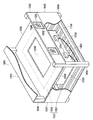
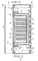
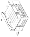
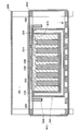
- FIG. 1 and 2 are schematic views of the battery housing structure of the first embodiment. 1 is a perspective view, and FIG. 2 is a cross-sectional view.
- the module battery 1002 is housed in the module battery housing shelf 1004 as shown in FIGS.
- the module battery 1002 may be housed in a structure that cannot be called a shelf. More generally, module battery 1002 is housed in a battery housing.
- the unit cell 1006, the heater 1008, and the sand 1010 are accommodated in the container 1012, the electrode terminal 1014 passes through the side wall 1104 of the box 1024 of the container 1012, and the unit cell 1006 and the electrode terminal are inside the container 1012. 1014 is electrically connected to the wiring 1016.
- Other storage items such as a temperature sensor may be stored in the container 1012.
- the module battery 1002 is an assembly of the unit cell 1006 and its accompanying products.
- the module battery 1002 is charged / discharged via the electrode terminal 1014.
- the container 1012 desirably has a rectangular parallelepiped shape or a rectangular parallelepiped shape that is convenient for accommodation, but may have another three-dimensional shape.
- the unit cell 1006 is a sodium-sulfur battery.
- the temperature inside the container 1012 is adjusted by the heater 1008 and maintained at a temperature at which the sodium-sulfur battery operates.
- the container 1012 has a structure in which a lid 1026 is placed over the opening of the box 1024.
- the opening of the box 1024 is closed by the top wall 1100 of the lid 1026.
- the module battery storage shelf 1004 has a structure in which a top plate 1030, a side plate 1032 and a bottom plate 1036 are attached to a skeleton 1038.
- the top plate 1030, the side plate 1032 and the bottom plate 1036 surround the space SP1 in which the module battery 1002 is accommodated.
- the module battery storage shelf 1004 has a structure in which the side plate 1040 is attached to the skeleton 1038.
- the side plate 1040 surrounds the space SP2 that is the exhaust heat destination.
- the space SP2 of the exhaust heat destination may be set outside the module battery storage shelf 1004, and the heat may be exhausted directly to the outside of the module battery storage shelf 1004.
- the top plate 1030, the side plate 1032, the bottom plate 1036, and the side plate 1040 are typically made of metal or alloy, but may be made of other materials.
- the top wall 1100 of the lid body 1026 is a solid body, and the side walls 1102 of the lid body 1026 and the side walls 1104 and the bottom wall 1106 of the box body 1024 are hollow bodies.
- the hollow part 1108 of the side wall 1102 of the lid 1026 and the side wall 1104 of the box 1024 and the hollow part 1110 of the bottom wall 1106 are decompressed. Therefore, the top wall 1100 of the lid 1026 does not have a vacuum heat insulating structure, and the side wall 1102 of the lid 1026 and the side walls 1104 and the bottom wall 1106 of the box 1024 have a vacuum heat insulating structure.
- the thermal conductivity of the top wall 1100 of the lid 1026 is relatively high, and the thermal conductivity of the side wall 1102 of the lid 1026 and the side walls 1104 and bottom wall 1106 of the box 1024 is relatively low. Thereby, heat is exhausted from the inside of the container 1012 to the outside mainly through the top wall 1100 of the lid 1026.
- the top plate 1030 has a larger planar shape than the outer surface 1200 of the top wall 1100 of the lid 1026.
- the first portion 1202 occupying the center of the top plate 1030 overlaps the outer surface 1200 of the top wall 1100 of the lid 1026, and the second portion 1204 occupying the periphery of the top plate 1030 is from the outer surface 1200 of the top wall 1100 of the lid 1026. Stick out.
- the second portion 1204 surrounds the first portion 1202.
- One shape object and another shape object "overlapping" means that the planar shape of one shape object is the same as that of the other shape object, and the plane position of the one shape object and the other shape object It is said that the plane position matches, and it does not matter whether there is direct contact between one shape object and another shape object.
- An opening 1206 is formed in the first portion 1202.
- the opening 1206 has a smaller planar shape than the outer surface 1200 of the top wall 1100 of the lid 1026. Opening 1206 is formed away from second portion 1204.
- the first main surface 1210 of the top plate 1030 is in direct contact with the periphery of the outer surface 1200 of the top wall 1100 of the lid 1026 at the non-opening portion 1208 other than the opening 1206 of the first portion 1202, and the second portion At 1204, the container 1012 is moved away.
- the 2nd main surface 1214 of the top plate 1030 is exposed to the space SP2 of the exhaust heat destination.
- the center of the outer surface 1200 of the top wall 1100 of the lid 1026 is exposed to the space SP2 of the exhaust heat destination, and the heat exhausted through the top wall 1100 of the lid 1026 is Heat is exhausted mainly to the exhaust heat destination space SP2 through the opening 1206 formed in the first portion 1202.
- the space SP1 in which the module battery 1002 is accommodated is separated from the space SP2 in the exhaust heat destination by the second portion 1204, and it is difficult for heat to flow from the space SP2 in the exhaust heat destination to the space SP1 in which the module battery 1002 is accommodated.
- the temperature around the electrode terminal 1014 is unlikely to rise. If the temperature around the electrode terminal 1014 is less likely to rise, the temperature around the electrode terminal 1014 can be easily made lower than the allowable temperature even if the air conditioning equipment is omitted or the capacity of the air conditioning equipment is low.
- the first main surface 1210 does not contact the outer surface 1200 of the top wall 1100 in the entire non-opening portion 1208.
- the first main surface 1210 is allowed to contact the outer surface 1200 of the top wall 1100 in a ring shape in a part of the non-opening portion 1208.
- the second portion 1204 may be a solid body, but may be a hollow body suitable for inhibition of heat inflow.
- the outer surface 1200 of the top wall 1100 faces upward in the vertical direction. Thereby, the exhaust heat from the top wall 1100 is hardly transmitted to the periphery of the electrode terminal 1014, and the temperature around the electrode terminal 1014 is not easily increased.
- the wall other than the top wall 1100 of the lid 1026 may be a wall having relatively high thermal conductivity (hereinafter referred to as “high thermal conductivity wall”), and the side wall 1102 of the lid 1026 and the side wall 1104 and bottom of the box 1024
- a wall other than the wall 1106 may be a wall having relatively low thermal conductivity (hereinafter referred to as “low thermal conductive wall”).
- the electrode terminal 1014 penetrates the low heat conducting wall.
- a plate having a larger planar shape than the outer surface of the high heat conducting wall is attached to the skeleton 1038.
- the first part of the plate overlaps with the outer surface of the high heat transfer wall, and the second part of the plate protrudes from the outer surface of the high heat transfer wall.
- the second part surrounds the first part.
- An opening is formed in the first portion.
- the opening has a planar shape smaller than the outer surface of the high heat conducting wall.
- the opening is formed away from the second portion.
- the first main surface of the plate is in direct contact with the periphery of the outer surface of the high thermal conductivity wall at the non-opening other than the opening of the first portion, and is separated from the container 1012 at the second portion.
- the 2nd main surface of a board is exposed to space SP2 of a waste heat destination.
- the high heat conduction wall is provided above the container 1012 in the vertical direction, and the low heat conduction wall is provided below the container 1012 in the vertical direction.
- the entire wall of the lid body 1026 becomes a high heat conduction wall, and the whole wall of the box body 1024 becomes a low heat conduction wall.
- the exhaust heat from the high heat conduction wall is not easily transmitted to the periphery of the electrode terminal 1014, and the temperature around the electrode terminal 1014 is hardly increased.
- the difference between the thermal conductivity of the high thermal conductivity wall and the thermal conductivity of the low thermal conductivity wall may be caused by other than the presence or absence of the vacuum heat insulating structure.
- the vacuum degree of the hollow part of the high heat conduction wall is relatively low
- the vacuum degree of the hollow part of the low heat conduction wall is relatively high. It will be lost.
- the high heat conduction wall and the low heat conduction wall do not have a vacuum heat insulation structure
- the high heat conduction wall is made of a material having a relatively high heat conductivity
- the low heat conduction wall is made of a material having a relatively low heat conductivity. Become.
- the unit cell 1006 accommodated in the container 1012 may be singular or plural.
- the waste heat destination space SP2 is desirably an open space.
- An open space is a space that is connected to an external space and ventilated.
- a ventilation mechanism 1300 such as a ventilation fan for forcibly ventilating the exhaust heat destination space SP2 is provided in the module battery housing shelf 1004.
- a ventilation mechanism 1300 such as a ventilation fan for forcibly ventilating the exhaust heat destination space SP2
- a dustproof filter 1304 is desirably provided in the ventilation port 1302 of the module battery storage shelf 1004. Thereby, the penetration
- the exhaust heat destination space SP2 may be a sealed space.
- the sealed space is a space that is not connected to the external space and is not ventilated.
- the heater 1008 is preferably installed along the inner surface of the low thermal conductive wall, and more preferably is installed along the inner surface of the low thermal conductive wall opposite the high thermal conductive wall.
- the heater 1008 is preferably installed along the inner surface of all or part of the side wall 1104 and the bottom wall 1106 of the box 1024, and more preferably the box A heater 1008 is installed along the inner surface of the bottom wall 1106 of the body 1024.
- the unit cell 1006 is arranged between the high heat conduction wall and the heater 1008, and the heat generated by the heater 1008 is suppressed from being exhausted outside the container 1012 without contributing to the heating of the unit cell 1006. The power consumption of the heater 1008 is reduced.
- the electrical component 1400 other than the electrode terminal 1014 is desirably installed in the space SP1 in which the module battery 1002 is accommodated. This makes it difficult for the temperature around the electrical component 1400 to rise.
- the electrical component 1400 includes a cable, an electric circuit board, and the like.
- the upper cover 1500 is put on the upper end of the module battery storage shelf 1004.
- the upper cover 1500 may be omitted.
- the skeleton 1038 is provided with a support 1600 having a bar shape and horizontally supported.
- the top plate 1030 is placed on the stay 1600 and supported by the stay 1600 at a support position 1602 away from the first portion 1202.
- the second portion 1204 desirably has elasticity.
- the second embodiment relates to a battery housing structure used in place of the battery housing structure of the first embodiment.
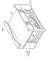
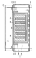
- FIG. 3 and 4 are schematic views of the battery housing structure of the second embodiment. 3 is a perspective view, and FIG. 4 is a cross-sectional view.
- the battery housing structure 2000 of the second embodiment is different from the top plate 1030 in which the opening 1206 is formed, except that a top plate 2030 in which no opening is formed is used.
- This is the same as the battery housing structure 1000 of the first embodiment.
- the same components as those of the first embodiment are denoted by the same reference numerals as those of the first embodiment, and items different from the first embodiment are mainly referred to. .
- the description of the first embodiment can be applied to matters not mentioned in the description of the second embodiment.
- the top plate 2030 has a larger planar shape than the outer surface 1200 of the top wall 1100 of the lid 1026.
- a first portion 2202 occupying the center of the top plate 2030 overlaps the outer surface 1200 of the top wall 1100 of the lid body 1026, and a second portion 2204 occupying the periphery of the top plate 2030 is from the outer surface 1200 of the top wall 1100 of the lid body 1026. Stick out.
- the second portion 2204 surrounds the first portion 2202.
- the first main surface 2210 of the top plate 2030 is in direct contact with the entire outer surface 1200 of the top wall 1100 of the lid 1026 in the entire first portion 2202 and is separated from the container 1012 in the second portion 2204.
- the second main surface 2214 of the top plate 2030 is exposed to the space SP2 where the heat is discharged.
- the heat exhausted through the top wall 1100 is exhausted mainly to the exhaust heat destination space SP2 through the first portion 2202.
- the space SP1 in which the module battery 1002 is housed and the exhaust heat destination space SP2 are separated by the second portion 2204, so that heat does not easily flow from the exhaust heat destination space SP2 into the space SP1 in which the module battery 1002 is housed.
- the temperature around the electrode terminal 1014 is unlikely to rise.
- the skeleton 1038 is provided with a stay 2600 that has a rod shape and is horizontally supported.
- the top plate 2030 is placed on the stay 2600 and supported by the stay 2600 at a support position 2602 away from the first portion 2202.
- the second portion 2204 is desirably elastic. Since the outer surface 1200 of the top wall 1100 of the lid 1026 faces upward in the vertical direction, the second portion 2204 is deformed by this, the top plate 2030 is flexed downward, and the first portion 2202 is the lid. 1026 is pressed against the ceiling wall 1100, the thermal resistance at the interface between the ceiling wall 1100 and the ceiling plate 2030 is reduced, and the heat is efficiently exhausted.
- the third embodiment relates to a battery housing structure used in place of the battery housing structure of the first embodiment.
- FIG. 5 and 6 are schematic views of the battery housing structure of the third embodiment. 5 is a perspective view, and FIG. 6 is a cross-sectional view.
- a top plate 3030 having no opening is used instead of the top plate 1030 having the opening 1206, and the top wall 3100 and the first portion 3202 of the top plate 3030 are used. Except that a heat transfer medium 3700 is sandwiched between them and a top wall 3100 in which a rib 3702 is formed instead of the top wall 1100 having a flat outer surface 1200 is used, as in the battery housing structure 1000 of the first embodiment. Is. For this reason, in description of 3rd Embodiment, the same referential mark as 1st Embodiment is attached
- the description of the first embodiment can be applied to matters not mentioned in the description of the third embodiment.
- the top plate 3030 has a larger planar shape than the outer surface 3200 of the top wall 3100 of the lid 3026 of the container 3012.
- the first portion 3202 occupying the center of the top plate 3030 overlaps the outer surface 3200 of the top wall 3100 of the lid 3026, and the second portion 3204 occupying the periphery of the top plate 3030 is from the outer surface 3200 of the top wall 3100 of the lid 3026. Stick out.
- the second portion 3204 surrounds the first portion 3202.
- the first main surface 3210 of the top plate 3030 faces the outer surface 3200 of the top wall 3100 at the first portion 3202 and is separated from the container 3012 at the second portion 3204.
- the second main surface 3214 of the top plate 3030 is exposed to the space SP2 where the heat is discharged.
- the heat transfer medium 3700 is sandwiched between the top wall 3100 of the lid 3026 and the first portion 3202, and directly contacts the outer surface 3200 of the top wall 3100, and the first portion 3202 has a first plate of the top plate 3030.
- the main surface 3210 is directly contacted.
- the heat exhausted through the top wall 3100 is mainly exhausted to the exhaust heat destination space SP2 through the heat transfer medium 3700 and the first portion 3202. .
- the space SP1 in which the module battery 1002 is accommodated is separated from the space SP2 in the exhaust heat destination by the second portion 3204, so that it is difficult for heat to flow from the space SP2 in the exhaust heat destination to the space SP1 in which the module battery 1002 is accommodated.
- the temperature around the electrode terminal 1014 is unlikely to rise.
- the amount of exhaust heat is appropriately adjusted by the thermal resistance of the heat transfer medium 3700 and the temperature inside the container 3012 is appropriately adjusted.
- the thermal resistance of the heat transfer medium 3700 is adjusted by the material, the planar shape, etc. of the heat transfer medium 3700.
- the heat transfer medium 3700 may be a plate-shaped object made of a metal or an alloy, or may be an aggregate of fibers made of a metal or an alloy, for example, steel wool.
- the heat transfer medium 3700 may be a viscous material such as silicon grease.
- the number of heat transfer media 3700 may be singular or plural. When a plurality of heat transfer media 3700 are provided, the plurality of heat transfer media 3700 are desirably arranged uniformly.
- the fourth embodiment relates to a battery housing structure used in place of the battery housing structure of the first embodiment.
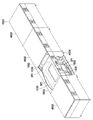
- FIG. 7 is a schematic diagram of the battery housing structure 4000 of the fourth embodiment.
- FIG. 7 is a perspective view.
- the battery housing structure 4000 of the fourth embodiment is an arrangement in which the battery housing structures 1000 of the first embodiment are arranged in the horizontal direction and the side plate 1032 between the adjacent battery housing structures 1000 is removed. It is the same as the body. For this reason, in description of 4th Embodiment, the same referential mark as 1st Embodiment is attached
- the description of the first embodiment can be applied to matters not mentioned in the description of the fourth embodiment.
- a plurality of module batteries 1002 are housed in the module battery housing shelf 4004.
- the module battery storage shelf 4004 is provided with a plurality of storage compartments 4800 similar to the battery storage structure 1000 of the first embodiment.
- Each of the plurality of housing sections 4800 has a space SP1 in which the module battery 1002 is housed and a space SP2 for exhaust heat destination.
- Each of the plurality of storage compartments 4800 stores a single module battery 1002 and is provided with a top plate 1030.
- the top plate 1030 provided in each of the plurality of accommodating sections 4800 may be combined.
- the plurality of storage compartments 4800 are arranged in a horizontal direction parallel to the top plate 1030, and the exhaust heat destination spaces SP2 belonging to each of the plurality of storage compartments 4800 are connected to each other. SP3 is formed. A space SP1 in which the module batteries 1002 belonging to each of the plurality of housing sections 4800 are housed is connected.
- the exhaust heat structure of the first embodiment is employed. Accordingly, heat is exhausted in the same manner as the exhaust heat structure of the first embodiment, except that the exhaust heat destination space SP3 is common to the plurality of module batteries 1002.
- a ventilation mechanism 1300 that forcibly ventilates the space SP2 that is the exhaust heat destination is installed.
- the installation of the ventilation mechanism 1300 in a part of the plurality of storage compartments 4800 may be omitted, the exhaust destination space SP3 common to the plurality of module batteries 1002 is ventilated by the plurality of ventilation mechanisms 1300.
- the plurality of ventilation mechanisms 1300 Even if a part of the plurality of ventilation mechanisms 1300 breaks down, ventilation does not stop completely, and redundancy is improved.
- the exhaust heat structure of the first embodiment may be replaced with the exhaust heat structure of the second embodiment or the third embodiment.
- the electrical component 1400 desirably passes through the space SP1 in which the module battery 1002 is accommodated. This makes it difficult for the temperature around the electrical component 1400 to rise.
- the fifth embodiment relates to a battery housing structure used in place of the battery housing structure of the first embodiment.
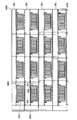
- FIG. 8 is a schematic view of the battery housing structure of the fifth embodiment.
- FIG. 8 is a sectional view.
- the battery housing structure 5000 according to the fifth embodiment includes a plurality of battery housing structures 1000 according to the first embodiment arranged in the horizontal direction and the vertical direction, and side plates 1032 between adjacent battery housing structures 1000 and It is the same as the array in which the upper cover 1500 is removed and an electrical component storage chamber 5902 is added.
- the same components as those of the first embodiment are denoted by the same reference numerals as those of the first embodiment, and items different from the first embodiment are mainly referred to. .
- the description of the first embodiment can be applied to matters not mentioned in the description of the fifth embodiment.
- a plurality of module batteries 1002 are housed in the module battery housing shelf 5004.
- the module battery storage shelf 5004 is provided with a plurality of storage compartments 5800 and an electrical component storage chamber 5902.
- Each of the plurality of housing sections 5800 has a space SP1 in which the module battery 1002 is housed and a space SP2 for exhaust heat destination.
- Each of the plurality of housing sections 5800 houses a single module battery 1002 and is provided with a top plate 1030.
- a top plate 1030 provided in each of the plurality of storage compartments 5800 arranged in the horizontal direction may be combined.
- the plurality of storage compartments 5800 are arranged in a horizontal direction parallel to the top plate 1030 and in a vertical direction perpendicular to the top plate 1030, and the exhaust heat destination spaces SP2 belonging to each of the plurality of storage compartments 5800 arranged in the horizontal direction are connected.
- a waste heat destination space SP3 common to the plurality of module batteries 1002 is formed.
- a space SP1 in which the module batteries 1002 belonging to each of the plurality of receiving sections 5800 arranged in the horizontal direction are stored is connected.
- the exhaust heat structure of the first embodiment is employed. Accordingly, heat is exhausted in the same manner as the exhaust heat structure of the first embodiment, except that the exhaust heat destination space SP3 is common to the plurality of module batteries 1002.
- a ventilation mechanism that forcibly ventilates the space SP2 that is the exhaust heat destination is installed.
- the installation of a ventilation mechanism in a part of the plurality of housing sections 5800 may be omitted, the exhaust destination space SP3 common to the plurality of module batteries 1002 is ventilated by the plurality of ventilation mechanisms. Thereby, even if a part of a plurality of ventilation mechanisms breaks down, ventilation does not stop completely, and redundancy is improved.
- the exhaust heat structure of the first embodiment may be replaced with the exhaust heat structure of the second embodiment or the third embodiment.
Landscapes
- Chemical & Material Sciences (AREA)
- Chemical Kinetics & Catalysis (AREA)
- Electrochemistry (AREA)
- General Chemical & Material Sciences (AREA)
- Engineering & Computer Science (AREA)
- Manufacturing & Machinery (AREA)
- Secondary Cells (AREA)
- Battery Mounting, Suspending (AREA)
Abstract
La présente invention se rapporte à une batterie modulaire qui est reçue sur une étagère de réception d'une batterie modulaire. Dans la batterie modulaire, une cellule électrique est reçue à l'intérieur d'un contenant. La cellule électrique est une batterie sodium-soufre. Le contenant est pourvu d'une paroi à conductivité thermique élevée, dans laquelle la conductivité thermique est relativement élevée, ainsi que d'une paroi à conductivité thermique faible, dans laquelle la conductivité thermique est relativement faible. La première partie d'une plaque recouvre la surface externe de la paroi à conductivité thermique élevée et la seconde partie de la plaque fait saillie depuis la surface externe de la paroi à conductivité thermique élevée. La seconde partie entoure la première partie. La première surface principale de la plaque est, dans la première partie, directement mise en contact avec la surface externe de la paroi à conductivité thermique élevée et est éloignée du contenant dans la seconde partie. La seconde surface principale de la plaque est exposée à l'espace dans lequel la chaleur est libérée. Une ouverture peut ou non être formée dans la première partie. Un support de transfert de chaleur peut être intercalé entre la première paroi et la première partie.
Priority Applications (4)
| Application Number | Priority Date | Filing Date | Title |
|---|---|---|---|
| JP2012555703A JP5798131B2 (ja) | 2011-02-03 | 2011-12-20 | 電池収容構造 |
| EP11857787.3A EP2672563B1 (fr) | 2011-02-03 | 2011-12-20 | Structure de logement de batterie |
| CN201180066477.4A CN103339789B (zh) | 2011-02-03 | 2011-12-20 | 电池容纳结构 |
| US13/937,489 US10141615B2 (en) | 2011-02-03 | 2013-07-09 | Battery housing structure |
Applications Claiming Priority (2)
| Application Number | Priority Date | Filing Date | Title |
|---|---|---|---|
| JP2011021599 | 2011-02-03 | ||
| JP2011-021599 | 2011-02-03 |
Related Child Applications (1)
| Application Number | Title | Priority Date | Filing Date |
|---|---|---|---|
| US13/937,489 Continuation US10141615B2 (en) | 2011-02-03 | 2013-07-09 | Battery housing structure |
Publications (1)
| Publication Number | Publication Date |
|---|---|
| WO2012105137A1 true WO2012105137A1 (fr) | 2012-08-09 |
Family
ID=46602367
Family Applications (1)
| Application Number | Title | Priority Date | Filing Date |
|---|---|---|---|
| PCT/JP2011/079489 Ceased WO2012105137A1 (fr) | 2011-02-03 | 2011-12-20 | Structure de logement de batterie |
Country Status (5)
| Country | Link |
|---|---|
| US (1) | US10141615B2 (fr) |
| EP (1) | EP2672563B1 (fr) |
| JP (1) | JP5798131B2 (fr) |
| CN (1) | CN103339789B (fr) |
| WO (1) | WO2012105137A1 (fr) |
Cited By (3)
| Publication number | Priority date | Publication date | Assignee | Title |
|---|---|---|---|---|
| WO2013111426A1 (fr) * | 2012-01-24 | 2013-08-01 | 日本碍子株式会社 | Appareil de stockage d'énergie et procédé de fonctionnement de l'appareil de stockage d'énergie |
| WO2014050660A1 (fr) * | 2012-09-25 | 2014-04-03 | 日本碍子株式会社 | Dispositif de stockage de puissance |
| JP2016513779A (ja) * | 2013-03-11 | 2016-05-16 | デーナ、オータモウティヴ、システィムズ、グループ、エルエルシー | ディファレンシャルキャリアエレクトロニクスパッケージ |
Families Citing this family (15)
| Publication number | Priority date | Publication date | Assignee | Title |
|---|---|---|---|---|
| FR3044512B1 (fr) * | 2015-11-30 | 2018-01-05 | Lancey Energy Storage | Appareil de chauffage incluant des batteries de stockage de l'energie electrique |
| WO2018023050A1 (fr) | 2016-07-29 | 2018-02-01 | Crynamt Management Llc | Bloc-batterie haute densité |
| WO2018022964A1 (fr) | 2016-07-29 | 2018-02-01 | Crynamt Management Llc | Blocs-batteries ayant des éléments structuraux pour améliorer la gestion thermique |
| US11757149B1 (en) | 2016-09-20 | 2023-09-12 | Apple Inc. | Battery liquid quench system and methods of manufacture thereof |
| USD806016S1 (en) * | 2016-10-10 | 2017-12-26 | K2 Energy Solutions, Inc. | Battery housing |
| US10923788B1 (en) | 2016-11-30 | 2021-02-16 | Apple Inc. | Directed quench systems and components |
| US11870092B1 (en) | 2017-02-01 | 2024-01-09 | Apple Inc. | On-board vent gas abatement |
| DE102017213887A1 (de) * | 2017-08-09 | 2019-02-14 | Audi Ag | Batteriemodulanordnung, Batterie, Kraftfahrzeug und Verfahren zum Anordnen zumindest eines Batteriemoduls in einer Modulaufnahmeeinrichtung |
| US10991924B2 (en) * | 2017-10-19 | 2021-04-27 | Tiveni Mergeco, Inc. | Pressure equalization between battery module compartments of an energy storage system and external environment |
| JP6587670B2 (ja) * | 2017-11-20 | 2019-10-09 | 本田技研工業株式会社 | バッテリモジュール及び電動車両 |
| US11469471B1 (en) | 2018-02-02 | 2022-10-11 | Apple Inc. | Battery pack heat dispensing systems |
| WO2020184332A1 (fr) * | 2019-03-14 | 2020-09-17 | 日本碍子株式会社 | Récipient de batterie de stockage |
| US11764431B2 (en) | 2020-10-22 | 2023-09-19 | Apple Inc. | Battery pack structures and systems |
| US12009655B2 (en) | 2021-09-15 | 2024-06-11 | Apple Inc. | Switchable pyro fuse |
| KR20240077122A (ko) * | 2022-11-24 | 2024-05-31 | 에스케이온 주식회사 | 배터리 팩 |
Citations (4)
| Publication number | Priority date | Publication date | Assignee | Title |
|---|---|---|---|---|
| JPH11185801A (ja) * | 1997-12-25 | 1999-07-09 | Hitachi Ltd | 高温ナトリウム二次電池モジュールおよびその運転方法 |
| JP2004047208A (ja) | 2002-07-10 | 2004-02-12 | Ngk Insulators Ltd | 集合電池用断熱容器 |
| JP2004055373A (ja) * | 2002-07-22 | 2004-02-19 | Ngk Insulators Ltd | ナトリウム−硫黄電池及び温度調節方法 |
| JP2008226488A (ja) | 2007-03-08 | 2008-09-25 | Ngk Insulators Ltd | ナトリウム−硫黄電池用パッケージ |
Family Cites Families (12)
| Publication number | Priority date | Publication date | Assignee | Title |
|---|---|---|---|---|
| DE3119409A1 (de) * | 1981-05-15 | 1982-12-09 | Brown, Boveri & Cie Ag, 6800 Mannheim | "hochtemperaturbatterie" |
| JP2703484B2 (ja) * | 1993-03-29 | 1998-01-26 | 日本碍子株式会社 | 高温電池用断熱容器 |
| GB2277830B (en) * | 1993-05-04 | 1996-10-23 | Programme 3 Patent Holdings | High temperature storage battery |
| JPH0817464A (ja) * | 1994-07-04 | 1996-01-19 | Hitachi Ltd | 二次電池電力貯蔵システム及び真空断熱容器 |
| US5578393A (en) * | 1995-03-10 | 1996-11-26 | United States Advanced Battery Consortium | Thermal contact sheet for high temperature batteries |
| JPH09330738A (ja) * | 1996-06-11 | 1997-12-22 | Hitachi Ltd | ナトリウム−硫黄電池モジュール |
| JP2000021364A (ja) * | 1998-06-30 | 2000-01-21 | Ngk Insulators Ltd | 集合電池用真空断熱容器 |
| JP2000048857A (ja) * | 1998-07-27 | 2000-02-18 | Ngk Insulators Ltd | 集合電池用真空断熱容器 |
| US20040042178A1 (en) * | 2002-09-03 | 2004-03-04 | Vadim Gektin | Heat spreader with surface cavity |
| KR101093959B1 (ko) * | 2010-02-04 | 2011-12-15 | 에스비리모티브 주식회사 | 전지 모듈의 방열 장치 |
| WO2011142199A1 (fr) * | 2010-05-12 | 2011-11-17 | 日本碍子株式会社 | Module de batterie secondaire |
| JP3177969U (ja) * | 2012-06-14 | 2012-08-23 | 日本碍子株式会社 | ナトリウム硫黄電池パッケージ |
-
2011
- 2011-12-20 EP EP11857787.3A patent/EP2672563B1/fr not_active Not-in-force
- 2011-12-20 CN CN201180066477.4A patent/CN103339789B/zh not_active Expired - Fee Related
- 2011-12-20 JP JP2012555703A patent/JP5798131B2/ja not_active Expired - Fee Related
- 2011-12-20 WO PCT/JP2011/079489 patent/WO2012105137A1/fr not_active Ceased
-
2013
- 2013-07-09 US US13/937,489 patent/US10141615B2/en not_active Expired - Fee Related
Patent Citations (4)
| Publication number | Priority date | Publication date | Assignee | Title |
|---|---|---|---|---|
| JPH11185801A (ja) * | 1997-12-25 | 1999-07-09 | Hitachi Ltd | 高温ナトリウム二次電池モジュールおよびその運転方法 |
| JP2004047208A (ja) | 2002-07-10 | 2004-02-12 | Ngk Insulators Ltd | 集合電池用断熱容器 |
| JP2004055373A (ja) * | 2002-07-22 | 2004-02-19 | Ngk Insulators Ltd | ナトリウム−硫黄電池及び温度調節方法 |
| JP2008226488A (ja) | 2007-03-08 | 2008-09-25 | Ngk Insulators Ltd | ナトリウム−硫黄電池用パッケージ |
Non-Patent Citations (1)
| Title |
|---|
| See also references of EP2672563A4 |
Cited By (7)
| Publication number | Priority date | Publication date | Assignee | Title |
|---|---|---|---|---|
| WO2013111426A1 (fr) * | 2012-01-24 | 2013-08-01 | 日本碍子株式会社 | Appareil de stockage d'énergie et procédé de fonctionnement de l'appareil de stockage d'énergie |
| JPWO2013111426A1 (ja) * | 2012-01-24 | 2015-05-11 | 日本碍子株式会社 | 電力貯蔵装置及び電力貯蔵装置の運転方法 |
| US9859592B2 (en) | 2012-01-24 | 2018-01-02 | Ngk Insulators, Ltd. | Power storage apparatus and method of operating power storage apparatus |
| WO2014050660A1 (fr) * | 2012-09-25 | 2014-04-03 | 日本碍子株式会社 | Dispositif de stockage de puissance |
| JPWO2014050660A1 (ja) * | 2012-09-25 | 2016-08-22 | 日本碍子株式会社 | 電力貯蔵装置 |
| US10541405B2 (en) | 2012-09-25 | 2020-01-21 | Ngk Insulators, Ltd. | Power storage apparatus |
| JP2016513779A (ja) * | 2013-03-11 | 2016-05-16 | デーナ、オータモウティヴ、システィムズ、グループ、エルエルシー | ディファレンシャルキャリアエレクトロニクスパッケージ |
Also Published As
| Publication number | Publication date |
|---|---|
| JP5798131B2 (ja) | 2015-10-21 |
| EP2672563B1 (fr) | 2018-02-21 |
| EP2672563A1 (fr) | 2013-12-11 |
| JPWO2012105137A1 (ja) | 2014-07-03 |
| US10141615B2 (en) | 2018-11-27 |
| CN103339789B (zh) | 2015-06-24 |
| US20130295428A1 (en) | 2013-11-07 |
| CN103339789A (zh) | 2013-10-02 |
| EP2672563A4 (fr) | 2016-12-28 |
Similar Documents
| Publication | Publication Date | Title |
|---|---|---|
| JP5798131B2 (ja) | 電池収容構造 | |
| CN101924259B (zh) | 具有温差控制功能的动力电池双循环风冷散热方法和装置 | |
| US9908431B2 (en) | Battery counterweight system | |
| JP5067171B2 (ja) | 電気化学蓄電素子モジュール | |
| JP5751261B2 (ja) | 熱電発電ユニット | |
| CN102792484B (zh) | 用于机动车的电池 | |
| KR101865002B1 (ko) | 온습도 통합관리 및 제어기능을 갖춘 자동제어반 | |
| JP6437546B2 (ja) | 複数のエネルギ貯蔵アセンブリを備えるエネルギ貯蔵モジュール | |
| JPWO2011092773A1 (ja) | 電池モジュール | |
| WO2016197797A1 (fr) | Module de batterie et station de base pourvue d'un module de batterie | |
| CN105742751B (zh) | 电池组 | |
| TWI669843B (zh) | 具備二次電池之發電裝置 | |
| JP5896833B2 (ja) | 屋外設置機器の製造方法およびインバータ装置の製造方法 | |
| JP5971748B2 (ja) | 蓄電装置及び蓄電システム | |
| NL2015268B1 (en) | Solar power system | |
| JP5936114B2 (ja) | 蓄電装置 | |
| WO2008142414A1 (fr) | Puits de chaleur condensateur | |
| KR102203651B1 (ko) | 에너지 저장 장치를 구비한 냉장고 | |
| JP5870290B2 (ja) | 蓄電装置 | |
| JP2024001660A (ja) | 蓄電システム | |
| JP3224790U (ja) | 蓄電池及び蓄電池システム | |
| JP2016021817A (ja) | 電力変換装置 | |
| CN220382189U (zh) | 保温电池包 | |
| JP5159077B2 (ja) | 燃料電池 | |
| CN224218696U (zh) | 逆变器及电气设备 |
Legal Events
| Date | Code | Title | Description |
|---|---|---|---|
| 121 | Ep: the epo has been informed by wipo that ep was designated in this application |
Ref document number: 11857787 Country of ref document: EP Kind code of ref document: A1 |
|
| ENP | Entry into the national phase |
Ref document number: 2012555703 Country of ref document: JP Kind code of ref document: A |
|
| WWE | Wipo information: entry into national phase |
Ref document number: 2011857787 Country of ref document: EP |
|
| NENP | Non-entry into the national phase |
Ref country code: DE |