WO2013111426A1 - Appareil de stockage d'énergie et procédé de fonctionnement de l'appareil de stockage d'énergie - Google Patents
Appareil de stockage d'énergie et procédé de fonctionnement de l'appareil de stockage d'énergie Download PDFInfo
- Publication number
- WO2013111426A1 WO2013111426A1 PCT/JP2012/079481 JP2012079481W WO2013111426A1 WO 2013111426 A1 WO2013111426 A1 WO 2013111426A1 JP 2012079481 W JP2012079481 W JP 2012079481W WO 2013111426 A1 WO2013111426 A1 WO 2013111426A1
- Authority
- WO
- WIPO (PCT)
- Prior art keywords
- battery
- chamber
- power storage
- storage device
- air
- Prior art date
- Legal status (The legal status is an assumption and is not a legal conclusion. Google has not performed a legal analysis and makes no representation as to the accuracy of the status listed.)
- Ceased
Links
Images



Classifications
-
- H—ELECTRICITY
- H01—ELECTRIC ELEMENTS
- H01M—PROCESSES OR MEANS, e.g. BATTERIES, FOR THE DIRECT CONVERSION OF CHEMICAL ENERGY INTO ELECTRICAL ENERGY
- H01M10/00—Secondary cells; Manufacture thereof
- H01M10/36—Accumulators not provided for in groups H01M10/05-H01M10/34
- H01M10/39—Accumulators not provided for in groups H01M10/05-H01M10/34 working at high temperature
- H01M10/3909—Sodium-sulfur cells
-
- H—ELECTRICITY
- H01—ELECTRIC ELEMENTS
- H01M—PROCESSES OR MEANS, e.g. BATTERIES, FOR THE DIRECT CONVERSION OF CHEMICAL ENERGY INTO ELECTRICAL ENERGY
- H01M10/00—Secondary cells; Manufacture thereof
- H01M10/42—Methods or arrangements for servicing or maintenance of secondary cells or secondary half-cells
- H01M10/48—Accumulators combined with arrangements for measuring, testing or indicating the condition of cells, e.g. the level or density of the electrolyte
- H01M10/486—Accumulators combined with arrangements for measuring, testing or indicating the condition of cells, e.g. the level or density of the electrolyte for measuring temperature
-
- H—ELECTRICITY
- H01—ELECTRIC ELEMENTS
- H01M—PROCESSES OR MEANS, e.g. BATTERIES, FOR THE DIRECT CONVERSION OF CHEMICAL ENERGY INTO ELECTRICAL ENERGY
- H01M10/00—Secondary cells; Manufacture thereof
- H01M10/60—Heating or cooling; Temperature control
- H01M10/61—Types of temperature control
- H01M10/613—Cooling or keeping cold
-
- H—ELECTRICITY
- H01—ELECTRIC ELEMENTS
- H01M—PROCESSES OR MEANS, e.g. BATTERIES, FOR THE DIRECT CONVERSION OF CHEMICAL ENERGY INTO ELECTRICAL ENERGY
- H01M10/00—Secondary cells; Manufacture thereof
- H01M10/60—Heating or cooling; Temperature control
- H01M10/65—Means for temperature control structurally associated with the cells
- H01M10/655—Solid structures for heat exchange or heat conduction
-
- H—ELECTRICITY
- H01—ELECTRIC ELEMENTS
- H01M—PROCESSES OR MEANS, e.g. BATTERIES, FOR THE DIRECT CONVERSION OF CHEMICAL ENERGY INTO ELECTRICAL ENERGY
- H01M10/00—Secondary cells; Manufacture thereof
- H01M10/60—Heating or cooling; Temperature control
- H01M10/65—Means for temperature control structurally associated with the cells
- H01M10/656—Means for temperature control structurally associated with the cells characterised by the type of heat-exchange fluid
- H01M10/6561—Gases
- H01M10/6563—Gases with forced flow, e.g. by blowers
-
- H—ELECTRICITY
- H01—ELECTRIC ELEMENTS
- H01M—PROCESSES OR MEANS, e.g. BATTERIES, FOR THE DIRECT CONVERSION OF CHEMICAL ENERGY INTO ELECTRICAL ENERGY
- H01M10/00—Secondary cells; Manufacture thereof
- H01M10/60—Heating or cooling; Temperature control
- H01M10/65—Means for temperature control structurally associated with the cells
- H01M10/658—Means for temperature control structurally associated with the cells by thermal insulation or shielding
-
- H—ELECTRICITY
- H01—ELECTRIC ELEMENTS
- H01M—PROCESSES OR MEANS, e.g. BATTERIES, FOR THE DIRECT CONVERSION OF CHEMICAL ENERGY INTO ELECTRICAL ENERGY
- H01M50/00—Constructional details or processes of manufacture of the non-active parts of electrochemical cells other than fuel cells, e.g. hybrid cells
- H01M50/20—Mountings; Secondary casings or frames; Racks, modules or packs; Suspension devices; Shock absorbers; Transport or carrying devices; Holders
- H01M50/204—Racks, modules or packs for multiple batteries or multiple cells
-
- H—ELECTRICITY
- H01—ELECTRIC ELEMENTS
- H01M—PROCESSES OR MEANS, e.g. BATTERIES, FOR THE DIRECT CONVERSION OF CHEMICAL ENERGY INTO ELECTRICAL ENERGY
- H01M50/00—Constructional details or processes of manufacture of the non-active parts of electrochemical cells other than fuel cells, e.g. hybrid cells
- H01M50/20—Mountings; Secondary casings or frames; Racks, modules or packs; Suspension devices; Shock absorbers; Transport or carrying devices; Holders
- H01M50/253—Mountings; Secondary casings or frames; Racks, modules or packs; Suspension devices; Shock absorbers; Transport or carrying devices; Holders adapted for specific cells, e.g. electrochemical cells operating at high temperature
-
- H—ELECTRICITY
- H01—ELECTRIC ELEMENTS
- H01M—PROCESSES OR MEANS, e.g. BATTERIES, FOR THE DIRECT CONVERSION OF CHEMICAL ENERGY INTO ELECTRICAL ENERGY
- H01M10/00—Secondary cells; Manufacture thereof
- H01M10/60—Heating or cooling; Temperature control
- H01M10/62—Heating or cooling; Temperature control specially adapted for specific applications
- H01M10/627—Stationary installations, e.g. power plant buffering or backup power supplies
-
- Y—GENERAL TAGGING OF NEW TECHNOLOGICAL DEVELOPMENTS; GENERAL TAGGING OF CROSS-SECTIONAL TECHNOLOGIES SPANNING OVER SEVERAL SECTIONS OF THE IPC; TECHNICAL SUBJECTS COVERED BY FORMER USPC CROSS-REFERENCE ART COLLECTIONS [XRACs] AND DIGESTS
- Y02—TECHNOLOGIES OR APPLICATIONS FOR MITIGATION OR ADAPTATION AGAINST CLIMATE CHANGE
- Y02E—REDUCTION OF GREENHOUSE GAS [GHG] EMISSIONS, RELATED TO ENERGY GENERATION, TRANSMISSION OR DISTRIBUTION
- Y02E60/00—Enabling technologies; Technologies with a potential or indirect contribution to GHG emissions mitigation
- Y02E60/10—Energy storage using batteries
Definitions
- the present invention relates to a power storage device and a method for operating the power storage device.
- NaS batteries Sodium-sulfur batteries
- a container heat insulating container
- the temperature inside the container is maintained at a high temperature.
- a battery in which a single cell is housed in a container is further converted into an unsealed container (package). May be housed.
- the heat discharged from the inside of the container to the outside is discharged from the inside of the non-sealed container to the outside by an air flow passing through the inside of the non-sealed container.
- An object of the present invention is to provide an electric power storage device that is inexpensive in operation and maintenance, is appropriately maintained in internal temperature, and is not easily affected by outside air such as salt damage.
- the present invention is directed to a power storage device.
- a battery In the first aspect of the present invention, a battery, an external charging / discharging path, a sealed container, an intake path formation, an exhaust path formation, a generation mechanism, a determination unit, and a generation control unit are provided in the power storage device.
- the battery is equipped with a container, a single cell of sodium-sulfur battery and a charge / discharge path in the battery.
- the container has an outer wall and a heat transfer wall.
- a cell chamber and an air chamber are formed inside the container.
- the heat transfer wall separates the unit cell chamber and the air chamber.
- the single battery and the charge / discharge path in the battery are accommodated in the single battery chamber.
- the external battery charging / discharging path and the internal charging / discharging path are electrically connected.
- the sealed container accommodates the battery and the battery charge / discharge path.
- the intake path formed in the intake path formation is from the outside of the sealed container to the air chamber.
- the exhaust path formed in the exhaust path forming material extends from the air chamber to the outside of the sealed container.
- the generating mechanism generates an air flow that sequentially flows through the intake path, the air chamber, and the exhaust path.
- the determination unit determines whether or not the single cell room needs to be cooled.
- the generation control unit controls the generation mechanism so as to generate an air flow when the unit cell chamber needs to be cooled and not generate an air flow when the unit cell chamber does not need to be cooled.
- the second aspect of the present invention adds further matters to the first aspect of the present invention.
- a first temperature sensor is provided in the battery.
- the first temperature sensor is accommodated in the single cell chamber.
- the determination unit determines that the single cell chamber needs to be cooled when the temperature increase measured by the first temperature sensor is equal to or higher than the reference.
- the third aspect of the present invention adds further matters to the second aspect of the present invention.
- the second temperature sensor and the flow rate control unit are provided in the power storage device.
- the second temperature sensor is disposed outside the sealed container.
- the flow rate control unit controls the generation mechanism so that the flow rate of the air flow increases as the temperature measured by the second temperature sensor increases.
- the fourth aspect of the present invention adds further matters to any one of the first to third aspects of the present invention.
- a heat insulating material is further provided in the battery.
- the heat insulating material and the air chamber face each other across the outer wall.
- the fifth aspect of the present invention adds further matters to any one of the first to fourth aspects of the present invention.
- an accessory device is provided in the power storage device.
- a battery room and an accessory room are formed inside the sealed container.
- the battery is accommodated in the battery chamber.
- the accessory device is accommodated in the accessory device room.
- the sealed container has a partition wall.
- the partition wall separates the battery chamber and the accessory device chamber.
- the sixth aspect of the present invention adds further matters to the fifth aspect of the present invention.
- the exhaust path does not go through the accessory device room.
- the seventh aspect of the present invention adds further matters to any one of the first to sixth aspects of the present invention.
- two or more single cells are arranged in a direction parallel to the air chamber.
- the present invention is also directed to a method for operating a power storage device.
- the ability to discharge heat from the single cell chamber to the outside of the sealed container is maintained even when the temperature of the outside air is high. The temperature of the cell room is properly maintained.
- heat transfer from the single cell chamber to the inside of the sealed container is suppressed.
- the temperature inside the sealed container is properly maintained.
- the transfer of heat from the battery room to the accessory room is suppressed.
- the temperature of the accessory room is maintained properly.
- the transfer of heat from the exhaust path to the accessory room is suppressed.
- the temperature of the accessory room is maintained properly.
- two or more single cells are uniformly dissipated. It is difficult for two or more cells to vary.
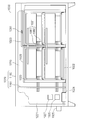
- FIGS. 1 and 2 illustrate a preferred embodiment of the power storage device.
- FIG. 1 is a front view.
- FIG. 2 is a rear view.
- the schematic diagrams of FIGS. 3 and 4 show a module battery.
- FIG. 3 is a perspective view.
- FIG. 4 is a cross-sectional view.
- the block diagram of FIG. 5 shows a controller and the like.
- the power storage device stores electric power in a sodium-sulfur battery (NaS battery).
- the power storage device is preferably connected to a power system, and is used for adjustment of power supply and demand, prevention of power failure, and the like.
- the power storage apparatus 1000 includes a module battery 1020, a bus bar 1021 outside the module battery, an intake pipe 1022, an exhaust pipe 1023, a blower 1024, an external temperature sensor 1025, an accessory device 1026, and a controller 1027.
- the battery stand 1028 and the sealed container 1029 are provided.
- the sealed container 1029 includes an outer wall 1160 and a partition wall 1161.
- the bus bar 1021 outside the module battery includes inter-battery wiring 1180 and non-battery wiring 1181.
- the module battery 1020 includes a NaS battery cell 1040, a bus bar 1041 in the module battery, a heater 1042, sand 1043, a module battery terminal 1044, an internal temperature sensor 1045, a heat insulating container 1046, and A heat insulating material 1047 is provided.
- the heat insulating container 1046 includes a box 1060 and a lid 1061.
- the box 1060 includes an outer wall 1080.
- the outer wall 1080 of the box 1060 includes a bottom wall 1100 and a side wall 1101.
- the lid body 1061 includes an outer wall 1120 and a heat transfer wall 1121.
- the outer wall 1120 of the lid body 1061 includes a top wall 1140 and a side wall 1141.
- the controller 1027 includes a charge / discharge control unit 1200, a heater control unit 1201, a determination unit 1202, a generation control unit 1203, and a flow rate control unit 1204.
- Components other than these components may be added to the power storage device 1000. Some of these components may be omitted from the power storage device 1000.
- the number of module batteries 1020 may be increased or decreased, and the number of module batteries 1020 may be one.
- the number of unit cells 1040 may be increased or decreased, and the number of unit cells 1040 may be one.
- a battery chamber 1220 and an accessory device chamber 1221 are formed inside the sealed container 1029. Rooms other than the battery chamber 1220 and the accessory device chamber 1221 may be formed inside the sealed container 1029. Two or more battery chambers 1220 may be formed inside the sealed container 1029. Two or more accessory device chambers 1221 may be formed inside the sealed container 1029.
- the battery compartment 1220 and the accessory equipment compartment 1221 are separated by a partition wall 1161.
- the partition wall 1161 inhibits air flow between the battery chamber 1220 and the accessory device chamber 1221, and suppresses heat transfer from the battery chamber 1220 to the accessory device chamber 1221. Thereby, even when the temperature of the battery chamber 1220 rises, the temperature of the accessory device chamber 1221 becomes difficult to rise, and the temperature of the accessory device chamber 1221 is appropriately maintained. However, even when the partition wall 1161 is omitted and the accessory chamber 1221 partitioned from the battery chamber 1220 is not formed, the effect of heat discharge by the air flow FL described later is maintained.
- the partition wall 1161 may have a heat insulating structure such as a vacuum heat insulating structure.
- a unit cell chamber 1240 and an air chamber 1241 are formed inside the heat insulating container 1046.
- a chamber other than the unit cell chamber 1240 and the air chamber 1241 may be formed inside the heat insulating container 1046.
- Two or more unit cell chambers 1240 may be formed inside the heat insulating container 1046.
- Two or more air chambers 1241 may be formed inside the heat insulating container 1046.
- the single cell chamber 1240 and the air chamber 1241 are separated by a heat transfer wall 1121.
- the heat transfer wall 1121 obstructs the air flow between the unit cell chamber 1240 and the air chamber 1241, but transfers heat from the unit cell chamber 1240 to the air chamber 1241 satisfactorily. Accordingly, intrusion of outside air into the single cell chamber 1240 is suppressed, but heat is discharged from the single cell chamber 1240 to the air chamber 1241.
- the heat discharged to the air chamber 1241 is discharged outside the sealed container 1029 by the air flow FL.
- the heat transfer wall 1121 may be a flat plate, but fins may be formed on both or one main surface of the heat transfer wall 1121. When there is no air flow FL, the air chamber 1241 becomes a good heat insulating layer and suppresses heat radiation to the outside.
- the unit cell chamber 1240 is formed in the box body 1060, the heat transfer wall 1121 is provided in the lid body 1061, and the air chamber 1241 is formed in the lid body 1061.
- the load applied to the air chamber 1241 is reduced, and the strength of the module battery 1020 is improved.
- the heat transfer wall 1121 is provided in the box body 1060 and the air chamber 1241 is formed in the box body 1060, the effect of heat discharge by the air flow FL is maintained.
- the air chamber 1241 is formed along the top wall 1140 of the lid 1061.
- the air chamber 1241 is a space sandwiched between the top wall 1140 and the heat transfer wall 1121 of the lid 1061, the top wall 1140 of the lid 1061, the portion of the side wall 1141 of the lid 1061 near the top wall 1140, and the heat transfer wall 1121. Surrounded by However, even when the air chamber 1241 is formed along another wall, the effect of heat discharge by the air flow FL is maintained.
- the module battery 1020, the inter-battery wiring 1180, and the battery mount 1028 are accommodated in the battery chamber 1220.
- the blower 1024, the accessory device 1026, and the controller 1027 are accommodated in the accessory device room 1221.
- the non-battery wiring 1181 passes through the partition wall 1161 and is accommodated across the battery chamber 1220 and the accessory device chamber 1221.
- the main part of the intake pipe 1022 passes through the partition wall 1161 and is accommodated across the battery chamber 1220 and the accessory device chamber 1221.
- the main part of the exhaust pipe 1023 is accommodated in the battery chamber 1220.
- the sealed container 1029 those having a relatively high allowable upper limit temperature such as the module battery 1020 are accommodated in the battery chamber 1220, and the allowable upper limit temperature of the accessory device 1026 and the like is relatively high.
- the lower components are accommodated in the accessory room 1221.
- the accessory device 1026 include a cable, a terminal block, and a measuring device.
- the module battery 1020 is placed on the battery mount 1028.
- the module battery 1020 may be housed in a structure that is difficult to call a “frame”.
- the module batteries 1020 are separated from each other and are separated from the outer wall 1160 and the partition wall 1161 of the sealed container 1029.
- the external temperature sensor 1025 is disposed outside the sealed container 1029.
- the unit cell 1040, the bus bar 1041 in the module cell, the heater 1042, the sand 1043, and the internal temperature sensor 1045 are accommodated in the unit cell chamber 1240.
- the module battery terminal 1044 passes through the outer wall 1080 of the box body 1060 and spans the outside of the unit cell chamber 1240 and the heat insulating container 1046.
- the air chamber 1241 is preferably a space through which only air flows. The air chamber 1241 does not accommodate at least electrical equipment.
- the single cell 1040 is embedded in the sand 1043.
- the unit cells 1040 are separated from each other.
- the heater 1042 is preferably installed along the outer wall 1080 of the box body 1060, and more preferably is installed along the bottom wall 1100 of the box body 1060.
- two or more single cells 1040 are arranged in a direction parallel to the air chamber 1241.
- two or more unit cells 1040 are uniformly dissipated and the two or more unit cells 1040 are less likely to vary.
- the number of unit cells 1040 may be one, and two or more unit cells 1040 may be arranged in a direction different from the direction parallel to the air chamber 1241.
- an intake port 1260 and an exhaust port 1261 are formed in the outer wall 1120 of the lid body 1061.
- the intake port 1260 and the exhaust port 1261 are connected to the air chamber 1241.
- the intake port 1260 and the exhaust port 1261 are formed in the outer wall 1080 of the box body 1060.
- an intake passage 1280 is formed in the intake pipe 1022.
- An exhaust path 1281 is formed in the exhaust pipe 1023.
- the intake pipe 1022 and the exhaust pipe 1023 may be replaced with structures that are difficult to call “pipe”.
- the intake pipe 1022 may be replaced with a structure in which an intake passage 1280 is formed in a three-dimensional object.
- the exhaust pipe 1023 may be replaced with a structure in which an exhaust path 1281 is formed in a three-dimensional object.
- One end of the intake path 1280 is connected to the intake port 1260, and the other end of the intake path 1280 is exposed to the outside of the sealed container 1029.
- the intake path 1280 reaches the air chamber 1241 from the outside of the sealed container 1029.
- One end of the exhaust path 1281 is connected to the exhaust port 1261, and the other end of the exhaust path 1281 is exposed to the outside of the sealed container 1029.
- the exhaust path 1281 extends from the air chamber 1241 to the outside of the sealed container 1029.
- a path of an air flow FL from the outside of the sealed container 1029 to the outside of the sealed container 1029 via the air chamber 1241 is formed, and air outside the sealed container 1029 (hereinafter referred to as “outside air”) is air. It can flow into the chamber 1241.
- the blower 1024 generates an air flow FL that sequentially flows through the intake path 1280, the air chamber 1241, and the exhaust path 1281.
- heat is discharged from the air chamber 1241 to the outside of the sealed container 1029 by the air flow FL, and the single cell chamber 1240 is cooled.
- heat transfer from the inside of the heat insulating container 1046 to the battery chamber 1220 is suppressed, the temperature of the battery chamber 1220 is hardly increased, and the temperature of the battery chamber 1220 is appropriately maintained.
- the battery chamber 1220 is less likely to be corroded by salt damage, and the insulation in the battery chamber 1220 is less likely to occur.
- the blower 1024 may be replaced with another type of blower.
- the blower 1024 may be replaced with a fan.
- the blower 1024 is inserted into the intake path 1280. This makes the blower 1024 less susceptible to heat. However, instead of inserting an air supply mechanism such as the blower 1024 into the intake path 1280, an intake mechanism such as a pump may be inserted into the exhaust path 1281.
- the exhaust path 1281 extends from the exhaust port 1261 to the outside of the sealed container 1029 without passing through the accessory device room 1221. Thereby, the transfer of heat from the exhaust path 1281 to the accessory device room 1221 is suppressed. The temperature of the accessory device room 1221 is unlikely to rise, and the temperature of the accessory device room 1221 is appropriately maintained.
- the temperature of the single cell chamber 1240 is about the same in any of the two or more module batteries 1020. For this reason, the generation timing of the air flow FL does not have to be independent for each module battery 1020, and only one blower 1024 common to two or more module batteries 1020 may be prepared. However, one blower 1024 is prepared for each of the two or more module batteries 1020, and the generation timing of the air flow FL may be made independent for each module battery 1020.
- the heat insulating container 1046 has a structure in which the lid 1061 is covered with the opening of the box 1060 and the single cell chamber 1240 is closed by the heat transfer wall 1121. According to this structure, the unit cell 1040 and the like can be easily accommodated in the unit cell chamber 1240, and heat is easily transferred from the unit cell chamber 1240 to the air chamber 1241.
- the heat insulating container 1046 may have other structures. The heat insulating container 1046 may have a structure that does not separate into the box body 1060 and the lid body 1061.
- the side wall 1141 of the lid body 1061 and the outer wall 1080 of the box body 1060 have a vacuum heat insulating structure.
- the side wall 1141 of the lid 1061 and the outer wall 1080 of the box 1060 may have a heat insulating structure other than the vacuum heat insulating structure.
- a heat insulating material may be embedded in the side wall 1141 of the lid body 1061 and the outer wall 1080 of the box body 1060.
- the top wall 1140 of the lid 1061 does not have a vacuum heat insulating structure. However, the top wall 1140 of the lid 1061 may have a vacuum heat insulating structure.
- the heat insulating material 1047 is attached to the top wall 1140 of the lid body 1061.
- the heat insulating material 1047 may be attached to other than the top wall 1140 of the lid body 1061.
- the heat insulating material 1047 may be attached to the side wall 1141 of the lid body 1061.
- the heat insulating material 1047 faces the air chamber 1241 with the top wall 1140 of the lid body 1061 interposed therebetween. Thereby, the transfer of heat from the air chamber 1241 to the battery chamber 1220 is suppressed, the temperature of the battery chamber 1220 is hardly increased, and the temperature of the battery chamber 1220 is appropriately maintained. However, even when the heat insulating material 1047 is omitted, the effect of heat discharge by the air flow FL is maintained.
- the controller 1027 is a computer in which a control program is installed.
- the controller 1027 executes a control program and controls components of the power storage device 1000.
- One computer may be responsible for the function of the controller 1027, or two or more computers may be responsible for the function of the controller 1027.
- Hardware without a control program may take part or all of the functions of the controller 1027.
- the hardware is, for example, an electronic circuit including an operational amplifier and a comparator. Control of cooling by the controller 1027 may be independent for each of the two or more module batteries 1020, or may not be independent. Part or all of the control by the controller 1027 may be replaced with the driving operation of the operator.
- the charge / discharge control unit 1200 controls charging to the module battery 1020 and discharging from the module battery 1020.
- the heater control unit 1201 controls the heater 1042.
- the determination unit 1202 determines whether or not the unit cell chamber 1240 needs to be cooled.
- the determination unit 1202 cools the single cell chamber 1240 when the charge / discharge control unit 1200 performs charge / discharge and the temperature increase of the single cell chamber 1240 measured by the internal temperature sensor 1045 is equal to or higher than a reference. Is determined to be necessary.
- the determination unit 1202 typically determines that the increase in the temperature of the single cell chamber 1240 is equal to or higher than the reference when the temperature of the single cell chamber 1240 is equal to or higher than the reference value (threshold value).
- the reference value threshold value
- other factors such as the temperature increase rate of the single cell chamber 1240, the charge / discharge current, and the charge / discharge power may be considered.
- the increase in the temperature of the single cell chamber 1240 is likely to occur when the module battery 1020 is discharged. It may be determined that cooling of the single cell chamber 1240 is necessary when the increase in the temperature of the single cell chamber 1240 is equal to or higher than the reference regardless of whether charge / discharge is performed.
- the determination unit 1202 determines that the cooling of the unit cell chamber 1240 is unnecessary when the heater control unit 1201 operates the heater 1042, for example.
- the generation control unit 1203 controls the blower 1024 based on the determination result of the determination unit 1202.
- the generation control unit 1203 operates the blower 1024 when cooling is necessary to generate the air flow FL, and does not operate the blower 1024 when cooling is unnecessary, and does not generate the air flow FL.
- the air flow FL When the air flow FL is generated, heat is discharged from the single cell chamber 1240 to the outside of the sealed container 1029 by the air flow FL, and the single cell chamber 1240 is cooled.
- the air flow FL is not generated, heat is not easily discharged from the single cell chamber 1240, and the heat insulating property of the heat insulating container 1046 is improved.
- the single cell chamber 1240 when the single cell chamber 1240 needs to be cooled, the single cell chamber 1240 is cooled. When the single cell chamber 1240 does not need to be cooled, the heat insulating property of the heat insulating container 1046 is improved. The temperature is maintained properly. Since the single cell chamber 1240 is not cooled when the heater 1042 is operating, the power consumption of the heater 1042 is reduced and the power loss of the power storage device 1000 is reduced.
- the flow rate control unit 1204 controls the blower 1024 so that the flow rate of the air flow FL increases as the temperature of the outside air measured by the external temperature sensor 1025 increases. Thereby, even when the temperature of the outside air is high, the ability to discharge heat from the single cell chamber 1240 to the outside of the sealed container 1029 is maintained, and the temperature of the single cell chamber 1240 is appropriately maintained. However, even when the flow rate of the air flow FL is constant, the utility of heat discharge by the air flow FL is maintained.
- the blower 1024 may be intermittently operated, and the ratio of the time during which the blower 1024 is operated may increase as the temperature of the outside air increases.
- the bus bar 1021 outside the module battery serves as a charging / discharging path for the module battery 1020 inside the sealed container 1029.
- the bus bar 1041 in the module battery serves as a charge / discharge path for the cell 1040 inside the module battery 1020.
- the bus bars 1021 and 1041 are electrically connected via a module battery terminal 1044.
- the module battery terminal 1044 may be omitted, and the bus bars 1021 and 1041 may be directly connected.
- the bus bars 1021 and 1041 are made of a conductor such as copper or aluminum.
- the bus bars 1021 and 1041 are rod-shaped bodies having a rectangular cross-sectional shape.
- the bus bars 1021 and 1041 are bare wires that are not covered with an insulating coating.
- the heat resistance of the bus bars 1021 and 1041 is improved, but the bus bars 1021 and 1041 are easily affected by outside air such as salt damage.
- outside air hardly enters the battery chamber 1220 and the accessory device chamber 1221 in which the bus bar 1021 outside the module battery is accommodated, and the outside air is in the single cell chamber 1240 in which the bus bar 1041 in the module battery is accommodated.
- the temperature of the battery chamber 1220 can be made lower than the allowable temperature of the insulation coating, so that the bus bars 1021 and 1041 may be covered with the insulation coating, or other types of wiring materials. May be replaced.
- the hermetic container 1029 is a hermetic container having a hermetic property that inhibits intrusion of outside air that affects the contents accommodated in the hermetic container 1029.
- the airtight container 1029 is not required to have the airtightness required for the vacuum container.
Landscapes
- Chemical & Material Sciences (AREA)
- Chemical Kinetics & Catalysis (AREA)
- Electrochemistry (AREA)
- General Chemical & Material Sciences (AREA)
- Engineering & Computer Science (AREA)
- Manufacturing & Machinery (AREA)
- Secondary Cells (AREA)
Priority Applications (4)
| Application Number | Priority Date | Filing Date | Title |
|---|---|---|---|
| JP2013555131A JP5972912B2 (ja) | 2012-01-24 | 2012-11-14 | 電力貯蔵装置及び電力貯蔵装置の運転方法 |
| CN201280065509.3A CN104040778B (zh) | 2012-01-24 | 2012-11-14 | 电力储存装置及电力储存装置的运行方法 |
| EP12866796.1A EP2808934B1 (fr) | 2012-01-24 | 2012-11-14 | Appareil de stockage d'énergie et procédé de fonctionnement de l'appareil de stockage d'énergie |
| US14/316,979 US9859592B2 (en) | 2012-01-24 | 2014-06-27 | Power storage apparatus and method of operating power storage apparatus |
Applications Claiming Priority (2)
| Application Number | Priority Date | Filing Date | Title |
|---|---|---|---|
| JP2012-011800 | 2012-01-24 | ||
| JP2012011800 | 2012-01-24 |
Related Child Applications (1)
| Application Number | Title | Priority Date | Filing Date |
|---|---|---|---|
| US14/316,979 Continuation US9859592B2 (en) | 2012-01-24 | 2014-06-27 | Power storage apparatus and method of operating power storage apparatus |
Publications (1)
| Publication Number | Publication Date |
|---|---|
| WO2013111426A1 true WO2013111426A1 (fr) | 2013-08-01 |
Family
ID=48873168
Family Applications (1)
| Application Number | Title | Priority Date | Filing Date |
|---|---|---|---|
| PCT/JP2012/079481 Ceased WO2013111426A1 (fr) | 2012-01-24 | 2012-11-14 | Appareil de stockage d'énergie et procédé de fonctionnement de l'appareil de stockage d'énergie |
Country Status (5)
| Country | Link |
|---|---|
| US (1) | US9859592B2 (fr) |
| EP (1) | EP2808934B1 (fr) |
| JP (1) | JP5972912B2 (fr) |
| CN (1) | CN104040778B (fr) |
| WO (1) | WO2013111426A1 (fr) |
Cited By (6)
| Publication number | Priority date | Publication date | Assignee | Title |
|---|---|---|---|---|
| WO2015029865A1 (fr) * | 2013-08-26 | 2015-03-05 | 日本碍子株式会社 | Unité de batterie rechargeable et équipement de batterie rechargeable |
| WO2015056739A1 (fr) * | 2013-10-17 | 2015-04-23 | 日本碍子株式会社 | Batterie secondaire |
| JP2017153341A (ja) * | 2016-02-24 | 2017-08-31 | 台達電子工業股▲ふん▼有限公司Deltaelectronics,Inc. | コンテナ型蓄電システム |
| JP2019160442A (ja) * | 2018-03-08 | 2019-09-19 | 本田技研工業株式会社 | バッテリモジュール |
| WO2020184332A1 (fr) | 2019-03-14 | 2020-09-17 | 日本碍子株式会社 | Récipient de batterie de stockage |
| WO2026094232A1 (fr) * | 2024-10-31 | 2026-05-07 | 日本碍子株式会社 | Montage d'inspection, procédé d'inspection de batterie conteneurisée, et procédé de fabrication de batterie conteneurisée |
Families Citing this family (7)
| Publication number | Priority date | Publication date | Assignee | Title |
|---|---|---|---|---|
| JP5954144B2 (ja) * | 2012-11-30 | 2016-07-20 | ソニー株式会社 | 制御装置、制御方法、制御システムおよび電動車両 |
| WO2016106567A1 (fr) * | 2014-12-30 | 2016-07-07 | 深圳市大疆创新科技有限公司 | Procédé, appareil et dispositif de préchauffage de batterie |
| CN107431258B (zh) * | 2015-02-23 | 2020-02-07 | 日本碍子株式会社 | 蓄电池控制装置 |
| GB2555083A (en) * | 2016-10-03 | 2018-04-25 | Ge Energy Power Conversion Technology Ltd | Methods of space cooling |
| CN106960928B (zh) * | 2017-05-16 | 2023-07-18 | 华霆(合肥)动力技术有限公司 | 电池外壳及供电装置 |
| CN113224431A (zh) * | 2021-03-18 | 2021-08-06 | 浙江安力能源有限公司 | 一种钠盐电池储能系统用储能柜 |
| CN114156559B (zh) * | 2021-09-28 | 2024-02-23 | 国网山东省电力公司潍坊供电公司 | 电缆方向调节设备用电源防护装置 |
Citations (4)
| Publication number | Priority date | Publication date | Assignee | Title |
|---|---|---|---|---|
| JPS59171476A (ja) * | 1982-12-24 | 1984-09-27 | ブラウン・ボバリ・ウント・シ−・アクチエンゲゼルシヤフト | 高温蓄電池 |
| JP2004047208A (ja) | 2002-07-10 | 2004-02-12 | Ngk Insulators Ltd | 集合電池用断熱容器 |
| JP2008226488A (ja) | 2007-03-08 | 2008-09-25 | Ngk Insulators Ltd | ナトリウム−硫黄電池用パッケージ |
| WO2012105137A1 (fr) * | 2011-02-03 | 2012-08-09 | 日本碍子株式会社 | Structure de logement de batterie |
Family Cites Families (16)
| Publication number | Priority date | Publication date | Assignee | Title |
|---|---|---|---|---|
| JPS4912329A (fr) * | 1972-05-16 | 1974-02-02 | ||
| US4383013A (en) * | 1980-07-23 | 1983-05-10 | Chloride Silent Power Limited | High temperature multicell electrochemical storage batteries |
| DE4419281C1 (de) * | 1994-06-01 | 1995-12-14 | Daimler Benz Ag | Hochtemperaturbatterie |
| JP2000048857A (ja) * | 1998-07-27 | 2000-02-18 | Ngk Insulators Ltd | 集合電池用真空断熱容器 |
| US20060001399A1 (en) * | 2004-07-02 | 2006-01-05 | Lembit Salasoo | High temperature battery system for hybrid locomotive and offhighway vehicles |
| US7876753B2 (en) * | 2005-12-13 | 2011-01-25 | Fujitsu Limited | IP multi-cast video ring distribution and protection |
| JP5137147B2 (ja) * | 2007-07-10 | 2013-02-06 | セイコーインスツル株式会社 | 電源装置 |
| CN201112440Y (zh) * | 2007-09-27 | 2008-09-10 | 比亚迪股份有限公司 | 电池包壳体、电池包和电动工具 |
| WO2009119037A1 (fr) | 2008-03-24 | 2009-10-01 | 三洋電機株式会社 | Dispositif de batterie et unité de batterie |
| US9960461B2 (en) * | 2008-10-15 | 2018-05-01 | General Electric Company | System and method for temperature control of multi-battery systems |
| US8054039B2 (en) * | 2008-12-19 | 2011-11-08 | GM Global Technology Operations LLC | System and method for charging a plug-in electric vehicle |
| US9209495B2 (en) * | 2009-03-25 | 2015-12-08 | Lava Energy Systems, Inc. | System and method for the thermal management of battery-based energy storage systems |
| US20100275619A1 (en) * | 2009-04-30 | 2010-11-04 | Lg Chem, Ltd. | Cooling system for a battery system and a method for cooling the battery system |
| US9065159B2 (en) * | 2009-05-26 | 2015-06-23 | The Invention Science Fund I, Llc | System and method of altering temperature of an electrical energy storage device or an electrochemical energy generation device using microchannels |
| US20110244293A1 (en) * | 2010-04-05 | 2011-10-06 | Gm Global Technology Operations, Inc. | Secondary battery module |
| US20120021303A1 (en) * | 2010-07-21 | 2012-01-26 | Steven Amendola | Electrically rechargeable, metal-air battery systems and methods |
-
2012
- 2012-11-14 WO PCT/JP2012/079481 patent/WO2013111426A1/fr not_active Ceased
- 2012-11-14 CN CN201280065509.3A patent/CN104040778B/zh active Active
- 2012-11-14 EP EP12866796.1A patent/EP2808934B1/fr active Active
- 2012-11-14 JP JP2013555131A patent/JP5972912B2/ja active Active
-
2014
- 2014-06-27 US US14/316,979 patent/US9859592B2/en active Active
Patent Citations (4)
| Publication number | Priority date | Publication date | Assignee | Title |
|---|---|---|---|---|
| JPS59171476A (ja) * | 1982-12-24 | 1984-09-27 | ブラウン・ボバリ・ウント・シ−・アクチエンゲゼルシヤフト | 高温蓄電池 |
| JP2004047208A (ja) | 2002-07-10 | 2004-02-12 | Ngk Insulators Ltd | 集合電池用断熱容器 |
| JP2008226488A (ja) | 2007-03-08 | 2008-09-25 | Ngk Insulators Ltd | ナトリウム−硫黄電池用パッケージ |
| WO2012105137A1 (fr) * | 2011-02-03 | 2012-08-09 | 日本碍子株式会社 | Structure de logement de batterie |
Non-Patent Citations (1)
| Title |
|---|
| See also references of EP2808934A4 |
Cited By (17)
| Publication number | Priority date | Publication date | Assignee | Title |
|---|---|---|---|---|
| WO2015029865A1 (fr) * | 2013-08-26 | 2015-03-05 | 日本碍子株式会社 | Unité de batterie rechargeable et équipement de batterie rechargeable |
| JPWO2015029865A1 (ja) * | 2013-08-26 | 2017-03-02 | 日本碍子株式会社 | 二次電池ユニット及び二次電池設備 |
| WO2015056739A1 (fr) * | 2013-10-17 | 2015-04-23 | 日本碍子株式会社 | Batterie secondaire |
| CN105659431A (zh) * | 2013-10-17 | 2016-06-08 | 日本碍子株式会社 | 二次电池 |
| JPWO2015056739A1 (ja) * | 2013-10-17 | 2017-03-09 | 日本碍子株式会社 | 二次電池 |
| EP3059798A4 (fr) * | 2013-10-17 | 2017-03-29 | NGK Insulators, Ltd. | Batterie secondaire |
| US10333187B2 (en) | 2013-10-17 | 2019-06-25 | Ngk Insulators, Ltd. | Secondary battery |
| JP2019009128A (ja) * | 2016-02-24 | 2019-01-17 | 台達電子工業股▲ふん▼有限公司Deltaelectronics,Inc. | コンテナ型蓄電システム |
| US9966739B2 (en) | 2016-02-24 | 2018-05-08 | Delta Electronics, Inc. | Container energy storage system |
| JP2017153341A (ja) * | 2016-02-24 | 2017-08-31 | 台達電子工業股▲ふん▼有限公司Deltaelectronics,Inc. | コンテナ型蓄電システム |
| US10439372B2 (en) | 2016-02-24 | 2019-10-08 | Delta Electronics | Container energy storage system |
| JP2019160442A (ja) * | 2018-03-08 | 2019-09-19 | 本田技研工業株式会社 | バッテリモジュール |
| JP7025246B2 (ja) | 2018-03-08 | 2022-02-24 | 本田技研工業株式会社 | バッテリモジュール |
| WO2020184332A1 (fr) | 2019-03-14 | 2020-09-17 | 日本碍子株式会社 | Récipient de batterie de stockage |
| JPWO2020184332A1 (ja) * | 2019-03-14 | 2021-03-18 | 日本碍子株式会社 | 蓄電池用コンテナ |
| US11728536B2 (en) | 2019-03-14 | 2023-08-15 | Ngk Insulators, Ltd. | Storage battery container |
| WO2026094232A1 (fr) * | 2024-10-31 | 2026-05-07 | 日本碍子株式会社 | Montage d'inspection, procédé d'inspection de batterie conteneurisée, et procédé de fabrication de batterie conteneurisée |
Also Published As
| Publication number | Publication date |
|---|---|
| CN104040778A (zh) | 2014-09-10 |
| EP2808934A1 (fr) | 2014-12-03 |
| US20140308545A1 (en) | 2014-10-16 |
| JPWO2013111426A1 (ja) | 2015-05-11 |
| CN104040778B (zh) | 2016-08-31 |
| EP2808934B1 (fr) | 2017-04-12 |
| EP2808934A4 (fr) | 2015-10-21 |
| JP5972912B2 (ja) | 2016-08-17 |
| US9859592B2 (en) | 2018-01-02 |
Similar Documents
| Publication | Publication Date | Title |
|---|---|---|
| JP5972912B2 (ja) | 電力貯蔵装置及び電力貯蔵装置の運転方法 | |
| EP3104448B1 (fr) | Engin de chantier hybride | |
| CN103339789B (zh) | 电池容纳结构 | |
| US8394521B2 (en) | Battery system having assembled battery | |
| KR101174045B1 (ko) | 배터리 팩 및 이를 구비하는 배터리 팩 조립체 | |
| US20180034021A1 (en) | Battery pack | |
| CN105264686A (zh) | 一种蓄电池单池组合 | |
| JP6083306B2 (ja) | 電池パック | |
| CN102822687A (zh) | 用于电池模块的电压检测组件和包括该电压检测组件的电池模块 | |
| US10147985B2 (en) | Battery pack | |
| JP2014060088A (ja) | 二次電池装置および二次電池システム | |
| JP6936923B2 (ja) | 蓄電池用コンテナ | |
| JP2005209365A (ja) | 電池パック | |
| WO2013011779A1 (fr) | Dispositif de stockage d'électricité | |
| KR101927461B1 (ko) | 전지팩 | |
| JP6627709B2 (ja) | 電池装置 | |
| CN105742751B (zh) | 电池组 | |
| JP2012022895A (ja) | 二次電池装置 | |
| US20240063458A1 (en) | Battery pack and thermal runaway protection method | |
| US10122003B2 (en) | Battery-pack case | |
| KR20160008447A (ko) | 배터리 패키지 | |
| CN113036276B (zh) | 电池包和电动车 | |
| CN218472594U (zh) | 配电箱和具有其的电池包及车辆 | |
| JP5853195B2 (ja) | 蓄電装置 | |
| JP6533694B2 (ja) | 電源装置 |
Legal Events
| Date | Code | Title | Description |
|---|---|---|---|
| 121 | Ep: the epo has been informed by wipo that ep was designated in this application |
Ref document number: 12866796 Country of ref document: EP Kind code of ref document: A1 |
|
| ENP | Entry into the national phase |
Ref document number: 2013555131 Country of ref document: JP Kind code of ref document: A |
|
| REEP | Request for entry into the european phase |
Ref document number: 2012866796 Country of ref document: EP |
|
| WWE | Wipo information: entry into national phase |
Ref document number: 2012866796 Country of ref document: EP |
|
| NENP | Non-entry into the national phase |
Ref country code: DE |