WO2012105246A1 - Fibre optique - Google Patents
Fibre optique Download PDFInfo
- Publication number
- WO2012105246A1 WO2012105246A1 PCT/JP2012/000661 JP2012000661W WO2012105246A1 WO 2012105246 A1 WO2012105246 A1 WO 2012105246A1 JP 2012000661 W JP2012000661 W JP 2012000661W WO 2012105246 A1 WO2012105246 A1 WO 2012105246A1
- Authority
- WO
- WIPO (PCT)
- Prior art keywords
- optical fiber
- coating layer
- coating
- fiber core
- modulus
- Prior art date
- Legal status (The legal status is an assumption and is not a legal conclusion. Google has not performed a legal analysis and makes no representation as to the accuracy of the status listed.)
- Ceased
Links
Images


Classifications
-
- G—PHYSICS
- G02—OPTICS
- G02B—OPTICAL ELEMENTS, SYSTEMS OR APPARATUS
- G02B6/00—Light guides; Structural details of arrangements comprising light guides and other optical elements, e.g. couplings
- G02B6/02—Optical fibres with cladding with or without a coating
- G02B6/02395—Glass optical fibre with a protective coating, e.g. two layer polymer coating deposited directly on a silica cladding surface during fibre manufacture
-
- C—CHEMISTRY; METALLURGY
- C03—GLASS; MINERAL OR SLAG WOOL
- C03C—CHEMICAL COMPOSITION OF GLASSES, GLAZES OR VITREOUS ENAMELS; SURFACE TREATMENT OF GLASS; SURFACE TREATMENT OF FIBRES OR FILAMENTS MADE FROM GLASS, MINERALS OR SLAGS; JOINING GLASS TO GLASS OR OTHER MATERIALS
- C03C25/00—Surface treatment of fibres or filaments made from glass, minerals or slags
- C03C25/10—Coating
- C03C25/48—Coating with two or more coatings having different compositions
- C03C25/50—Coatings containing organic materials only
-
- G—PHYSICS
- G02—OPTICS
- G02B—OPTICAL ELEMENTS, SYSTEMS OR APPARATUS
- G02B6/00—Light guides; Structural details of arrangements comprising light guides and other optical elements, e.g. couplings
- G02B6/44—Mechanical structures for providing tensile strength and external protection for fibres, e.g. optical transmission cables
- G02B6/4401—Optical cables
- G02B6/4403—Optical cables with ribbon structure
Definitions
- the present invention relates to an optical fiber core housed in an optical fiber cable.
- optical fiber core An optical fiber obtained by coating a glass optical fiber with some kind of coating is called an optical fiber core.
- the elution rate of the coating resin covering the optical fiber is 1.5 mass% or less.
- An optical fiber core wire is disclosed (see Patent Document 1).
- the saturation voltage of the coating covering the optical fiber is 0.2 kV to 0.7 kV, and the weight change rate in the hot water immersion test at 60 ° C. is less than 3% by weight with respect to the weight before immersion.
- the colored layer is formed of a resin having an elution rate of 3% or less when immersed in warm water at 60 ° C. for 30 days, and the primary coating layer of the colored optical fiber It is disclosed that Young's modulus is 0.5 MPa or more and 10 MPa or less (see Patent Document 3).
- an optical fiber core having a low Young's modulus of the first coating layer is immersed in water.
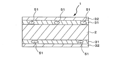
- voids 51 are partially generated in the first coating layer 31 as shown in FIG. 6, and the transmission loss of the optical fiber core 1 may increase.
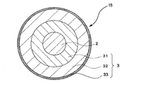
- a second coating layer 32 is coated on the outside of the first coating layer 31, and the optical fiber core wire 1 includes a glass optical fiber 2, a first coating 31, and a second coating layer 32. Yes.
- the work of cleaning the surface and end face of the optical fiber with a solvent is generally performed.
- the jelly on the surface of the optical fiber is removed with a cable having a structure filled with a waterproof jelly or the like, the optical fiber is exposed to a solvent (mainly ethanol) for a long time. For this reason, the optical fiber core wire is required to have solvent resistance.
- the present invention has been made in view of the above, and an optical fiber core having resistance to solvent and micro-bending is unlikely to increase transmission loss even if the optical fiber is submerged and dried. It is to provide.
- One aspect of the present invention is an optical fiber core wire provided with a coating resin provided on the outer periphery of a glass optical fiber and laminated with at least two coating layers, and the most glass of the at least two coating layers
- the Young's modulus of the first coating layer provided on the optical fiber side is PY (MPa)
- the dissolution rate of the coating resin when the optical fiber core wire is immersed in 60 ° C. hot water for 168 hours is E (mass). %), PY ⁇ 0.55 MPa and 1.8 ⁇ E ⁇ 8.61 ⁇ PY + 1.40 are satisfied.
- an optical fiber core that hardly increases transmission loss even when the optical fiber core is immersed and dried, and has solvent resistance and microbend resistance.
- the optical fiber core wire 1 is obtained by coating a glass optical fiber 2 made of quartz glass with at least two layers of a coating resin 3.
- the first coating layer 31 of the coating resin 3 has a Young's modulus PY of 0.55 MPa or less, and the dissolution rate of the coating resin 3 when the optical fiber core wire 1 is immersed in warm water at 60 ° C. for 168 hours.
- E mass%
- the elution rate E of the coating resin satisfies the following formula (1).
- the lower limit of the Young's modulus PY is preferably 0.1 MPa or more, more preferably 0.14 MPa or more from the viewpoint of durability of the first coating layer against external forces such as side pressure and ironing applied during handling.
- E ⁇ 8.61 ⁇ PY + 1.40 in the above formula (1) indicates that the voids of the first coating layer 31 are generated and the first coating layer 31 is not dried when the optical fiber core wire 1 is dried after being submerged. This is derived by examining the relationship between Young's modulus PY and elution rate E. Although details will be described later, the generation of voids is suppressed when the elution rate E satisfies the relationship of E ⁇ 8.61 ⁇ PY + 1.40. Further, excellent solvent resistance (ethanol resistance) is obtained when the relationship of 1.8 ⁇ E in the above formula (1) is satisfied.
- the second coating layer 32 of the coating resin 3 has a Young's modulus of 500 MPa to 1500 MPa. In this way, by setting the Young's modulus of the second coating layer 32 high, sufficient mechanical strength required for the optical fiber core wire 1 is provided.
- an ultraviolet curable resin is mainly used.
- the ultraviolet curable resin includes an oligomer, a dilution monomer, and an additive.
- the additive include a photoinitiator, an antioxidant, a chain transfer agent, a light stabilizer, a plasticizer, a color pigment, a polymerization inhibitor, a sensitizer, and a lubricant.
- the oligomer urethane acrylate resins, epoxy acrylate resins, and polyester acrylate resins are mainly used.
- As the dilution monomer a monofunctional acrylate, a polyfunctional acrylate, or a vinyl monomer such as N-vinylpyrrolidone or N-vinylcaprolactam is used.
- the Young's modulus of the coating resin 3 can be adjusted by the molecular weight of the oligomer and the type of the diluted monomer. That is, as the molecular weight of the oligomer is increased, and the monofunctional monomer is increased as the diluting monomer rather than the polyfunctional monomer, the crosslinking density is lowered and a coating resin having a low Young's modulus is obtained. Therefore, in the first coating layer 31, the crosslinking density is increased by using an oligomer having a number average molecular weight of 500 to 10,000 and increasing the blending amount of a monofunctional monomer as a dilution monomer rather than a polyfunctional monomer.
- the second coating layer 32 has a high Young's modulus of 500 MPa or more and 1500 MPa or less by increasing the crosslinking density by increasing the blending amount of the polyfunctional monomer as the dilution monomer rather than the monofunctional monomer.
- the elution amount of the resin can be adjusted by the blending amount thereof. That is, the amount of resin elution can be increased as the amount of the non-reactive additive is increased.
- the affinity between these non-reactive additives and the molecular structure of the cross-linked part also affects the elution ease during water immersion. That is, since a strong electrostatic attractive force is generated between highly polar functional groups such as hydroxyl groups and esters, a non-reactive additive has a highly polar structure, and a coating layer having a structure in which the cross-linked portion has a low polarity.
- the electrostatic attractive force between the non-reactive additive and the water molecule becomes weak and the amount of elution increases. Conversely, if the polarity of the cross-linked portion is high, the amount of elution is reduced.
- a crosslinking reaction inhibitor such as a chain transfer agent
- the crosslinking density can be lowered, so that the first coating layer 31 can have a low Young's modulus. Ingredients increase. Therefore, considering them, the Young's modulus of each of the first coating layer 31 and the second coating layer 32, and the amount and type of the elution component, depending on the oligomer molecular weight, the type of dilution monomer, the amount of chain transfer agent, etc. Can be adjusted as appropriate.
- the Young's modulus PY of the first coating layer 31 is preferably 0.55 MPa or less, more preferably, a low Young's modulus resin of 0.50 MPa or less is used. The generation of microbend is suppressed, and excellent microbend resistance is obtained.
- the expression of E ⁇ 8.61 ⁇ PY + 1.40 is satisfied, voids are unlikely to be generated in the first coating layer 31 when the optical fiber core wire 1 is immersed and dried.
- the elution component from the coating resin 3 of the optical fiber core wire 1 comes out from the first coating layer 31 having a low crosslinking density. Therefore, the volume reduction amount of the first coating layer 31 increases as the elution rate E increases. In immersion, the first coating layer 31 absorbs water, so there is almost no effect of this volume change. However, the above-mentioned volume reduction caused by this elution component causes a tensile stress in the first coating layer 31 when dried. generate.
- the first coating layer 31 has a lower crosslink density, that is, a lower Young's modulus, so that the tensile strength becomes weaker.
- the solvent resistance (ethanol resistance) is good.
- the appearance change after immersing the optical fiber 1 in ethanol for 1 hour and immersing in hot water at 60 ° C. for 168 hours was 1. It was found that when the content was 8% by mass or more, no coating abnormality such as a crack or a crack occurred in the coating resin 3. This is for the following.
- the ethanol penetrates into the coating resin 3 of the optical fiber core wire 1 and the coating resin 3 swells. When the swelling is significantly increased, the coating resin 3 is destroyed and cracks and tears are generated.
- the optical fiber core wire 1 having a high elution rate E contains a large amount of low-molecular-weight uncrosslinked components in the coating resin 3, and these low-molecular-weight components when immersed in ethanol migrate to the outside of the coating layer. This is because the swelling of the coating resin 3 is thereby suppressed.
- the Young's modulus PY of the first coating layer 31 is constant, voids are more likely to occur as the elution rate E from the coating resin 3 at the time of water immersion is higher.
- the optical fiber core wire 1 having good solvent resistance can be obtained as long as the transmission loss is not easily increased and the range satisfies 1.8 ⁇ E in the formula (1).
- the optical fiber core wire 1 ⁇ / b> B is obtained by coating a glass optical fiber 2 with a coating resin 3 having three layers of a first coating layer 31, a second coating layer 32, and a colored layer 33.
- Each resin is an ultraviolet curable resin.
- the UV curable resin contains an oligomer, a dilution monomer, a photoinitiator, a chain transfer agent, an additive, and the like, but by changing its constituent material, a coating layer having a desired Young's modulus PY and elution rate E is obtained. Can do.
- the elution rate E is the elution rate of the entire coating resin including the colored layer 33.
- the outer diameter of the glass optical fiber 2 is 125 ⁇ m
- the outer diameter of the first coating layer 31 is 195 ⁇ m
- the outer diameter of the second coating layer 32 is 245 ⁇ m
- the outer diameter of the colored layer 33 is 255 ⁇ m.
- an optical fiber ribbon according to an embodiment of the present invention includes four optical fiber cores 1 ⁇ / b> B arranged in parallel in a flat shape, and a coating layer 5 made of an ultraviolet curable resin. It may be configured to cover the optical fiber ribbon 1C. In this case, the elution rate from both the colored resin and the coating resin of the optical fiber core wire can be measured by separating it from the optical fiber tape core wire 1C into a single core.
- the optical fiber core wire 1B is similar to the optical fiber core wire 1 described above in that the first coating layer 31 of the coating resin 3 has a Young's modulus PY Is equal to or less than 0.55 MPa, and the dissolution rate of the coating resin 3 when the optical fiber core wire 1 is immersed in warm water at 60 ° C. for 168 hours is defined as E (mass%), and the above equation (1) is satisfied. Yes.
- the optical fiber cores 1B and 1C like the optical fiber core wire 1, suppress the generation of voids when the elution rate E satisfies the relationship of E ⁇ 8.61 ⁇ PY + 1.40 in the above equation (1). it can. Moreover, when satisfy
- filling the relationship of 1.8 ⁇ E of said Formula (1), it has the outstanding solvent resistance (ethanol resistance). Furthermore, it has excellent microbend resistance when satisfying the relationship of PY ⁇ 0.55.
- the optical fiber core wire 1 having a different Young's modulus of the first coating layer 31 and the elution rate of the coating resin 3 is manufactured, whether voids are generated, solvent resistance, And the anti-microbend resistance properties were investigated.
- a glass optical fiber having an outer diameter (diameter) of about ⁇ 125 ⁇ m is used as the glass optical fiber 2, the first coating layer 31 is formed on the outer periphery, and the second layer is formed on the outer periphery.
- the coating layer 32 was formed, and the optical fiber core wire 1 was manufactured.
- the outer diameter of the first coating layer 31 was 195 ⁇ m, and the outer diameter of the second coating layer 32 was 245 ⁇ m.
- both urethane acrylate-based ultraviolet curable resins are used, and the Young's modulus and coating of each of the first coating layer 31 and the second coating layer 32 are used.
- the elution rate of resin 3 it adjusted suitably with the oligomer molecular weight, the kind of dilution monomer, the compounding quantity of a chain transfer agent, etc.
- the optical fiber core wire 1 having a different Young's modulus PY of the first coating layer 31 and elution rate E of the coating resin 3 is immersed in warm water at 60 ° C. for a predetermined time, taken out, and dried for one day (24 hours). And then observed with a microscope. In the microscopic observation, the case where a void was found in the first coating layer 31 was marked as x, and the case where no abnormality such as a void was found was marked as ⁇ . In this test, the elution rate is changed by changing the water immersion time even for the same optical fiber core.
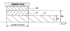
- the Young's modulus PY of the first coating layer 31 was measured by an ISM (In Situ Modulus) test method described in Patent Document 4 and the like. Specifically, as shown in FIG. 4, a sample is prepared by leaving the coating only at one end of 10 mm, and removing the coating from the other part to expose the glass optical fiber 2, and coating the coated resin of the coated part. 3 is fixed with an adhesive or the like. Under a temperature of 23 ° C., a force is gradually applied so as to pull out the glass optical fiber 2 in the end direction where it is not fixed, and the displacement of the glass optical fiber 2 is measured.
- ISM In Situ Modulus
- the force applied to the unfixed end of the glass optical fiber 2 is F
- the displacement of the glass optical fiber 2 is u
- the radius of the glass optical fiber 2 is Rf
- the radius of the first coating layer 31 is Rp
- the coating is left.
- the shear elastic modulus Gp of the first coating layer 31 is calculated using the following equation (2).
- the Young's modulus PY of the first layer 31 is 3 Gp.
- the elution rate E was measured by the following method. 5 m long optical fiber 1 is 23 ° C. and 50% RH (RH is relative humidity, the amount of water vapor contained in the atmosphere at a certain temperature divided by the amount of saturated water vapor at that temperature (unit: %))) For 24 hours and then subtracting the mass of the glass optical fiber 2 from the mass of the optical fiber core 1 to measure the mass (w1) of the coating resin 3 portion. Next, the optical fiber core wire 1 is immersed in warm water heated to 60 ° C. for 168 hours, then taken out from the warm water and dried at 60 ° C. for 24 hours. Thereafter, the mass (w2) of the coating resin 3 portion is measured. From the measured w1 and w2, the elution rate E (mass%) was determined by the following formula (3).
- Optical Fiber Solvent Resistance Test Optical fiber solvent resistance test is performed by immersing a 10 cm long optical fiber core wire 1 in ethanol for 1 hour and then observing the appearance change with a microscope. ⁇ , when a covering abnormality such as a crack or a crack occurred, it was judged as x.
- microbend resistance test of optical fiber As the microbend resistance of optical fiber core wire 1, # 1000 sand paper specified by JIS is attached to the body part of a plastic bobbin (outer diameter: 28 cm). The optical fiber core wire 1 is wound around one layer (about 500 m). Then, within 30 minutes after winding, the transmission loss (L1) is measured at a measurement wavelength of 1550 nm by the cutback method. On the other hand, the transmission loss (L2) is measured at the measurement wavelength of 1550 nm by the same cutback method for the bundle state of the same optical fiber core wire 1 (about 1000 m when not wound around the bobbin).
- the cutback method is a method for obtaining a loss from the difference between the output from the test optical fiber core 1 and the output after the test optical fiber core 1 is cut into a cutback length (for example, 2 m). For this reason, since the loss of the connection point between the test optical fiber core 1 and the test apparatus is subtracted, the accurate loss of the glass optical fiber 2 of the test optical fiber core wire 1 can be measured. Then, L1-L2 is calculated and the value is set as the loss increment. When this value was 0.5 dB / km or less, it was marked with ⁇ , and when it was larger, it was marked with ⁇ . In addition, if the said loss increment is 0.5 dB / km or less, the optical fiber cable using this optical fiber core wire can be used suitably for a communication cable etc.
- Example 1-6 In Example 1 (Sample No. 2), urethane acrylate-based ultraviolet curable resin was used for the first coating layer 31 and the second coating layer 32, and each of the first coating layer 31 and the second coating layer 32 was used.
- the Young's modulus and the elution rate of the coating resin 3 are adjusted by adjusting the oligomer molecular weight, the type of dilution monomer, the blending amount of the chain transfer agent, etc., and the Young's modulus PY of the first coating layer 31 is 0.14 MPa. 3 is adjusted to 2.4 mass% at the elution rate E when immersed in 60 ° C. warm water for 168 hours.
- Example 2 (Sample No. 3), the Young's modulus PY of the first coating layer 31 is 0.20 MPa by adjusting the oligomer molecular weight, the type of dilution monomer, the blending amount of the chain transfer agent, and the like. It is the same as that of the above-mentioned Example 1 except having adjusted the elution rate E at the time of 168-hour warm water 60 degreeC to 1.8 mass%.
- Example 3 sample No.
- the Young's modulus PY of the first coating layer 31 is 0.22 MPa by adjusting the oligomer molecular weight, the type of dilution monomer, the blending amount of the chain transfer agent, and the like. It is the same as that of the above-mentioned Example 1 except having adjusted the elution rate E at the time of 168-hour hot water 60 degreeC adjustment to 2.9 mass%.
- the Young's modulus PY of the first coating layer 31 is 0.33 MPa, the oligomer molecular weight, the type of dilution monomer, the blending amount of the chain transfer agent, etc. are adjusted.
- Example 5 the Young's modulus PY of the first coating layer 31 is 0.49 MPa, the oligomer molecular weight, the type of dilution monomer, the blending amount of the chain transfer agent, etc. are adjusted. It is the same as Example 1 described above except that the elution rate E when immersed in 60 ° C. warm water for 168 hours is adjusted to 4.4 mass%.
- Example 6 Example No.
- the Young's modulus PY of the first coating layer 31 was 0.50 MPa, the oligomer molecular weight, the type of dilution monomer, the blending amount of the chain transfer agent, etc. were adjusted. It is the same as Example 1 described above except that the elution rate E when immersed in 60 ° C. warm water for 168 hours is adjusted to 3.8% by mass.
- Comparative Example 1-3 In Comparative Example 1 (Sample No. 18), the Young's modulus PY of the first coating layer 31 is 0.60 MPa and the coating resin 3 is adjusted by adjusting the oligomer molecular weight, the type of dilution monomer, the blending amount of the chain transfer agent, and the like. It is the same as that of the above-mentioned Example 1 except having adjusted the elution rate E at the time of 168 hour warm water 60 degreeC adjustment to 1.5 mass%. In Comparative Example 2 (Sample No.
- the Young's modulus PY of the first coating layer 31 is 0.81 MPa and the coating resin 3 is adjusted by adjusting the oligomer molecular weight, the type of dilution monomer, the blending amount of the chain transfer agent, and the like. It is the same as that of the above-mentioned Example 1 except having adjusted the elution rate E at the time of 168-hour warm water 60 degreeC to 1.8 mass%.
- the Young's modulus PY of the first coating layer 31 is 0.95 MPa by adjusting the oligomer molecular weight, the type of dilution monomer, the blending amount of the chain transfer agent, and the like. It is the same as that of the above-mentioned Example 1 except having adjusted the elution rate E at the time of 60 degreeC warm water 168 hour immersion to 1.4 mass%.
- FIG. 5 shows the measured values at the measurement points in FIG.
- the measurement points represented by black diamonds are the cases where no voids are generated (the test result is ⁇ )
- the measurement points represented by black rectangles are the cases where the occurrence of voids is observed (test The result is x).
- FIG. 5 shows that voids are more likely to occur as the elution rate E of the coating resin 3 increases and as the Young's modulus PY of the first coating layer 31 decreases.
- the elution rate E of the coating resin 3 is such that no voids are generated if the Young's modulus of the first coating layer 31 is PY and E ⁇ 8.61 ⁇ PY + 1.40 in the above formula (1). found.
- the right side of the above equation (1) was determined as follows. The slope and constant term of the line connecting the point of elution rate 2.4 mass% and Young's modulus 0.14 MPa at the upper limit where no void is generated, and the point of elution rate 5.5 mass% and Young's modulus 0.5 MPa Asked.
- the value of the gradient is 8.61, and the value of the constant term is 1.20.
- the term was sought.
- the value of the gradient is 8.61, and the value of the constant term is 1.59. Taking the middle of these values, the value of gradient was 8.61, the value of the constant term was 1.40, and the above equation of E ⁇ 8.61PY + 1.40 was derived.
- Example 2 The test conditions and results of Examples 1 to 6 and Comparative Examples 1 to 3 are shown in Table 2 below. Further, the results of the solvent resistance test are shown in Table 2 below. From Table 2, after immersing in warm water at 60 ° C. for 168 hours and then drying for 24 hours, if the elution rate E is 1.8% by mass or more as in Examples 1 to 6 and Comparative Example 2, solvent resistance (Test result is ⁇ ).
Landscapes
- Physics & Mathematics (AREA)
- Chemical & Material Sciences (AREA)
- Life Sciences & Earth Sciences (AREA)
- General Physics & Mathematics (AREA)
- Optics & Photonics (AREA)
- Engineering & Computer Science (AREA)
- General Life Sciences & Earth Sciences (AREA)
- Chemical Kinetics & Catalysis (AREA)
- General Chemical & Material Sciences (AREA)
- Geochemistry & Mineralogy (AREA)
- Materials Engineering (AREA)
- Organic Chemistry (AREA)
- Optical Fibers, Optical Fiber Cores, And Optical Fiber Bundles (AREA)
- Surface Treatment Of Glass Fibres Or Filaments (AREA)
Abstract
Priority Applications (4)
| Application Number | Priority Date | Filing Date | Title |
|---|---|---|---|
| CN201280007633.4A CN103380095B (zh) | 2011-02-04 | 2012-02-01 | 光纤芯线 |
| BR112013019929-6A BR112013019929B1 (pt) | 2011-02-04 | 2012-02-01 | fibra óptica e feixe de fibra óptica |
| EP12742592.4A EP2671852A4 (fr) | 2011-02-04 | 2012-02-01 | Fibre optique |
| US13/956,665 US9025924B2 (en) | 2011-02-04 | 2013-08-01 | Optical fiber |
Applications Claiming Priority (2)
| Application Number | Priority Date | Filing Date | Title |
|---|---|---|---|
| JP2011022588A JP5027318B2 (ja) | 2011-02-04 | 2011-02-04 | 光ファイバ心線 |
| JP2011-022588 | 2011-02-04 |
Related Child Applications (1)
| Application Number | Title | Priority Date | Filing Date |
|---|---|---|---|
| US13/956,665 Continuation US9025924B2 (en) | 2011-02-04 | 2013-08-01 | Optical fiber |
Publications (1)
| Publication Number | Publication Date |
|---|---|
| WO2012105246A1 true WO2012105246A1 (fr) | 2012-08-09 |
Family
ID=46602469
Family Applications (1)
| Application Number | Title | Priority Date | Filing Date |
|---|---|---|---|
| PCT/JP2012/000661 Ceased WO2012105246A1 (fr) | 2011-02-04 | 2012-02-01 | Fibre optique |
Country Status (6)
| Country | Link |
|---|---|
| US (1) | US9025924B2 (fr) |
| EP (1) | EP2671852A4 (fr) |
| JP (1) | JP5027318B2 (fr) |
| CN (1) | CN103380095B (fr) |
| BR (1) | BR112013019929B1 (fr) |
| WO (1) | WO2012105246A1 (fr) |
Families Citing this family (9)
| Publication number | Priority date | Publication date | Assignee | Title |
|---|---|---|---|---|
| JP5255690B2 (ja) | 2011-12-27 | 2013-08-07 | 古河電気工業株式会社 | 光ファイバ着色心線、光ファイバテープ心線および光ファイバケーブル |
| JP5465741B2 (ja) | 2012-02-17 | 2014-04-09 | 古河電気工業株式会社 | 光ファイバ心線、光ファイバテープ心線および光ケーブル |
| US9891381B2 (en) | 2013-04-12 | 2018-02-13 | Sumitomo Electric Industries, Ltd. | Coated optical fiber |
| EP2993499B1 (fr) * | 2013-05-02 | 2018-09-05 | Mitsubishi Chemical Corporation | Fibre optique en plastique, procédé de fabrication de celle-ci, capteur, et une bobine pour enrouler une fibre optique en plastique |
| JP6369215B2 (ja) * | 2014-08-13 | 2018-08-08 | 住友電気工業株式会社 | 光ファイバ心線及びその製造方法 |
| KR20170092448A (ko) | 2014-12-03 | 2017-08-11 | 스미토모 덴키 고교 가부시키가이샤 | 광파이버 심선 및 광파이버 테이프 심선 |
| JP2018077303A (ja) * | 2016-11-08 | 2018-05-17 | 住友電気工業株式会社 | 光ファイバ心線 |
| EP3346305A1 (fr) * | 2017-01-06 | 2018-07-11 | Sterlite Technologies Ltd | Fibre optique pour des applications intérieures |
| JP2019045517A (ja) | 2017-08-29 | 2019-03-22 | 住友電気工業株式会社 | 光ファイバ |
Citations (5)
| Publication number | Priority date | Publication date | Assignee | Title |
|---|---|---|---|---|
| JP2003096336A (ja) | 2001-09-27 | 2003-04-03 | Kansai Paint Co Ltd | 被覆用組成物及び被膜 |
| JP2006113103A (ja) | 2004-10-12 | 2006-04-27 | Hitachi Cable Ltd | 着色光ファイバ |
| JP2007334111A (ja) * | 2006-06-16 | 2007-12-27 | Furukawa Electric Co Ltd:The | 光ファイバ、およびそれを用いた光ファイバ心線 |
| JP2007333795A (ja) | 2006-06-12 | 2007-12-27 | Furukawa Electric Co Ltd:The | 光ファイバ心線及びその製造方法 |
| WO2008029488A1 (fr) | 2006-09-08 | 2008-03-13 | The Furukawa Electric Co., Ltd. | Noyau de fibre optique et noyau de fibre optique en ruban |
Family Cites Families (4)
| Publication number | Priority date | Publication date | Assignee | Title |
|---|---|---|---|---|
| JPH01214809A (ja) * | 1988-02-23 | 1989-08-29 | Sumitomo Electric Ind Ltd | 光伝送用フアイバ |
| US5259060A (en) * | 1992-08-11 | 1993-11-02 | Corning Incorporated | Coated optical fibers and method |
| TW542930B (en) * | 2001-03-15 | 2003-07-21 | Sumitomo Electric Industries | Split type optical fiber ribbon core |
| ES2480190T3 (es) * | 2007-11-09 | 2014-07-25 | Draka Comteq B.V. | Fibra óptica resistente a microcurvatura |
-
2011
- 2011-02-04 JP JP2011022588A patent/JP5027318B2/ja active Active
-
2012
- 2012-02-01 WO PCT/JP2012/000661 patent/WO2012105246A1/fr not_active Ceased
- 2012-02-01 CN CN201280007633.4A patent/CN103380095B/zh active Active
- 2012-02-01 EP EP12742592.4A patent/EP2671852A4/fr not_active Withdrawn
- 2012-02-01 BR BR112013019929-6A patent/BR112013019929B1/pt active IP Right Grant
-
2013
- 2013-08-01 US US13/956,665 patent/US9025924B2/en active Active
Patent Citations (5)
| Publication number | Priority date | Publication date | Assignee | Title |
|---|---|---|---|---|
| JP2003096336A (ja) | 2001-09-27 | 2003-04-03 | Kansai Paint Co Ltd | 被覆用組成物及び被膜 |
| JP2006113103A (ja) | 2004-10-12 | 2006-04-27 | Hitachi Cable Ltd | 着色光ファイバ |
| JP2007333795A (ja) | 2006-06-12 | 2007-12-27 | Furukawa Electric Co Ltd:The | 光ファイバ心線及びその製造方法 |
| JP2007334111A (ja) * | 2006-06-16 | 2007-12-27 | Furukawa Electric Co Ltd:The | 光ファイバ、およびそれを用いた光ファイバ心線 |
| WO2008029488A1 (fr) | 2006-09-08 | 2008-03-13 | The Furukawa Electric Co., Ltd. | Noyau de fibre optique et noyau de fibre optique en ruban |
Non-Patent Citations (1)
| Title |
|---|
| See also references of EP2671852A4 * |
Also Published As
| Publication number | Publication date |
|---|---|
| JP2012162415A (ja) | 2012-08-30 |
| US20130315545A1 (en) | 2013-11-28 |
| BR112013019929A2 (pt) | 2017-06-13 |
| EP2671852A4 (fr) | 2018-01-03 |
| JP5027318B2 (ja) | 2012-09-19 |
| EP2671852A1 (fr) | 2013-12-11 |
| CN103380095A (zh) | 2013-10-30 |
| CN103380095B (zh) | 2016-03-02 |
| US9025924B2 (en) | 2015-05-05 |
| BR112013019929B1 (pt) | 2020-12-08 |
Similar Documents
| Publication | Publication Date | Title |
|---|---|---|
| JP5027318B2 (ja) | 光ファイバ心線 | |
| JP5323664B2 (ja) | 光ファイバ心線 | |
| JP5294357B2 (ja) | 光ファイバ着色心線、光ファイバテープ心線及び光ファイバケーブル | |
| TWI666471B (zh) | 光纖帶芯線及光纖纜線 | |
| JP2828733B2 (ja) | 光伝送媒体 | |
| JP4865891B1 (ja) | 光ファイバ素線、光ファイバテープ心線および光ファイバケーブル | |
| EP4185905A1 (fr) | Fibre optique monomode à revêtement mince pour câbles à haute densité et interconnexions | |
| TW201704789A (zh) | 光纖及光纖帶心線 | |
| JPWO2001035143A1 (ja) | 被覆光ファイバ | |
| JP5255690B2 (ja) | 光ファイバ着色心線、光ファイバテープ心線および光ファイバケーブル | |
| WO2012070177A1 (fr) | Coeur de câble à fibres optiques pigmenté | |
| WO2009113667A1 (fr) | Fil de cœur de fibre optique et câble à fibre optique | |
| JP2010217800A (ja) | 光ファイバ | |
| JPWO2008018155A1 (ja) | 光ファイバ | |
| CN112654908B (zh) | 光纤芯线和光纤线缆 | |
| JP3982105B2 (ja) | 被覆光ファイバ | |
| CN118191994A (zh) | 光纤 | |
| CN118444423A (zh) | 光纤 | |
| JP2006113103A (ja) | 着色光ファイバ | |
| JP2001240433A (ja) | 被覆光ファイバ | |
| JP2010210711A (ja) | 光ファイバ心線 | |
| JP7839597B2 (ja) | 高密度ケーブル及び相互接続のための、薄型コーティングを備えたシングルモード光ファイバ | |
| JP2008040369A (ja) | 光ファイバ |
Legal Events
| Date | Code | Title | Description |
|---|---|---|---|
| 121 | Ep: the epo has been informed by wipo that ep was designated in this application |
Ref document number: 12742592 Country of ref document: EP Kind code of ref document: A1 |
|
| WWE | Wipo information: entry into national phase |
Ref document number: 2012742592 Country of ref document: EP |
|
| NENP | Non-entry into the national phase |
Ref country code: DE |
|
| REG | Reference to national code |
Ref country code: BR Ref legal event code: B01A Ref document number: 112013019929 Country of ref document: BR |
|
| ENP | Entry into the national phase |
Ref document number: 112013019929 Country of ref document: BR Kind code of ref document: A2 Effective date: 20130805 |