WO2012105266A1 - Dispositif d'entraînement de moteur - Google Patents
Dispositif d'entraînement de moteur Download PDFInfo
- Publication number
- WO2012105266A1 WO2012105266A1 PCT/JP2012/000711 JP2012000711W WO2012105266A1 WO 2012105266 A1 WO2012105266 A1 WO 2012105266A1 JP 2012000711 W JP2012000711 W JP 2012000711W WO 2012105266 A1 WO2012105266 A1 WO 2012105266A1
- Authority
- WO
- WIPO (PCT)
- Prior art keywords
- circuit
- short
- inverter circuit
- temperature
- state
- Prior art date
- Legal status (The legal status is an assumption and is not a legal conclusion. Google has not performed a legal analysis and makes no representation as to the accuracy of the status listed.)
- Ceased
Links
Images








Classifications
-
- H—ELECTRICITY
- H02—GENERATION; CONVERSION OR DISTRIBUTION OF ELECTRIC POWER
- H02M—APPARATUS FOR CONVERSION BETWEEN AC AND AC, BETWEEN AC AND DC, OR BETWEEN DC AND DC, AND FOR USE WITH MAINS OR SIMILAR POWER SUPPLY SYSTEMS; CONVERSION OF DC OR AC INPUT POWER INTO SURGE OUTPUT POWER; CONTROL OR REGULATION THEREOF
- H02M7/00—Conversion of AC power input into DC power output; Conversion of DC power input into AC power output
- H02M7/66—Conversion of AC power input into DC power output; Conversion of DC power input into AC power output with possibility of reversal
- H02M7/68—Conversion of AC power input into DC power output; Conversion of DC power input into AC power output with possibility of reversal by static converters
- H02M7/72—Conversion of AC power input into DC power output; Conversion of DC power input into AC power output with possibility of reversal by static converters using discharge tubes with control electrode or semiconductor devices with control electrode
- H02M7/79—Conversion of AC power input into DC power output; Conversion of DC power input into AC power output with possibility of reversal by static converters using discharge tubes with control electrode or semiconductor devices with control electrode using devices of a triode or transistor type requiring continuous application of a control signal
- H02M7/797—Conversion of AC power input into DC power output; Conversion of DC power input into AC power output with possibility of reversal by static converters using discharge tubes with control electrode or semiconductor devices with control electrode using devices of a triode or transistor type requiring continuous application of a control signal using semiconductor devices only
-
- H—ELECTRICITY
- H02—GENERATION; CONVERSION OR DISTRIBUTION OF ELECTRIC POWER
- H02P—CONTROL OR REGULATION OF ELECTRIC MOTORS, ELECTRIC GENERATORS OR DYNAMO-ELECTRIC CONVERTERS; CONTROLLING TRANSFORMERS, REACTORS OR CHOKE COILS
- H02P25/00—Arrangements or methods for the control of AC motors characterised by the kind of AC motor or by structural details
- H02P25/16—Arrangements or methods for the control of AC motors characterised by the kind of AC motor or by structural details characterised by the circuit arrangement or by the kind of wiring
- H02P25/22—Multiple windings; Windings for more than three phases
-
- H—ELECTRICITY
- H02—GENERATION; CONVERSION OR DISTRIBUTION OF ELECTRIC POWER
- H02P—CONTROL OR REGULATION OF ELECTRIC MOTORS, ELECTRIC GENERATORS OR DYNAMO-ELECTRIC CONVERTERS; CONTROLLING TRANSFORMERS, REACTORS OR CHOKE COILS
- H02P27/00—Arrangements or methods for the control of AC motors characterised by the kind of supply voltage
- H02P27/04—Arrangements or methods for the control of AC motors characterised by the kind of supply voltage using variable-frequency supply voltage, e.g. inverter or converter supply voltage
- H02P27/06—Arrangements or methods for the control of AC motors characterised by the kind of supply voltage using variable-frequency supply voltage, e.g. inverter or converter supply voltage using DC to AC converters or inverters
-
- H—ELECTRICITY
- H02—GENERATION; CONVERSION OR DISTRIBUTION OF ELECTRIC POWER
- H02M—APPARATUS FOR CONVERSION BETWEEN AC AND AC, BETWEEN AC AND DC, OR BETWEEN DC AND DC, AND FOR USE WITH MAINS OR SIMILAR POWER SUPPLY SYSTEMS; CONVERSION OF DC OR AC INPUT POWER INTO SURGE OUTPUT POWER; CONTROL OR REGULATION THEREOF
- H02M1/00—Details of apparatus for conversion
- H02M1/0067—Converter structures employing plural converter units, other than for parallel operation of the units on a single load
- H02M1/0074—Plural converter units whose inputs are connected in series
-
- H—ELECTRICITY
- H02—GENERATION; CONVERSION OR DISTRIBUTION OF ELECTRIC POWER
- H02M—APPARATUS FOR CONVERSION BETWEEN AC AND AC, BETWEEN AC AND DC, OR BETWEEN DC AND DC, AND FOR USE WITH MAINS OR SIMILAR POWER SUPPLY SYSTEMS; CONVERSION OF DC OR AC INPUT POWER INTO SURGE OUTPUT POWER; CONTROL OR REGULATION THEREOF
- H02M1/00—Details of apparatus for conversion
- H02M1/32—Means for protecting converters other than automatic disconnection
- H02M1/327—Means for protecting converters other than automatic disconnection against abnormal temperatures
Definitions
- the present invention relates to a motor drive device, and more particularly to supply control of drive power to a motor by a plurality of inverters.
- Patent Document 1 discloses a technique for realizing high output of a motor while reducing inverter loss and improving efficiency.
- the motor drive device disclosed in Patent Document 1 switches between using two inverter circuits connected in series and two inverter circuits connected in parallel according to the rotational speed of the motor. Specifically, an inverter circuit connected in series is used when the rotational speed of the motor is lower than a predetermined rotational speed, and an inverter circuit connected in parallel is used when the rotational speed exceeds the predetermined rotational speed.
- each inverter supplies electric power generated from the divided voltage (1/2 of the power supply voltage) to drive the motor. To drive. Thereby, the switching loss in the switching element which comprises an inverter circuit is reduced.
- each of the two inverters connected in parallel supplies the motor with power generated from a power supply voltage that is not divided. Thereby, even if the rotation speed of a motor becomes high and the back electromotive force in the winding of a motor becomes large, it can continue rotating a motor.
- Patent Document 1 when the motor rotates at a predetermined rotation speed or higher, the rotation of the motor is continued by driving the inverter with a high voltage, and the low rotation speed, which is the main operating state of the motor. In some cases, the inverter is driven at a low voltage to reduce the switching loss, thereby realizing higher efficiency and higher output.
- the circuit for switching between the series connection and the parallel connection of the two inverter circuits shown in the prior art is complicated. That is, in order to control the power supply voltage more finely, when trying to expand the circuit shown in the prior art to a configuration in which the series and parallel connections of three or more inverter circuits are switched, the circuit change is not easy and the expandability is improved. Lack.
- the circuit shown in the related art has a circuit that is in an off state and does not operate substantially, that is, a redundant configuration, in each of series connection and parallel connection. This redundancy increases as the number of inverter circuits that divide the power supply voltage increases.
- an object of the present invention is to provide a motor drive device that can achieve high efficiency and high output with a simpler configuration than conventional ones.
- the motor drive device disclosed in the present specification is a motor drive device that receives power supply from a DC power source and drives a motor including independent multiple-system excitation windings, and corresponds to each of the multiple systems.
- the power converter includes a plurality of power converters and a control circuit, and each of the power converters includes an inverter circuit, a cutoff circuit interposed between the corresponding excitation winding and the inverter circuit, and a temperature detector.
- the plurality of inverter circuits are connected in series to the DC power supply, and each inverter circuit supplies power to the excitation winding of the corresponding system when not in a short-circuit state, and the control circuit includes the motor By detecting the operating state of the inverter, setting the inverter circuits related to the number of power converters determined according to the operating state of the motor to a short circuit state, and setting the cutoff circuit to a cutoff state.
- the inverter circuit of the power converter When there is a power converter in which the supply voltage of the DC power supply is supplied to an inverter circuit that is not in a short-circuit state and the temperature detected by the temperature detector exceeds a predetermined temperature, the inverter circuit of the power converter is short-circuited, and While shutting off the shut-off circuit of the power converter, the inverter circuit of another power converter whose detected temperature by the temperature detector does not exceed a predetermined temperature is put into operation, and the shut-off circuit is put into a connected state.
- the motor driving device disclosed in the present specification by a configuration in which a plurality of inverter circuits are connected in series, which is simpler than before, the power supply voltage is divided by the number of inverter circuits according to the operation state of the motor. Electric power can be supplied to the motor.
- the detected temperature of the power converter becomes higher than the predetermined temperature, switching to use another power converter improves the life of the power converter and improves the reliability of the motor drive device. Can do.
- (B) It is a timing chart at the time of switching the phase which short-circuits in order of U phase, V phase, and W phase for every predetermined time.
- (A) It is a figure for demonstrating the DC power supply voltage divided by 3 with the three-phase inverter circuit.
- (B) It is a figure for demonstrating the direct-current power supply voltage when not dividing by a three-phase inverter circuit.
- (b) It is a figure which shows the circuit structure of the interruption
- the motor drive device disclosed in the present specification is a motor drive device that receives power supply from a DC power source and drives a motor including independent multiple-system excitation windings, and corresponds to each of the multiple systems.
- the power converter includes a plurality of power converters and a control circuit, and each of the power converters includes an inverter circuit, a cutoff circuit interposed between the corresponding excitation winding and the inverter circuit, and a temperature detector.
- the plurality of inverter circuits are connected in series to the DC power supply, and each inverter circuit supplies power to the excitation winding of the corresponding system when not in a short-circuit state, and the control circuit includes the motor By detecting the operating state of the inverter, setting the inverter circuits related to the number of power converters determined according to the operating state of the motor to a short circuit state, and setting the cutoff circuit to a cutoff state.
- the inverter circuit of the power converter When there is a power converter in which the supply voltage of the DC power supply is supplied to an inverter circuit that is not in a short-circuit state and the temperature detected by the temperature detector exceeds a predetermined temperature, the inverter circuit of the power converter is short-circuited, and While shutting off the shut-off circuit of the power converter, the inverter circuit of another power converter whose detected temperature by the temperature detector does not exceed a predetermined temperature is put into operation, and the shut-off circuit is put into a connected state.
- each of the plurality of inverter circuits may be formed by a bridge connection of a plurality of switching elements, and the temperature detector may measure the temperature of each switching element.
- the life of the power converter, more specifically, the switching element, and the reliability of the motor driving device can be improved.
- each of the plurality of inverter circuits may include a smoothing capacitor, and the temperature detector may measure the temperature of the smoothing capacitor.
- a smoothing capacitor is likely to be hotter when PWM control is performed than when it is short-circuited in a three-phase inverter circuit. Therefore, according to this configuration, the life of the power converter, more specifically, the smoothing capacitor, and the reliability of the motor drive device can be improved.
- the interruption circuit may include a plurality of switching elements, and the temperature detector may measure the temperature of each of the switching elements.
- each of the plurality of inverter circuits is a three-phase inverter circuit, and the exciting winding is formed by star-shaped windings for three phases, and the temperature detector is provided for each circuit related to each phase.
- the control circuit puts the inverter circuit related to one of the power converters into a short-circuited state, a circuit related to at least one phase whose temperature detected by the temperature detector does not exceed a predetermined temperature is short-circuited It is also possible to make it.
- Each of the plurality of inverter circuits is a three-phase inverter circuit, and a plurality of switching elements are bridge-connected, and the excitation winding is a three-phase winding connected in a star shape,
- the circuit may bring each of the switching elements connected in series related to at least one of the three phases into a conductive state when the three-phase inverter circuit is short-circuited.
- the on-resistance value is reduced, and loss in the apparatus can be reduced.
- it is possible to extend the life of circuits that are not short-circuited so by appropriately determining the number of phases to be short-circuited based on the circuit specifications, etc., the loss of the device can be reduced and the service life can be increased. Can be balanced.
- control circuit does not cause a specific inverter circuit of the plurality of inverter circuits to be in a short-circuited state, and the switching element constituting the inverter circuit that can be short-circuited is more than the switching element constituting the specific inverter circuit. Also, the withstand voltage may be low.
- a three-phase circuit in which a power supply voltage that is not divided is not supplied as compared with a switching element that constitutes a three-phase inverter circuit that is always in a normal operation state and can be supplied with a power supply voltage that is not divided. Since the switching elements constituting the inverter circuit can be configured with a relatively low breakdown voltage, the inverter loss can be reduced as compared with the case where all are configured with a high breakdown voltage.
- control circuit does not cause a specific inverter circuit of the plurality of inverter circuits to be in a short-circuited state, and the switching element constituting the inverter circuit that can be short-circuited is more than the switching element constituting the specific inverter circuit.
- the maximum current capacity may be small.
- the inverter circuit related to the switching element having a large maximum current capacity operates, so that stable driving with suppressed heat generation can be realized.
- the inverter circuit related to the switching element having a small maximum current capacity operates. Therefore, the switching loss can be reduced as compared with the case where the inverter circuit related to the switching element having a large maximum current capacity is used. Can do. Therefore, the efficiency of the motor drive device can be improved and the reliability can be improved.
- the cutoff circuit includes a switching element and includes a voltage detector that measures an on-voltage of the switching element, and the control circuit uses an on-voltage of the switching element to flow an amount of current that flows through the switching element. May be detected.
- the current value can be obtained without using an expensive current sensor that is difficult to operate at high temperature. Therefore, cost reduction and reliability improvement of the motor drive device can be achieved.
- each of the plurality of inverter circuits is a three-phase inverter circuit, and includes a bridge circuit in which a plurality of switching elements are bridge-connected, a smoothing capacitor, a discharge resistor and a discharge switching element connected in series.
- the circuit is connected in parallel,
- the control circuit discharges the charge accumulated in the smoothing capacitor by turning on the discharge switching element for a predetermined time before putting the bridge circuit in a short-circuit state in order to put each inverter circuit in a short-circuit state. It is good to do.
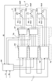
- FIG. 1 is a diagram illustrating an overall configuration of a motor drive device according to a first embodiment of the present invention.
- the motor drive device is composed of an inverter circuit group 2, a cutoff circuit group 3, a control circuit 4, and a position detector 6, and is connected to the DC power supply 1 and the motor 5.
- DC power supply 1 supplies DC power to inverter circuit group 2.
- the inverter circuit group 2 includes three-phase inverter circuits 20a, 20b, and 20c.
- the three-phase inverter circuit 20a is a three-phase bridge inverter circuit in which six switching elements are bridge-connected.
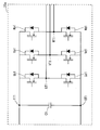
- FIG. 2 is a circuit diagram showing details of the three-phase inverter circuit 20a.
- the switching elements Up1 and Ud1 are connected in series, Vp1 and Vd1 are connected in series, and Wp1 and Wd1 are connected in series. These switching elements connected in series and the smoothing capacitor C1 are connected in parallel.
- the smoothing capacitor C1 smoothes the power supply voltage supplied from the DC power supply 1 and removes noise superimposed on the power supply voltage.
- a connection point UT1 between Up1 and Ud1, a connection point VT1 between Vp1 and Vd1, and a connection point WT1 between Wp1 and Wd1 are connected via switches SU1, SV1, SW1 of a cutoff circuit 30a included in a cutoff circuit group 3 described later.
- the winding is connected to the winding 50aU related to the U phase, the winding 50aV related to the V phase, and the winding 50aW related to the W phase.
- the three-phase inverter circuits 20 a, 20 b, and 20 c have two states, an operating state that receives a DC power supply from the DC power supply 1 and supplies three-phase AC power, and a short-circuited state that is a short-circuited state.
- the operating state and the short circuit state are switched by the control.
- the short circuit state is a state in which both of the switching elements connected in series like the switching elements Up1 and Ud1 of the three-phase inverter circuit 20a are turned on.
- switching elements Up1, Ud1, Vp1, Vd1, Wp1, and Wd1 are turned on (conductive state) when a high level signal is input, and a low level signal is input.
- the three-phase inverter circuits 20b and 20c have the same configuration as the three-phase inverter circuit 20a. A description of the three-phase inverter circuits 20b and 20c is omitted.
- the three-phase inverter circuits 20a, 20b, 20c and the DC power source 1 form a series circuit.
- the contact IT1 in the three-phase inverter circuit 20a is connected to the positive terminal of the DC power supply 1
- the other contact OT1 is connected to the contact IT1 of the three-phase inverter circuit 20b.
- the contact OT1 in the three-phase inverter circuit 20b is connected to the contact IT1 of the three-phase inverter circuit 20c.
- the contact OT1 in the three-phase inverter circuit 20c is connected to the negative terminal of the DC power supply 1.
- the blocking circuit group 3 includes blocking circuits 30a, 30b, and 30c.
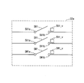
- FIG. 3 is a circuit diagram showing a configuration of the cutoff circuit 30a.
- the blocking circuit 30a includes switches SU1, SV1, and SW1. One end of SU1 is connected to UT1, and the other end is connected to a winding 50aU related to the U phase constituting winding 50a.
- the SU1 performs electrical connection / disconnection between the UT1 and the 50aU by switching on / off of the switch according to the connection instruction / disconnection instruction from the control circuit 4.
- the SV1 has one end connected to the VT1 and the other end connected to the V-phase winding 50aV constituting the winding 50a.
- the switch is switched on / off in accordance with a connection instruction and a cutoff instruction from the control circuit 4. Thus, electrical connection and disconnection of VT1 and 50aV are performed.
- the SW1 has one end connected to the WT1 and the other end connected to the W-phase winding 50aW constituting the winding 50a, and switches the switch on / off in accordance with a connection instruction and a cutoff instruction from the control circuit 4.
- a connection instruction is a high-level signal input
- the cutoff instruction is a low-level signal input.
- the motor 5 includes a plurality of independent excitation windings (windings 50a, 50b, 50c).
- the winding 50a is formed by star connection of a winding 50aU related to the U phase, a winding 50aV related to the V phase, and a winding 50aW related to the W phase.
- One end of each of the windings 50aU, 50aV and 50aW is connected at a neutral point.
- the other end of the winding 50aU is connected to SU1
- the other end of the winding 50aV is connected to SV1
- the other end of the winding 50aW is connected to SW1. Since the windings 50b and 50c have the same configuration as that of the winding 50a, description thereof is omitted.
- a system corresponding to the winding 50a is referred to as a system a
- a system corresponding to the winding 50b is referred to as a system b
- a system corresponding to the winding 50c is referred to as a system c.
- the three-phase inverter and the cutoff circuit constitute a power converter.
- the power converter 70a corresponding to the system a is composed of the three-phase inverter circuit 20a and the cutoff circuit 30a
- the power converter 70b corresponding to the system b is composed of the three-phase inverter circuit 20b and the cutoff circuit 30b.
- the power converter 70c that is configured and corresponds to the system c includes a three-phase inverter circuit 20c and a cutoff circuit 30c.
- the position detector 6 detects the rotational speed N0 as an example of the operation state of the motor 5, and notifies the detected rotational speed N0 to the control circuit 4 as motor rotational speed information.
- the control circuit 4 receives the motor drive command signals Is and Ns.
- Is is a signal indicating whether the motor is rotating forward / reversely / stopping.
- Ns indicates the target rotational speed of the motor.
- Is indicates normal rotation or reverse rotation
- the control circuit 4 performs drive control so that the motor rotates in the rotation direction indicated by Is and the rotation speed indicated by Ns. Further, when Is indicates a stop, the motor is controlled to stop rotating.
- the control circuit 4 detects the rotational speed N0 based on the notification from the position detector 6, switches the operating state and the short-circuit state of the three-phase inverter circuits 20a, 20b, and 20c according to the rotational speed N0, and also cuts off the circuit 30a. , 30b and 30c are switched between a conductive state and a cut-off state.
- control circuit 4 and the position detector 6 are configured separately, the control circuit 4 may be configured to also function as the position detector 6. ⁇ Operation>
- the operation of the motor driving apparatus according to the present embodiment will be described with reference to FIGS. 4 to 6 and FIG. 8, focusing on the control by the control circuit 4.
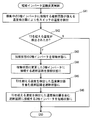
- FIG. 4 is a flowchart showing circuit connection control.
- FIG. 5 is a timing chart relating to a control signal when the three-phase inverter circuit 20a is brought into a conductive state.
- FIG. 6 is a timing chart relating to a control signal when the three-phase inverter circuit 20a is in a short-circuit state.
- FIG. 8 is a diagram for explaining the DC power supply voltage divided by 3 by the three-phase inverter circuit, and FIG. 8B explains the DC power supply voltage when not divided by the three-phase inverter circuit.
- FIG. 8 is a diagram for explaining the DC power supply voltage divided by 3 by the three-phase inverter circuit, and FIG. 8B explains the DC power supply voltage when not divided by the three-phase inverter circuit.
- Up1, Ud1, Vp1, Vd1, Wp1, and Wd1 are signals for controlling the switching elements Up1, Ud1, Vp1, Vd1, Wp1, and Wd1 in the three-phase inverter circuit 20a in FIG. 2, respectively.
- SU1, SV1, and SW1 in FIGS. 5 and 6 correspond to signals for controlling the switches SU1, SV1, and SW1 in the cutoff circuit 30a in FIG. 5 and 6 indicate the high level and low level of the signal. When the signal is at the high level, the switching element and the switch are turned on (conducted), and when the signal is at the low level, the signal is turned off (cut off). Become.
- T0 to T6 in FIGS. 5 and 6 indicate the electrical angle 2 ⁇ .
- the control for Up1, Ud1, Vp1, Vd1, Wp1, and Wd1 in FIG. 5 is usually performed in a three-phase inverter circuit to convert a DC power supply to an AC power supply.
- the state in which this control is performed is the above-described “operating state” in the three-phase inverter circuit.
- Up1, Ud1, Vp1, Vd1, Wp1, and Wd1 are intermittently turned on for ⁇ periods, respectively.
- Up1 and Ud1 are applied with a reverse polarity voltage so that when Up1 is at H level, Ud1 is at L level, Up1 and Ud1, Vp1 and Vd1, and Wp1 and Wd1 are not simultaneously short-circuited.
- a period for turning off is provided (generally referred to as dead time). Also, voltages of opposite polarities are applied to Vp1 and Vd1, and Wp1 and Wd1. Up1, Vp1, and Wp1 are on / off controlled with a phase shift of 2 ⁇ / 3. Further, SU1, SV1, and SW1 in FIG. 5 are all at the H level, and the switches SU1, SV1, and SW1 are all in the on (conducting) state. The state in which this control is performed is the above-described “conducting state” in the cutoff circuit 30a.
- the position detector 6 detects the rotational speed N0 of the motor 5 and notifies the detected rotational speed N0 to the control circuit 4 (S1).
- the detection of the rotation speed N0 is always performed or at predetermined time intervals.
- the control circuit 4 compares the notified rotation speed N0 with a predetermined rotation speed N1 (S2 ).
- the control circuit 4 controls the shut-off circuits 30a, 30b, and 30c so as to be all conductive (S3).
- SU1, SV1, and SW1 of each of the cutoff circuits 30a, 30b, and 30c are controlled according to the timing chart of FIG.
- the control circuit 4 performs control so that each of the three-phase inverter circuits 20a, 20b, and 20c is in an operating state (S4). Specifically, Up1, Ud1, Vp1, Vd1, Wp1, and Wd1 of each of the three-phase inverter circuits 20a, 20b, and 20c are controlled according to the timing chart of FIG. Under the control of S3 and S4, the DC voltage supplied from the DC power source 1 is divided into three by the three-phase inverter circuits 20a, 20b, and 20c. As shown in FIG. 8A, each of the three-phase inverter circuits 20a, 20b, and 20c generates a three-phase AC voltage waveform from the three-divided DC power supply voltage.
- the control circuit 4 sets the cutoff circuit 30a in the cutoff state and sets the cutoff circuits 30b and 30c. Controls to maintain the conduction state (S6). Specifically, the cutoff circuit 30a is controlled based on the timing chart shown in FIG. 6, and the cutoff circuits 30b and 30c are controlled based on the timing chart shown in FIG. Further, the control circuit 4 controls the three-phase inverter circuit 20a to be in a short circuit state, and the three-phase inverter circuits 20b and 20c control to maintain the operating state (S7).
- the control based on the timing chart shown in FIG. 6 is performed for the three-phase inverter circuit 20a
- the control based on the timing chart shown in FIG. 5 is performed for the three-phase inverter circuits 20b and 20c.
- the DC voltage supplied from the DC power source 1 is applied to the three-phase inverter circuits 20b and 20c via the three-phase inverter circuit 20a that is in a short-circuit state. That is, the direct current voltage supplied from the direct current power source 1 changes from a state where it is divided by three by the three-phase inverter circuits 20a, 20b and 20c to a state where it is divided by two by the three-phase inverter circuits 20b and 20c.
- Each of the three-phase inverter circuits 20b and 20c generates a three-phase AC voltage waveform from the DC power supply voltage divided by two. Therefore, the motor 5 can be driven to rotate at a higher speed than in a state where a voltage obtained by dividing the DC power supply by 3 is applied.
- the control circuit 4 controls the cutoff circuits 30a and 30b to be in a cutoff state, and the cutoff circuit 30c is controlled to maintain the conduction state ( S8).
- the cutoff circuits 30a and 30b are controlled based on the timing chart shown in FIG. 6, and the cutoff circuit 30c is controlled based on the timing chart shown in FIG.
- the control circuit 4 controls the three-phase inverter circuits 20a and 20b to be in a short circuit state, and the three-phase inverter circuit 20c controls to maintain the operating state (S9).
- the three-phase inverter circuits 20a and 20b are controlled based on the timing chart shown in FIG.
- the DC voltage supplied from the DC power supply 1 is passed through the three-phase inverter circuits 20a and 20b in the short-circuited state, and the three-phase inverter circuit 20c.
- the DC voltage supplied from the DC power supply 1 changes from the state where it is divided by two by the three-phase inverter circuits 20b and 20c to the state where it is not divided.
- the three-phase inverter circuit 20c generates a three-phase AC voltage waveform from the DC power supply voltage that is not divided. Therefore, the motor 5 can be driven to rotate at a higher speed as compared with a state where a voltage obtained by dividing the DC power supply by 2 is applied.
- a necessary and sufficient DC voltage can be applied to a plurality of three-phase inverter circuits according to the rotation speed of the motor 5. Therefore, it is possible to greatly reduce the switching loss that depends on the magnitude of the DC voltage and occurs during the switching operation. Further, in the motor drive device, the voltage applied to the switching elements constituting the three-phase inverter circuit can be reduced in a region where the number of rotations is frequently used and is relatively small. The reliability of the motor drive device can be improved.
- the three-phase inverter circuits 20a, 20b, and 20c are connected to the windings 50a, 50b, and 50c through the plurality of cutoff circuits 30a, 30b, and 30c, respectively, the three-phase inverter circuits 20a, 20b, and 20c are configured.
- the path (three-phase inverter circuit and winding) that is in an abnormal state can be separated by a cutoff circuit. Therefore, even if an abnormal state due to insulation failure or the like occurs in the motor drive state, the motor drive state can be continued, and an unexpected situation can be avoided.
- the rotational speed N1 is a rotational speed slightly smaller than the rotational speed N1 ′.
- N1 ′ is generated from the DC power supply voltage divided in three in the three-phase inverter circuits 20a, 20b, and 20c by the influence of the counter electromotive force generated in the motor 5 when the rotation speed of the motor 5 exceeds N1 ′.
- the rotation speed is such that the motor 5 cannot be rotated with the AC power supply voltage.
- the rotation speed N2 is a rotation speed slightly smaller than the rotation speed N2 ′.
- N2 ′ is an AC generated from the DC power supply voltage divided by two in the three-phase inverter circuits 20b and 20c due to the influence of the counter electromotive force generated in the motor 5 when the rotation speed of the motor 5 exceeds N2 ′.
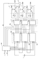
- FIG. 10 is a diagram showing an overall configuration of a motor drive device according to the second embodiment of the present invention.
- the 10 includes the inverter circuit group 2, the power converters 70a to 70c, and the control circuit 4 of the motor drive apparatus illustrated in FIG. 1, and the inverter circuit group 200, the power converters 71a to 71c, and the control circuit 400, respectively. It is the structure replaced with.
- the inverter circuit group 200 includes three-phase inverter circuits 21a, 21b, and 21c.
- FIG. 11 is a diagram showing a circuit configuration of the three-phase inverter circuit 21a.
- the three-phase inverter circuit 21a has a configuration in which temperature detectors Up1_t, Ud1_t, Vp1_t, Vd1_t, Wp1_t, and Wd1_t are added to the three-phase inverter circuit 20a. Since the three-phase inverter circuits 21b and 21c have the same configuration as the three-phase inverter circuit 21a, the following description will focus on the three-phase inverter circuit 21a and the power converter 71a.
- the power converter 71a includes a three-phase inverter circuit 21a and a cutoff circuit 30a.
- the power converter 71b includes a three-phase inverter circuit 21b and a cutoff circuit 30b.
- the power converter 71c includes a three-phase inverter circuit. 21c and a cutoff circuit 30c.
- FIG. 12 is a diagram showing short circuit inverter circuit change control.
- the temperatures of the power converters 71a, 71b, 71c are detected. More specifically, the temperature detectors Up1_t, Ud1_t, Vp1_t, Vd1_t, Wp1_t, and Wd1_t detect the respective temperatures of the switching elements Up1, Ud1, Vp1, Vd1, Wp1, and Wd1, and provide the control circuit 400 with the switching element temperature information. Is fed back (S21). When at least one power converter is in a short-circuit state, the control circuit 400 has a switching element temperature when the three-phase inverter circuit in the at least one power converter is in a short-circuit state.
- the temperature of the switching element is detected as the temperature of the power converter, but this embodiment detects the temperature of the smoothing capacitor as the temperature of the power converter. Yes.
- FIG. 13 is a diagram showing an overall configuration of a motor drive device according to the third embodiment of the present invention.
- 13 includes an inverter circuit group 2, power converters 70a to 70c and a control circuit 4 of the motor drive apparatus shown in FIG. 1, respectively, an inverter circuit group 201, power converters 72a to 72c and a control circuit 401. It is the structure replaced with.
- the inverter circuit group 201 includes three-phase inverter circuits 22a, 22b, and 22c.
- the power converter 72a includes a three-phase inverter circuit 22a and a cutoff circuit 30a.
- the power converter 72b includes a three-phase inverter circuit 22b and a cutoff circuit 30b.
- the power converter 72c includes a three-phase inverter circuit. 22c and a cutoff circuit 30c. Since the configurations of the three-phase inverter circuits 22b and 22c are the same as the configuration of the three-phase inverter circuit 22a, only the three-phase inverter circuit 22a and the power converter 72a will be described below.
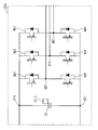
- FIG. 14 is a diagram showing a circuit configuration of the three-phase inverter circuit 22a.
- the three-phase inverter circuit 22a is different from the three-phase inverter circuit 20a in that the smoothing capacitor C1 includes a temperature detector C1_t.
- the temperature detector C1_t detects the temperature of the smoothing capacitor and feeds back the smoothing capacitor temperature information to the control circuit 401.
- the control circuit 401 controls the three-phase inverter circuit of the power converter that is in a short circuit state to be switched to the three-phase inverter circuit of another power converter. This control is to measure the temperature of the smoothing capacitor in place of measuring the temperature of the switching element in S23 to S26 shown in FIG. 12, and is different from the control of FIG. 12 in other points. Absent.
- the smoothing capacitor is likely to have a higher temperature when the PWM control is performed than when the three-phase inverter circuit is short-circuited. Therefore, with this configuration, it is possible to avoid a situation where the temperature of the power converter, more specifically, the smoothing capacitor, becomes too high, to extend the life of the power converter and the smoothing capacitor, and to improve the reliability of the motor drive device. Can do. 4).
- the temperature of the switching element is detected as the temperature of the power converter
- the temperature of the smoothing capacitor is detected as the temperature of the power converter.
- the temperature of the cutoff circuit is detected as the temperature of the power converter.
- FIG. 15 is a diagram showing an overall configuration of a motor drive device according to the fourth embodiment of the present invention.
- the motor drive device shown in FIG. 15 includes the cutoff circuit group 3, the power converters 70a to 70c, and the control circuit 4 of the motor drive device shown in FIG. 1, and the cutoff circuit group 300, the power converters 73a to 73c, and the control circuit 402, respectively. It is the structure replaced with.
- the cutoff circuit group 300 is constituted by cutoff circuits 31a, 31b, and 31c.
- the power converter 73a includes a three-phase inverter circuit 20a and a cutoff circuit 31a.
- the power converter 73b includes a three-phase inverter circuit 20b and a cutoff circuit 31b.
- the power converter 73c includes a three-phase inverter circuit. 20c and a cutoff circuit 31c. Since the cutoff circuits 31b and 31c have the same configuration as the cutoff circuit 31a, only the cutoff circuit 31a and the power converter 73a will be described below.
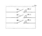
- FIG. 16 is a diagram showing a circuit configuration of the cutoff circuit 31a.
- the interruption circuit 31a is different from the interruption circuit 30a in that it includes temperature detectors SU1_t, SV1_t, and SW1_t.
- the temperature detectors SU1_t, SV1_t, and SW1_t detect the temperatures of the switches SU1, SV1, and SW1, respectively, and feed back to the control circuit 402 as switch temperature information.
- the control circuit 402 controls to switch the three-phase inverter circuit that is in a short-circuit state.
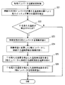
- FIG. 17 is a flowchart showing a short-circuit inverter circuit change control process based on switch temperature information.
- the temperature of each switch is detected by the temperature detector provided in the cutoff circuit connected to the three-phase inverter circuit in the power converter in operation (S41).
- the temperature detector is not limited to the one provided in the cutoff circuit connected to the three-phase inverter circuit in the operating power converter, and the temperature of each switch may be measured by the temperature detector provided in all the cutoff circuits.
- the control circuit 402 determines whether or not a temperature exceeding T3 is detected in the temperature detector (S42). When the three-phase inverter circuit in at least one power converter is in a short-circuit state, the control circuit 402 has a switch whose temperature is higher than a predetermined temperature T3 (S42: Y). The three-phase inverter circuit in the power converter that has been short-circuited is changed to an operating state (S43). And the interruption
- blocking circuit connected to the three-phase inverter circuit in the power converter containing the switch over predetermined temperature T3 is made into an interruption
- FIG. 18 is a diagram showing an overall configuration of a motor drive device according to a fifth embodiment of the present invention.
- the inverter circuit group 202 includes three-phase inverter circuits 23a, 23b, and 23c.
- switching elements that constitute the three-phase inverter circuit 23c have a higher breakdown voltage characteristic than the switching elements that constitute the three-phase inverter circuits 23a and 23b.
- the cutoff circuit group 301 includes cutoff circuits 30a and 30b.
- the power converter 74a includes a three-phase inverter circuit 23a and a cutoff circuit 30a.
- the power converter 74b includes a three-phase inverter circuit 23b and a cutoff circuit 30b.
- the power converter 74c includes a three-phase inverter circuit. 23c.
- the three-phase inverter circuit 23c is not connected to the cutoff circuit, and one end of the windings 50cU, 50cV, 50cW in the winding 50c is directly connected to the UT1, VT1, WT1 of the three-phase inverter circuit 23c.
- the switching elements that constitute the three-phase inverter circuits 23a and 23b are relatively compared with the switching elements that constitute the three-phase inverter circuit 23c that is always in a normal operation state and can be supplied with a power supply voltage that is not divided. Since it can be configured with a low breakdown voltage, the inverter loss can be reduced as compared with the case where all are configured with a high breakdown voltage.
- the conduction loss of the interruption circuit can be reduced. Therefore, high efficiency and low cost of the motor drive device can be achieved.
- FIG. 19 is a diagram showing an overall configuration of a motor drive device according to a sixth embodiment of the present invention.
- the motor drive device shown in FIG. 19 includes the cut-off circuit group 3, the power converters 70a to 70c, and the control circuit 4 of the motor drive device shown in FIG. 1, and the cut-off circuit group 302, the power converters 75a to 75c, and the control circuit 404, respectively. It is the structure replaced with.
- the power converter 75a includes a three-phase inverter circuit 20a and a cutoff circuit 32a
- the power converter 75b includes a three-phase inverter circuit 20b and a cutoff circuit 32b
- the power converter 75c includes a three-phase inverter circuit. 20c and a cutoff circuit 32c.
- the cutoff circuit group 302 is constituted by cutoff circuits 32a, 32b, and 32c. Since the cutoff circuits 32b and 32c have the same configuration as the cutoff circuit 32a, only the cutoff circuit 32a will be described below.
- FIG. 20 is a diagram showing a circuit configuration of the cutoff circuit 32a.
- the cutoff circuit 32a is different from the cutoff circuit 30a in that it includes voltage detectors SU1_v, SV1_v, and SW1_v.
- the voltage detectors SU1_v, SV1_v, and SW1_v detect the voltage values between the terminals of the switches SU1, SV1, and SW1, and feed back to the control circuit 404.
- the control circuit 404 divides the voltage value between the terminals SU1a and SU1b of the switch SU1 by the on-resistance value to obtain the current value of the current flowing through the switch SU1.
- the control circuit 404 also divides the voltage value between the terminals SV1a and SV1b of the switch SV1 by the on-resistance value to obtain the current value of the current flowing through the switch SSV1. Further, the control circuit 404 divides the voltage value between the terminals SW1a and SW1b of the switch SW1 by the on-resistance value to obtain the current value of the current flowing through the switch SW1.
- FIG. 21 is a figure which shows the whole structure of the motor drive device which concerns on the 7th Embodiment of this invention.
- 21 includes the inverter circuit group 2, the power converters 70a to 70c and the control circuit 4 of the motor drive apparatus shown in FIG. 1, and the inverter circuit group 203, the power converters 76a to 76c and the control circuit 405, respectively. It has the structure replaced with.
- the inverter circuit group 203 includes three-phase inverter circuits 24a, 24b, and 24c.
- the power converter 76a is composed of a three-phase inverter circuit 24a and a cutoff circuit 30a
- the power converter 76b is composed of a three-phase inverter circuit 24b and a cutoff circuit 30b
- the power converter 76c is a three-phase inverter circuit. 24c and a cutoff circuit 30c.
- the three-phase inverter circuits 24b and 24c have the same configuration as the three-phase inverter circuit 24a, only the three-phase inverter circuit 24a will be described below.
- FIG. 22 is a diagram showing a circuit configuration of the three-phase inverter circuit 24a.
- the three-phase inverter circuit 24a is different from the three-phase inverter circuit 20a in that it has a discharge resistor R1 and a discharge switching element D1.
- FIG. 23 is a timing chart when the short-circuit operation of the three-phase inverter circuit is performed.
- the control circuit 405 detects the rotational speed of the motor 5 with the position detector 6 and determines whether or not the rotational speed is greater than a predetermined rotational speed. When the rotational speed of the motor is larger than the predetermined rotational speed, a short-circuit command signal (a signal inside the control circuit, not shown) is output so as to short-circuit at least one three-phase inverter circuit. In response to the short-circuit command signal, the control circuit 405 outputs a discharge signal (DS1) shown in FIG. 23 to the three-phase inverter circuit 24a. Upon receiving the discharge signal (DS1), the discharge switching element D1 is turned on for a predetermined time. When the discharging switching element is turned on, the charge of the smoothing capacitor is discharged.
- a short-circuit command signal (a signal inside the control circuit, not shown) is output so as to short-circuit at least one three-phase inverter circuit.
- the control circuit 405 outputs a discharge signal (DS1) shown in FIG. 23 to the three-
- the value of the discharge resistor R1 is set so that the value of the current flowing through the discharge switching element is less than or equal to the maximum current capacity of the discharge switching element.
- FIG. 7A shows a timing chart when only the U phase in the three-phase inverter circuit 20a is short-circuited, and only the switch SU1 related to the U-phase is cut off accordingly.
- the three-phase inverter circuits 20a, 20b, and 20c are in a short-circuit state, it is desirable that two or more phases be short-circuited, and it is most desirable that all three phases be short-circuited. This is because the on-resistance value conducted in a short-circuit state can be reduced, and loss can be reduced.
- FIG. 7B shows a timing chart when the phases to be short-circuited are switched in order of the U phase, the V phase, and the W phase every predetermined time.
- the 3 phase inverter circuit 20a will be in a short circuit state
- one or more circuits related to a phase having a temperature equal to or lower than the predetermined temperature may be short-circuited instead of being short-circuited for a circuit in which the temperature detected for the circuit related to each phase exceeds a predetermined temperature.
- the switching elements constituting the three-phase inverter circuits 20a, 20b, and 20c switching elements having different characteristics may be used. For example, it is desirable to reduce the on-resistance in the order of the three-phase inverter circuits 20a, 20b, and 20c.
- FIGS. 9 (a) and 9 (b) are diagrams showing the circuit configuration of the cutoff circuit according to this modification.
- the cutoff circuit shown in FIG. 9A includes cutoff switch elements SU1a, SV1a, and SW1a.
- the cutoff circuit shown in FIG. 9B includes cutoff switch elements SU1b, SV1b, and SW1b.
- the cutoff switch elements SU1a, SV1a, SW1a, SU1b, SV1b, and SW1b are all constituted by semiconductor switches.
- the cutoff switch elements SU1a, SV1a, SW1a are connected in reverse parallel.
- the cut-off switch elements SU1b, SV1b, SW1b are reversely connected and connected in series.
- the semiconductor switch constituting the cutoff switch may be a unipolar transistor such as a MOSFET or a bipolar transistor such as an IGBT.
- the number of three-phase inverter circuits to be short-circuited is changed according to the rotational speed of the motor.
- the number of three-phase inverter circuits to be short-circuited may be changed according to other operating states of the motor, not limited to the rotational speed of the motor.
- the number of three-phase inverter circuits to be short-circuited may be changed according to the motor torque (motor current).
- the required torque (motor current)
- the DC current from the battery increases.
- the battery can generate heat.
- the three three-phase inverter circuits are put into an operating state and switched to divide the power supply voltage by three. Since three three-phase inverters are connected in series, a large torque can be obtained at a lower current than when the motor is driven by one three-phase inverter.
- the number of three-phase inverter circuits to be activated may be switched according to the current phase of the motor.
- the current phase of the motor may be controlled. Specifically, the current phase is advanced, but by advancing, a reverse magnetic field is applied to the permanent magnets arranged in the rotor constituting the motor. If such control becomes excessive, there is a risk of demagnetization. At this time, by applying a reverse magnetic field to the permanent magnet, the counter electromotive voltage (counter electromotive voltage ⁇ magnetic flux change) generated between the terminals of the motor can be suppressed.
- one temperature detector for one target switching element, smoothing capacitor, or cutoff circuit whose temperature is to be detected.
- one temperature detector may be provided for a plurality of temperature detection targets.
- the switching element and the smoothing capacitor are arranged close to each other, one temperature detector may be arranged at an intermediate position to detect the temperature at that position.
- the above embodiment and the above modifications may be combined.
- the motor drive device of the present invention can achieve high efficiency and high voltage with a simple configuration, it includes a hybrid electric vehicle and an electric vehicle, an electric compressor, an electric power steering, and an elevator that are strongly required to be downsized. It is suitable for all types of motor drive devices and power generation systems such as wind power generation systems.
Landscapes
- Engineering & Computer Science (AREA)
- Power Engineering (AREA)
- Inverter Devices (AREA)
Abstract
Priority Applications (3)
| Application Number | Priority Date | Filing Date | Title |
|---|---|---|---|
| JP2012530798A JP5095042B1 (ja) | 2011-02-03 | 2012-02-02 | モータ駆動装置 |
| CN2012800010322A CN102812631B (zh) | 2011-02-03 | 2012-02-02 | 电动机驱动装置 |
| US13/637,136 US8508180B2 (en) | 2011-02-03 | 2012-02-02 | Motor drive apparatus |
Applications Claiming Priority (2)
| Application Number | Priority Date | Filing Date | Title |
|---|---|---|---|
| JP2011021929 | 2011-02-03 | ||
| JP2011-021929 | 2011-02-03 |
Publications (1)
| Publication Number | Publication Date |
|---|---|
| WO2012105266A1 true WO2012105266A1 (fr) | 2012-08-09 |
Family
ID=46602488
Family Applications (1)
| Application Number | Title | Priority Date | Filing Date |
|---|---|---|---|
| PCT/JP2012/000711 Ceased WO2012105266A1 (fr) | 2011-02-03 | 2012-02-02 | Dispositif d'entraînement de moteur |
Country Status (4)
| Country | Link |
|---|---|
| US (1) | US8508180B2 (fr) |
| JP (1) | JP5095042B1 (fr) |
| CN (1) | CN102812631B (fr) |
| WO (1) | WO2012105266A1 (fr) |
Cited By (6)
| Publication number | Priority date | Publication date | Assignee | Title |
|---|---|---|---|---|
| WO2014196065A1 (fr) * | 2013-06-06 | 2014-12-11 | 株式会社安川電機 | Equipement et système de protection contre les surtensions |
| JP2016077040A (ja) * | 2014-10-03 | 2016-05-12 | セイコーエプソン株式会社 | 回路装置及び電子機器 |
| JPWO2015022718A1 (ja) * | 2013-08-12 | 2017-03-02 | 日本精工株式会社 | モータ制御装置、これを使用した電動パワーステアリング装置および車両 |
| WO2019065882A1 (fr) * | 2017-09-28 | 2019-04-04 | アイシン・エィ・ダブリュ株式会社 | Dispositif de commande d'onduleur |
| WO2022158240A1 (fr) * | 2021-01-22 | 2022-07-28 | 株式会社デンソー | Dispositif de commande pour machine électrique rotative |
| JP2023552359A (ja) * | 2020-12-02 | 2023-12-15 | ヴァレオ、イーオートモーティブ、ジャーマニー、ゲーエムベーハー | インバータ、電気駆動装置、車両、およびインバータの制御可能スイッチを制御するための方法、および対応するコンピュータプログラム製品 |
Families Citing this family (17)
| Publication number | Priority date | Publication date | Assignee | Title |
|---|---|---|---|---|
| FR2987705B1 (fr) * | 2012-03-02 | 2016-11-25 | Alstom Transport Sa | Chaine d'alimentation d'une machine electrique synchrone, systeme de traction electrique comprenant une telle chaine, et procede de commande d'une telle chaine |
| JP5803951B2 (ja) * | 2013-02-08 | 2015-11-04 | 株式会社デンソー | 回転電機駆動システム |
| DE102013218799A1 (de) * | 2013-09-19 | 2015-03-19 | Siemens Aktiengesellschaft | Modularer Stromrichter |
| US20150249419A1 (en) * | 2014-02-28 | 2015-09-03 | Kia Motors Corporation | System and method for controlling inverter |
| JP6415838B2 (ja) * | 2014-03-31 | 2018-10-31 | 住友重機械工業株式会社 | 射出成形機 |
| JP6217667B2 (ja) * | 2015-02-19 | 2017-10-25 | 株式会社豊田自動織機 | 電動圧縮機 |
| EP3131198B1 (fr) * | 2015-08-10 | 2022-06-08 | Goodrich Actuation Systems Limited | Stratégie de commande d'un moteur double voie à aimant permanent à tolérance de pannes pour réduire le couple de traînée sous condition de défaillance |
| CN105048888A (zh) * | 2015-08-18 | 2015-11-11 | 重庆大学 | 一种永磁同步电机绕组切换装置 |
| DE102015216007A1 (de) * | 2015-08-21 | 2017-02-23 | Lenze Drives Gmbh | Antriebssystem |
| CN105245154A (zh) * | 2015-10-26 | 2016-01-13 | 大工科技(上海)有限公司 | 一种驱动系统及其方法 |
| JP6560185B2 (ja) * | 2016-12-06 | 2019-08-14 | ミネベアミツミ株式会社 | モータ駆動制御装置及びモータ駆動制御装置の制御方法 |
| JP7120216B2 (ja) * | 2017-03-31 | 2022-08-17 | 日本電産株式会社 | モータおよび電動パワーステアリング装置 |
| WO2019036496A1 (fr) | 2017-08-15 | 2019-02-21 | Quanten Technologies, Inc. | Système de moteur à barres d'accouplement multiples |
| CN110661431B (zh) * | 2018-06-29 | 2020-12-29 | 北京天诚同创电气有限公司 | 风电变流器及其控制方法、控制装置 |
| DE102018219293A1 (de) | 2018-11-12 | 2020-05-14 | Kaco New Energy Gmbh | Wechselrichter |
| US11063535B2 (en) * | 2019-09-13 | 2021-07-13 | Ford Global Technologies, Llc | Steering motor brake |
| EP4322387A4 (fr) * | 2021-04-07 | 2025-03-26 | Nabtesco Corporation | Dispositif de commande d'onduleur et dispositif de pilotage |
Citations (5)
| Publication number | Priority date | Publication date | Assignee | Title |
|---|---|---|---|---|
| JPS4817557Y1 (fr) * | 1968-05-04 | 1973-05-19 | ||
| JPH10225181A (ja) * | 1997-02-07 | 1998-08-21 | Mitsubishi Electric Corp | 交流電力供給装置および交流電動機 |
| JP2000116149A (ja) * | 1998-10-06 | 2000-04-21 | Meidensha Corp | 高周波電源装置 |
| JP2003333862A (ja) * | 2002-05-15 | 2003-11-21 | Toshiba Corp | 電力変換装置 |
| JP2009278827A (ja) * | 2008-05-16 | 2009-11-26 | Ihi Corp | 駆動装置 |
Family Cites Families (13)
| Publication number | Priority date | Publication date | Assignee | Title |
|---|---|---|---|---|
| JPS4817557U (fr) * | 1971-07-12 | 1973-02-27 | ||
| JPS56139084A (en) * | 1980-03-31 | 1981-10-30 | Toshiba Corp | Control system of ac/dc converter |
| JPH0568301A (ja) * | 1991-09-10 | 1993-03-19 | Toshiba Toransupooto Eng Kk | 車両用補助電源装置 |
| JP3296588B2 (ja) | 1992-05-11 | 2002-07-02 | 株式会社日立製作所 | インバータ装置 |
| JP2000004504A (ja) | 1998-06-15 | 2000-01-07 | Hitachi Ltd | 電気式トルクコンバータの制御方式 |
| JP2000245005A (ja) * | 1999-02-18 | 2000-09-08 | Toshiba Corp | 車両駆動制御装置 |
| JP4559665B2 (ja) | 2001-06-29 | 2010-10-13 | 株式会社東芝 | 電動機駆動制御装置 |
| JP4397244B2 (ja) | 2004-02-10 | 2010-01-13 | トヨタ自動車株式会社 | インバータ装置 |
| JP2006129668A (ja) | 2004-11-01 | 2006-05-18 | Honda Motor Co Ltd | モータ制御装置 |
| US7813847B2 (en) * | 2005-01-25 | 2010-10-12 | Mitsubishi Electric Corporation | Electric car controller |
| JP2009050042A (ja) | 2007-08-13 | 2009-03-05 | Yokohama National Univ | スイッチインバータおよび複数の三相負荷の制御方法 |
| JP4969547B2 (ja) * | 2008-10-14 | 2012-07-04 | トヨタ自動車株式会社 | 制御装置及び充電制御方法 |
| JP2010124570A (ja) * | 2008-11-18 | 2010-06-03 | Toshiba Carrier Corp | 電力変換装置 |
-
2012
- 2012-02-02 US US13/637,136 patent/US8508180B2/en active Active
- 2012-02-02 CN CN2012800010322A patent/CN102812631B/zh active Active
- 2012-02-02 JP JP2012530798A patent/JP5095042B1/ja active Active
- 2012-02-02 WO PCT/JP2012/000711 patent/WO2012105266A1/fr not_active Ceased
Patent Citations (5)
| Publication number | Priority date | Publication date | Assignee | Title |
|---|---|---|---|---|
| JPS4817557Y1 (fr) * | 1968-05-04 | 1973-05-19 | ||
| JPH10225181A (ja) * | 1997-02-07 | 1998-08-21 | Mitsubishi Electric Corp | 交流電力供給装置および交流電動機 |
| JP2000116149A (ja) * | 1998-10-06 | 2000-04-21 | Meidensha Corp | 高周波電源装置 |
| JP2003333862A (ja) * | 2002-05-15 | 2003-11-21 | Toshiba Corp | 電力変換装置 |
| JP2009278827A (ja) * | 2008-05-16 | 2009-11-26 | Ihi Corp | 駆動装置 |
Cited By (15)
| Publication number | Priority date | Publication date | Assignee | Title |
|---|---|---|---|---|
| WO2014196065A1 (fr) * | 2013-06-06 | 2014-12-11 | 株式会社安川電機 | Equipement et système de protection contre les surtensions |
| JPWO2015022718A1 (ja) * | 2013-08-12 | 2017-03-02 | 日本精工株式会社 | モータ制御装置、これを使用した電動パワーステアリング装置および車両 |
| US10093352B2 (en) | 2013-08-12 | 2018-10-09 | Nsk Ltd. | Motor controller, electric power steering device using the motor controller, and vehicle using the motor controller |
| JP2016077040A (ja) * | 2014-10-03 | 2016-05-12 | セイコーエプソン株式会社 | 回路装置及び電子機器 |
| US10236679B2 (en) | 2014-10-03 | 2019-03-19 | Seiko Epson Corporation | Circuit apparatus and electronic appliance |
| JPWO2019065882A1 (ja) * | 2017-09-28 | 2020-04-02 | アイシン・エィ・ダブリュ株式会社 | インバータ制御装置 |
| WO2019065882A1 (fr) * | 2017-09-28 | 2019-04-04 | アイシン・エィ・ダブリュ株式会社 | Dispositif de commande d'onduleur |
| CN111095778A (zh) * | 2017-09-28 | 2020-05-01 | 爱信艾达株式会社 | 逆变器控制装置 |
| US11296617B2 (en) | 2017-09-28 | 2022-04-05 | Aisin Corporation | Inverter control device |
| CN111095778B (zh) * | 2017-09-28 | 2023-12-08 | 株式会社爱信 | 逆变器控制装置 |
| JP2023552359A (ja) * | 2020-12-02 | 2023-12-15 | ヴァレオ、イーオートモーティブ、ジャーマニー、ゲーエムベーハー | インバータ、電気駆動装置、車両、およびインバータの制御可能スイッチを制御するための方法、および対応するコンピュータプログラム製品 |
| US12294326B2 (en) | 2020-12-02 | 2025-05-06 | Valeo Eautomotive Germany Gmbh | Inverter, electric drive, vehicle and method for controlling controllable switches of an inverter and corresponding computer program product |
| WO2022158240A1 (fr) * | 2021-01-22 | 2022-07-28 | 株式会社デンソー | Dispositif de commande pour machine électrique rotative |
| JP2022112718A (ja) * | 2021-01-22 | 2022-08-03 | 株式会社デンソー | 回転電機の制御装置 |
| JP7468377B2 (ja) | 2021-01-22 | 2024-04-16 | 株式会社デンソー | 回転電機の制御装置 |
Also Published As
| Publication number | Publication date |
|---|---|
| US8508180B2 (en) | 2013-08-13 |
| CN102812631A (zh) | 2012-12-05 |
| CN102812631B (zh) | 2013-12-18 |
| JPWO2012105266A1 (ja) | 2014-07-03 |
| US20130026968A1 (en) | 2013-01-31 |
| JP5095042B1 (ja) | 2012-12-12 |
Similar Documents
| Publication | Publication Date | Title |
|---|---|---|
| JP5095042B1 (ja) | モータ駆動装置 | |
| JP6169203B1 (ja) | 電動機制御装置および電動機制御方法 | |
| JP5436592B2 (ja) | モータ制御装置、モータ制御装置に適用される電流制御方法、およびモータ制御装置を用いた電動パワーステアリング装置 | |
| JP5622053B2 (ja) | 多相回転機の制御装置、および、これを用いた電動パワーステアリング装置 | |
| CN102570936B (zh) | 旋转机的控制装置、旋转机系统、车辆、电动汽车及发电系统 | |
| JP4752772B2 (ja) | 交流電動機の巻線切替装置及びその巻線切替システム | |
| JP6150757B2 (ja) | 負荷駆動装置 | |
| JP5967299B2 (ja) | 電力変換装置及びその制御方法 | |
| JP2009303298A (ja) | 交流モータ装置 | |
| JP6494860B2 (ja) | 電動パワーステアリング装置用の3相2重化モータ装置 | |
| JP2015139341A (ja) | 電力変換装置 | |
| JP6426465B2 (ja) | 電力変換装置 | |
| JP6416414B2 (ja) | 交流回転機の制御装置 | |
| JP6423264B2 (ja) | 電力変換装置 | |
| JP6305495B1 (ja) | インバータ制御装置及びインバータ制御方法 | |
| JP2016019385A (ja) | モータ装置 | |
| US20210221428A1 (en) | Control for electric power steering | |
| JPWO2014024460A1 (ja) | モータ制御装置 | |
| WO2017130668A1 (fr) | Dispositif de conversion de puissance | |
| JP2010130845A (ja) | インバータの放電装置 | |
| JP6669532B2 (ja) | 電力変換装置 | |
| WO2020116226A1 (fr) | Dispositif de conversion de puissance | |
| WO2014112232A1 (fr) | Dispositif de conversion de puissance électrique | |
| JP2015122883A (ja) | モータ駆動装置 | |
| JP2008011670A (ja) | インバータ装置 |
Legal Events
| Date | Code | Title | Description |
|---|---|---|---|
| WWE | Wipo information: entry into national phase |
Ref document number: 201280001032.2 Country of ref document: CN |
|
| WWE | Wipo information: entry into national phase |
Ref document number: 2012530798 Country of ref document: JP |
|
| WWE | Wipo information: entry into national phase |
Ref document number: 13637136 Country of ref document: US |
|
| 121 | Ep: the epo has been informed by wipo that ep was designated in this application |
Ref document number: 12742073 Country of ref document: EP Kind code of ref document: A1 |
|
| NENP | Non-entry into the national phase |
Ref country code: DE |
|
| 122 | Ep: pct application non-entry in european phase |
Ref document number: 12742073 Country of ref document: EP Kind code of ref document: A1 |