WO2012105414A1 - Surchauffeur de gaz et corps de raccordement de surchauffeur - Google Patents
Surchauffeur de gaz et corps de raccordement de surchauffeur Download PDFInfo
- Publication number
- WO2012105414A1 WO2012105414A1 PCT/JP2012/051697 JP2012051697W WO2012105414A1 WO 2012105414 A1 WO2012105414 A1 WO 2012105414A1 JP 2012051697 W JP2012051697 W JP 2012051697W WO 2012105414 A1 WO2012105414 A1 WO 2012105414A1
- Authority
- WO
- WIPO (PCT)
- Prior art keywords
- gas
- superheater
- outer tube
- tube
- heat generating
- Prior art date
- Legal status (The legal status is an assumption and is not a legal conclusion. Google has not performed a legal analysis and makes no representation as to the accuracy of the status listed.)
- Ceased
Links
Images


Classifications
-
- H—ELECTRICITY
- H05—ELECTRIC TECHNIQUES NOT OTHERWISE PROVIDED FOR
- H05B—ELECTRIC HEATING; ELECTRIC LIGHT SOURCES NOT OTHERWISE PROVIDED FOR; CIRCUIT ARRANGEMENTS FOR ELECTRIC LIGHT SOURCES, IN GENERAL
- H05B3/00—Ohmic-resistance heating
- H05B3/40—Heating elements having the shape of rods or tubes
- H05B3/42—Heating elements having the shape of rods or tubes non-flexible
- H05B3/44—Heating elements having the shape of rods or tubes non-flexible heating conductor arranged within rods or tubes of insulating material
-
- C—CHEMISTRY; METALLURGY
- C01—INORGANIC CHEMISTRY
- C01B—NON-METALLIC ELEMENTS; COMPOUNDS THEREOF; METALLOIDS OR COMPOUNDS THEREOF NOT COVERED BY SUBCLASS C01C
- C01B33/00—Silicon; Compounds thereof
- C01B33/02—Silicon
- C01B33/021—Preparation
- C01B33/027—Preparation by decomposition or reduction of gaseous or vaporised silicon compounds other than silica or silica-containing material
- C01B33/033—Preparation by decomposition or reduction of gaseous or vaporised silicon compounds other than silica or silica-containing material by reduction of silicon halides or halosilanes with a metal or a metallic alloy as the only reducing agents
-
- F—MECHANICAL ENGINEERING; LIGHTING; HEATING; WEAPONS; BLASTING
- F27—FURNACES; KILNS; OVENS; RETORTS
- F27D—DETAILS OR ACCESSORIES OF FURNACES, KILNS, OVENS OR RETORTS, IN SO FAR AS THEY ARE OF KINDS OCCURRING IN MORE THAN ONE KIND OF FURNACE
- F27D99/00—Subject matter not provided for in other groups of this subclass
- F27D99/0001—Heating elements or systems
- F27D99/0006—Electric heating elements or system
-
- H—ELECTRICITY
- H05—ELECTRIC TECHNIQUES NOT OTHERWISE PROVIDED FOR
- H05B—ELECTRIC HEATING; ELECTRIC LIGHT SOURCES NOT OTHERWISE PROVIDED FOR; CIRCUIT ARRANGEMENTS FOR ELECTRIC LIGHT SOURCES, IN GENERAL
- H05B2203/00—Aspects relating to Ohmic resistive heating covered by group H05B3/00
- H05B2203/022—Heaters specially adapted for heating gaseous material
Definitions
- the present invention relates to, for example, a gas superheater used for heating a heated gas introduced into an electric furnace to a high temperature and a superheater assembly.
- a zinc reduction method for producing high-purity polycrystalline silicon by reducing silicon tetrachloride with metallic zinc has attracted attention as a method for producing polycrystalline silicon as a raw material for silicon solar cells.
- silicon tetrachloride and zinc as raw materials are vaporized at 900 to 1,100 ° C. and heated to cause a gas phase reduction reaction.
- silicon tetrachloride Since silicon tetrachloride has a boiling point of 58 ° C, it can be vaporized relatively easily. However, it reacts violently with water and is corrosive. Care should be taken in handling such as selection.
- Patent Document 1 discloses a gas heater that obtains a high-temperature gas by heating a metal resistor to a high temperature by direct energization, and bringing the gas directly into contact with the metal resistor that has reached a high temperature.
- Patent Document 2 a heating element including a heat generating part formed in a spiral shape and an electrode terminal taken out from the heat generating part in a protective tube disposed through the inner wall of the furnace, A gas heating device is disclosed that is inserted so as to be located inside the furnace. In this gas heating apparatus, gas or air is guided to a heat generating portion formed in a spiral shape and heated, and the heated gas or air is discharged into the furnace.
- this gas heating device has a structure in which the heat generating part penetrates the furnace inner wall, the maximum length of the heat generating part is limited by the thickness of the furnace inner wall, and as a result, sufficient control of the heating temperature is achieved. There is a problem that it is difficult.
- the present invention has been made in order to solve the conventional problems in a gas superheater for heating a gas supplied to a reactor or the like to a high temperature, and its purpose is to provide a corrosive and reactive gas. It is an object of the present invention to provide a gas superheater and a superheater assembly that can be heated under close control to a target temperature of 900 to 1,100 ° C.
- an object of the present invention is to provide a gas superheater and a superheater assembly.
- a gas superheater comprises: A gas superheater for heating a gas to a high temperature, The gas superheater, An outer tube having a gas inlet and a gas outlet; A plurality of heat generating tubes disposed in the longitudinal direction of the outer tube, and containing a heat generating element therein; It is characterized by comprising at least.
- a side plate in which a hole for inserting the heat generating tube is formed in advance is disposed at both ends of the outer tube, and the heat generating tube is inserted into the hole.
- the heating tube is formed longer than the entire length of the outer tube, A heating tube having a length longer than that of the outer tube may be extended from one end of the outer tube to the other end. Alternatively, the heating tube is less than half the length of the outer tube, The exothermic tube having a length of half or less may be inserted from both ends of the outer tube to the vicinity of the center of the outer tube.
- an external heating means is disposed on the outer periphery of the outer tube.
- the heating element is preferably a resistance heating element made of metal or ceramic.
- a substantially semicircular rectifying plate is disposed on the inner wall of the outer tube at a predetermined interval, and the rectifying plates adjacent to each other are arranged on one side of the inner wall of the outer tube. It is preferable that they are alternately arranged on the side and the other side.
- the heated gas flowing inside collides with the rectifying plate and the flow path is changed, so that a long flow path for the gas in the outer tube can be secured, and the entire gas is uniformly heated. be able to.
- the material of the outer tube and the heating tube is quartz.
- the heated gas is preferably silicon tetrachloride.
- the superheater coupling body of the present invention is configured by connecting a plurality of the above gas superheaters.
- the gas supplied to the reactor or the like can be heated while strictly controlling to the target temperature. Further, even when a corrosive gas is heated, a heating element such as a coil is not corroded by the gas.
- the length of the heat generating part can be set freely, the control of the heating temperature is easy.
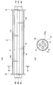
- FIG. 1 is an exploded perspective view showing a main part of a gas superheater according to an embodiment of the present invention.
- 2A is a schematic cross-sectional view in a state where the gas superheater of FIG. 1 is assembled
- FIG. 2B is a cross-sectional view in the direction of the line BB in FIG. 2A.
- FIG. 3 is a perspective view showing another aspect of the side plate shown in FIG.
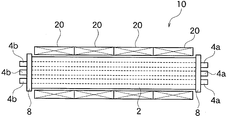
- FIG. 4 is a schematic front view of a gas superheater according to another embodiment of the present invention.
- FIG. 5 is a schematic cross-sectional view of a gas superheater according to still another embodiment of the present invention.
- FIG. 6 is a schematic cross-sectional view of a gas superheater according to still another embodiment of the present invention.
- FIG. 1 is an exploded perspective view of a gas superheater according to an embodiment of the present invention
- FIG. 2A is a schematic cross-sectional view of the assembled gas superheater of FIG.
- FIG. 2B is a schematic cross-sectional view in the direction of line BB in FIG.
- the gas to be heated is silicon tetrachloride used for producing high-purity polycrystalline silicon.
- the gas superheater 10 of the present embodiment includes a substantially cylindrical outer tube 2, a plurality of (four in this embodiment) heat generating tubes 4 disposed at both ends projecting from the outer tube 2, It has a plurality of heating elements 6 housed inside the heating tube 4. Further, both end portions of the outer tube 2 are sealed by the side plates 8 and 8 after the heating tube 4 is accommodated.
- a gas inlet 2a and a gas outlet 2b are formed at both ends of the outer tube 2, respectively.
- one side plate 8 may be disposed at each end of the outer tube 2, but in order to maintain strength, an inner closing plate 8a and an outer closing plate 8b, as in the side plate 8 'shown in FIG. It is also possible to adopt a structure in which a heat insulating material such as a ceramic fiber blanket is loaded between them.
- Quartz, silicon carbide, silicon nitride or the like having corrosion resistance and heat resistance can be used as the material of the outer tube 2, the heat generating tube 4, and the side plate 8 (8 '). Quartz is suitable when the gas to be handled is silicon tetrachloride as in this embodiment.
- the number of heating tubes 4 and heating elements 6 housed in the outer tube 2 is usually 2 to 10, but this number is not particularly limited and is appropriately determined according to the required heat capacity.
- the respective heat generating tubes 4 are arranged substantially equally apart.
- the exothermic tube 4 has a length in which both end portions 4a and 4b project to the outside through both side plates 8 and 8, and the heating element 6 extends from either one of the projecting end portions 4a and 4b. Is inserted into the heat generating tube 4 and accommodated.
- the heating element 6 can be a resistance heater such as Kanthal alloy, nickel-chromium alloy, or silicon carbide.
- a resistance heater such as Kanthal alloy, nickel-chromium alloy, or silicon carbide.
- As the shape of the heater a coil shape, a rod shape, a spiral shape, a cylindrical shape, or the like can be used as appropriate.
- the outer tube 2 containing the heat generating tube 4 is usually installed horizontally, but can also be installed vertically or obliquely depending on the installation space.
- the heat generating tube 4 longer than the outer tube 2 is accommodated in the outer tube 2, but instead of this, two divided bodies can be arranged linearly. That is, when the length of the heating element 6 or the heating tube 4 is limited, as shown in FIG. 5, two bottomed cylindrical heating tubes 14 with one end sealed in advance are prepared as a set. The end portions 14a on the closed side of the heat generating tubes 14 and 14 are inserted into the outer tube 2 from both sides in a substantially straight line, and the end portions 14b on the open side are inserted into the side plates 8 and 8 of the outer tube 2. It is also possible to have a structure protruding from the outside. In FIG.
- the end portions 14 a and 14 a on the closed side of the pair of heat generating tubes 14 and 14 are arranged adjacent to each other at a predetermined interval in the central portion of the outer tube 2.
- the distance between the end portions 14a of the heat generating tubes 14 adjacent to each other is not particularly limited, but it is preferable to secure about 1 to 10 cm.
- a plurality (four in the embodiment) of rectifying plates 16 are provided on the inner wall of the outer tube 2 with respect to the axial direction of the outer tube 2. Are arranged in a vertical direction. These rectifying plates 16 have a substantially semicircular shape, and in a cross-sectional view of the outer tube 2 provided with the rectifying plate 16, a space on the opposite side to the side where the rectifying plate 16 is provided is a substantially semicircular notch. Part 16a is formed. The cutout portion 16 a may be arcuate and the shape is determined by the shape of the rectifying plate 16.
- the heat generating tube 4 has a structure penetrating each rectifying plate 16, and the heat generating tube 4 and the rectifying plate 16 in the penetrating portion are integrated by fixing several points by welding.
- the gas passes through the inside of the outer tube 2 through the notch 16a. It is preferable that the notch positions of the rectifying plates 16 adjacent to each other are alternated by 180 degrees. As a result, the gas passing therethrough changes the flow path while hitting the rectifying plate 16, and the passage distance in the outer tube 2 is ensured to be long, whereby heat exchange can be performed efficiently.
- the distance between the rectifying plates adjacent to each other is preferably 10 to 30 cm.
- Quartz, silicon carbide, silicon nitride, or the like can be used as the material of the rectifying plate 16. Quartz is preferred when the gas to be handled is silicon tetrachloride.
- the outer periphery of the outer tube 2 may be covered with a heat insulating material, in order to reduce heat dissipation loss and increase thermal efficiency, for example, as in the other embodiment shown in FIG.
- the external heating means 20 is disposed in each of the defined areas and heated from the outside to the inside.
- the heating capacity of the internal heating tube 4 can be set to be small accordingly, so that the heat exchanger can be made more compact than before.
- a resistance heater such as a cantal alloy, a nickel chromium alloy, or silicon carbide can be used.
- each region of the external heating means 20 is preferably larger on the gas inlet 2a side shown in FIG. 1 than on the gas outlet 2b side.
- silicon tetrachloride gas to be heated is introduced into the outer tube 2 from the gas inlet 2a, and if the heating element 6 generates heat to a high temperature when energized, the heated gas is The temperature gradually increases and the air flows into the downstream side of the outer tube 2 while colliding with the rectifying plate 16, and finally reaches a temperature of 900 to 1,100 ° C. and is ejected to the outside from the gas outlet 2b.
- silicon tetrachloride gas heated to a predetermined temperature can be supplied into the furnace.
- the length of the heat generating part is not limited by the thickness of the furnace inner wall, and can be designed to a free length.
- the gas superheater 10 according to one embodiment of the present invention has been described above, but the present invention is not limited to the above embodiment.
- two or three or more gas superheaters 10 described above can be connected as shown in FIG.
- the superheater connector 30 for example, corrosive and reactive gas can be heated under strictly control to a target temperature of 900 to 1,100 ° C.
- the raw material silicon tetrachloride gas can be heated to a target temperature of 900 to 1,100 ° C. with strict control and supplied to the reduction reactor. is there.
- the gas superheater 10 is not limited to heating silicon tetrachloride gas, and can be used as a superheater for various gases.
- an external heater (external heating means 20) composed of upper and lower divided four units was installed on the outer periphery of the outer tube 2.
- the capacity of the external heater was set to 20.5 kW in the two zones on the gas inlet side and 10 kW in the two zones on the gas outlet side.
- the respective heaters of the gas superheater configured as described above were energized, and silicon tetrachloride gas heated to 80 ° C. was introduced from the gas inlet 2a side at a flow rate of 600 kg / hr.
- the temperature on the gas outlet 2b side of the silicon tetrachloride gas was measured and found to be 970 ° C.
- the gas superheater 10 of the present invention can obtain a high-temperature gas under a strict temperature control with a compact configuration.
Landscapes
- Engineering & Computer Science (AREA)
- Chemical & Material Sciences (AREA)
- Organic Chemistry (AREA)
- Mechanical Engineering (AREA)
- General Engineering & Computer Science (AREA)
- Inorganic Chemistry (AREA)
- Furnace Details (AREA)
- Physical Or Chemical Processes And Apparatus (AREA)
- Silicon Compounds (AREA)
Abstract
L'invention vise à proposer un surchauffeur de gaz et un corps de raccordement de surchauffeur de gaz, avec lesquels un gaz corrosif et réactif, et en particulier du tétrachlorure de silicium gazeux en tant que matière première, dans un procédé de réduction du zinc qui fabrique du silicium de haute pureté, peut être strictement contrôlé et chauffé à une température cible de 900-1100°C.
A cet effet, est proposé un surchauffeur de gaz caractérisé en ce que de multiples tubes de génération de chaleur, qui reçoivent des corps générant de la chaleur, sont disposés dans la direction longitudinale à l'intérieur d'un tube cylindrique externe équipé d'un orifice d'entrée de gaz et d'un orifice de sortie de gaz.
Priority Applications (1)
| Application Number | Priority Date | Filing Date | Title |
|---|---|---|---|
| JP2012555827A JPWO2012105414A1 (ja) | 2011-02-03 | 2012-01-26 | ガス過熱器および過熱器連結体 |
Applications Claiming Priority (2)
| Application Number | Priority Date | Filing Date | Title |
|---|---|---|---|
| JP2011021576 | 2011-02-03 | ||
| JP2011-021576 | 2011-02-03 |
Publications (1)
| Publication Number | Publication Date |
|---|---|
| WO2012105414A1 true WO2012105414A1 (fr) | 2012-08-09 |
Family
ID=46602631
Family Applications (1)
| Application Number | Title | Priority Date | Filing Date |
|---|---|---|---|
| PCT/JP2012/051697 Ceased WO2012105414A1 (fr) | 2011-02-03 | 2012-01-26 | Surchauffeur de gaz et corps de raccordement de surchauffeur |
Country Status (3)
| Country | Link |
|---|---|
| JP (1) | JPWO2012105414A1 (fr) |
| TW (1) | TW201234912A (fr) |
| WO (1) | WO2012105414A1 (fr) |
Cited By (3)
| Publication number | Priority date | Publication date | Assignee | Title |
|---|---|---|---|---|
| CN106556137A (zh) * | 2016-10-31 | 2017-04-05 | 江阴市国豪电热电器制造有限公司 | 一种加热均匀的气体电加热器 |
| JP2021089227A (ja) * | 2019-12-05 | 2021-06-10 | 株式会社島津製作所 | イオン分析装置 |
| JP2022177349A (ja) * | 2021-05-18 | 2022-12-01 | 日本特殊陶業株式会社 | 液体加熱装置 |
Citations (7)
| Publication number | Priority date | Publication date | Assignee | Title |
|---|---|---|---|---|
| JPH0338980U (fr) * | 1989-08-23 | 1991-04-15 | ||
| JPH05254810A (ja) * | 1992-03-06 | 1993-10-05 | Asahi Chem Ind Co Ltd | 窒化アルミニウム粉末の連続製造法 |
| JPH0621242U (ja) * | 1992-08-11 | 1994-03-18 | 株式会社金門製作所 | 超純水加温装置 |
| JPH0623242U (ja) * | 1992-08-21 | 1994-03-25 | 東京ハイテック株式会社 | 流体加熱器 |
| JPH0835724A (ja) * | 1994-07-21 | 1996-02-06 | Ushio Inc | 気体加熱装置 |
| JP2002083672A (ja) * | 1999-09-30 | 2002-03-22 | Miyoshi Electronics Corp | パイプヒータおよびパイプヒータを用いる流体加熱装置 |
| JP2008082655A (ja) * | 2006-09-28 | 2008-04-10 | Covalent Materials Corp | 液体加熱装置 |
-
2012
- 2012-01-26 WO PCT/JP2012/051697 patent/WO2012105414A1/fr not_active Ceased
- 2012-01-26 JP JP2012555827A patent/JPWO2012105414A1/ja active Pending
- 2012-02-02 TW TW101103392A patent/TW201234912A/zh unknown
Patent Citations (7)
| Publication number | Priority date | Publication date | Assignee | Title |
|---|---|---|---|---|
| JPH0338980U (fr) * | 1989-08-23 | 1991-04-15 | ||
| JPH05254810A (ja) * | 1992-03-06 | 1993-10-05 | Asahi Chem Ind Co Ltd | 窒化アルミニウム粉末の連続製造法 |
| JPH0621242U (ja) * | 1992-08-11 | 1994-03-18 | 株式会社金門製作所 | 超純水加温装置 |
| JPH0623242U (ja) * | 1992-08-21 | 1994-03-25 | 東京ハイテック株式会社 | 流体加熱器 |
| JPH0835724A (ja) * | 1994-07-21 | 1996-02-06 | Ushio Inc | 気体加熱装置 |
| JP2002083672A (ja) * | 1999-09-30 | 2002-03-22 | Miyoshi Electronics Corp | パイプヒータおよびパイプヒータを用いる流体加熱装置 |
| JP2008082655A (ja) * | 2006-09-28 | 2008-04-10 | Covalent Materials Corp | 液体加熱装置 |
Cited By (5)
| Publication number | Priority date | Publication date | Assignee | Title |
|---|---|---|---|---|
| CN106556137A (zh) * | 2016-10-31 | 2017-04-05 | 江阴市国豪电热电器制造有限公司 | 一种加热均匀的气体电加热器 |
| JP2021089227A (ja) * | 2019-12-05 | 2021-06-10 | 株式会社島津製作所 | イオン分析装置 |
| JP7327130B2 (ja) | 2019-12-05 | 2023-08-16 | 株式会社島津製作所 | イオン分析装置 |
| JP2022177349A (ja) * | 2021-05-18 | 2022-12-01 | 日本特殊陶業株式会社 | 液体加熱装置 |
| JP7594492B2 (ja) | 2021-05-18 | 2024-12-04 | 日本特殊陶業株式会社 | 液体加熱装置 |
Also Published As
| Publication number | Publication date |
|---|---|
| JPWO2012105414A1 (ja) | 2014-07-03 |
| TW201234912A (en) | 2012-08-16 |
Similar Documents
| Publication | Publication Date | Title |
|---|---|---|
| EP2766685B1 (fr) | Échangeur de chaleur hybride à tubes de gaz-eau combinés | |
| WO2013141728A2 (fr) | Échangeur de chaleur à double usage | |
| EP3676539B1 (fr) | Échangeur de chaleur pour chaudière, et tube d'échangeur de chaleur | |
| KR101084162B1 (ko) | 히터모듈 조립체 | |
| CN102893098A (zh) | 换热器 | |
| KR20150028468A (ko) | 전기 순간온수기용 가열장치 | |
| WO2012105414A1 (fr) | Surchauffeur de gaz et corps de raccordement de surchauffeur | |
| CN103026143B (zh) | 换热器 | |
| JP5288169B2 (ja) | 熱交換器および温水装置 | |
| JP2008281287A (ja) | 電気式連続湯沸器 | |
| KR20100023730A (ko) | 난방수 및 온수 겸용 전기 보일러 | |
| CN108072164A (zh) | 燃气与电加热壁挂炉 | |
| US10024572B1 (en) | Heat exchanger | |
| JP4904374B2 (ja) | マイクロリアクタ | |
| KR101083633B1 (ko) | 열처리수의 믹스를 이용한 열증폭기 | |
| KR101809169B1 (ko) | 유체 가열 장치 | |
| KR20090129147A (ko) | 탄소 섬유를 이용한 발열체의 구조 및 이를 적용한 보일러 | |
| CN210772735U (zh) | 电磁加热器 | |
| CN217978750U (zh) | 蒸汽发生器 | |
| ES2340757B1 (es) | Calentador instantaneo de agua por induccion electromagnetica. | |
| KR100698405B1 (ko) | 나선 구조형 가열유닛과 이를 이용한 히팅장치 | |
| JP7364456B2 (ja) | 加熱装置 | |
| JPS58108388A (ja) | 熱交換器 | |
| US20220107114A1 (en) | Induction fluid heater | |
| WO2025207004A1 (fr) | Dispositif de chauffage de fluide de module de guidage de fluide et appareil de chauffage de fluide |
Legal Events
| Date | Code | Title | Description |
|---|---|---|---|
| 121 | Ep: the epo has been informed by wipo that ep was designated in this application |
Ref document number: 12741831 Country of ref document: EP Kind code of ref document: A1 |
|
| ENP | Entry into the national phase |
Ref document number: 2012555827 Country of ref document: JP Kind code of ref document: A |
|
| NENP | Non-entry into the national phase |
Ref country code: DE |
|
| 122 | Ep: pct application non-entry in european phase |
Ref document number: 12741831 Country of ref document: EP Kind code of ref document: A1 |