WO2012105488A1 - Creuset en graphite pour un appareil de tirage de monocristal et procédé de fabrication du creuset en graphite - Google Patents
Creuset en graphite pour un appareil de tirage de monocristal et procédé de fabrication du creuset en graphite Download PDFInfo
- Publication number
- WO2012105488A1 WO2012105488A1 PCT/JP2012/051975 JP2012051975W WO2012105488A1 WO 2012105488 A1 WO2012105488 A1 WO 2012105488A1 JP 2012051975 W JP2012051975 W JP 2012051975W WO 2012105488 A1 WO2012105488 A1 WO 2012105488A1
- Authority
- WO
- WIPO (PCT)
- Prior art keywords
- graphite crucible
- single crystal
- base material
- crystal pulling
- pulling apparatus
- Prior art date
- Legal status (The legal status is an assumption and is not a legal conclusion. Google has not performed a legal analysis and makes no representation as to the accuracy of the status listed.)
- Ceased
Links
Images









Classifications
-
- C—CHEMISTRY; METALLURGY
- C30—CRYSTAL GROWTH
- C30B—SINGLE-CRYSTAL GROWTH; UNIDIRECTIONAL SOLIDIFICATION OF EUTECTIC MATERIAL OR UNIDIRECTIONAL DEMIXING OF EUTECTOID MATERIAL; REFINING BY ZONE-MELTING OF MATERIAL; PRODUCTION OF A HOMOGENEOUS POLYCRYSTALLINE MATERIAL WITH DEFINED STRUCTURE; SINGLE CRYSTALS OR HOMOGENEOUS POLYCRYSTALLINE MATERIAL WITH DEFINED STRUCTURE; AFTER-TREATMENT OF SINGLE CRYSTALS OR A HOMOGENEOUS POLYCRYSTALLINE MATERIAL WITH DEFINED STRUCTURE; APPARATUS THEREFOR
- C30B15/00—Single-crystal growth by pulling from a melt, e.g. Czochralski method
- C30B15/10—Crucibles or containers for supporting the melt
-
- C—CHEMISTRY; METALLURGY
- C04—CEMENTS; CONCRETE; ARTIFICIAL STONE; CERAMICS; REFRACTORIES
- C04B—LIME, MAGNESIA; SLAG; CEMENTS; COMPOSITIONS THEREOF, e.g. MORTARS, CONCRETE OR LIKE BUILDING MATERIALS; ARTIFICIAL STONE; CERAMICS; REFRACTORIES; TREATMENT OF NATURAL STONE
- C04B35/00—Shaped ceramic products characterised by their composition; Ceramics compositions; Processing powders of inorganic compounds preparatory to the manufacturing of ceramic products
- C04B35/515—Shaped ceramic products characterised by their composition; Ceramics compositions; Processing powders of inorganic compounds preparatory to the manufacturing of ceramic products based on non-oxide ceramics
- C04B35/52—Shaped ceramic products characterised by their composition; Ceramics compositions; Processing powders of inorganic compounds preparatory to the manufacturing of ceramic products based on non-oxide ceramics based on carbon, e.g. graphite
- C04B35/521—Shaped ceramic products characterised by their composition; Ceramics compositions; Processing powders of inorganic compounds preparatory to the manufacturing of ceramic products based on non-oxide ceramics based on carbon, e.g. graphite obtained by impregnation of carbon products with a carbonisable material
-
- C—CHEMISTRY; METALLURGY
- C04—CEMENTS; CONCRETE; ARTIFICIAL STONE; CERAMICS; REFRACTORIES
- C04B—LIME, MAGNESIA; SLAG; CEMENTS; COMPOSITIONS THEREOF, e.g. MORTARS, CONCRETE OR LIKE BUILDING MATERIALS; ARTIFICIAL STONE; CERAMICS; REFRACTORIES; TREATMENT OF NATURAL STONE
- C04B35/00—Shaped ceramic products characterised by their composition; Ceramics compositions; Processing powders of inorganic compounds preparatory to the manufacturing of ceramic products
- C04B35/515—Shaped ceramic products characterised by their composition; Ceramics compositions; Processing powders of inorganic compounds preparatory to the manufacturing of ceramic products based on non-oxide ceramics
- C04B35/52—Shaped ceramic products characterised by their composition; Ceramics compositions; Processing powders of inorganic compounds preparatory to the manufacturing of ceramic products based on non-oxide ceramics based on carbon, e.g. graphite
- C04B35/522—Graphite
-
- C—CHEMISTRY; METALLURGY
- C04—CEMENTS; CONCRETE; ARTIFICIAL STONE; CERAMICS; REFRACTORIES
- C04B—LIME, MAGNESIA; SLAG; CEMENTS; COMPOSITIONS THEREOF, e.g. MORTARS, CONCRETE OR LIKE BUILDING MATERIALS; ARTIFICIAL STONE; CERAMICS; REFRACTORIES; TREATMENT OF NATURAL STONE
- C04B35/00—Shaped ceramic products characterised by their composition; Ceramics compositions; Processing powders of inorganic compounds preparatory to the manufacturing of ceramic products
- C04B35/622—Forming processes; Processing powders of inorganic compounds preparatory to the manufacturing of ceramic products
- C04B35/626—Preparing or treating the powders individually or as batches ; preparing or treating macroscopic reinforcing agents for ceramic products, e.g. fibres; mechanical aspects section B
- C04B35/62605—Treating the starting powders individually or as mixtures
- C04B35/6269—Curing of mixtures
-
- C—CHEMISTRY; METALLURGY
- C04—CEMENTS; CONCRETE; ARTIFICIAL STONE; CERAMICS; REFRACTORIES
- C04B—LIME, MAGNESIA; SLAG; CEMENTS; COMPOSITIONS THEREOF, e.g. MORTARS, CONCRETE OR LIKE BUILDING MATERIALS; ARTIFICIAL STONE; CERAMICS; REFRACTORIES; TREATMENT OF NATURAL STONE
- C04B41/00—After-treatment of mortars, concrete, artificial stone or ceramics; Treatment of natural stone
- C04B41/009—After-treatment of mortars, concrete, artificial stone or ceramics; Treatment of natural stone characterised by the material treated
-
- C—CHEMISTRY; METALLURGY
- C04—CEMENTS; CONCRETE; ARTIFICIAL STONE; CERAMICS; REFRACTORIES
- C04B—LIME, MAGNESIA; SLAG; CEMENTS; COMPOSITIONS THEREOF, e.g. MORTARS, CONCRETE OR LIKE BUILDING MATERIALS; ARTIFICIAL STONE; CERAMICS; REFRACTORIES; TREATMENT OF NATURAL STONE
- C04B41/00—After-treatment of mortars, concrete, artificial stone or ceramics; Treatment of natural stone
- C04B41/45—Coating or impregnating, e.g. injection in masonry, partial coating of green or fired ceramics, organic coating compositions for adhering together two concrete elements
- C04B41/50—Coating or impregnating, e.g. injection in masonry, partial coating of green or fired ceramics, organic coating compositions for adhering together two concrete elements with inorganic materials
- C04B41/5001—Coating or impregnating, e.g. injection in masonry, partial coating of green or fired ceramics, organic coating compositions for adhering together two concrete elements with inorganic materials with carbon or carbonisable materials
-
- C—CHEMISTRY; METALLURGY
- C04—CEMENTS; CONCRETE; ARTIFICIAL STONE; CERAMICS; REFRACTORIES
- C04B—LIME, MAGNESIA; SLAG; CEMENTS; COMPOSITIONS THEREOF, e.g. MORTARS, CONCRETE OR LIKE BUILDING MATERIALS; ARTIFICIAL STONE; CERAMICS; REFRACTORIES; TREATMENT OF NATURAL STONE
- C04B41/00—After-treatment of mortars, concrete, artificial stone or ceramics; Treatment of natural stone
- C04B41/80—After-treatment of mortars, concrete, artificial stone or ceramics; Treatment of natural stone of only ceramics
- C04B41/81—Coating or impregnation
- C04B41/85—Coating or impregnation with inorganic materials
-
- C—CHEMISTRY; METALLURGY
- C04—CEMENTS; CONCRETE; ARTIFICIAL STONE; CERAMICS; REFRACTORIES
- C04B—LIME, MAGNESIA; SLAG; CEMENTS; COMPOSITIONS THEREOF, e.g. MORTARS, CONCRETE OR LIKE BUILDING MATERIALS; ARTIFICIAL STONE; CERAMICS; REFRACTORIES; TREATMENT OF NATURAL STONE
- C04B41/00—After-treatment of mortars, concrete, artificial stone or ceramics; Treatment of natural stone
- C04B41/80—After-treatment of mortars, concrete, artificial stone or ceramics; Treatment of natural stone of only ceramics
- C04B41/81—Coating or impregnation
- C04B41/85—Coating or impregnation with inorganic materials
- C04B41/87—Ceramics
-
- C—CHEMISTRY; METALLURGY
- C30—CRYSTAL GROWTH
- C30B—SINGLE-CRYSTAL GROWTH; UNIDIRECTIONAL SOLIDIFICATION OF EUTECTIC MATERIAL OR UNIDIRECTIONAL DEMIXING OF EUTECTOID MATERIAL; REFINING BY ZONE-MELTING OF MATERIAL; PRODUCTION OF A HOMOGENEOUS POLYCRYSTALLINE MATERIAL WITH DEFINED STRUCTURE; SINGLE CRYSTALS OR HOMOGENEOUS POLYCRYSTALLINE MATERIAL WITH DEFINED STRUCTURE; AFTER-TREATMENT OF SINGLE CRYSTALS OR A HOMOGENEOUS POLYCRYSTALLINE MATERIAL WITH DEFINED STRUCTURE; APPARATUS THEREFOR
- C30B15/00—Single-crystal growth by pulling from a melt, e.g. Czochralski method
-
- C—CHEMISTRY; METALLURGY
- C30—CRYSTAL GROWTH
- C30B—SINGLE-CRYSTAL GROWTH; UNIDIRECTIONAL SOLIDIFICATION OF EUTECTIC MATERIAL OR UNIDIRECTIONAL DEMIXING OF EUTECTOID MATERIAL; REFINING BY ZONE-MELTING OF MATERIAL; PRODUCTION OF A HOMOGENEOUS POLYCRYSTALLINE MATERIAL WITH DEFINED STRUCTURE; SINGLE CRYSTALS OR HOMOGENEOUS POLYCRYSTALLINE MATERIAL WITH DEFINED STRUCTURE; AFTER-TREATMENT OF SINGLE CRYSTALS OR A HOMOGENEOUS POLYCRYSTALLINE MATERIAL WITH DEFINED STRUCTURE; APPARATUS THEREFOR
- C30B15/00—Single-crystal growth by pulling from a melt, e.g. Czochralski method
- C30B15/20—Controlling or regulating
-
- C—CHEMISTRY; METALLURGY
- C30—CRYSTAL GROWTH
- C30B—SINGLE-CRYSTAL GROWTH; UNIDIRECTIONAL SOLIDIFICATION OF EUTECTIC MATERIAL OR UNIDIRECTIONAL DEMIXING OF EUTECTOID MATERIAL; REFINING BY ZONE-MELTING OF MATERIAL; PRODUCTION OF A HOMOGENEOUS POLYCRYSTALLINE MATERIAL WITH DEFINED STRUCTURE; SINGLE CRYSTALS OR HOMOGENEOUS POLYCRYSTALLINE MATERIAL WITH DEFINED STRUCTURE; AFTER-TREATMENT OF SINGLE CRYSTALS OR A HOMOGENEOUS POLYCRYSTALLINE MATERIAL WITH DEFINED STRUCTURE; APPARATUS THEREFOR
- C30B29/00—Single crystals or homogeneous polycrystalline material with defined structure characterised by the material or by their shape
- C30B29/02—Elements
- C30B29/06—Silicon
-
- C—CHEMISTRY; METALLURGY
- C30—CRYSTAL GROWTH
- C30B—SINGLE-CRYSTAL GROWTH; UNIDIRECTIONAL SOLIDIFICATION OF EUTECTIC MATERIAL OR UNIDIRECTIONAL DEMIXING OF EUTECTOID MATERIAL; REFINING BY ZONE-MELTING OF MATERIAL; PRODUCTION OF A HOMOGENEOUS POLYCRYSTALLINE MATERIAL WITH DEFINED STRUCTURE; SINGLE CRYSTALS OR HOMOGENEOUS POLYCRYSTALLINE MATERIAL WITH DEFINED STRUCTURE; AFTER-TREATMENT OF SINGLE CRYSTALS OR A HOMOGENEOUS POLYCRYSTALLINE MATERIAL WITH DEFINED STRUCTURE; APPARATUS THEREFOR
- C30B35/00—Apparatus not otherwise provided for, specially adapted for the growth, production or after-treatment of single crystals or of a homogeneous polycrystalline material with defined structure
- C30B35/002—Crucibles or containers
-
- C—CHEMISTRY; METALLURGY
- C04—CEMENTS; CONCRETE; ARTIFICIAL STONE; CERAMICS; REFRACTORIES
- C04B—LIME, MAGNESIA; SLAG; CEMENTS; COMPOSITIONS THEREOF, e.g. MORTARS, CONCRETE OR LIKE BUILDING MATERIALS; ARTIFICIAL STONE; CERAMICS; REFRACTORIES; TREATMENT OF NATURAL STONE
- C04B2235/00—Aspects relating to ceramic starting mixtures or sintered ceramic products
- C04B2235/60—Aspects relating to the preparation, properties or mechanical treatment of green bodies or pre-forms
- C04B2235/616—Liquid infiltration of green bodies or pre-forms
-
- C—CHEMISTRY; METALLURGY
- C04—CEMENTS; CONCRETE; ARTIFICIAL STONE; CERAMICS; REFRACTORIES
- C04B—LIME, MAGNESIA; SLAG; CEMENTS; COMPOSITIONS THEREOF, e.g. MORTARS, CONCRETE OR LIKE BUILDING MATERIALS; ARTIFICIAL STONE; CERAMICS; REFRACTORIES; TREATMENT OF NATURAL STONE
- C04B2235/00—Aspects relating to ceramic starting mixtures or sintered ceramic products
- C04B2235/70—Aspects relating to sintered or melt-casted ceramic products
- C04B2235/74—Physical characteristics
- C04B2235/77—Density
-
- C—CHEMISTRY; METALLURGY
- C04—CEMENTS; CONCRETE; ARTIFICIAL STONE; CERAMICS; REFRACTORIES
- C04B—LIME, MAGNESIA; SLAG; CEMENTS; COMPOSITIONS THEREOF, e.g. MORTARS, CONCRETE OR LIKE BUILDING MATERIALS; ARTIFICIAL STONE; CERAMICS; REFRACTORIES; TREATMENT OF NATURAL STONE
- C04B2235/00—Aspects relating to ceramic starting mixtures or sintered ceramic products
- C04B2235/70—Aspects relating to sintered or melt-casted ceramic products
- C04B2235/95—Products characterised by their size, e.g. microceramics
-
- C—CHEMISTRY; METALLURGY
- C04—CEMENTS; CONCRETE; ARTIFICIAL STONE; CERAMICS; REFRACTORIES
- C04B—LIME, MAGNESIA; SLAG; CEMENTS; COMPOSITIONS THEREOF, e.g. MORTARS, CONCRETE OR LIKE BUILDING MATERIALS; ARTIFICIAL STONE; CERAMICS; REFRACTORIES; TREATMENT OF NATURAL STONE
- C04B2235/00—Aspects relating to ceramic starting mixtures or sintered ceramic products
- C04B2235/70—Aspects relating to sintered or melt-casted ceramic products
- C04B2235/96—Properties of ceramic products, e.g. mechanical properties such as strength, toughness, wear resistance
-
- Y—GENERAL TAGGING OF NEW TECHNOLOGICAL DEVELOPMENTS; GENERAL TAGGING OF CROSS-SECTIONAL TECHNOLOGIES SPANNING OVER SEVERAL SECTIONS OF THE IPC; TECHNICAL SUBJECTS COVERED BY FORMER USPC CROSS-REFERENCE ART COLLECTIONS [XRACs] AND DIGESTS
- Y10—TECHNICAL SUBJECTS COVERED BY FORMER USPC
- Y10T—TECHNICAL SUBJECTS COVERED BY FORMER US CLASSIFICATION
- Y10T117/00—Single-crystal, oriented-crystal, and epitaxy growth processes; non-coating apparatus therefor
- Y10T117/10—Apparatus
- Y10T117/1024—Apparatus for crystallization from liquid or supercritical state
- Y10T117/1032—Seed pulling
Definitions
- the present invention relates to a graphite crucible used to support a quartz crucible used in a single crystal pulling apparatus such as silicon by the Czochralski method (hereinafter referred to as “CZ method”) and a method for manufacturing the same.
- CZ method Czochralski method
- Single crystals such as silicon used for manufacturing ICs and LSIs are usually manufactured by the CZ method.
- a silicon polycrystal is placed in a high-purity quartz crucible, the silicon polycrystal is heated and melted by a heater while rotating the quartz crucible at a predetermined speed, and a seed crystal (silicon) is formed on the surface of the silicon polycrystal melt.
- Single crystal is brought into contact and slowly pulled up while rotating at a predetermined speed so that the silicon polycrystal is melted and solidified to grow into a silicon single crystal.
- the quartz crucible softens at high temperature and does not have sufficient strength
- the quartz crucible is usually fitted into the graphite crucible and reinforced by supporting the quartz crucible with the graphite crucible.
- the quartz crucible (SiO 2 ) and the graphite crucible (C) react with each other at the fitting surface in contact with each other during high-temperature heating to generate SiO gas, and the generated SiO gas Reacts with the graphite crucible, and in particular, reacts with the graphite crucible (C) while penetrating the open pores in the surface portion of the graphite crucible to gradually convert the open pores of the graphite crucible into SiC. Therefore, when such heat treatment is repeatedly performed, the graphite crucible gradually converts to SiC and the size of the graphite crucible changes, or the material becomes brittle and microcracks are generated. Will result in a loss of money.
- a protective sheet made of an expanded graphite material is interposed between a quartz crucible and a graphite crucible, and covering the inner surface of the graphite crucible suppresses the SiC) of the graphite crucible. It has been proposed to keep the life long (see, for example, Patent Document 1).
- the present invention has been conceived in view of the above circumstances.
- the object is to provide a graphite crucible for a single crystal pulling apparatus and a method for producing the same that can extend the life.
- the gist of the present invention is a graphite crucible for a single crystal pulling apparatus, wherein a phenol resin impregnated in open pores existing on the surface of the graphite crucible base material is carbonized.
- the reaction between C and SiO gas is effective over the entire surface of the graphite crucible base due to the carbonized product of the phenol resin impregnated into the inner surfaces of many open pores existing on the surface of the graphite crucible base. Therefore, the progress of SiC conversion can be suppressed. As a result, the service life of the graphite crucible can be extended.
- the film formation by the carbonized material of a phenol resin is not restricted to the whole surface of a graphite crucible, and may be only the part where SiC conversion advances easily. For example, it is possible to form only the inner surface of the crucible as a whole, or to form only the curved portion (small R portion) of the inner surface, or only the curved portion and the straight body portion.
- the average thickness of the coating is preferably 10 ⁇ m or less. If the film thickness exceeds 10 ⁇ m, the film may be easily peeled off.
- the present invention also relates to a method for producing a graphite crucible for a single crystal pulling apparatus, wherein the graphite crucible base material is immersed in a phenol resin solution at room temperature and normal pressure, and the immersed graphite crucible base material is taken out and heat treated. It includes a curing step of curing the phenol resin and a step of carbonizing the phenol resin by subjecting the cured phenol resin to further heat treatment.
- the process of wiping off the excess phenol resin of the surface of a graphite crucible base material prior to the said hardening process it is preferable to include the process of wiping off the excess phenol resin of the surface of a graphite crucible base material prior to the said hardening process. If it is the said structure, since the surface layer of a graphite crucible base material coat
- the viscosity of the said phenol resin liquid is 100 mPa * s (18 degreeC) or more and 400 mPa * s (18 degreeC) or less.
- the impurity produced from a graphite crucible can be decreased and a high quality metal single crystal will be obtained.
- the present invention is a graphite crucible for a single crystal pulling apparatus, wherein a pyrolytic carbon film is formed on the entire surface or a part of the surface of the graphite crucible base material, and the film is formed on the surface.
- the gist is that the inner surface of the existing open pores is generated.
- pyrolytic carbon is a high-purity substance that allows hydrocarbons such as hydrocarbon gases or hydrocarbon compounds having 1 to 8 carbon atoms, particularly 3 carbon atoms, to thermally decompose and penetrate into the deep layer of the substrate. It is a graphitized material with high crystallinity. According to the above configuration, the pyrolytic carbon is deposited and filled on the inner surfaces of a large number of open pores existing on the surface of the graphite crucible base material, whereby the reaction between C and SiO gas occurs over the entire surface of the graphite crucible base material. Is effectively suppressed, and the progress of SiC formation can be suppressed. As a result, the service life of the graphite crucible can be extended.
- the formation of the pyrolytic carbon film is not limited to the entire surface of the graphite crucible, and may be performed only on the portion where the conversion to SiC is likely to proceed.
- the average thickness of the pyrolytic carbon coating is preferably 100 ⁇ m or less. If it exceeds 100 ⁇ m, the cost increases, and an extremely long treatment is required to form a pyrolytic carbon film having a thickness of 100 ⁇ m or more, resulting in a reduction in production efficiency.
- the coating is preferably formed by the CVI method.
- the CVI method (Chemical Vapor Infiltration IV) is a method for permeating and precipitating pyrolytic carbon (PyC) as described above, and for adjusting the concentration of hydrocarbons or hydrocarbon compounds.
- the hydrocarbon concentration is 3 to 30%, preferably 5 to 15%, and the total pressure is 100 Torr, preferably 50 Torr or less.
- the hydrocarbon forms a huge carbon compound near the surface of the base material by dehydrogenation, thermal decomposition, polymerization, etc., which deposits and precipitates on the graphite crucible base material, and further the dehydrogenation reaction occurs.
- a dense PyC film is finally formed from the surface of the graphite crucible base material to the inside.
- the temperature range for precipitation is generally a wide range from 800 to 2500 ° C., but it is desirable to deposit PyC in a relatively low temperature region of 1300 ° C. or lower in order to precipitate it to the deep part of the graphite crucible base material.
- the deposition time is preferably 50 hours, preferably 100 hours or more, in order to form thin PyC such as 100 ⁇ m or less.
- a so-called isothermal method, temperature gradient method, pressure gradient method, pulse method, or the like can be used as appropriate.
- CVD Chemical Vapor Deposition
- the present invention also relates to a method for producing a graphite crucible for a single crystal pulling apparatus, wherein a pyrolytic carbon film is formed on the whole or a part of the surface of the graphite crucible base material, and the film is made of the graphite crucible base material.
- the gist is to include a step of forming a film of pyrolytic carbon by the CVI method so as to be generated up to the inner surface of the open pores existing on the surface.
- the reaction between C and SiO gas is effective over the entire surface of the graphite crucible base material by the carbonized product of the phenol resin impregnated into the inner surfaces of many open pores existing on the surface of the graphite crucible base material. Therefore, the progress of SiC conversion can be suppressed. As a result, the service life of the graphite crucible can be extended.
- pyrolytic carbon is deposited and filled on the inner surfaces of many open pores existing on the surface of the graphite crucible base material, so that C and SiO gas are dispersed over the entire surface of the graphite crucible base material. This reaction is effectively suppressed, and the progress of SiC formation can be suppressed. As a result, the service life of the graphite crucible can be extended.
- FIG. 1 is a longitudinal sectional view of a graphite crucible for a single crystal pulling apparatus according to Embodiment 1.
- FIG. 2 is a partially enlarged cross-sectional view of the surface of the graphite crucible base material according to Embodiment 1.
- FIG. 6 is a longitudinal sectional view of a graphite crucible for a single crystal pulling apparatus according to a second embodiment.
- FIG. 4 is a partially enlarged cross-sectional view of the surface of a graphite crucible base material according to Embodiment 2.
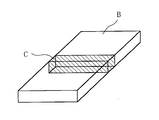
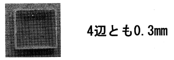
- FIG. 4 is a diagram showing a collection position of a test sample C in an example corresponding to the first embodiment.
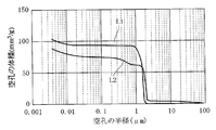
- FIG. 3 is a graph showing a distribution state of pores (open pores) before and after a SiC conversion reaction test in an example corresponding to the first embodiment.
- FIG. The photograph which shows the state after ashing of the test sample A (unprocessed product) after the SiC conversion reaction test in the Example corresponding to Embodiment 1.
- FIG. 1 The photograph which shows the state after ashing of the test sample B (unprocessed goods) after the SiC conversion reaction test in the Example corresponding to Embodiment 1.
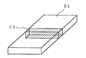
- FIG. 6 is a diagram showing a sampling position of a test sample C1 in an example corresponding to the second embodiment.
- the graph which shows the distribution state of the pore (open-pore) before and behind the SiC conversion reaction test in the Example corresponding to Embodiment 2.
- FIG. The photograph which shows the state after ashing of test sample A1 (this invention processed product) after the SiC conversion reaction test in the Example corresponding to Embodiment 2.
- FIG. The photograph which shows the state after ashing of test sample B1 (this invention processed product) after the SiC conversion reaction test in the Example corresponding to Embodiment 2.
- FIG. 1 The photograph which shows the state after ashing of test sample A1 (unprocessed goods) after the SiC conversion reaction test in the Example corresponding to Embodiment 2.
- FIG. 2 The photograph which shows the state after ashing of test sample B1 (unprocessed goods) after the SiC conversion reaction test in the Example corresponding to Embodiment 2.
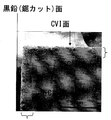
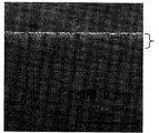
- FIG. The SEM photograph of test sample B1 (this invention processed product) after the SiC conversion reaction test in the Example corresponding to Embodiment 2.
- FIG. The SEM photograph of test sample C1 (this invention processed product) after the SiC conversion reaction test in the Example corresponding to Embodiment 2.
- test sample A1 unprocessed goods
- SiC conversion reaction test in the Example corresponding to Embodiment 2 The SEM photograph of test sample C1 (unprocessed product) after the SiC conversion reaction test in the Example corresponding to Embodiment 2.
- FIG. 1 is a longitudinal sectional view of an example of a graphite crucible for a single crystal pulling apparatus according to Embodiment 1.
- FIG. The graphite crucible 2 holding the quartz crucible 1 is composed of a graphite crucible base material 3 as a graphite crucible molded body and a coating made of a carbonized product of phenol resin formed on the entire surface of the graphite crucible base 3 (hereinafter referred to as a phenol resin coating). 4).
- the graphite crucible base material 3 has a bulk density of 1.70 Mg / m 3 or more and a bending strength of 30 MPa in consideration of the mechanical strength necessary for the crucible and considering the ease of impregnation with phenol resin. As described above, those having a Shore hardness value of 40 or more are used.
- the carbonized material which comprises the film 4 may be a graphitized material in which part or all of the carbonized material has been graphitized.
- the shape of the graphite crucible 2 is generally cup-shaped, and continues to the bottom portion 2a, a curved portion (small R portion) 2b that rises upward while being continuously curved to the bottom portion 2a, and a curved portion 2b. And a straight body portion 2c extending straight upward.
- the shape of the graphite crucible base material 3 also corresponds to the shape of the graphite crucible 2, and is composed of a bottom portion 3a, a curved portion (small R portion) 3b, and a straight body portion 3c.
- the phenol resin film may be formed on the entire surface of the graphite crucible base material 3 as shown in FIG. It may be.
- only the inner surface of the crucible may be formed as a whole, or only the curved portion (small R portion) 3b of the inner surface, or only the curved portion 3b and the straight barrel portion 3c may be formed.
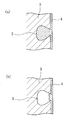
- FIG. 2 is a partially enlarged cross-sectional view of the surface of the graphite crucible base material 3 according to Embodiment 1.
- FIG. 2 (a) shows that the phenol resin coating 4 is well formed on the entire surface of the graphite crucible base material 3.
- FIG. 5B schematically shows a situation where the formation is not good.
- the graphite crucible base material 3 has minute pores on the surface, which are called open pores 5 as shown in the figure, but the open pores 5 form depressions on the surface. Therefore, the surface area of the graphite crucible base material 3 is larger than the apparent surface, and it is necessary to impregnate the inside of the depression with a phenol resin as shown in FIG. is there.
- the phenol resin impregnation when the phenol resin impregnation only covers the opening of the open pore 5 as shown in FIG. 2 (b) and the interior cannot be sufficiently filled, the above-mentioned opening that is unstable in strength is used. There is a risk of cracking the part and exposing the inner part not covered with the phenol resin to the outside in the presence of SiO gas. Therefore, in the present invention, the phenol resin impregnation was performed under the following viscosity, immersion conditions, and curing conditions of the phenol resin liquid.
- the graphite crucible having the above configuration was manufactured as follows.
- the graphite crucible base material is immersed in a phenol resin solution having a viscosity of 100 mPa ⁇ s (18 ° C.) or higher and 400 mPa ⁇ s (18 ° C.) or lower for 12 hours or more at room temperature and normal pressure.
- the phenolic resin was hardened by taking out and heat-treated, and the hardened phenolic resin was further heat-treated to carbonize the phenolic resin. Prior to the curing step, it is preferable to wipe off excess phenol resin on the surface of the graphite crucible base material.
- the graphite crucible base material on which the phenol resin film is formed is heat-treated in a halogen gas atmosphere to be highly purified after the curing step. This is because impurities generated from the graphite crucible can be reduced during the single crystal pulling operation, and a high-quality metal single crystal can be obtained.
- a graphite crucible covered with a coating made of a carbonized product of phenol resin sufficiently impregnated to the inside of the substrate could be obtained by the above-described phenol resin impregnation / curing / carbonization treatment.
- the carbonized product of the phenol resin impregnated into the inner surfaces of many open pores existing on the surface of the graphite crucible base material effectively suppresses the reaction between C and SiO gas over the entire surface of the graphite crucible base material.
- the progress of SiC can be suppressed.
- the service life of the graphite crucible can be extended.
- the graphite crucible coated with the phenol resin is heat-treated in a halogen gas atmosphere to be highly purified. This is because impurities generated from the graphite crucible can be reduced and a high-quality metal single crystal can be obtained.
- the graphite crucible for a single crystal pulling apparatus is the target of surface treatment.
- a graphite member used for synthetic quartz production for example, graphite used for synthetic quartz production.
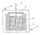
- the lid 11, and the like a film made of a carbonized product of a phenol resin may be formed on the surface by phenol resin impregnation / curing / carbonization treatment as in the first embodiment.
- FIG. 3 12 is a rod-shaped body, 13 is a heater, 14 is an inert gas introduction port, and 15 is an exhaust port.
- FIG. 4 is a longitudinal sectional view of an example of a graphite crucible for a single crystal pulling apparatus according to the second embodiment.
- the graphite crucible 2 holding the quartz crucible 1 is composed of a graphite crucible base 3 as a graphite crucible molded body and a pyrolytic carbon coating 4A formed on the entire surface of the graphite crucible base 3.
- the graphite crucible base material 3 has a bulk density of 1.65 Mg / m 3 or more and a bending strength in consideration of the mechanical strength necessary for the crucible and considering the ease of precipitation of pyrolytic carbon. Have a value of 30 MPa or more and a Shore hardness of 40 or more.
- the shape of the graphite crucible 2 is generally cup-shaped, and continues to the bottom portion 2a, a curved portion (small R portion) 2b that rises upward while being continuously curved to the bottom portion 2a, and a curved portion 2b.
- the straight body 2c extends straight upward.
- the shape of the graphite crucible base material 3 also corresponds to the shape of the graphite crucible 2, and is composed of a bottom portion 3a, a curved portion (small R portion) 3b, and a straight body portion 3c.
- the pyrolytic carbon film may be formed on the entire surface of the graphite crucible base material 3 as shown in FIG. It may be only. For example, only the inner surface of the crucible may be deposited as a whole, or may be deposited only on the curved portion (small R portion) 3b or only on the curved portion 3b and the straight body portion 3c.
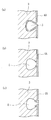
- FIG. 5 is a partially enlarged cross-sectional view of the surface of the graphite crucible base material 3 according to Embodiment 2.
- FIG. 5 (a) shows that the pyrolytic carbon coating 4A is satisfactorily formed on the entire surface of the graphite crucible base material 3.
- the situation is shown schematically, and FIGS. 5B and 5C schematically show the situation where the formation is not good.
- the graphite crucible base material 3 has minute holes on the surface, which are called open pores 5 as shown in the figure, but the open pores 5 form depressions on the surface. Therefore, the surface area of the graphite crucible base material 3 is larger than it appears, and it is necessary to sufficiently cover the inside of the depression with a pyrolytic carbon film as shown in FIG. There is.
- the deposition rate of the pyrolytic carbon film be 0.2 ⁇ m / h or less. In order to obtain such a thin pyrolytic carbon film with a slow deposition rate, the CVI method is suitable.
- a graphite crucible covered with a pyrolytic carbon film sufficiently impregnated into the inside of the substrate could be obtained by using the CVI method.
- the pyrolytic carbon is deposited and filled to the inner surfaces of many open pores existing on the surface of the graphite crucible base material, so that the reaction between C and SiO gas is effective over the entire surface of the graphite crucible base material. It is suppressed and progress of SiC formation can be suppressed. As a result, the service life of the graphite crucible can be extended.
- the graphite crucible for a single crystal pulling apparatus is the target of surface treatment.
- a graphite member used for manufacturing synthetic quartz for example, graphite used for manufacturing synthetic quartz.
- the lid 11, and the like a pyrolytic carbon film may be formed on the surface by the CVI method as in the second embodiment.
- the SiO 2 gas that is generated causes SiC to progress, the dimensions change, and the material becomes brittle, causing micron cracks.
- the occurrence of cracks has been a problem, but by forming a pyrolytic carbon film on the surface by the CVI method, the formation of SiC can be suppressed and the life can be extended.
- Test Example 1 The following test samples were examined for changes in dimensions.
- the graphite material was surface-treated with the same phenol resin impregnation / curing / carbonization treatment as in the first embodiment, and the surface-treated graphite material and two types of untreated graphite material that were not surface-treated were tested. Samples of the following shapes were prepared for use. Divided pieces of three-part graphite crucible: each one piece
- a divided piece using a surface-treated graphite material is referred to as a treated product of the present invention
- a divided piece using an untreated graphite material is referred to as an untreated product.
- the phenol resin impregnation / curing treatment was performed as follows. Viscosity of the phenol resin solution used: 195 mPa ⁇ s (18 ° C) Immersion conditions: The test sample was immersed in the phenol resin solution for 24 hours at room temperature and normal pressure. Curing conditions: The temperature was gradually raised so as not to foam, the temperature was raised to 200 ° C., and then held at 200 ° C. for curing. In addition, the sample for a test after hardening was heated at 2000 degreeC by halogen gas atmosphere, and the highly purified process (equivalent to the carbonization process of a phenol resin) was performed.
- Table 1 shows the results of changes in the height, inner diameters of 50 mm and 150 mm from the upper end of the crucible, and changes in the radius of the small R portion of the processed and untreated products of the present invention.
- Test Example 2 The following test samples were subjected to a SiC conversion reaction test to examine changes in physical properties (bulk density, hardness, electrical resistivity, bending strength, pore (open pore) distribution) before and after the SiC reaction.
- test sample Except for the difference in shape, two kinds of processed products of the present invention similar to Test Example 1 and untreated products were produced as test samples.
- a test sample one having the following shape was used.
- 10 ⁇ 10 ⁇ 60 (mm) rod-shaped sample Hereinafter, this rod-shaped sample is referred to as a test sample A.
- 100 ⁇ 200 ⁇ 20 (mm) plate-like sample Hereinafter, this plate-like sample is referred to as a test sample B.
- this cut piece is referred to as a test sample C.
- test samples A and B are used as respective samples of test examples 3 and 4 to be described later in addition to test example 2, and test sample C is a scanning electron microscope (SEM) of test example 4 to be described later.
- SEM scanning electron microscope
- SiC conversion reaction test Test samples A to C were subjected to high-temperature heat treatment with synthetic quartz (high purity SiO 2 ), and the reactivity of SiC conversion was compared. Specific conditions in this case are as follows. Processing furnace: Vacuum furnace Processing temperature: 1600 ° C Furnace pressure: 10 Torr Processing gas: Ar 1 ml / min Treatment time: Hold for 8 hours Treatment method: A test sample is embedded in synthetic quartz powder and heat treated.
- Test results Since physical properties before and after the surface treatment (bulk density, hardness, electrical resistivity, bending strength) were examined, the measurement results of the test sample A are shown in Table 2, and the measurement results of the test sample B are shown in Table 3. Show. Moreover, the measurement result of pore (open pore) distribution is shown in FIG.
- the test piece for a measurement was extract
- L1 represents the distribution of the processed product of the present invention
- L2 represents the distribution of the untreated product.
- the treated product of the present invention had a small pore volume.
- Test Example 3 With respect to test samples A and B for which the SiC conversion reaction test of Test Example 2 was conducted, the mass change and volume change before and after the SiC reaction were examined. (Test results) Table 4 shows the measurement results of mass change and volume change before and after the SiC reaction test.
- Test Example 4 For test samples A to C in which the same SiC reaction test as in Test Example 4 was performed, the thickness of the SiC layer after the reaction test was as follows: (1) Observation after ashing, (2) Scanning electron microscope Observation was performed by two methods.
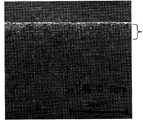
- FIGS. 8 is a photograph showing the state after ashing of test sample A (processed product of the present invention)
- FIG. 9 is a photograph showing the state of test sample B (processed product of the present invention) after ashing
- FIG. I is a photograph showing a state after ashing of test sample A (untreated product)
- FIG. 11 is a photograph showing a state after ashing of test sample B (untreated product).
- the treated product of the present invention is more effective in suppressing SiC formation than the untreated product. Although there was a difference in the value of the SiC layer depending on the sample size, the SiC layer was about 50% thinner in the treated product of the present invention than in the untreated product.
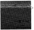
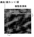
- FIGS. 12 to 16 show SEM photographs of the surface states of test samples A to C after the SiC reaction test.
- 12 is a SEM photograph of test sample A (processed product of the present invention)
- FIG. 13 is a SEM photograph of test sample B (processed product of the present invention)
- FIG. 14 is a test sample C (processed product of the present invention).
- FIG. 15 is a SEM photograph of the test sample A (untreated product)
- FIG. 16 is a SEM photograph of the test sample C (untreated product). 12 to 16, “ ⁇ ” indicates a SiC layer.
- Test Example 1 The following test samples were examined for changes in dimensions.
- the graphite material is surface-treated by the CVI method similar to that of the second embodiment, and two types of the surface-treated graphite material and an untreated graphite material that has not been surface-treated are subjected to a sample having the following shape for testing.
- a divided piece using a surface-treated graphite material is referred to as a treated product of the present invention
- a divided piece using an untreated graphite material is referred to as an untreated product.
- CVI processing The CVI process was performed as follows. That is, after placing the graphite material in a vacuum furnace and raising the temperature to 1100 ° C., CH 4 gas was allowed to flow at a flow rate of 10 (l / min) while maintaining the pressure at 10 Torr for 100 hours.
- Table 6 shows the results obtained by examining changes in height, inner diameters of 50 mm and 150 mm from the upper end of the crucible, and changes in the radius of the small R portion of the processed and untreated products of the present invention.
- Test Example 2 The following test samples were subjected to a SiC conversion reaction test to examine changes in physical properties (bulk density, hardness, electrical resistivity, bending strength, pore (open pore) distribution) before and after the SiC reaction.
- test sample Except for the difference in shape, two kinds of processed products of the present invention similar to Test Example 1 and untreated products were produced as test samples.
- a test sample one having the following shape was used.
- 10 ⁇ 10 ⁇ 60 (mm) rod-shaped sample Hereinafter, this rod-shaped sample is referred to as a test sample A1.
- 100 ⁇ 200 ⁇ 20 (mm) plate-like sample Hereinafter, this plate-like sample is referred to as test sample B1.
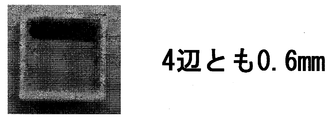
- this cut piece is referred to as a test sample C1.
- test samples A1 and B1 are used as respective samples of Test Examples 3 and 4 described later in addition to the Test Example 2, and the test sample C1 is a scanning electron microscope (SEM) of Test Example 4 described later.
- SEM scanning electron microscope
- SiC conversion reaction test Test samples A to C were subjected to high-temperature heat treatment with synthetic quartz (high purity SiO 2 ), and the reactivity of SiC conversion was compared. Specific conditions in this case are as follows. Processing furnace: Vacuum furnace Processing temperature: 1600 ° C Furnace pressure: 10 Torr Processing gas: Ar 1 ml / min Treatment time: Hold for 8 hours Treatment method: A test sample is embedded in synthetic quartz powder and heat treated.
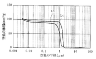
- Test results Since physical properties (bulk density, hardness, electrical resistivity, bending strength) before and after the surface treatment were examined for the test samples A1 and B1, the measurement results are shown in Tables 7 and 8. Moreover, the measurement result of pore (open pore) distribution is shown in FIG.
- the test piece for a measurement was extract
- L3 indicates the distribution of the processed product of the present invention
- L4 indicates the distribution of the unprocessed product.
- the volume of large pores of the treated product of the present invention was reduced.
- CVI had a small pore size.
- Test Example 3 Regarding the test samples A1 and B1 for which the SiC conversion reaction test of Test Example 2 was performed, the mass change and the volume change before and after the SiC reaction were examined. (Test results) Table 9 shows the measurement results of mass change and volume change before and after the SiC reaction test.
- Test Example 4 For the test samples A1 to C1 in which the same SiC reaction test as in Test Example 4 was performed, the thickness of the SiC layer after the reaction test was as follows: (1) observation after ashing, (2) by scanning electron microscope Observation was performed by two methods.
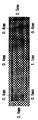
- FIGS. 19 to 22 show the states after the ashing of the test samples A1 and B1.
- 19 is a photograph showing the state after ashing of the test sample A1 (processed product of the present invention)
- FIG. 20 is a photograph showing the state of the test sample B1 (processed product of the present invention) after ashing
- FIG. I is a photograph showing the state after ashing of the test sample A1 (untreated product)
- FIG. 22 is a photograph showing the state after ashing of the test sample B1 (untreated product).
- the treated product of the present invention has an effect of suppressing the formation of SiC as compared with the untreated product. Although there was a difference in the value of the SiC layer depending on the sample size, the SiC layer was about 50% thinner in the treated product of the present invention than in the untreated product.
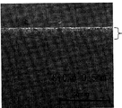
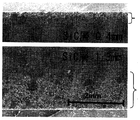
- FIGS. 23 to 27 show SEM photographs of the surface states of test samples A1 to C1 after the SiC reaction test.
- 23 is an SEM photograph of test sample A1 (processed product of the present invention)
- FIG. 24 is an SEM photograph of test sample B1 (processed product of the present invention)
- FIG. 25 is a test sample C1 (processed product of the present invention).
- 26 is an SEM photograph of the test sample A1 (untreated product)
- FIG. 27 is an SEM photograph of the test sample C1 (untreated product).
- “ ⁇ ” indicates a SiC layer. (Evaluation of test results) From the SEM photograph, the thickness of the SiC layer showed the same tendency as the result of ashing. The effect of the treated product of the present invention was confirmed compared to the untreated product.
- the present invention is applied to a graphite crucible for a single crystal pulling apparatus and a method for manufacturing the same.
- Quartz crucible 2 Graphite crucible 3: Graphite crucible base material 4: Phenolic resin coating 4A: Pyrolytic carbon coating 5: Open pores
Landscapes
- Chemical & Material Sciences (AREA)
- Engineering & Computer Science (AREA)
- Ceramic Engineering (AREA)
- Materials Engineering (AREA)
- Organic Chemistry (AREA)
- Structural Engineering (AREA)
- Crystallography & Structural Chemistry (AREA)
- Metallurgy (AREA)
- Manufacturing & Machinery (AREA)
- Inorganic Chemistry (AREA)
- Crystals, And After-Treatments Of Crystals (AREA)
Abstract
Priority Applications (4)
| Application Number | Priority Date | Filing Date | Title |
|---|---|---|---|
| US13/980,995 US20130305984A1 (en) | 2011-02-02 | 2010-01-30 | Graphite crucible for single crystal pulling apparatus and method of manufacturing same |
| CN201280003981.4A CN103249876B (zh) | 2011-02-02 | 2012-01-30 | 单晶提拉装置用石墨坩埚及其制造方法 |
| KR1020137023197A KR101808891B1 (ko) | 2011-02-02 | 2012-01-30 | 단결정 인상 장치용 흑연 도가니 및 그 제조 방법 |
| KR1020177035272A KR101907818B1 (ko) | 2011-02-02 | 2012-01-30 | 단결정 인상 장치용 흑연 도가니 및 그 제조 방법 |
Applications Claiming Priority (4)
| Application Number | Priority Date | Filing Date | Title |
|---|---|---|---|
| JP2011-020814 | 2011-02-02 | ||
| JP2011-020813 | 2011-02-02 | ||
| JP2011020814A JP5723615B2 (ja) | 2011-02-02 | 2011-02-02 | 単結晶引上げ装置用黒鉛ルツボ及びその製造方法 |
| JP2011020813A JP5777897B2 (ja) | 2011-02-02 | 2011-02-02 | 単結晶引上げ装置用黒鉛ルツボ及びその製造方法 |
Publications (1)
| Publication Number | Publication Date |
|---|---|
| WO2012105488A1 true WO2012105488A1 (fr) | 2012-08-09 |
Family
ID=46602702
Family Applications (1)
| Application Number | Title | Priority Date | Filing Date |
|---|---|---|---|
| PCT/JP2012/051975 Ceased WO2012105488A1 (fr) | 2011-02-02 | 2012-01-30 | Creuset en graphite pour un appareil de tirage de monocristal et procédé de fabrication du creuset en graphite |
Country Status (5)
| Country | Link |
|---|---|
| US (1) | US20130305984A1 (fr) |
| KR (2) | KR101907818B1 (fr) |
| CN (1) | CN103249876B (fr) |
| TW (2) | TWI576472B (fr) |
| WO (1) | WO2012105488A1 (fr) |
Cited By (2)
| Publication number | Priority date | Publication date | Assignee | Title |
|---|---|---|---|---|
| US20160208406A1 (en) * | 2013-09-25 | 2016-07-21 | Lg Siltron Inc. | Crucible and ingot growing device comprising same |
| CN118851788A (zh) * | 2024-09-27 | 2024-10-29 | 湖南德智新材料有限公司 | 一种掺杂型c/c复合材料坩埚的制备方法及其应用 |
Families Citing this family (5)
| Publication number | Priority date | Publication date | Assignee | Title |
|---|---|---|---|---|
| DE102014226642A1 (de) | 2014-12-19 | 2016-06-23 | Brose Fahrzeugteile Gmbh & Co. Kg, Coburg | Fahrzeugsitzbaugruppe mit Rückstelleinrichtung |
| CN108441842A (zh) * | 2018-05-24 | 2018-08-24 | 山东伟基炭科技有限公司 | 一种带抗氧化涂层管式pecvd石墨舟及制造方法 |
| DE102020115575A1 (de) | 2020-06-12 | 2021-12-16 | Otto Bock Healthcare Products Gmbh | Prothesenhand |
| CN112624782A (zh) * | 2020-12-11 | 2021-04-09 | 包头美科硅能源有限公司 | 一种埚帮涂层的使用方法 |
| KR20230083437A (ko) * | 2021-12-03 | 2023-06-12 | 인동첨단소재(주) | 그라파이트 시트를 이용한 흑연 도가니의 제조방법. |
Citations (3)
| Publication number | Priority date | Publication date | Assignee | Title |
|---|---|---|---|---|
| JPH02172887A (ja) * | 1988-12-26 | 1990-07-04 | Toshiba Ceramics Co Ltd | 単結晶製造用カーボンルツボ |
| JP2002145693A (ja) * | 2000-11-01 | 2002-05-22 | Tokai Carbon Co Ltd | 単結晶引き上げ用c/cルツボとその製造方法 |
| JP2004059332A (ja) * | 2002-07-25 | 2004-02-26 | Toyo Tanso Kk | 単結晶引き上げ用黒鉛材料及びその製造方法 |
Family Cites Families (5)
| Publication number | Priority date | Publication date | Assignee | Title |
|---|---|---|---|---|
| US4226900A (en) * | 1978-03-03 | 1980-10-07 | Union Oil Company Of California | Manufacture of high density, high strength isotropic graphite |
| JP3653647B2 (ja) * | 1996-05-31 | 2005-06-02 | イビデン株式会社 | シリコン単結晶引き上げ装置用の保温筒 |
| JP3116005B2 (ja) * | 1996-11-26 | 2000-12-11 | 日本カーボン株式会社 | 半導体単結晶引上げ用c/c製ルツボの製法 |
| JP2005225718A (ja) | 2004-02-13 | 2005-08-25 | Shin Etsu Handotai Co Ltd | 黒鉛ルツボ及び黒鉛ルツボの管理方法 |
| KR101456904B1 (ko) | 2009-05-26 | 2014-10-31 | 가부시키가이샤 인큐베이션 얼라이언스 | 탄소 재료 및 그 제조 방법 |
-
2010
- 2010-01-30 US US13/980,995 patent/US20130305984A1/en not_active Abandoned
-
2012
- 2012-01-30 KR KR1020177035272A patent/KR101907818B1/ko active Active
- 2012-01-30 KR KR1020137023197A patent/KR101808891B1/ko not_active Expired - Fee Related
- 2012-01-30 CN CN201280003981.4A patent/CN103249876B/zh active Active
- 2012-01-30 WO PCT/JP2012/051975 patent/WO2012105488A1/fr not_active Ceased
- 2012-02-01 TW TW104132396A patent/TWI576472B/zh not_active IP Right Cessation
- 2012-02-01 TW TW101103242A patent/TWI526585B/zh not_active IP Right Cessation
Patent Citations (3)
| Publication number | Priority date | Publication date | Assignee | Title |
|---|---|---|---|---|
| JPH02172887A (ja) * | 1988-12-26 | 1990-07-04 | Toshiba Ceramics Co Ltd | 単結晶製造用カーボンルツボ |
| JP2002145693A (ja) * | 2000-11-01 | 2002-05-22 | Tokai Carbon Co Ltd | 単結晶引き上げ用c/cルツボとその製造方法 |
| JP2004059332A (ja) * | 2002-07-25 | 2004-02-26 | Toyo Tanso Kk | 単結晶引き上げ用黒鉛材料及びその製造方法 |
Cited By (2)
| Publication number | Priority date | Publication date | Assignee | Title |
|---|---|---|---|---|
| US20160208406A1 (en) * | 2013-09-25 | 2016-07-21 | Lg Siltron Inc. | Crucible and ingot growing device comprising same |
| CN118851788A (zh) * | 2024-09-27 | 2024-10-29 | 湖南德智新材料有限公司 | 一种掺杂型c/c复合材料坩埚的制备方法及其应用 |
Also Published As
| Publication number | Publication date |
|---|---|
| KR20170139174A (ko) | 2017-12-18 |
| US20130305984A1 (en) | 2013-11-21 |
| TWI576472B (zh) | 2017-04-01 |
| TW201245510A (en) | 2012-11-16 |
| KR101907818B1 (ko) | 2018-10-12 |
| KR101808891B1 (ko) | 2017-12-13 |
| CN103249876A (zh) | 2013-08-14 |
| KR20140022004A (ko) | 2014-02-21 |
| TW201602429A (zh) | 2016-01-16 |
| TWI526585B (zh) | 2016-03-21 |
| CN103249876B (zh) | 2016-06-29 |
Similar Documents
| Publication | Publication Date | Title |
|---|---|---|
| EP2520691B1 (fr) | Matériau en carbone revêtu de carbure de tantale et procédé de fabrication associé | |
| WO2012105488A1 (fr) | Creuset en graphite pour un appareil de tirage de monocristal et procédé de fabrication du creuset en graphite | |
| CN101680112A (zh) | 借助多层生长导向器的直径导向式SiC升华生长 | |
| CN114572975A (zh) | 碳化钽涂层碳材料及其制备方法 | |
| KR100427118B1 (ko) | 열처리용지그및그제조방법 | |
| CN118581444A (zh) | 一种制备SiC涂层的方法 | |
| JP4071919B2 (ja) | SiC被覆黒鉛部材およびその製造方法 | |
| JP2005281085A (ja) | 黒鉛製るつぼ | |
| JP2000302577A (ja) | 炭化珪素被覆黒鉛部材 | |
| JP5723615B2 (ja) | 単結晶引上げ装置用黒鉛ルツボ及びその製造方法 | |
| JP2000351689A (ja) | 熱分解炭素被覆炭素繊維強化炭素複合材料及び単結晶引き上げ装置用部品 | |
| JP5777897B2 (ja) | 単結晶引上げ装置用黒鉛ルツボ及びその製造方法 | |
| JP2000302576A (ja) | 炭化珪素被覆黒鉛材 | |
| EP4653588A1 (fr) | Procédé de fabrication d'un substrat épitaxial de 3c-sic monocristallin, procédé de fabrication d'un substrat autoporteur de 3c-sic, et substrat épitaxial de 3c-sic monocristallin | |
| JP2000095567A (ja) | 炭素繊維強化炭素複合材及び単結晶引き上げ装置用部材 | |
| JP2001158696A (ja) | 炭化珪素単結晶の製造方法 | |
| JP4358313B2 (ja) | 半導体単結晶引き上げ装置のシードチャック | |
| JP4864934B2 (ja) | 炭素質基材の表面に熱分解炭素を被覆した高温部材、その高温部材を配備してなる単結晶引上げ装置及びその高温部材の製造方法 | |
| Locher et al. | Lift-off technique of homoepitaxial CVD diamond films by deep implantation and selective etching | |
| TWI912001B (zh) | 耐高溫裝置及其製造方法 | |
| JP4218853B2 (ja) | 単結晶引き上げ用炭素質ルツボとその製造方法 | |
| CN115819099A (zh) | 一种高性能SiCf/SiC复合材料的制备方法 | |
| JPH09235163A (ja) | 熱処理用治具およびその製造方法 | |
| JPH07223884A (ja) | 自己修復型耐酸化性被覆を有する炭素材料 | |
| HK1105096B (en) | Tantalum carbide-covered carbon material and process for producing the same |
Legal Events
| Date | Code | Title | Description |
|---|---|---|---|
| 121 | Ep: the epo has been informed by wipo that ep was designated in this application |
Ref document number: 12742204 Country of ref document: EP Kind code of ref document: A1 |
|
| WWE | Wipo information: entry into national phase |
Ref document number: 13980995 Country of ref document: US |
|
| NENP | Non-entry into the national phase |
Ref country code: DE |
|
| ENP | Entry into the national phase |
Ref document number: 20137023197 Country of ref document: KR Kind code of ref document: A |
|
| 122 | Ep: pct application non-entry in european phase |
Ref document number: 12742204 Country of ref document: EP Kind code of ref document: A1 |