WO2012105507A1 - 自動変速機の油圧制御装置 - Google Patents
自動変速機の油圧制御装置 Download PDFInfo
- Publication number
- WO2012105507A1 WO2012105507A1 PCT/JP2012/052010 JP2012052010W WO2012105507A1 WO 2012105507 A1 WO2012105507 A1 WO 2012105507A1 JP 2012052010 W JP2012052010 W JP 2012052010W WO 2012105507 A1 WO2012105507 A1 WO 2012105507A1
- Authority
- WO
- WIPO (PCT)
- Prior art keywords
- pressure
- line pressure
- solenoid valve
- hydraulic
- linear solenoid
- Prior art date
- Legal status (The legal status is an assumption and is not a legal conclusion. Google has not performed a legal analysis and makes no representation as to the accuracy of the status listed.)
- Ceased
Links
Images


Classifications
-
- F—MECHANICAL ENGINEERING; LIGHTING; HEATING; WEAPONS; BLASTING
- F16—ENGINEERING ELEMENTS AND UNITS; GENERAL MEASURES FOR PRODUCING AND MAINTAINING EFFECTIVE FUNCTIONING OF MACHINES OR INSTALLATIONS; THERMAL INSULATION IN GENERAL
- F16H—GEARING
- F16H61/00—Control functions within control units of change-speed- or reversing-gearings for conveying rotary motion ; Control of exclusively fluid gearing, friction gearing, gearings with endless flexible members or other particular types of gearing
- F16H61/0021—Generation or control of line pressure
- F16H61/0025—Supply of control fluid; Pumps therefor
-
- F—MECHANICAL ENGINEERING; LIGHTING; HEATING; WEAPONS; BLASTING
- F16—ENGINEERING ELEMENTS AND UNITS; GENERAL MEASURES FOR PRODUCING AND MAINTAINING EFFECTIVE FUNCTIONING OF MACHINES OR INSTALLATIONS; THERMAL INSULATION IN GENERAL
- F16H—GEARING
- F16H61/00—Control functions within control units of change-speed- or reversing-gearings for conveying rotary motion ; Control of exclusively fluid gearing, friction gearing, gearings with endless flexible members or other particular types of gearing
- F16H61/0021—Generation or control of line pressure
-
- F—MECHANICAL ENGINEERING; LIGHTING; HEATING; WEAPONS; BLASTING
- F16—ENGINEERING ELEMENTS AND UNITS; GENERAL MEASURES FOR PRODUCING AND MAINTAINING EFFECTIVE FUNCTIONING OF MACHINES OR INSTALLATIONS; THERMAL INSULATION IN GENERAL
- F16H—GEARING
- F16H61/00—Control functions within control units of change-speed- or reversing-gearings for conveying rotary motion ; Control of exclusively fluid gearing, friction gearing, gearings with endless flexible members or other particular types of gearing
- F16H61/02—Control functions within control units of change-speed- or reversing-gearings for conveying rotary motion ; Control of exclusively fluid gearing, friction gearing, gearings with endless flexible members or other particular types of gearing characterised by the signals used
- F16H61/0202—Control functions within control units of change-speed- or reversing-gearings for conveying rotary motion ; Control of exclusively fluid gearing, friction gearing, gearings with endless flexible members or other particular types of gearing characterised by the signals used the signals being electric
- F16H61/0204—Control functions within control units of change-speed- or reversing-gearings for conveying rotary motion ; Control of exclusively fluid gearing, friction gearing, gearings with endless flexible members or other particular types of gearing characterised by the signals used the signals being electric for gearshift control, e.g. control functions for performing shifting or generation of shift signal
- F16H61/0206—Layout of electro-hydraulic control circuits, e.g. arrangement of valves
-
- Y—GENERAL TAGGING OF NEW TECHNOLOGICAL DEVELOPMENTS; GENERAL TAGGING OF CROSS-SECTIONAL TECHNOLOGIES SPANNING OVER SEVERAL SECTIONS OF THE IPC; TECHNICAL SUBJECTS COVERED BY FORMER USPC CROSS-REFERENCE ART COLLECTIONS [XRACs] AND DIGESTS
- Y10—TECHNICAL SUBJECTS COVERED BY FORMER USPC
- Y10T—TECHNICAL SUBJECTS COVERED BY FORMER US CLASSIFICATION
- Y10T74/00—Machine element or mechanism
- Y10T74/20—Control lever and linkage systems
- Y10T74/20012—Multiple controlled elements
- Y10T74/20018—Transmission control
- Y10T74/20024—Fluid actuator
Definitions
- the present invention is a line pressure adjusting means for adjusting a line pressure serving as a base pressure for oil pressure control, and a linear for adjusting an oil pressure for engaging a frictional engagement element with a required engagement force based on the line pressure.
- the present invention relates to a hydraulic control device for an automatic transmission provided with a solenoid valve.
- the vehicle is provided with a transmission gear mechanism that transmits drive power at a predetermined gear ratio from the input shaft side to the output shaft side by selectively engaging a plurality of frictional engagement elements (clutch or brake).
- a machine and a hydraulic control device for controlling the hydraulic pressure for engaging the above-mentioned friction engagement element are provided.
- the hydraulic control device of such an automatic transmission is designed to realize a plurality of shift speeds by combining the engagement and disengagement of the respective frictional engagement elements.
- the regulator valve (line pressure adjustment means) that regulates the line pressure that is the base pressure for engaging the coupling element, and the plurality of friction engagement elements by regulating the hydraulic oil adjusted to the line pressure by the regulator valve And a linear solenoid valve for adjusting the hydraulic pressure (required hydraulic pressure) for engaging any one of them with the required engagement force.
- the line pressure adjusted by the regulator valve can be switched in order to improve the fuel consumption of the vehicle.
- the hydraulic control device for automatic transmissions described in Patent Documents 1 and 2 includes a linear solenoid valve for switching the line pressure, and pressure regulation is performed by the regulator valve by on / off control of the linear solenoid valve.
- the line pressure is switched between two levels, high line pressure and low line pressure.
- the linear solenoid valve into which the hydraulic oil of the line pressure is introduced At the time of line pressure, the amount of overlap between the groove of the spool of the linear solenoid valve and the port of the valve body is different.
- the hydraulic pressure (required hydraulic pressure) set by the linear solenoid valve according to the required engagement force (engagement pressure) of the frictional engagement element is higher for the same current value for controlling the linear solenoid valve.
- the hydraulic pressure is different between the line pressure and the low line pressure. Then, the engagement pressure of the frictional engagement element changes with the switching of the line pressure, so that a shift shock is generated, which may cause a drop in shift productability.
- the present invention has been made in view of the above-mentioned point, and its object is to maintain the hydraulic pressure regulated by the linear solenoid valve for different line pressures at a constant pressure by simple control. It is an object of the present invention to provide a hydraulic control system of an automatic transmission which can prevent the occurrence of a shift shock accompanying the change (switching) of.
- the present invention for solving the above problems has a driving force transmission mechanism (3) for transmitting a driving force at a predetermined gear ratio by selectively engaging a plurality of friction engagement elements (3a).
- a hydraulic control device for an automatic transmission comprising: an automatic transmission (7) and a hydraulic control device (6) for controlling a hydraulic pressure for engaging the friction engagement element (3a), wherein the hydraulic control device (6) is a line pressure adjusting means (23) for adjusting the line pressure serving as a base pressure for engaging the frictional engagement element (3a) from the oil pressure of the hydraulic oil supplied from the oil pressure supply source (21)
- the line pressure variable means (25) capable of changing the line pressure adjusted by the line pressure adjustment means (23) and the hydraulic oil adjusted to the line pressure by the line pressure adjustment means (23)
- Required oil pressure for engaging the frictional engagement element (3a) with the required engagement force It has a linear solenoid valve (40) for pressure regulation, and control means (10) for controlling the hydraulic pressure regulated by the linear solenoid valve (40) by controlling the value of current supplied to the linear solenoi
- control is performed to make the current value supplied to the linear solenoid valve different according to the line pressure changed by the line pressure changing means. Therefore, it is possible to keep the required oil pressure regulated by the linear solenoid valve at a constant pressure for different line pressures only by simple control to make the current values different. Therefore, since it can prevent that the engagement pressure of a frictional engagement element changes with the change of line pressure, generation
- the required hydraulic pressure adjusted by the linear solenoid valve is maintained at a constant pressure by control to change the value of the current supplied to the linear solenoid valve. Therefore, it is not necessary to switch the required hydraulic pressure according to the line pressure. Therefore, the control for preventing the occurrence of the shift shock accompanying the change of the line pressure does not become complicated.
- the line pressure variable means (25) is a line pressure switching means (25) which can adjust the pressure by switching the line pressure to at least two stages of high line pressure and low line pressure.
- the means (10) supplies the current value supplied to the linear solenoid valve (40) to adjust the same required hydraulic pressure as the current value (I) at a lower line pressure than the current value (I 1 ) at the high line pressure. It is good to control so that 2 ) becomes larger current value.
- the required oil pressure adjusted by the linear solenoid valve can be kept constant at high line pressure and low line pressure. It becomes possible. Therefore, in the hydraulic control device provided with the line pressure switching means capable of switching the line pressure to two stages of high line pressure and low line pressure, it is possible to effectively suppress the occurrence of the shift shock accompanying the switching of the line pressure. Merchandise can be guaranteed.
- symbol in the parenthesis here shows the code
- the hydraulic pressure adjusted by the linear solenoid valve can be kept constant for different line pressures by simple control. It is possible to prevent the occurrence of a shock.
- FIG. 1 is a block diagram schematically showing a power transmission system and a control system of a vehicle provided with a hydraulic control device for an automatic transmission according to an embodiment of the present invention. It is a figure which shows a part of hydraulic circuit with which a hydraulic control apparatus is provided. It is a graph which shows the relationship between the electric current value supplied to a linear solenoid valve, and the required oil pressure corresponding to it. It is a flowchart which shows the procedure of control (current value holding-over control) which changes the electric current value supplied to a linear solenoid valve.
- FIG. 1 is a block diagram schematically showing a power transmission system and a control system of a vehicle provided with a hydraulic control device for an automatic transmission according to one embodiment of the present invention.
- the power transmission system of the vehicle shown in the figure is set by inputting the rotational output of the torque converter 2 for transmitting the rotational output of the engine 1 to the transmission gear mechanism 3 and the rotational output of the torque converter 2 It includes a transmission gear mechanism (drive power transmission mechanism) 3 that shifts and outputs at a speed ratio as described above, and a differential gear mechanism 4 that distributes the rotational output of the transmission gear mechanism 3 to the drive wheels 5 and 5.
- a transmission gear mechanism drive power transmission mechanism
- differential gear mechanism 4 that distributes the rotational output of the transmission gear mechanism 3 to the drive wheels 5 and 5.
- the torque converter 2 and the transmission gear mechanism 3 constitute an automatic transmission 7, and a hydraulic control device 6 for controlling the hydraulic pressure of the hydraulic oil supplied to the automatic transmission 7 is provided.
- the hydraulic control device 6 controls the hydraulic pressure of the hydraulic fluid supplied to the transmission gear mechanism 3 to provide a plurality of hydraulic control type clutches, brakes, and other friction engagement elements (provided in the transmission gear mechanism 3) , Simply referred to as “frictional engagement element”) 3a is controlled to be engaged or released in a predetermined combination. Further, the hydraulic control device 6 controls the hydraulic pressure of the hydraulic oil supplied to the torque converter 2 to perform switching control of engagement / non-engagement of the lockup clutch 2 a of the torque converter 2.
- a control system for controlling a power transmission system of a vehicle includes a sensor (not shown) provided in each part of the vehicle, an electronic control unit (ECU) 10 to which detection values of each sensor are input, and an electronic control It comprises the hydraulic control device 6 controlled by the unit 10.
- ECU electronice control unit
- FIG. 2 is a view schematically showing a part of a hydraulic circuit provided in the hydraulic control device 6.
- the hydraulic circuit 20 shown in the figure includes an oil pump 21 which is a hydraulic pressure supply source, a regulator valve 23 which is a line pressure adjusting means, and a solenoid valve which is a line pressure variable (switching) means (hereinafter "line pressure switching valve” And 25).
- the oil pump 21 sucks up the hydraulic oil from the oil tank 30 and pumps it to the oil passage 31.
- the regulator valve 23 regulates the base oil pressure supplied from the oil pump 21 to generate a line pressure that is a base pressure of the hydraulic oil necessary for engagement of the frictional engagement element 3 a and the like.
- the line pressure switching valve 25 supplies auxiliary pressure to the regulator valve 23 in order to switch the line pressure regulated by the regulator valve 23 to a plurality of stages (two stages of high line pressure and low line pressure in the present embodiment). It is
- the line pressure switching valve 25 is opened (ON) by the control of the electronic control unit 10.
- the regulator valve 23 is controlled by the hydraulic fluid (signal pressure of low line pressure) passing through the oil passage 35 and the hydraulic fluid passing through the oil passage 33.
- the line pressure adjusted by the regulator valve 23 switches from the high line pressure to the low line pressure.
- the line pressure switching valve 25 is closed (OFF) by the control of the electronic control unit 10. Do not supply hydraulic oil (signal pressure of low line pressure).
- the regulator valve 23 is controlled only by the hydraulic oil passing through the oil passage 33.
- the line pressure is switched from the low line pressure to the high line pressure.
- the line pressure can be switched to two stages of high line pressure and low line pressure.
- the hydraulic oil adjusted to the line pressure by the regulator valve 23 passes through various valves such as a manual valve 36, a shift valve 37, and cut valves 38 and 39 installed on the downstream side via an oil passage 32, and is linear It is sent to the solenoid valve 40.
- a hydraulic pressure hereinafter referred to as "required hydraulic pressure" for engaging the frictional engagement element 3a with the required engagement force is adjusted by adding thrust generated by the solenoid to the hydraulic fluid. It is supposed to be.
- the ECU 10 controls the required oil pressure by controlling the value of the current supplied to the solenoid of the linear solenoid valve 40.
- the hydraulic oil adjusted to the required oil pressure by the linear solenoid valve 40 is sent to the frictional engagement element 3a of the transmission gear mechanism 3 to which the required oil pressure is supplied.
- the hydraulic pressure of the supplied hydraulic oil controls the engagement of a friction engagement element such as a clutch or a brake.
- the hydraulic circuit provided in the hydraulic control device 6 actually supplies the hydraulic oil to friction engagement elements such as a plurality of clutches and brakes corresponding to the respective shift speeds set by the transmission gear mechanism 3 and to these.
- the hydraulic circuit 20 shown in FIG. 2 schematically shows only a part of the hydraulic circuit 20 shown in FIG. Illustration and explanation of the other parts of the hydraulic circuit are omitted.
- the friction engagement element 3 a of the transmission gear mechanism 3 is shown as an example of the supply destination of the hydraulic oil adjusted to the required oil pressure by the linear solenoid valve 40.
- the hydraulic fluid pressure-regulated to the required oil pressure by the valve 40 is also provided by the friction converter such as another clutch or brake provided in the transmission gear mechanism 3 or the torque converter 2 by switching control of the oil passage. It is also sent to the lockup clutch 2a.
- the hydraulic control device 6 of this embodiment controls the hydraulic pressure adjusted by the linear solenoid valve 40 by controlling the value of the current supplied to the linear solenoid valve 40 by the ECU 10
- control is performed to make the current value supplied to the linear solenoid valve 40 different in accordance with the line pressure switched by the line pressure switching valve 25 in order to adjust the same required hydraulic pressure (hereinafter referred to as this control Is called "current value carry over control".
- this current value carry over control will be described in detail.
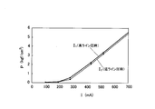
- FIG. 3 is a graph showing the relationship between the current value supplied to the linear solenoid valve 40 and the corresponding required oil pressure.
- the horizontal axis represents the current value I supplied to the linear solenoid valve 40
- the vertical axis represents the hydraulic pressure (required hydraulic pressure) P adjusted by the linear solenoid valve 40 according to the current value I.
- the current value for adjusting the same required oil pressure the current value (current value shown by a solid line) I 1 selected at high line pressure and the current selected at low line pressure
- a value (current value shown by a dotted line) I 2 As shown in this graph, the current value I 2 at low line pressure is larger than the current value I 1 at high line pressure for adjusting the same required oil pressure by the linear solenoid valve 40. It becomes.
- FIG. 4 is a flowchart showing a procedure of current value holding control performed by the hydraulic control device 6.
- the current value changeover control first, it is determined whether the line pressure condition switched by the line pressure switching valve 25 is a high line pressure (step ST1-1). As a result, if the line pressure is high (YES), the current value I 1 for high line pressure indicated by the solid line in the graph of FIG. 4 is supplied to the linear solenoid valve 40 (step ST1-2). On the other hand, if a low line pressure (NO), supplied to the linear solenoid valve 40, the current value I 2 of the low line pressure indicated by the dotted line in the graph of FIG. 4 (Step ST1-2). By performing such control, it is possible to maintain the required oil pressure adjusted by the linear solenoid valve 40 at a constant pressure when the line pressure is high and low.
- the hydraulic control device 6 of the present embodiment causes the friction engagement element 3a included in the transmission gear mechanism 3 to engage with the required engagement force. Control is performed to change the value of the current supplied to the linear solenoid valve 40 in order to adjust the required oil pressure.
- the same hydraulic pressure can be adjusted by the linear solenoid valve 40 for different line pressures with simple control, it is possible to effectively suppress the occurrence of shift shock accompanying switching of the line pressure.
- the required hydraulic pressure adjusted by the linear solenoid valve 40 can be maintained at a constant pressure only by changing the holding of the current value supplied to the linear solenoid valve 40 (changing the holding of the IP characteristics). . Therefore, it is not necessary to switch the required hydraulic pressure according to the line pressure. Therefore, the control for preventing the occurrence of the shift shock accompanying the switching of the line pressure is not complicated.
- the regulator valve 23 can adjust the line pressure in two stages of high line pressure and low line pressure, and adjusts the same required oil pressure for the friction engagement element 3a. Therefore, the current value supplied to the linear solenoid valve 40 is set such that the current value I 2 at low line pressure is larger than the current value I 1 at high line pressure (I 1 ⁇ I 2 ). ing. As described above, by increasing the current value supplied to the linear solenoid valve 40 at low line pressure than at high line pressure, the required oil pressure adjusted by the linear solenoid valve 40 can be high line pressure and low line pressure. It becomes possible to maintain a constant hydraulic pressure with time. Therefore, in the hydraulic control device 6 capable of switching the line pressure to two stages of high line pressure and low line pressure, it is possible to effectively suppress the occurrence of the shift shock accompanying the switching of the line pressure and guarantee the shift commodity property it can.
- the present invention is not limited to the above embodiment, and various modifications may be made within the scope of the claims and the technical idea described in the specification and the drawings. It is possible.
- the line pressure switching means provided in the hydraulic control device is not only switched to the two stages of high line pressure and low line pressure as described above if the line pressure can be switched to a plurality of stages, but also to multistages of three or more stages. It may be configured to switch.
Landscapes
- Engineering & Computer Science (AREA)
- General Engineering & Computer Science (AREA)
- Mechanical Engineering (AREA)
- Control Of Transmission Device (AREA)
Abstract
Description
なお、ここでの括弧内の符号は、後述する実施形態の対応する構成要素の符号を本発明の一例として示したものである。
Claims (2)
- 複数の摩擦係合要素の係合を選択的に行わせることで所定の変速比で駆動力を伝達する駆動力伝達機構を有する自動変速機と、
前記摩擦係合要素を係合させるための油圧を制御する油圧制御装置と、を備えた自動変速機の油圧制御装置であって、
前記油圧制御装置は、
油圧供給源から供給される作動油の油圧から前記摩擦係合要素を係合させるための基圧となるライン圧を調圧するライン圧調整手段と、
前記ライン圧調整手段で調圧されるライン圧を変更可能なライン圧可変手段と、
前記ライン圧調整手段でライン圧に調整された作動油を調圧することで、前記摩擦係合要素をその要求係合力で係合させるための要求油圧を調圧するリニアソレノイドバルブと、
前記リニアソレノイドバルブに供給する電流値を制御することで、該リニアソレノイドバルブで調圧する油圧を制御する制御手段と、を備え、
前記制御手段は、同一の前記要求油圧を調圧するために前記リニアソレノイドバルブに供給する電流値を前記ライン圧可変手段で変更されたライン圧に応じて異ならせる制御を行う
ことを特徴とする自動変速機の油圧制御装置。 - 前記ライン圧可変手段は、前記ライン圧を高ライン圧と低ライン圧の少なくとも2段階に切り替えて調圧可能なライン圧切替手段であり、
前記制御手段は、同一の前記要求油圧を調圧するために前記リニアソレノイドバルブに供給する電流値を、前記高ライン圧時の電流値よりも前記低ライン圧時の電流値の方が大きな電流値となるように制御する
ことを特徴とする請求項1に記載の自動変速機の油圧制御装置。
Priority Applications (4)
| Application Number | Priority Date | Filing Date | Title |
|---|---|---|---|
| CN201280004607.6A CN103314240B (zh) | 2011-02-01 | 2012-01-30 | 自动变速器的液压控制装置 |
| DE112012000638.0T DE112012000638T5 (de) | 2011-02-01 | 2012-01-30 | Öldrucksteuervorrichtung eines Automatikgetriebes |
| JP2012555866A JP5544027B2 (ja) | 2011-02-01 | 2012-01-30 | 自動変速機の油圧制御装置 |
| US13/979,423 US8886429B2 (en) | 2011-02-01 | 2012-01-30 | Oil pressure control device of automatic transmission |
Applications Claiming Priority (2)
| Application Number | Priority Date | Filing Date | Title |
|---|---|---|---|
| JP2011-020258 | 2011-02-01 | ||
| JP2011020258 | 2011-02-01 |
Publications (1)
| Publication Number | Publication Date |
|---|---|
| WO2012105507A1 true WO2012105507A1 (ja) | 2012-08-09 |
Family
ID=46602721
Family Applications (1)
| Application Number | Title | Priority Date | Filing Date |
|---|---|---|---|
| PCT/JP2012/052010 Ceased WO2012105507A1 (ja) | 2011-02-01 | 2012-01-30 | 自動変速機の油圧制御装置 |
Country Status (5)
| Country | Link |
|---|---|
| US (1) | US8886429B2 (ja) |
| JP (1) | JP5544027B2 (ja) |
| CN (1) | CN103314240B (ja) |
| DE (1) | DE112012000638T5 (ja) |
| WO (1) | WO2012105507A1 (ja) |
Families Citing this family (1)
| Publication number | Priority date | Publication date | Assignee | Title |
|---|---|---|---|---|
| CN107741542B (zh) * | 2017-10-13 | 2020-02-07 | 盛瑞传动股份有限公司 | 一种液力自动变速器的电流压力离线学习方法及测试系统 |
Citations (4)
| Publication number | Priority date | Publication date | Assignee | Title |
|---|---|---|---|---|
| JPH05319146A (ja) * | 1992-05-15 | 1993-12-03 | Toyota Motor Corp | 自動変速機の油圧制御装置 |
| JPH05322013A (ja) * | 1992-05-15 | 1993-12-07 | Toyota Motor Corp | 自動変速機の油圧制御装置 |
| JPH06201033A (ja) * | 1992-12-28 | 1994-07-19 | Mazda Motor Corp | 自動変速機の油圧制御装置 |
| JPH0791528A (ja) * | 1993-09-28 | 1995-04-04 | Mazda Motor Corp | 油圧制御装置 |
Family Cites Families (7)
| Publication number | Priority date | Publication date | Assignee | Title |
|---|---|---|---|---|
| JP3466061B2 (ja) * | 1997-09-02 | 2003-11-10 | 本田技研工業株式会社 | 車両用自動変速機の制御装置 |
| JP2002089680A (ja) * | 2000-09-18 | 2002-03-27 | Jatco Transtechnology Ltd | 自動変速機のライン圧制御装置 |
| JP4383045B2 (ja) * | 2002-12-27 | 2009-12-16 | アイシン・エィ・ダブリュ株式会社 | パワートレインの検査システム |
| CN102066813B (zh) * | 2008-07-04 | 2014-01-15 | 本田技研工业株式会社 | 自动变速器的管路压力控制装置 |
| JP2012514720A (ja) * | 2009-01-09 | 2012-06-28 | トヨタ自動車株式会社 | 車両用オンオフ制御弁の制御装置 |
| US8478497B2 (en) * | 2009-06-26 | 2013-07-02 | Toyota Jidosha Kabushiki Kaisha | Hydraulic control device and hydraulic control method for vehicle automatic transmission |
| FR2962227B1 (fr) | 2010-07-01 | 2012-07-27 | Inst Telecom Telecom Sudparis | Procede de reduction de l'eblouissement d'un recepteur recevant des signaux depuis des emetteurs |
-
2012
- 2012-01-30 DE DE112012000638.0T patent/DE112012000638T5/de not_active Ceased
- 2012-01-30 WO PCT/JP2012/052010 patent/WO2012105507A1/ja not_active Ceased
- 2012-01-30 JP JP2012555866A patent/JP5544027B2/ja not_active Expired - Fee Related
- 2012-01-30 CN CN201280004607.6A patent/CN103314240B/zh not_active Expired - Fee Related
- 2012-01-30 US US13/979,423 patent/US8886429B2/en active Active
Patent Citations (4)
| Publication number | Priority date | Publication date | Assignee | Title |
|---|---|---|---|---|
| JPH05319146A (ja) * | 1992-05-15 | 1993-12-03 | Toyota Motor Corp | 自動変速機の油圧制御装置 |
| JPH05322013A (ja) * | 1992-05-15 | 1993-12-07 | Toyota Motor Corp | 自動変速機の油圧制御装置 |
| JPH06201033A (ja) * | 1992-12-28 | 1994-07-19 | Mazda Motor Corp | 自動変速機の油圧制御装置 |
| JPH0791528A (ja) * | 1993-09-28 | 1995-04-04 | Mazda Motor Corp | 油圧制御装置 |
Also Published As
| Publication number | Publication date |
|---|---|
| CN103314240A (zh) | 2013-09-18 |
| US8886429B2 (en) | 2014-11-11 |
| JPWO2012105507A1 (ja) | 2014-07-03 |
| JP5544027B2 (ja) | 2014-07-09 |
| CN103314240B (zh) | 2015-06-24 |
| US20130298713A1 (en) | 2013-11-14 |
| DE112012000638T5 (de) | 2014-01-02 |
Similar Documents
| Publication | Publication Date | Title |
|---|---|---|
| JP5251496B2 (ja) | 自動変速機の油圧制御装置 | |
| JP5434946B2 (ja) | 油圧制御装置 | |
| JP5434945B2 (ja) | 油圧制御装置 | |
| US8292771B2 (en) | Hydraulic control apparatus of automatic transmission | |
| CN106352071B (zh) | 车辆用无级变速器的油压控制装置 | |
| WO2016013389A1 (ja) | 自動変速機の油圧制御装置 | |
| KR20080054239A (ko) | 차량용 자동 변속기의 유압 제어시스템 | |
| JP2006242347A (ja) | 車両用ロックアップクラッチ付流体式伝動装置の油圧制御装置 | |
| JP2013108576A (ja) | 車両用駆動装置の油圧制御装置 | |
| JP5544027B2 (ja) | 自動変速機の油圧制御装置 | |
| JP6394470B2 (ja) | 自動変速機の油圧制御装置 | |
| JP6094381B2 (ja) | 車両の油圧制御装置 | |
| JPWO2015122451A1 (ja) | 自動変速機の油圧制御装置 | |
| JP2016125568A (ja) | 油圧回路 | |
| JP6217558B2 (ja) | 車両用動力伝達装置の油圧制御回路 | |
| JP6405527B2 (ja) | 油圧制御装置 | |
| JP6067600B2 (ja) | 無段変速機の制御装置 | |
| JP6583083B2 (ja) | 油圧制御装置 | |
| JP2019148296A (ja) | 自動変速機の油圧回路 | |
| JP6236850B2 (ja) | ベルト式無段変速機の油圧制御装置 | |
| JP2018112240A (ja) | 自動変速機の油圧制御装置 | |
| KR100862222B1 (ko) | 무단자동변속기 | |
| KR20230030861A (ko) | 자동변속기의 유압제어장치 | |
| JP2019065965A (ja) | 自動変速機の油圧制御装置 | |
| KR20200109077A (ko) | 자동변속기 유압장치 |
Legal Events
| Date | Code | Title | Description |
|---|---|---|---|
| 121 | Ep: the epo has been informed by wipo that ep was designated in this application |
Ref document number: 12742415 Country of ref document: EP Kind code of ref document: A1 |
|
| ENP | Entry into the national phase |
Ref document number: 2012555866 Country of ref document: JP Kind code of ref document: A |
|
| WWE | Wipo information: entry into national phase |
Ref document number: 13979423 Country of ref document: US |
|
| WWE | Wipo information: entry into national phase |
Ref document number: 1301004241 Country of ref document: TH Ref document number: 112012000638 Country of ref document: DE Ref document number: 1120120006380 Country of ref document: DE |
|
| 122 | Ep: pct application non-entry in european phase |
Ref document number: 12742415 Country of ref document: EP Kind code of ref document: A1 |