WO2012107512A1 - Système hvac pour véhicule de chantier - Google Patents
Système hvac pour véhicule de chantier Download PDFInfo
- Publication number
- WO2012107512A1 WO2012107512A1 PCT/EP2012/052175 EP2012052175W WO2012107512A1 WO 2012107512 A1 WO2012107512 A1 WO 2012107512A1 EP 2012052175 W EP2012052175 W EP 2012052175W WO 2012107512 A1 WO2012107512 A1 WO 2012107512A1
- Authority
- WO
- WIPO (PCT)
- Prior art keywords
- chamber
- airflow
- hvac system
- cab
- inlet
- Prior art date
- Legal status (The legal status is an assumption and is not a legal conclusion. Google has not performed a legal analysis and makes no representation as to the accuracy of the status listed.)
- Ceased
Links
Images



Classifications
-
- B—PERFORMING OPERATIONS; TRANSPORTING
- B60—VEHICLES IN GENERAL
- B60H—ARRANGEMENTS OF HEATING, COOLING, VENTILATING OR OTHER AIR-TREATING DEVICES SPECIALLY ADAPTED FOR PASSENGER OR GOODS SPACES OF VEHICLES
- B60H1/00—Heating, cooling or ventilating devices
- B60H1/00357—Air-conditioning arrangements specially adapted for particular vehicles
- B60H1/00378—Air-conditioning arrangements specially adapted for particular vehicles for tractor or load vehicle cabins
-
- B—PERFORMING OPERATIONS; TRANSPORTING
- B60—VEHICLES IN GENERAL
- B60H—ARRANGEMENTS OF HEATING, COOLING, VENTILATING OR OTHER AIR-TREATING DEVICES SPECIALLY ADAPTED FOR PASSENGER OR GOODS SPACES OF VEHICLES
- B60H3/00—Other air-treating devices
- B60H3/06—Filtering
- B60H3/0608—Filter arrangements in the air stream
- B60H3/0616—Filter arrangements in the air stream with provisions for replacing the filter element
Definitions
- the present invention generally relates to HVAC systems and, more particularly, to an HVAC system for use with a work vehicle.
- a skid steer or wheel loader or other work vehicle is commonly used to load and move substantial volumes of dirt and like material from one location to another.
- a conventional wheel loader includes a relatively large frame that is supported for self-propelled movement over land and has a bucket or implement mounted to one end thereof. The bucket or implement can be selectively elevated to a position above side panels on a wheel loader and can be selectively tilted to "dump" materials therefrom.
- HVAC heating, ventilation and air conditioning
- Wheel loaders are often used in environments containing elevated concentrations of dust and/or moisture, which may significantly decrease the efficiency of the HVAC system, as well as reduce operator comfort.
- Filters which may be used to reduce the amount of dust and/or moisture, often suffer from shortened service lives when used to directly, e.g., exterior of the work vehicle, clean the ambient air, especially in environments having enhanced levels of airborne dust or other particulate matter.
- the operator is positioned in close proximity to the motor and other components of the work vehicle, and thus, subjected to the noise generated by the work vehicle and components.
- baffles it is known to use baffles to affect the incoming airflow in vehicle HVAC systems to provide a degree of filtering, but the geometry of such baffled systems plays a significant role in their effectiveness, in terms of filtration and noise reduction, as well as serviceability. They are also severely limited by the available space. Examples of these can be found in US2011840, US2685244, US2852997 and US4597323.
- An advantage of the present invention is an HVAC system that is arranged to provide sound reduction as perceived by the operator.
- a further advantage of the present invention is an HVAC system that extends the service life of the filter used in the system.
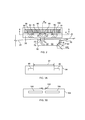
- FIG. 1 is a forward-looking upper perspective view of an exemplary embodiment of a work vehicle including an HVAC system of the present disclosure
- FIG. 2 is a cross-section taken along line 2-2 of FIG. 1 of the present disclosure
- FIG. 3A is a further exemplary embodiment of a forward looking view taken along line 3-3 of FIG. 2 of the present disclosure
- FIG. 3B is a further exemplary embodiment of a forward looking view taken along line 3-3 of FIG. 2 of the present disclosure
- FIG. 4 is an exemplary embodiment of a forward looking view taken along line 4-4 of FIG. 2 of the present disclosure.
- FIG. 5 is a cross-section taken along line 5-5 of FIG. 2 of the present disclosure.
- FIG. 1 shows a work vehicle 10 provided with a frame 12 that rotatably carries a driving device 14, such as a plurality of wheels, although in another embodiment, tracks may be used or activated to selectably move the vehicle.
- a lifting structure 16 includes an arrangement of structural members and actuators controllable by an operator (not shown) to manipulate an implement 18 to perform work.
- Frame 12 structurally supports an operator cab 20 or cab to surround and protect the operator, which frame 12 includes a front end 22 facing implement 18 and an opposed back end 24 with ends 22, 24 positioned between opposed lateral sides 26, 28 of the frame.
- Compartment 32 includes panels 34, 36, with a screened openings 38 formed in panel 36 as an intake for a first source of moving air 40, such as a fan or blower for cooling components contained in compartment 32.
- an HVAC system 48 includes a first chamber 50 positioned at least partially exterior of operator cab 20 beneath a rear window 52 of the operator cab.
- HVAC system 48 includes an inlet 54 for receiving a flow of ambient air 56 from exterior of operator cab 20.
- An arrangement of louvers 58 positioned over inlet 54 results in a first change of direction 60 of the direction of flow of ambient air 56.
- inlet 54 is located opposite exhaust pipe 46 to minimize operator exposure to exhaust discharged from the exhaust pipe 46.
- the arrangement of the exhaust pipe can be different, and therefore, not limit the position of inlet 54 to one side of first chamber 50.
- inlet 54 of first chamber 50 by virtue of the proximity between inlet 54 of first chamber 50 and screened openings 38, with screened openings 38 receiving a significantly greater airflow velocity and pressure than through inlet 54 during operation of the work vehicle, a flow separation occurs between inlet 54 and screened openings 38.
- a reason for the significantly greater airflow velocity and pressure through screened openings 38 than through inlet 54 is due to the first source of moving air 40 operating to draw significantly more airflow through compartment 32 than would be required by a second source of moving air 62 (FIG. 4) that provides airflow to HVAC system 48.
- the airflow through inlet 54 contains less particulate matter and particulate matter of a smaller size than the airflow through screened openings 38.
- particulate matter and particulate matter of a smaller size or particles may include solid and/or liquid components.
- airflow 56 of ambient air passes through inlet 54 and enters first chamber 50.
- airflow 56 experiences a first air pressure reduction 64 and a first reduction in airflow velocity 66 while airflow 56 is still inside first chamber 50.
- the first air pressure reduction 64 and the first reduction in airflow velocity 66 is sufficient to reduce an amount of particles 68 entrained in the airflow 56 while the particles 68 are within the first chamber 50.
- An aperture 70 formed in first chamber 50 permits particles 68 no longer entrained in airflow 56 to exit first chamber 50.
- aperture 70 is positioned at or near a low or lowest location of first chamber 50, permitting particles 68 to exit first chamber 50 as a result of gravitational forces urging the particles toward and then through aperture 70.
- first chamber 50 is removable from exterior of operator cab 20. In a further embodiment, substantially all liquid particles have been removed from the airflow of ambient air prior to the airflow exiting the first chamber 50.
- airflow 56 of ambient air having a reduced number of entrained particles passes through an outlet 72 formed in first chamber 50, through a conduit 74 interconnecting outlet 72 of first chamber 50 and an inlet 76 of the second chamber 78, then through the inlet 76 of the second chamber 78 and entering the second chamber.
- airflow 56 is subjected to a second change of direction 80 which bifurcates airflow 56 prior to airflow 56 striking the wall 84 of the second chamber 78.
- second change of direction 80 represents about a 90 degree turn, although in other embodiments, the magnitude of the turn of airflow 56 may be greater than or less than 90 degrees.
- an exemplary embodiment of wall 84 includes a spacing 92 or distance separating outlets 86 formed in wall 84.
- a spacing 192 separating outlets 186 formed in wall 184 is less than spacing 92 formed in wall 84.
- spacing 192 results in the formation of a boundary layer in three dimensions prior to the airflow achieving third change of direction 82, resulting in turbulence associated with the airflow and a desirable noise reduction as perceived by the operator.
- the size and shapes of both openings and spacings formed in the wall of the second chamber may vary, depending upon conditions associated with operation of the work vehicle. While third change of direction 82 of airflow 56 occurs between second chamber 78 and third chamber 88, since the third change of direction 82 is considered to begin occurring while the airflow 56 is still in second chamber 78. Therefore, the third change of direction 82 is also considered to occur while the airflow 56 is still in second chamber 78.
- the second chamber may be configured such that more than two changes of direction may occur in the second chamber. Such changes in direction of the airflow result in a reduction of operating noise as perceived by the operator.
- Re-circulated air 100 may be selectably brought into thermal heat exchange with one or more heat exchangers 108 of the HVAC system by selective control of the operator, to maintain a comfortable environment (temperature and humidity control) within operator cab 20.
- the combined or mixed airflow 102 is directed through a filter 104 prior to circulation in operator cab 20 by second source of moving air 62.
- filter 104 is positioned beneath third chamber 88, the filter may be arranged differently in other embodiments.
- opening 90 may include a number of louvers 106 that are directed away from the operator.
- the louver direction is facing aft of the operator.
- the second chamber and the third chamber may be formed from a single housing or structure. Stated another way, the second chamber and the third chamber may define housing having a unitary construction.
Landscapes
- Engineering & Computer Science (AREA)
- Mechanical Engineering (AREA)
- Physics & Mathematics (AREA)
- Thermal Sciences (AREA)
- Air-Conditioning For Vehicles (AREA)
Abstract
L'invention porte sur un système HVAC (48) pour un véhicule de chantier (10) ayant une cabine de conducteur (20), lequel système comprend une première chambre (50) ayant une entrée (54) destinée à recevoir un flux d'air (56) extérieur à la cabine. L'entrée est adjacente à une première source d'air en mouvement (40) destinée à être utilisée indépendamment du système HVAC, l'entrée étant agencée pour provoquer un premier changement de direction (60) du flux d'air à l'intérieur de la première chambre. La première chambre ayant pour effet une première réduction de la pression d'air (64) et une première réduction de la vitesse du flux d'air (66) pendant qu'il se trouve à l'intérieur de la première chambre, qui sont suffisantes pour réduire une quantité de particules (68) entraînées dans le flux d'air pendant que les particules sont dans la première chambre. Une deuxième chambre (78) est en communication fluidique avec la première chambre et est conçue pour provoquer à la fois un deuxième changement de direction (80) et un troisième changement de direction (82) du flux d'air pendant qu'il se trouve à l'intérieur de la deuxième chambre avant qu'il n'atteigne une troisième chambre (88) destinée à mélanger le flux d'air avec l'air remis en circulation en provenance de la cabine.
Priority Applications (1)
| Application Number | Priority Date | Filing Date | Title |
|---|---|---|---|
| EP12705237.1A EP2673151B1 (fr) | 2011-02-11 | 2012-02-09 | Système hvac pour véhicule de chantier |
Applications Claiming Priority (12)
| Application Number | Priority Date | Filing Date | Title |
|---|---|---|---|
| US201161463112P | 2011-02-11 | 2011-02-11 | |
| US201161463059P | 2011-02-11 | 2011-02-11 | |
| US201161463061P | 2011-02-11 | 2011-02-11 | |
| US61/463,059 | 2011-02-11 | ||
| US61/463,112 | 2011-02-11 | ||
| US61/463,061 | 2011-02-11 | ||
| US13/116,050 | 2011-05-26 | ||
| US13/116,495 US8561740B2 (en) | 2011-02-11 | 2011-05-26 | HVAC system for a work vehicle |
| US13/116,495 | 2011-05-26 | ||
| US13/116,050 US20120205946A1 (en) | 2011-02-11 | 2011-05-26 | Hvac system for a work vehicle |
| US13/220,250 US20120208446A1 (en) | 2011-02-11 | 2011-08-29 | Hvac system for a work vehicle |
| US13/220,250 | 2011-08-29 |
Publications (1)
| Publication Number | Publication Date |
|---|---|
| WO2012107512A1 true WO2012107512A1 (fr) | 2012-08-16 |
Family
ID=46637246
Family Applications (2)
| Application Number | Title | Priority Date | Filing Date |
|---|---|---|---|
| PCT/EP2012/052215 Ceased WO2012107521A1 (fr) | 2011-02-11 | 2012-02-09 | Système de chauffage, de ventilation et de conditionnement d'air (hvac) pour un véhicule de travail |
| PCT/EP2012/052175 Ceased WO2012107512A1 (fr) | 2011-02-11 | 2012-02-09 | Système hvac pour véhicule de chantier |
Family Applications Before (1)
| Application Number | Title | Priority Date | Filing Date |
|---|---|---|---|
| PCT/EP2012/052215 Ceased WO2012107521A1 (fr) | 2011-02-11 | 2012-02-09 | Système de chauffage, de ventilation et de conditionnement d'air (hvac) pour un véhicule de travail |
Country Status (3)
| Country | Link |
|---|---|
| US (1) | US20120208446A1 (fr) |
| EP (2) | EP2673151B1 (fr) |
| WO (2) | WO2012107521A1 (fr) |
Families Citing this family (6)
| Publication number | Priority date | Publication date | Assignee | Title |
|---|---|---|---|---|
| US9963014B2 (en) * | 2016-01-15 | 2018-05-08 | Joy Mm Delaware, Inc. | Debris barrier for vehicle operator cab |
| CN108602539B (zh) | 2016-02-05 | 2021-12-10 | 克拉克设备公司 | 履带式多功能车辆 |
| US10543733B2 (en) * | 2016-11-14 | 2020-01-28 | Cnh Industrial America Llc | Heating, ventilation, and air conditioning system of a work vehicle |
| US10190286B2 (en) * | 2017-03-20 | 2019-01-29 | Deere & Company | Debris deflection apparatus for operators station cleanout |
| CA3130402A1 (fr) | 2019-02-22 | 2020-08-27 | Clark Equipment Company | Systeme de ventilation pour une machine generatrice d'energie |
| US11648825B2 (en) * | 2020-06-22 | 2023-05-16 | Caterpillar Inc. | Screen assembly for construction vehicle |
Citations (6)
| Publication number | Priority date | Publication date | Assignee | Title |
|---|---|---|---|---|
| US2011840A (en) | 1933-04-05 | 1935-08-20 | Gen Motors Corp | Rainproof cowl ventilator |
| US2685244A (en) | 1950-02-25 | 1954-08-03 | Nash Kelvinator Corp | Air conditioning system |
| US2852997A (en) | 1954-09-09 | 1958-09-23 | Gen Motors Corp | Vehicle ventilation system using shroud chambers |
| WO1982002086A1 (fr) * | 1980-12-12 | 1982-06-24 | Marques Jerry G | Dispositif de filtration pour un systeme de circulation d'air |
| US4597323A (en) | 1983-08-27 | 1986-07-01 | Daimler-Benz Aktiengesellschaft | Vehicle air conditioning installation |
| DE3813548A1 (de) * | 1988-04-22 | 1989-11-09 | Daimler Benz Ag | Belueftungseinrichtung, insbesondere heiz- oder klimaanlage, fuer den innenraum eines fahrzeuges, insbesondere kraftfahrzeuge |
Family Cites Families (27)
| Publication number | Priority date | Publication date | Assignee | Title |
|---|---|---|---|---|
| US1485324A (en) * | 1919-03-21 | 1924-02-26 | Yerly Arthur | Rolling window screen |
| US1879534A (en) * | 1930-03-04 | 1932-09-27 | Schmidt Sheet Metal Works Inc | Window screen |
| US2072726A (en) * | 1936-03-18 | 1937-03-02 | Yartyan Minas | Latch |
| US2188050A (en) * | 1936-10-15 | 1940-01-23 | Rolsereen Company | Window structure |
| US2150851A (en) * | 1937-12-13 | 1939-03-14 | Thompson Foster John | Casement window fastener |
| US2247306A (en) * | 1940-02-02 | 1941-06-24 | Harry C Partridge | Screen retainer |
| US2665753A (en) * | 1950-04-17 | 1954-01-12 | Lang Albert | Screen holding strip securing means |
| US2761291A (en) * | 1954-06-09 | 1956-09-04 | Studebaker Packard Corp | Air duct for automobile cooling system |
| US3102579A (en) * | 1961-12-07 | 1963-09-03 | Elwin E Burton | Storm window and screen retaining strip |
| US3366159A (en) * | 1965-12-07 | 1968-01-30 | Rolscreen Co | Venetian blind operating means |
| US3423908A (en) * | 1966-06-16 | 1969-01-28 | Cambridge Filter Corp | Side-loading filter housing |
| US3555846A (en) * | 1968-12-13 | 1971-01-19 | Stolper Ind Inc | Air-conditioned vehicle cab |
| US4048911A (en) | 1976-07-29 | 1977-09-20 | Petersen Ross K | Air supply apparatus |
| US4120527A (en) | 1977-04-15 | 1978-10-17 | Caterpillar Tractor Co. | Cab design |
| US4365411A (en) | 1980-08-28 | 1982-12-28 | Bivar, Inc. | Method and means for insertion of inserts into a hole of a predrilled board |
| US4531453A (en) * | 1983-05-16 | 1985-07-30 | Deere & Company | Atmosphere control arrangement for an operator enclosure |
| US4612975A (en) * | 1984-02-07 | 1986-09-23 | Kabushiki Kaisha Komatsu Seisakusho | Air conditioning device installed in a cabin of an earth-moving vehicle |
| US4660462A (en) * | 1985-08-12 | 1987-04-28 | Deere & Company | Ventilation system and filter |
| US5308279A (en) * | 1991-10-28 | 1994-05-03 | Caterpillar Inc. | Air circulatory system for an enclosure |
| US6223807B1 (en) * | 1999-07-09 | 2001-05-01 | Clark Equipment Company | Heating, ventilating and air conditioning system for a skid steer loader |
| US20030073400A1 (en) * | 2001-10-12 | 2003-04-17 | Dahl Jeffrey A. | Wheeled work machine with modular ventilation system |
| US6692551B2 (en) * | 2002-07-17 | 2004-02-17 | Delphi Technologies, Inc. | Air cleaner assembly and process |
| US7377848B2 (en) * | 2006-07-12 | 2008-05-27 | Cnh America Llc | Filter purge control for HVAC variable air circulation system |
| US20080163634A1 (en) * | 2007-01-09 | 2008-07-10 | Denso Corporation | Air conditioning system for construction and agricultural vehicles |
| US8430450B2 (en) * | 2008-08-20 | 2013-04-30 | Deere & Company | Work machine with door-mountable fresh air filter |
| GB2464726A (en) * | 2008-10-27 | 2010-04-28 | Agco Gmbh | Tractor cab air filter housing with integral access door storage compartment |
| GB2466765A (en) * | 2008-10-27 | 2010-07-07 | Agco Gmbh | Tractor HVAC system ducting and air filter arrangement |
-
2011
- 2011-08-29 US US13/220,250 patent/US20120208446A1/en not_active Abandoned
-
2012
- 2012-02-09 WO PCT/EP2012/052215 patent/WO2012107521A1/fr not_active Ceased
- 2012-02-09 EP EP12705237.1A patent/EP2673151B1/fr active Active
- 2012-02-09 WO PCT/EP2012/052175 patent/WO2012107512A1/fr not_active Ceased
- 2012-02-09 EP EP12705239.7A patent/EP2673152B1/fr active Active
Patent Citations (6)
| Publication number | Priority date | Publication date | Assignee | Title |
|---|---|---|---|---|
| US2011840A (en) | 1933-04-05 | 1935-08-20 | Gen Motors Corp | Rainproof cowl ventilator |
| US2685244A (en) | 1950-02-25 | 1954-08-03 | Nash Kelvinator Corp | Air conditioning system |
| US2852997A (en) | 1954-09-09 | 1958-09-23 | Gen Motors Corp | Vehicle ventilation system using shroud chambers |
| WO1982002086A1 (fr) * | 1980-12-12 | 1982-06-24 | Marques Jerry G | Dispositif de filtration pour un systeme de circulation d'air |
| US4597323A (en) | 1983-08-27 | 1986-07-01 | Daimler-Benz Aktiengesellschaft | Vehicle air conditioning installation |
| DE3813548A1 (de) * | 1988-04-22 | 1989-11-09 | Daimler Benz Ag | Belueftungseinrichtung, insbesondere heiz- oder klimaanlage, fuer den innenraum eines fahrzeuges, insbesondere kraftfahrzeuge |
Also Published As
| Publication number | Publication date |
|---|---|
| EP2673152B1 (fr) | 2016-12-07 |
| EP2673151A1 (fr) | 2013-12-18 |
| EP2673152A1 (fr) | 2013-12-18 |
| WO2012107521A1 (fr) | 2012-08-16 |
| EP2673151B1 (fr) | 2017-06-21 |
| US20120208446A1 (en) | 2012-08-16 |
Similar Documents
| Publication | Publication Date | Title |
|---|---|---|
| EP2673151B1 (fr) | Système hvac pour véhicule de chantier | |
| CN103764425B (zh) | 隔板上方进气系统 | |
| CN102958721B (zh) | 安装有hvac系统的农用车辆驾驶室 | |
| EP2480425B1 (fr) | Système de ventilation d'air naturel pour un habitacle de véhicule | |
| JP5449313B2 (ja) | 自動車用隔壁上吸気システム | |
| US20200079175A1 (en) | Cab with fresh air path through the posts | |
| JP5704032B2 (ja) | 車両用空調装置 | |
| US12017514B2 (en) | HVAC air retrieval system for work machine | |
| US8561740B2 (en) | HVAC system for a work vehicle | |
| SE512436C2 (sv) | Klimatanläggning för fordon | |
| KR20140145003A (ko) | 공조장치를 탑재한 작업차용 캐빈 | |
| US9186981B2 (en) | Work vehicle | |
| CN204623060U (zh) | 空调组件、具有空调组件的驾驶室及拖拉机和联合收割机 | |
| US11092065B2 (en) | Engine air precleaner system | |
| CN200996157Y (zh) | 用于工程机械车辆的驾驶室及包括其的车辆 | |
| CN120716416A (zh) | 外部空气引入装置和包括该装置的车辆hvac系统 | |
| JPH0577641A (ja) | 天井設置型車両用クーリングユニツト | |
| AU2019240585B2 (en) | Filter element and filter assembly having two filtration zones | |
| RU2184039C2 (ru) | Вентиляционное устройство кабины транспортного средства | |
| JP4613722B2 (ja) | 車両用換気システム | |
| RU2044915C1 (ru) | Двигатель внутреннего сгорания транспортного средства | |
| JP6280464B2 (ja) | 作業車両 | |
| JP3027767B2 (ja) | 包囲区域内の空気循環システム | |
| JPH09328014A (ja) | 作業車の空調装置 |
Legal Events
| Date | Code | Title | Description |
|---|---|---|---|
| 121 | Ep: the epo has been informed by wipo that ep was designated in this application |
Ref document number: 12705237 Country of ref document: EP Kind code of ref document: A1 |
|
| NENP | Non-entry into the national phase |
Ref country code: DE |
|
| REEP | Request for entry into the european phase |
Ref document number: 2012705237 Country of ref document: EP |
|
| WWE | Wipo information: entry into national phase |
Ref document number: 2012705237 Country of ref document: EP |