WO2012108000A1 - Dispositif de logement de câble et véhicule - Google Patents
Dispositif de logement de câble et véhicule Download PDFInfo
- Publication number
- WO2012108000A1 WO2012108000A1 PCT/JP2011/052640 JP2011052640W WO2012108000A1 WO 2012108000 A1 WO2012108000 A1 WO 2012108000A1 JP 2011052640 W JP2011052640 W JP 2011052640W WO 2012108000 A1 WO2012108000 A1 WO 2012108000A1
- Authority
- WO
- WIPO (PCT)
- Prior art keywords
- cable
- core wire
- power
- housing device
- vehicle
- Prior art date
- Legal status (The legal status is an assumption and is not a legal conclusion. Google has not performed a legal analysis and makes no representation as to the accuracy of the status listed.)
- Ceased
Links
Images

Classifications
-
- H—ELECTRICITY
- H02—GENERATION; CONVERSION OR DISTRIBUTION OF ELECTRIC POWER
- H02G—INSTALLATION OF ELECTRIC CABLES OR LINES, OR OF COMBINED OPTICAL AND ELECTRIC CABLES OR LINES
- H02G11/00—Arrangements of electric cables or lines between relatively-movable parts
- H02G11/02—Arrangements of electric cables or lines between relatively-movable parts using take-up reel or drum
-
- B—PERFORMING OPERATIONS; TRANSPORTING
- B60—VEHICLES IN GENERAL
- B60L—PROPULSION OF ELECTRICALLY-PROPELLED VEHICLES; SUPPLYING ELECTRIC POWER FOR AUXILIARY EQUIPMENT OF ELECTRICALLY-PROPELLED VEHICLES; ELECTRODYNAMIC BRAKE SYSTEMS FOR VEHICLES IN GENERAL; MAGNETIC SUSPENSION OR LEVITATION FOR VEHICLES; MONITORING OPERATING VARIABLES OF ELECTRICALLY-PROPELLED VEHICLES; ELECTRIC SAFETY DEVICES FOR ELECTRICALLY-PROPELLED VEHICLES
- B60L50/00—Electric propulsion with power supplied within the vehicle
- B60L50/10—Electric propulsion with power supplied within the vehicle using propulsion power supplied by engine-driven generators, e.g. generators driven by combustion engines
- B60L50/16—Electric propulsion with power supplied within the vehicle using propulsion power supplied by engine-driven generators, e.g. generators driven by combustion engines with provision for separate direct mechanical propulsion
-
- B—PERFORMING OPERATIONS; TRANSPORTING
- B60—VEHICLES IN GENERAL
- B60L—PROPULSION OF ELECTRICALLY-PROPELLED VEHICLES; SUPPLYING ELECTRIC POWER FOR AUXILIARY EQUIPMENT OF ELECTRICALLY-PROPELLED VEHICLES; ELECTRODYNAMIC BRAKE SYSTEMS FOR VEHICLES IN GENERAL; MAGNETIC SUSPENSION OR LEVITATION FOR VEHICLES; MONITORING OPERATING VARIABLES OF ELECTRICALLY-PROPELLED VEHICLES; ELECTRIC SAFETY DEVICES FOR ELECTRICALLY-PROPELLED VEHICLES
- B60L50/00—Electric propulsion with power supplied within the vehicle
- B60L50/50—Electric propulsion with power supplied within the vehicle using propulsion power supplied by batteries or fuel cells
- B60L50/60—Electric propulsion with power supplied within the vehicle using propulsion power supplied by batteries or fuel cells using power supplied by batteries
- B60L50/61—Electric propulsion with power supplied within the vehicle using propulsion power supplied by batteries or fuel cells using power supplied by batteries by batteries charged by engine-driven generators, e.g. series hybrid electric vehicles
-
- B—PERFORMING OPERATIONS; TRANSPORTING
- B60—VEHICLES IN GENERAL
- B60L—PROPULSION OF ELECTRICALLY-PROPELLED VEHICLES; SUPPLYING ELECTRIC POWER FOR AUXILIARY EQUIPMENT OF ELECTRICALLY-PROPELLED VEHICLES; ELECTRODYNAMIC BRAKE SYSTEMS FOR VEHICLES IN GENERAL; MAGNETIC SUSPENSION OR LEVITATION FOR VEHICLES; MONITORING OPERATING VARIABLES OF ELECTRICALLY-PROPELLED VEHICLES; ELECTRIC SAFETY DEVICES FOR ELECTRICALLY-PROPELLED VEHICLES
- B60L50/00—Electric propulsion with power supplied within the vehicle
- B60L50/50—Electric propulsion with power supplied within the vehicle using propulsion power supplied by batteries or fuel cells
- B60L50/60—Electric propulsion with power supplied within the vehicle using propulsion power supplied by batteries or fuel cells using power supplied by batteries
- B60L50/66—Arrangements of batteries
-
- B—PERFORMING OPERATIONS; TRANSPORTING
- B60—VEHICLES IN GENERAL
- B60L—PROPULSION OF ELECTRICALLY-PROPELLED VEHICLES; SUPPLYING ELECTRIC POWER FOR AUXILIARY EQUIPMENT OF ELECTRICALLY-PROPELLED VEHICLES; ELECTRODYNAMIC BRAKE SYSTEMS FOR VEHICLES IN GENERAL; MAGNETIC SUSPENSION OR LEVITATION FOR VEHICLES; MONITORING OPERATING VARIABLES OF ELECTRICALLY-PROPELLED VEHICLES; ELECTRIC SAFETY DEVICES FOR ELECTRICALLY-PROPELLED VEHICLES
- B60L53/00—Methods of charging batteries, specially adapted for electric vehicles; Charging stations or on-board charging equipment therefor; Exchange of energy storage elements in electric vehicles
- B60L53/10—Methods of charging batteries, specially adapted for electric vehicles; Charging stations or on-board charging equipment therefor; Exchange of energy storage elements in electric vehicles characterised by the energy transfer between the charging station and the vehicle
- B60L53/14—Conductive energy transfer
- B60L53/16—Connectors, e.g. plugs or sockets, specially adapted for charging electric vehicles
-
- B—PERFORMING OPERATIONS; TRANSPORTING
- B60—VEHICLES IN GENERAL
- B60L—PROPULSION OF ELECTRICALLY-PROPELLED VEHICLES; SUPPLYING ELECTRIC POWER FOR AUXILIARY EQUIPMENT OF ELECTRICALLY-PROPELLED VEHICLES; ELECTRODYNAMIC BRAKE SYSTEMS FOR VEHICLES IN GENERAL; MAGNETIC SUSPENSION OR LEVITATION FOR VEHICLES; MONITORING OPERATING VARIABLES OF ELECTRICALLY-PROPELLED VEHICLES; ELECTRIC SAFETY DEVICES FOR ELECTRICALLY-PROPELLED VEHICLES
- B60L53/00—Methods of charging batteries, specially adapted for electric vehicles; Charging stations or on-board charging equipment therefor; Exchange of energy storage elements in electric vehicles
- B60L53/10—Methods of charging batteries, specially adapted for electric vehicles; Charging stations or on-board charging equipment therefor; Exchange of energy storage elements in electric vehicles characterised by the energy transfer between the charging station and the vehicle
- B60L53/14—Conductive energy transfer
- B60L53/18—Cables specially adapted for charging electric vehicles
-
- B—PERFORMING OPERATIONS; TRANSPORTING
- B60—VEHICLES IN GENERAL
- B60L—PROPULSION OF ELECTRICALLY-PROPELLED VEHICLES; SUPPLYING ELECTRIC POWER FOR AUXILIARY EQUIPMENT OF ELECTRICALLY-PROPELLED VEHICLES; ELECTRODYNAMIC BRAKE SYSTEMS FOR VEHICLES IN GENERAL; MAGNETIC SUSPENSION OR LEVITATION FOR VEHICLES; MONITORING OPERATING VARIABLES OF ELECTRICALLY-PROPELLED VEHICLES; ELECTRIC SAFETY DEVICES FOR ELECTRICALLY-PROPELLED VEHICLES
- B60L7/00—Electrodynamic brake systems for vehicles in general
- B60L7/10—Dynamic electric regenerative braking
- B60L7/14—Dynamic electric regenerative braking for vehicles propelled by AC motors
-
- B—PERFORMING OPERATIONS; TRANSPORTING
- B60—VEHICLES IN GENERAL
- B60L—PROPULSION OF ELECTRICALLY-PROPELLED VEHICLES; SUPPLYING ELECTRIC POWER FOR AUXILIARY EQUIPMENT OF ELECTRICALLY-PROPELLED VEHICLES; ELECTRODYNAMIC BRAKE SYSTEMS FOR VEHICLES IN GENERAL; MAGNETIC SUSPENSION OR LEVITATION FOR VEHICLES; MONITORING OPERATING VARIABLES OF ELECTRICALLY-PROPELLED VEHICLES; ELECTRIC SAFETY DEVICES FOR ELECTRICALLY-PROPELLED VEHICLES
- B60L2210/00—Converter types
- B60L2210/10—DC to DC converters
-
- B—PERFORMING OPERATIONS; TRANSPORTING
- B60—VEHICLES IN GENERAL
- B60L—PROPULSION OF ELECTRICALLY-PROPELLED VEHICLES; SUPPLYING ELECTRIC POWER FOR AUXILIARY EQUIPMENT OF ELECTRICALLY-PROPELLED VEHICLES; ELECTRODYNAMIC BRAKE SYSTEMS FOR VEHICLES IN GENERAL; MAGNETIC SUSPENSION OR LEVITATION FOR VEHICLES; MONITORING OPERATING VARIABLES OF ELECTRICALLY-PROPELLED VEHICLES; ELECTRIC SAFETY DEVICES FOR ELECTRICALLY-PROPELLED VEHICLES
- B60L2210/00—Converter types
- B60L2210/30—AC to DC converters
-
- B—PERFORMING OPERATIONS; TRANSPORTING
- B60—VEHICLES IN GENERAL
- B60L—PROPULSION OF ELECTRICALLY-PROPELLED VEHICLES; SUPPLYING ELECTRIC POWER FOR AUXILIARY EQUIPMENT OF ELECTRICALLY-PROPELLED VEHICLES; ELECTRODYNAMIC BRAKE SYSTEMS FOR VEHICLES IN GENERAL; MAGNETIC SUSPENSION OR LEVITATION FOR VEHICLES; MONITORING OPERATING VARIABLES OF ELECTRICALLY-PROPELLED VEHICLES; ELECTRIC SAFETY DEVICES FOR ELECTRICALLY-PROPELLED VEHICLES
- B60L2210/00—Converter types
- B60L2210/40—DC to AC converters
-
- B—PERFORMING OPERATIONS; TRANSPORTING
- B60—VEHICLES IN GENERAL
- B60L—PROPULSION OF ELECTRICALLY-PROPELLED VEHICLES; SUPPLYING ELECTRIC POWER FOR AUXILIARY EQUIPMENT OF ELECTRICALLY-PROPELLED VEHICLES; ELECTRODYNAMIC BRAKE SYSTEMS FOR VEHICLES IN GENERAL; MAGNETIC SUSPENSION OR LEVITATION FOR VEHICLES; MONITORING OPERATING VARIABLES OF ELECTRICALLY-PROPELLED VEHICLES; ELECTRIC SAFETY DEVICES FOR ELECTRICALLY-PROPELLED VEHICLES
- B60L2220/00—Electrical machine types; Structures or applications thereof
- B60L2220/10—Electrical machine types
- B60L2220/14—Synchronous machines
-
- B—PERFORMING OPERATIONS; TRANSPORTING
- B60—VEHICLES IN GENERAL
- B60L—PROPULSION OF ELECTRICALLY-PROPELLED VEHICLES; SUPPLYING ELECTRIC POWER FOR AUXILIARY EQUIPMENT OF ELECTRICALLY-PROPELLED VEHICLES; ELECTRODYNAMIC BRAKE SYSTEMS FOR VEHICLES IN GENERAL; MAGNETIC SUSPENSION OR LEVITATION FOR VEHICLES; MONITORING OPERATING VARIABLES OF ELECTRICALLY-PROPELLED VEHICLES; ELECTRIC SAFETY DEVICES FOR ELECTRICALLY-PROPELLED VEHICLES
- B60L2240/00—Control parameters of input or output; Target parameters
- B60L2240/10—Vehicle control parameters
- B60L2240/36—Temperature of vehicle components or parts
-
- Y—GENERAL TAGGING OF NEW TECHNOLOGICAL DEVELOPMENTS; GENERAL TAGGING OF CROSS-SECTIONAL TECHNOLOGIES SPANNING OVER SEVERAL SECTIONS OF THE IPC; TECHNICAL SUBJECTS COVERED BY FORMER USPC CROSS-REFERENCE ART COLLECTIONS [XRACs] AND DIGESTS
- Y02—TECHNOLOGIES OR APPLICATIONS FOR MITIGATION OR ADAPTATION AGAINST CLIMATE CHANGE
- Y02T—CLIMATE CHANGE MITIGATION TECHNOLOGIES RELATED TO TRANSPORTATION
- Y02T10/00—Road transport of goods or passengers
- Y02T10/60—Other road transportation technologies with climate change mitigation effect
- Y02T10/62—Hybrid vehicles
-
- Y—GENERAL TAGGING OF NEW TECHNOLOGICAL DEVELOPMENTS; GENERAL TAGGING OF CROSS-SECTIONAL TECHNOLOGIES SPANNING OVER SEVERAL SECTIONS OF THE IPC; TECHNICAL SUBJECTS COVERED BY FORMER USPC CROSS-REFERENCE ART COLLECTIONS [XRACs] AND DIGESTS
- Y02—TECHNOLOGIES OR APPLICATIONS FOR MITIGATION OR ADAPTATION AGAINST CLIMATE CHANGE
- Y02T—CLIMATE CHANGE MITIGATION TECHNOLOGIES RELATED TO TRANSPORTATION
- Y02T10/00—Road transport of goods or passengers
- Y02T10/60—Other road transportation technologies with climate change mitigation effect
- Y02T10/70—Energy storage systems for electromobility, e.g. batteries
-
- Y—GENERAL TAGGING OF NEW TECHNOLOGICAL DEVELOPMENTS; GENERAL TAGGING OF CROSS-SECTIONAL TECHNOLOGIES SPANNING OVER SEVERAL SECTIONS OF THE IPC; TECHNICAL SUBJECTS COVERED BY FORMER USPC CROSS-REFERENCE ART COLLECTIONS [XRACs] AND DIGESTS
- Y02—TECHNOLOGIES OR APPLICATIONS FOR MITIGATION OR ADAPTATION AGAINST CLIMATE CHANGE
- Y02T—CLIMATE CHANGE MITIGATION TECHNOLOGIES RELATED TO TRANSPORTATION
- Y02T10/00—Road transport of goods or passengers
- Y02T10/60—Other road transportation technologies with climate change mitigation effect
- Y02T10/7072—Electromobility specific charging systems or methods for batteries, ultracapacitors, supercapacitors or double-layer capacitors
-
- Y—GENERAL TAGGING OF NEW TECHNOLOGICAL DEVELOPMENTS; GENERAL TAGGING OF CROSS-SECTIONAL TECHNOLOGIES SPANNING OVER SEVERAL SECTIONS OF THE IPC; TECHNICAL SUBJECTS COVERED BY FORMER USPC CROSS-REFERENCE ART COLLECTIONS [XRACs] AND DIGESTS
- Y02—TECHNOLOGIES OR APPLICATIONS FOR MITIGATION OR ADAPTATION AGAINST CLIMATE CHANGE
- Y02T—CLIMATE CHANGE MITIGATION TECHNOLOGIES RELATED TO TRANSPORTATION
- Y02T10/00—Road transport of goods or passengers
- Y02T10/60—Other road transportation technologies with climate change mitigation effect
- Y02T10/72—Electric energy management in electromobility
-
- Y—GENERAL TAGGING OF NEW TECHNOLOGICAL DEVELOPMENTS; GENERAL TAGGING OF CROSS-SECTIONAL TECHNOLOGIES SPANNING OVER SEVERAL SECTIONS OF THE IPC; TECHNICAL SUBJECTS COVERED BY FORMER USPC CROSS-REFERENCE ART COLLECTIONS [XRACs] AND DIGESTS
- Y02—TECHNOLOGIES OR APPLICATIONS FOR MITIGATION OR ADAPTATION AGAINST CLIMATE CHANGE
- Y02T—CLIMATE CHANGE MITIGATION TECHNOLOGIES RELATED TO TRANSPORTATION
- Y02T90/00—Enabling technologies or technologies with a potential or indirect contribution to GHG emissions mitigation
- Y02T90/10—Technologies relating to charging of electric vehicles
- Y02T90/14—Plug-in electric vehicles
Definitions
- the present invention relates to a cable housing device and a vehicle equipped with the cable housing device.
- an electric vehicle capable of charging a battery with electric power has been attracting attention in consideration of the environment.
- an externally chargeable electric vehicle when charging the battery, it is conceivable to charge the battery by connecting an external power source provided outside the vehicle and the electric vehicle with a cable.
- a cord reel is generally known as a device for accommodating a cable, and various types of cables and cord reels that can accommodate a long cable in a compact manner have been proposed.
- a video transmission cable described in Japanese Patent Application Laid-Open No. 2003-242839 includes a plurality of twisted wire cores and a coaxial cable, and the plurality of twisted wire cores and the coaxial cable are alternately arranged in parallel,
- the transmission cable is formed into a flat shape.
- a plurality of twisted wire cores are arranged at intervals, and a coaxial cable is placed between each twisted wire core.
- the coaxial cable includes an inner conductor and a plurality of outer conductors arranged so as to surround the inner conductor.
- This invention is made
- the objective is to provide the cable housing device by which the improvement of the thermal radiation efficiency of the cable was achieved, and the vehicle provided with this cable housing device. is there.
- the cable housing device has a cable including a plurality of core wires arranged in one direction and an insulating member covering the plurality of core wires, an outer peripheral surface, and the cable is wound and rotated around the outer peripheral surface.
- a rotating shaft provided in a possible manner, and a support member that is provided on the rotating shaft and supports a cable wound around the rotating shaft.
- the plurality of core wires include one or more power core wires and one or more low current core wires through which a current lower than that of the power core wires flows.
- the power core wires are lower than the low current core wires. Is also arranged at a position close to the contact position between the insulating member and the support member.
- the rotation axis is arranged so that the rotation center line of the rotation axis intersects the horizontal plane.
- the support member is provided at an end portion on the lower side of the rotation shaft.
- the rotation shaft is arranged such that the rotation center line extends in the vertical direction.
- the cross-sectional shape of the cable perpendicular to the extending direction of the cable is a flat shape that is long in the one direction.
- the cable housing device further includes a blower that supplies cooling air toward the support member.
- a vehicle according to the present invention includes the cable housing device and a body having a cable outlet through which a cable is drawn out on the back surface.
- the cable housing device and the vehicle according to the present invention it is possible to suppress an increase in the cable temperature.
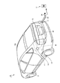
- FIG. 1 is a rear perspective view showing a vehicle according to a first embodiment.
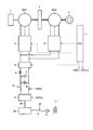
- 1 is a block diagram showing a vehicle 10.
- FIG. 3 is a cross-sectional view of the cable housing device 30.
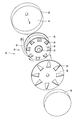
- FIG. 3 is an exploded perspective view of the cable housing device 30.
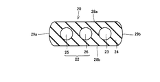
- FIG. 3 is a cross-sectional view of the cable 20.
- a cable housing device and a vehicle according to an embodiment of the present invention will be described with reference to FIGS.
- an example applied to a so-called hybrid vehicle will be described, but it goes without saying that the embodiment can also be applied to an electric vehicle.
- FIG. 1 is a rear perspective view showing the vehicle according to the first embodiment.
- a vehicle 10 includes a body 10a that is an outer shell of the vehicle, a battery B and a fuel tank FT mounted in the vehicle 10, and a cable 20 that is mounted in the vehicle 10 and wound thereon.
- a cable housing device 30 is shown in FIG. 1, a vehicle 10 includes a body 10a that is an outer shell of the vehicle, a battery B and a fuel tank FT mounted in the vehicle 10, and a cable 20 that is mounted in the vehicle 10 and wound thereon.
- a cable housing device 30 is a cable housing device 30.
- the body 10a includes a back surface 12 on which a cable outlet 11 from which the cable 20 is drawn is formed, and a side surface 14 on which an oil supply portion 13 is formed.
- the battery B is a battery capable of storing electric power, and is connected to the cable housing device 30 via a converter or the like which will be described later.
- a secondary battery such as a nickel metal hydride battery, a lithium ion battery, or a lead storage battery can be used.
- a large-capacity electric double layer capacitor can be used in place of the battery B.
- the fuel tank FT is a tank that stores fuel such as gasoline or light oil supplied from the fuel supply unit 13. Fuel tank FT is arranged on the front side of vehicle 10 with respect to battery B.
- the cable housing device 30 includes a cable 20 and a plug 21 provided at the tip of the cable 20.
- the plug 21 can be connected to a power source 17 provided outside the vehicle 10. By connecting the plug 21 to the power source 17, the battery B can be charged with the power from the power source 17.
- the power source 17 is a household power source or a commercial power source provided in a charging facility such as a charging station.
- FIG. 2 is a block diagram showing the vehicle 10.
- the vehicle 10 includes an engine 1, motor generators MG1, MG2, a power split mechanism 2, a battery B, a capacitor C, a reactor L, a converter 4, an inverter 5, an inverter 6, and a vehicle ECU (Electronic Control Unit). ) 7, the switching element 8, the converter 9, and the cable housing device 30.
- the power split mechanism 2 is coupled to the engine 1 and the motor generators MG1 and MG2, and distributes power between them.
- a planetary gear mechanism having three rotating shafts of a sun gear, a planetary carrier, and a ring gear is used. These three rotation shafts are connected to the rotation shafts of engine 1 and motor generators MG1, MG2.
- the rotor of motor generator MG1 is hollow, and the engine 1 and motor generators MG1 and MG2 are mechanically connected to power split mechanism 2 by passing the crankshaft of engine 1 through the center thereof.
- rotation shaft of the motor generator MG2 is coupled to the front wheels 3 as drive wheels by a reduction gear and a differential gear (not shown).
- a power reducer for the rotation shaft of motor generator MG2 may be further incorporated in power split device 2.
- the motor generator MG1 is incorporated in the vehicle 10 so as to operate as a generator driven by the engine 1 and to operate as an electric motor capable of starting the engine 1.
- Motor generator MG2 is incorporated in vehicle 10 as an electric motor that drives front wheels 3 that are drive wheels of vehicle 10.
- Motor generators MG1, MG2 are, for example, three-phase AC synchronous motors.
- Motor generators MG1 and MG2 include a three-phase coil including a U-phase coil, a V-phase coil, and a W-phase coil as a stator coil.
- Motor generator MG1 generates a three-phase AC voltage using the engine output, and outputs the generated three-phase AC voltage to inverter 5. Motor generator MG1 generates a driving force by the three-phase AC voltage received from inverter 6 and starts engine 1.
- Motor generator MG2 generates vehicle driving torque by the three-phase AC voltage received from inverter 6. Motor generator MG2 generates a three-phase AC voltage and outputs it to inverter 6 during regenerative braking of the vehicle.
- Switching element 8 and converter 9 are arranged between battery B and cable housing device 30.
- the converter 9 is connected to the cable housing device 30, and the switching element 8 is disposed between the battery B and the converter 9.
- Switching element 8 connects converter 9 and battery B, or disconnects converter 9 and battery B.
- the switching element 8 is switched ON / OFF by a control signal CNTL1 of the vehicle ECU 7.
- the converter 9 is connected to the cable housing device 30 by the connection wiring 39, converts an alternating current from the power source 17 into a direct current, and supplies the direct current to the battery B.
- converter 9 converts the direct current from battery B into an alternating current and supplies it to cable housing device 30.
- the converter 9 is driven based on a control signal CNTL2 from the vehicle ECU 7.
- the vehicle ECU 7 When charging the battery B, the vehicle ECU 7 turns on the switching element 8 to connect the battery B and the converter 9. Then, the vehicle ECU 7 drives the converter 9 so as to convert AC power supplied from the power source 17 into DC power.
- FIG. 3 is a cross-sectional view of the cable housing device 30, and FIG. 4 is an exploded perspective view of the cable housing device 30.
- vehicle 10 includes a floor panel 50 in which a housing recess 51 is formed, and a floor panel 52 that covers the opening of housing recess 51.
- the floor panel 50 is a member that partitions the vehicle exterior and the vehicle interior, and is disposed on the bottom surface of the body 10a.
- the housing recess 51 is disposed, for example, on the back surface 12 side of a portion located between the rear wheels shown in FIG. 1 or a region located between the rear wheels.
- the housing recess 51 is disposed on the back surface 12 side of the battery B shown in FIG.
- the floor panel 52 forms a floor of a luggage room, for example, and the floor panel 52 is formed so that the opening of the housing recess 51 can be opened and closed.
- the cable housing device 30 is housed in the housing recess 51.
- the cable housing device 30 includes a cable 20, a bobbin 31 in which the cable 20 is housed and a hollow inside, a central shaft 32 that rotatably supports the bobbin 31, a connection device 33 housed in the bobbin 31, An outer body 40 that houses the bobbin 31 and the like, a base 41 that supports the outer body 40, and a blower 42 that is disposed below the outer body 40.
- the cable 20 includes a plurality of power core wires 25, a power core wire 26, and a signal core wire 23 arranged in one direction, and a covering insulating member 24 that covers the plurality of core wires.
- the power core wire 25, the power core wire 26, and the signal core wire 23 are provided so as to be arranged in the vertical direction.
- the power core wire 25 and the power core wire 26 form the power wire 22, and when charging the battery B, the amount of current flowing in the power core wires 25 and 26 is the signal core wire 23.
- the voltage of the current flowing through the power core wires 25 and 26 is larger than the amount of current flowing through the power core wires 25 and 26, and is higher than the voltage of the current flowing through the signal core wire 23.
- the power core 25 is disposed at the lowest position
- the power core 26 is disposed above the power core 25 with an interval
- the signal core 23 is the power. It is arranged above the core wire 26 with a space.
- the cross-sectional shape of the cable 20 in the direction perpendicular to the extending direction of the cable 20 is the power core wire 25.
- the flat shape is long in the arrangement direction in which the power core wire 26 and the signal core wire 23 are arranged.
- the cable 20 includes a main surface 28a and a main surface 28b arranged in the thickness direction, and side surfaces 29a and side surfaces 29b arranged in the width direction of the cable 20, and the areas of the main surfaces 28a and 28b are larger than those of the side surfaces 29a and 29b. Is also getting wider.
- the main surface 28b of the cable 20 positioned on the outer peripheral side is disposed on the main surface 28a of the cable 20 positioned on the inner peripheral side.
- the apparatus 30 can be downsized.
- the bobbin 31 includes a rotating shaft 34 that is formed in a hollow shape with the cable 20 wound around an outer peripheral surface, and a support plate 35 and a support plate 36 that are provided at the end of the rotating shaft 34.
- the rotating shaft 34 is rotatably supported on the center shaft 32 by a bearing 37, and is provided so as to be rotatable about a rotation center line O.
- the rotation axis 34 is arranged so that the rotation center line O intersects the horizontal plane. In the example shown in FIG. 3, the rotation axis 34 is arranged so that the rotation center line O extends in the vertical direction. Yes.
- the support plate 35 is provided at the upper end of the rotating shaft 34.
- the support plate 36 is provided at the lower end of the rotating shaft 34 and is formed so as to protrude from the outer peripheral surface of the rotating shaft 34.
- the support plate 36 supports the side surface 29 a of the cable 20 wound around the rotation shaft 34.
- the cable 20 wound around the rotating shaft 34 is lowered by its own weight, and the side surface 29a of the cable 20 is in contact with the support plate 36.
- the power core wire 25 and the power core wire 25 are disposed closer to the contact position 27 between the support plate 36 and the covering insulating member 24 (cable 20) than the signal core wire 23. Is disposed on the opposite side of the contact position 27 with respect to the power line 22. Specifically, the power core wire 25 is closest to the contact position 27, the power core wire 26 is disposed on the side opposite to the contact position 27 with respect to the power core wire 25, and the signal core wire 23 is It is arranged on the opposite side to the contact position 27 with respect to the core wire 26.
- the amount of current flowing through the power cores 25 and 26 is larger than the amount of current flowing through the signal core 23, and therefore the amount of heat generated by the power cores 25 and 26 is greater than the signal amount.
- the amount of heat generated by the core wire 23 is greater.
- the heat from the power core wire 25 is transmitted to the support plate 36 and radiated to the outside, and the power core wire 26 is also close to the contact position 27. Therefore, the heat from the power core wire 26 is transferred from the support plate 36 to the outside. Heat is dissipated. Thereby, it is suppressed that the temperature of the cable 20 becomes high temperature.
- the support plate 36 is formed with an opening 38 for passing cooling air from the blower 42. For this reason, cooling of the cable 20 is promoted by the cooling air from the blower 42.
- the connection device 33 is a device that connects the terminal end of the cable 20 and the connection wiring 39.
- the connecting device 33 includes a stator 43 that is fixed to the central shaft 32 and a rotor 44 that is rotatably provided on the central shaft 32.
- the stator 43 and the rotor 44 are arranged on the central axis 32 with a space therebetween.
- the rotor 44 includes a plurality of terminals 45 arranged at intervals in the radial direction.
- the terminal 45 is provided on a portion of the surface of the rotor 44 that faces the stator 43.
- the terminal 45 arranged on the innermost diameter side is connected to the power core wire 25.
- a terminal 45 adjacent to the terminal 45 connected to the power core wire 25 is connected to the power core wire 26.
- the power core wire 25 arranged on the outermost diameter side is connected to the signal core wire 23.
- Each terminal 45 is biased toward the stator 43.
- the stator 43 includes a plurality of annular terminals 46 arranged at intervals in the radial direction, and each annular terminal 46 is connected to a connection wiring 39.
- Each annular terminal 46 is formed in an annular shape around the rotation center line O, and each annular terminal 46 is formed in a portion of the surface of the stator 43 facing the rotor 44.
- the annular terminal 46 positioned closest to the inner diameter side is in contact with the terminal 45 connected to the power core wire 25.
- the annular terminal 46 adjacent to the annular terminal 46 is in contact with the terminal 45 to which the power core wire 26 is connected.
- the annular terminal 46 arranged on the outermost diameter side is in contact with a terminal 45 connected to the signal core wire 23. According to this connection device 33, even if the cable 20 is pulled out and the bobbin 31 rotates, the connection state between the power line 22 and the signal core wire 23 and the connection wiring 39 is maintained.
- the outer body 40 includes a top plate portion 47, a bottom wall portion 48, and a peripheral wall portion 49.
- the top plate portion 47 is disposed so as to face the support plate 35
- the bottom wall portion 48 is disposed so as to face the support plate 36.
- the top plate portion 47 fixes one end of the central shaft 32, and the bottom wall portion 48 fixes the other end of the central shaft 32.
- An opening 53 is formed in the bottom wall portion 48, and cooling air from the blower 42 enters the outer body 40 through the opening 53. The cooling air that is stuck in the outer body 40 passes through the opening 38 and cools the cable 20.
- the base 41 supports the bottom wall portion 48 of the outer body 40, and a gap is formed between the bottom wall portion 48 and the bottom surface of the housing recess 51.
- the blower 42 is disposed between the bottom wall portion 48 and the bottom surface of the housing recess 51, and the blower 42 supplies cooling air toward the support plate 36.
- the support plate 36 is cooled by the cooling air from the blower 42, so that the cooling efficiency of the cable 20 is improved.
- blower 42 is provided as a device for cooling the support plate 36 .
- other devices may be employed instead of the blower 42.
- a duct for blowing a part of the cooling air blown from the cooling fan that cools the battery B shown in FIG. 1 to the support plate 36 may be provided.
- FIG. 5 is a cross-sectional view of the cable 20. As shown in FIG. 5, the distance between the side surface 29 a and the power core wire 25 is larger than the distance between the power core wire 25 and the power core wire 26. Similarly, the distance between the side surface 29 b and the signal core wire 23 is larger than the distance between the signal core wire 23 and the power core wire 26.
- the distances between the main surfaces 28 a and 28 b and the signal core wire 23, the power core wire 25 and the power core wire 26 are the distance between the power core wire 25 and the power core wire 26 and the distance between the power core wire 26 and the signal core wire 23. Greater than the interval.
- the cable 20 employs an example including a signal core wire 23 in addition to the power line 22, but in addition to the power line 22 and the signal core wire 23, for example, a ground core wire May be provided in the cable 20.
- the ground core wire may be disposed, for example, between the power core wire 25 and the power core wire 26, or between the power core wire 26 and the signal core wire 23, and further, the signal core wire. You may arrange
- the present invention can be applied to a cable housing device and a vehicle.
Landscapes
- Engineering & Computer Science (AREA)
- Power Engineering (AREA)
- Transportation (AREA)
- Mechanical Engineering (AREA)
- Life Sciences & Earth Sciences (AREA)
- Sustainable Development (AREA)
- Sustainable Energy (AREA)
- Electric Propulsion And Braking For Vehicles (AREA)
Abstract
L'invention porte sur un dispositif de logement de câble qui comporte : un câble (20) comprenant des lignes d'alimentation (22) dans lesquelles un courant circule, une ligne de courant faible (23) dans laquelle circule un courant plus faible que celui des lignes d'alimentation (22) et un élément isolant (24) qui recouvre les lignes d'alimentation (22) et la ligne de courant faible (23) ; un arbre rotatif (34) qui est monté de façon rotative et autour de la face circonférentielle extérieure duquel le câble (20) doit s'enrouler ; et un élément support (36) qui est monté sur l'arbre rotatif (34) et qui est destiné à supporter le câble (20) enroulé autour de l'arbre rotatif (34). Les lignes d'alimentation (22) sont disposées pour être adjacentes à la position de contact entre l'élément isolant (24) et l'élément support (36), et la ligne de courant faible (23) est disposée sur le côté opposé de la position de contact par rapport aux lignes d'alimentation (22).
Priority Applications (1)
| Application Number | Priority Date | Filing Date | Title |
|---|---|---|---|
| PCT/JP2011/052640 WO2012108000A1 (fr) | 2011-02-08 | 2011-02-08 | Dispositif de logement de câble et véhicule |
Applications Claiming Priority (1)
| Application Number | Priority Date | Filing Date | Title |
|---|---|---|---|
| PCT/JP2011/052640 WO2012108000A1 (fr) | 2011-02-08 | 2011-02-08 | Dispositif de logement de câble et véhicule |
Publications (1)
| Publication Number | Publication Date |
|---|---|
| WO2012108000A1 true WO2012108000A1 (fr) | 2012-08-16 |
Family
ID=46638243
Family Applications (1)
| Application Number | Title | Priority Date | Filing Date |
|---|---|---|---|
| PCT/JP2011/052640 Ceased WO2012108000A1 (fr) | 2011-02-08 | 2011-02-08 | Dispositif de logement de câble et véhicule |
Country Status (1)
| Country | Link |
|---|---|
| WO (1) | WO2012108000A1 (fr) |
Citations (3)
| Publication number | Priority date | Publication date | Assignee | Title |
|---|---|---|---|---|
| JPS59156116A (ja) * | 1983-02-23 | 1984-09-05 | 日立電線株式会社 | 相対回転部において用いられるエネルギ−伝達装置 |
| JPS63178716A (ja) * | 1987-01-14 | 1988-07-22 | 三洋電機株式会社 | コ−ドリ−ル付き移動作業車 |
| JPH04121367A (ja) * | 1990-09-11 | 1992-04-22 | Mitsubishi Electric Home Appliance Co Ltd | コードリール装置 |
-
2011
- 2011-02-08 WO PCT/JP2011/052640 patent/WO2012108000A1/fr not_active Ceased
Patent Citations (3)
| Publication number | Priority date | Publication date | Assignee | Title |
|---|---|---|---|---|
| JPS59156116A (ja) * | 1983-02-23 | 1984-09-05 | 日立電線株式会社 | 相対回転部において用いられるエネルギ−伝達装置 |
| JPS63178716A (ja) * | 1987-01-14 | 1988-07-22 | 三洋電機株式会社 | コ−ドリ−ル付き移動作業車 |
| JPH04121367A (ja) * | 1990-09-11 | 1992-04-22 | Mitsubishi Electric Home Appliance Co Ltd | コードリール装置 |
Similar Documents
| Publication | Publication Date | Title |
|---|---|---|
| JP5062330B2 (ja) | 接続装置 | |
| JP4962555B2 (ja) | 充電ケーブル収容装置および車両 | |
| JP5152419B2 (ja) | 車両 | |
| US9172232B2 (en) | Charging cable housing apparatus | |
| JP5673798B2 (ja) | コード収容装置および車両 | |
| CN103828162B (zh) | 电缆卷绕装置 | |
| CN101378928B (zh) | 混合动力车辆的驱动设备 | |
| JP5641141B2 (ja) | 車両 | |
| CN103904826B (zh) | 电动机冷却结构 | |
| WO2008156127A1 (fr) | Structure de refroidissement de machine électrique rotative | |
| KR102182647B1 (ko) | 전기 자동차용 일체형 전기 동력 시스템 | |
| CN101466565A (zh) | 车辆驱动机构 | |
| JP5326791B2 (ja) | 充電ケーブルの収容装置 | |
| JP2010272412A (ja) | ケーブル収納装置およびそれを備える車両 | |
| JP2011195311A (ja) | ケーブル収納装置 | |
| JP5316179B2 (ja) | 車両 | |
| WO2012108000A1 (fr) | Dispositif de logement de câble et véhicule | |
| US20240317070A1 (en) | Electric-powered vehicle | |
| EP4686052A1 (fr) | Dispositif d'entraînement | |
| JP2008312324A (ja) | ステータの冷却構造 | |
| WO2025001398A1 (fr) | Moteur électrique, ensemble d'alimentation et véhicule électrique | |
| JP2010268593A (ja) | 車両 | |
| JP2020090170A (ja) | 車両駆動装置 | |
| EP4440272A1 (fr) | Unité de barre omnibus | |
| JP2007103196A (ja) | パワーケーブルおよびそれを用いるモータ駆動システム |
Legal Events
| Date | Code | Title | Description |
|---|---|---|---|
| 121 | Ep: the epo has been informed by wipo that ep was designated in this application |
Ref document number: 11858199 Country of ref document: EP Kind code of ref document: A1 |
|
| NENP | Non-entry into the national phase |
Ref country code: DE |
|
| 122 | Ep: pct application non-entry in european phase |
Ref document number: 11858199 Country of ref document: EP Kind code of ref document: A1 |
|
| NENP | Non-entry into the national phase |
Ref country code: JP |