WO2012108099A1 - Dispositif d'imagerie et procédé d'imagerie - Google Patents
Dispositif d'imagerie et procédé d'imagerie Download PDFInfo
- Publication number
- WO2012108099A1 WO2012108099A1 PCT/JP2011/078649 JP2011078649W WO2012108099A1 WO 2012108099 A1 WO2012108099 A1 WO 2012108099A1 JP 2011078649 W JP2011078649 W JP 2011078649W WO 2012108099 A1 WO2012108099 A1 WO 2012108099A1
- Authority
- WO
- WIPO (PCT)
- Prior art keywords
- image
- imaging
- unit
- time point
- parallax
- Prior art date
- Legal status (The legal status is an assumption and is not a legal conclusion. Google has not performed a legal analysis and makes no representation as to the accuracy of the status listed.)
- Ceased
Links
Images




Classifications
-
- H—ELECTRICITY
- H04—ELECTRIC COMMUNICATION TECHNIQUE
- H04N—PICTORIAL COMMUNICATION, e.g. TELEVISION
- H04N13/00—Stereoscopic video systems; Multi-view video systems; Details thereof
- H04N13/20—Image signal generators
- H04N13/204—Image signal generators using stereoscopic image cameras
- H04N13/207—Image signal generators using stereoscopic image cameras using a single two-dimensional [2D] image sensor
-
- H—ELECTRICITY
- H04—ELECTRIC COMMUNICATION TECHNIQUE
- H04N—PICTORIAL COMMUNICATION, e.g. TELEVISION
- H04N13/00—Stereoscopic video systems; Multi-view video systems; Details thereof
- H04N13/10—Processing, recording or transmission of stereoscopic or multi-view image signals
- H04N13/106—Processing image signals
- H04N13/122—Improving the three-dimensional [3D] impression of stereoscopic images by modifying image signal contents, e.g. by filtering or adding monoscopic depth cues
-
- G—PHYSICS
- G03—PHOTOGRAPHY; CINEMATOGRAPHY; ANALOGOUS TECHNIQUES USING WAVES OTHER THAN OPTICAL WAVES; ELECTROGRAPHY; HOLOGRAPHY
- G03B—APPARATUS OR ARRANGEMENTS FOR TAKING PHOTOGRAPHS OR FOR PROJECTING OR VIEWING THEM; APPARATUS OR ARRANGEMENTS EMPLOYING ANALOGOUS TECHNIQUES USING WAVES OTHER THAN OPTICAL WAVES; ACCESSORIES THEREFOR
- G03B35/00—Stereoscopic photography
- G03B35/08—Stereoscopic photography by simultaneous recording
-
- H—ELECTRICITY
- H04—ELECTRIC COMMUNICATION TECHNIQUE
- H04N—PICTORIAL COMMUNICATION, e.g. TELEVISION
- H04N13/00—Stereoscopic video systems; Multi-view video systems; Details thereof
- H04N13/20—Image signal generators
- H04N13/204—Image signal generators using stereoscopic image cameras
- H04N13/207—Image signal generators using stereoscopic image cameras using a single two-dimensional [2D] image sensor
- H04N13/218—Image signal generators using stereoscopic image cameras using a single two-dimensional [2D] image sensor using spatial multiplexing
-
- H—ELECTRICITY
- H04—ELECTRIC COMMUNICATION TECHNIQUE
- H04N—PICTORIAL COMMUNICATION, e.g. TELEVISION
- H04N13/00—Stereoscopic video systems; Multi-view video systems; Details thereof
- H04N13/20—Image signal generators
- H04N13/296—Synchronisation thereof; Control thereof
-
- H—ELECTRICITY
- H04—ELECTRIC COMMUNICATION TECHNIQUE
- H04N—PICTORIAL COMMUNICATION, e.g. TELEVISION
- H04N13/00—Stereoscopic video systems; Multi-view video systems; Details thereof
- H04N13/20—Image signal generators
- H04N13/257—Colour aspects
Definitions
- the present invention relates to an imaging apparatus and an imaging method for acquiring subject images that pass through different regions in two directions of a photographic lens on imaging elements and acquiring different viewpoint images.
- the present invention relates to an imaging apparatus and an imaging method for displaying a shooting angle of view of an image having parallax as a through image in a three-dimensional manner.
- the optical system shown in FIG. 7 divides a subject image that has passed through different regions in the left-right direction of the main lens 1 and the relay lens 2 by a mirror 4 and applies them to the image sensors 7 and 8 via the imaging lenses 5 and 6, respectively. An image is formed.
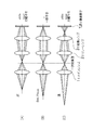
- FIG. 8 (A) to 8 (C) are diagrams showing separation states of images formed on the image sensor due to differences in the front pin, in-focus (best focus), and rear pin, respectively.
- the mirror 4 shown in FIG. 7 is omitted in order to compare the difference in separation due to focus.
- the focused image of the pupil-divided images is formed (matched) at the same position on the image sensor, but the part (A) of FIG. 8.
- the images to be the front and rear pins are formed (separated) at different positions on the image sensor.
- the electronic camera includes an imaging unit, a light amount distribution detection unit, an image shift amount detection unit, and an image processing unit.
- the imaging unit photoelectrically converts a subject image by the photographing optical system to generate photographed image data.
- the light quantity distribution detection unit detects the light quantity distribution by the light flux from the subject passing through different optical paths.
- the image shift amount detection unit detects image shift amounts at a plurality of locations in the photographing screen based on the light amount distribution.
- the image processing unit generates stereogram image data by changing the positional relationship of the subject in the captured image data in the horizontal direction based on the image shift amounts at a plurality of locations.
- the stereogram image data is corrected by changing the positional relationship of the subject in the stereogram image data in the horizontal direction. Since the stereogram image data can be corrected, it is possible to obtain a natural stereogram image with less discomfort for the user.
- Patent Document 2 pattern matching is performed on the left-eye image and the right-eye image captured by the left and right cameras with respect to the stereo image of either the left-eye image or the right-eye image as a reference. Then, a matching image for each pixel is specified, an intermediate position image is obtained by interpolating the inter-pixel distance between the matching images for each left and right pixel, and the right is obtained by extrapolating the inter-pixel distance between the matching images for each left and right pixel.
- a multi-view image creation method for obtaining an outside image and a left outside image is disclosed.
- the stereo matching processing unit (object detection means) 43 is processed by the image processing units 4A and 4B, and the above-described space setting unit in the two image data A and B stored in the memory unit 31.
- One or more corresponding points (objects) corresponding to each other with respect to the search space set by 42 are detected.
- the distance calculation unit (position calculation unit) 44 calculates the three-dimensional coordinate value (position information) of the corresponding point detected by the stereo matching processing unit 83 described above.
- the configurations of the photographing lenses 21A2 and 21B2 of the photographing unit 20A and the photographing unit 20B are different.
- the photographing lens 21A2 includes a zoom lens and a zoom lens driving unit (driving unit) (not shown) that drives the zoom lens.
- the photographing lens 21B2 includes: A fixed focus lens having a field angle equal to the wide angle end of the zoom lens of the photographing lens 21A2 is provided. With such a configuration, the cost is reduced.
- Patent Documents 4 to 6 are examples of a three-dimensional image generation technique using a single optical system.
- a large number of pixels are arranged on the same imaging surface, and in a solid-state imaging device that generates an image signal by photoelectrically converting a subject image formed on the imaging surface, Disclosed is a solid-state imaging device that is divided into groups and has different light-receiving incidence angles of pixels in each group.
- Patent Documents 7 to 11 are examples of a method for searching corresponding points between different viewpoint images, a technique for acquiring depth information by stereo matching, and a three-dimensional image generation technique using two-dimensional images and distance information (depth information). .
- Patent Document 12 in order to focus only on the main subject and intentionally blur other parts other than the main subject, the focus position is discretely moved by a predetermined amount of movement, and images are sequentially captured.
- a blur-enhanced image can be obtained by obtaining a plurality of images and combining the plurality of images.
- Patent Document 13 divides an image to be photographed into a plurality of areas, and an area that is a foreground or background of a main subject is imaged with a shift from a focal position corresponding to the distance of the area. Then, an image of each area is individually extracted from the captured images of each captured area, and these are combined to create one image. As a result, it is possible to easily take an image with a desired amount of blur.
- Patent Document 14 shows an example of a parallax map creation method.
- JP 2007-104248 A JP 2009-124308 A JP 2008-92007 paragraphs 0047-0048, 0071 JP2003-7994 Japanese Patent Laid-Open No. 2001-12916 JP 2001-016611 Japanese Unexamined Patent Publication No. 08-331607 JP 2008-141666 A JP 2009-14445 JP 2008-116309 Japanese Unexamined Patent Publication No. 2000-102040 JP 2008-271241 A JP 2003-209727 A JP 2010-226500 A
- the pupil division type stereoscopic imaging device that captures a parallax image and selectively generates a stereoscopic image by selectively acquiring image information that has passed through different pupil positions of the image imaging means, such as Patent Documents 4 to 6,
- the parallax at the in-focus position becomes 0, and the parallax corresponding to the blur (defocus amount) occurs at the non-in-focus position.
- the present invention provides a pupil-dividing stereoscopic imaging device capable of obtaining a planar image in which a desired portion such as the foreground and background is blurred with respect to a main subject, and a method of capturing the planar image in the pupil-dividing stereoscopic imaging device.
- a single imaging optical system and subject images that have passed through the first region and the second region having different predetermined directions of the imaging optical system are pupil-divided into two photoelectric conversion element groups, respectively.
- an imaging unit capable of continuously outputting a set of viewpoint images composed of a first image and a second image, and an amount of light beam formed on the photoelectric conversion element group of the imaging unit are adjusted.
- a diaphragm control unit capable of performing diaphragm control and a viewpoint at the first time point and the second time point
- An imaging control unit that controls the imaging unit to output a set of images, a parallax information calculation unit that calculates parallax information based on a set of viewpoint images output from the imaging unit at a first time point, and a second According to the parallax information calculated by the parallax information calculation unit and the parallax information calculation unit that generates a plane image based on the set of viewpoint images output from the imaging unit at the time point, the target pixel to be subjected to the blurring process of the plane image is determined, There is provided an imaging apparatus including a blur processing unit that performs blur processing on a target pixel of which a planar image is determined.
- the disparity information includes distance information of each pixel
- the blurring processing unit includes a distant view pixel whose distance information is farther than a predetermined first distance and / or a near view pixel whose distance information is smaller than a predetermined second distance. Is determined as a target pixel to be subjected to the blurring process of the planar image, and the blurring process is performed on the target pixel.
- the disparity information includes a disparity map that represents the amount of disparity between corresponding points in the set of viewpoint images, and the blurring processing unit blurs pixels that form corresponding points where the amount of disparity between corresponding points is equal to or greater than a predetermined value. Is determined as a target pixel, and blur processing is performed on the target pixel.
- the blur processing unit determines the pixels constituting the area designated by the user operation as the target pixels to be subjected to the blur processing of the planar image, and performs the blur processing on the target pixels.
- the disparity information includes a disparity map that represents the amount of disparity between corresponding points in the set of viewpoint images, and the blurring processing unit performs a blurring process to a degree corresponding to the amount of disparity between corresponding points on the pixels constituting each corresponding point. .
- the blur processing unit performs the blur processing of the degree specified by the user operation on the target pixel.
- the second time point is a time point when a planar image capturing instruction is input by a user operation
- the first time point is a time point before the second time point
- the second time point is a time point when a planar image capturing instruction is input by a user operation, and the first time point is a time point later than the second time point.
- the aperture control unit can execute the second aperture control for controlling the opening amount of the aperture unit so as to reduce the parallax between the corresponding points of the set of viewpoint images output from the imaging unit at the second time point.
- a difference calculation unit that calculates a difference between each of a plurality of viewpoint image sets output from the imaging unit at a plurality of first time points and a viewpoint image set output from the imaging unit at a second time point;
- the disparity information calculation unit obtains the disparity information based on the set of viewpoint images that minimizes the difference calculated by the difference calculation unit among the plurality of viewpoint image sets output from the imaging unit at a plurality of first time points. calculate.
- the difference includes a motion vector.
- a single imaging optical system and subject images that have passed through the first region and the second region having different predetermined directions of the imaging optical system are pupil-divided into two photoelectric conversion element groups, respectively.
- an imaging unit capable of continuously outputting a set of viewpoint images composed of a first image and a second image, and an amount of light beam formed on the photoelectric conversion element group of the imaging unit are adjusted.
- the first aperture control to be controlled is executed, and control is performed so that the opening amount of the aperture portion becomes smaller than the opening amount of the first aperture control at an arbitrary second time point that is before and after the first time point.
- Performing a second aperture control, a first time point and a second time point A step of controlling the imaging unit so that a set of viewpoint images is output at points, a step of calculating parallax information based on a set of viewpoint images output from the imaging unit at a first time point, and a second time point
- a step of creating a planar image based on the set of viewpoint images output from the imaging unit, and a target pixel to be subjected to the blurring process of the planar image is determined according to the calculated parallax information, and the target pixel for which the planar image is determined is blurred
- an imaging method for executing the processing is executed, and control is performed so that the opening amount of the aperture portion becomes smaller than the opening amount of the first aperture control at an arbitrary second time point that is before and after the
- the imaging apparatus and imaging method of the present invention captures a set of viewpoint images at the first time point with the open-side aperture, obtains parallax information from the set of viewpoint images, and at the second time point, the first time point A set of viewpoint images on the smaller aperture side, creating a planar image with less blur overall, determining a target pixel to which the planar image is to be blurred based on the parallax information, and determining the target pixel Apply blur processing.
- the pupil-division imaging device it is possible to blur the appropriate position according to the parallax information indicating the perspective of the subject and the magnitude of the parallax amount.
- Block diagram of a camera according to the first embodiment The figure which shows the structural example of the pupil division parallax image acquisition image pick-up element CCD. The figure which showed 1 pixel of 1st, 2nd pixel each 3 is an enlarged view of the main part.
- Flowchart of planar still image imaging processing according to the first embodiment Flowchart of planar still image imaging processing according to the second embodiment
- the figure which shows an example of the conventional monocular three-dimensional imaging device The figure which shows the separation state of the image imaged on an image sensor
- FIG. 1 is a block diagram showing an embodiment of a camera 1 according to the first embodiment.
- the camera 1 records the captured image on the memory card 54, and the operation of the entire apparatus is centrally controlled by a central processing unit (CPU) 40.
- CPU central processing unit
- the camera 1 is provided with an operation unit 38 such as a shutter button, a mode dial, a playback button, a MENU / OK key, a cross key, and a BACK key.
- a signal from the operation unit 38 is input to the CPU 40, and the CPU 40 controls each circuit of the camera 1 based on the input signal. For example, lens drive control, aperture drive control, shooting operation control, image processing control, image data control, Recording / reproduction control, display control of a liquid crystal monitor (LCD) 30 for stereoscopic display, and the like are performed.
- LCD liquid crystal monitor
- the ROM 10 stores programs executed by the CPU 40 and various data necessary for control, pixel defect information of the CCD 16, various constants / information relating to camera operation, and the like.
- the shutter button is an operation button for inputting an instruction to start shooting, and is configured by a two-stroke switch having an S1 switch that is turned on when half-pressed and an S2 switch that is turned on when fully pressed.
- the mode dial is selection means for selecting one of an auto shooting mode for shooting a still image, a manual shooting mode, a scene position such as a person, a landscape, a night view, and a moving image mode for shooting a moving image.
- the playback button is a button for switching to a playback mode in which a still image or a moving image of a stereoscopic image (3D image) or a planar image (2D image) that has been recorded is displayed on the liquid crystal monitor 30.
- the MENU / OK key is an operation key that has both a function as a menu button for instructing to display a menu on the screen of the liquid crystal monitor 30 and a function as an OK button for instructing confirmation and execution of selection contents. It is.
- the cross key is an operation unit for inputting instructions in four directions, up, down, left, and right, and functions as a button (cursor moving operation means) for selecting an item from the menu screen or instructing selection of various setting items from each menu. To do.
- the up / down key of the cross key functions as a zoom switch for shooting or a playback zoom switch in playback mode
- the left / right key functions as a frame advance (forward / reverse feed) button in playback mode.
- the BACK key is used to delete a desired object such as a selection item, cancel an instruction content, or return to the previous operation state.
- the image light indicating the subject is a solid-state image sensor (hereinafter referred to as “CCD”, which is a phase difference image sensor capable of acquiring a pupil-divided parallax image via the imaging lens 12 and the diaphragm 14, but may be a CMOS or the like.
- CCD solid-state image sensor
- the image is formed on 16 light receiving surfaces.
- the imaging lens 12 is driven by a lens driving unit 36 controlled by the CPU 40, and focus control, zoom (focal length) control, and the like are performed.
- the diaphragm 14 is composed of, for example, five diaphragm blades, and is driven by a diaphragm drive unit 34 controlled by the CPU 40.
- the diaphragm value (F value) F2.8 to F11 is controlled in five steps in increments of 1AV.
- the CPU 40 controls the diaphragm 14 via the diaphragm driving unit 34, and performs charge accumulation time (shutter speed) in the CCD 16, image signal readout control from the CCD 16, and the like via the CCD control unit 32.
- FIG. 2 is a diagram illustrating a configuration example of the CCD 16.
- the CCD 16 has odd-line pixels and even-line pixels arranged in a matrix, respectively.
- the converted image signals for the two planes can be read out independently.
- the plurality of light receiving elements corresponding to each pixel group form an effective pixel region for obtaining an effective imaging signal and an optical black region (hereinafter referred to as “OB region”) for obtaining a black level reference signal.
- the OB region is actually formed so as to surround the effective pixel region.
- the odd-numbered lines (1, 3, 5,...) Of the CCD 16 include pixels of R (red), G (green), and B (blue) color filters. Among them, GRGR... Pixel array lines and BGBG... Pixel array lines are alternately provided.
- the pixels in the even lines (2, 4, 6,%) are similar to the odd lines in the GRGR pixel array line and the BGBG pixel array. The lines are alternately provided, and the pixels are arranged so as to be shifted in the line direction by a half pitch with respect to the pixels of the even lines.
- the arrangement area of the first pixel and the second pixel constituting the image signal for two surfaces may or may not be the same.
- the first pixel exists over the entire effective pixel area, but the existence area of the second pixel may be only a specific area such as an AF area.
- the second pixels may be densely arranged over the entire effective pixel area or within a specific area, or may be roughly arranged.
- the second pixel number may be lower than the first pixel number as in the (D) part and (E) part of FIG.
- (D) and (E) represent the first pixel in the white portion and the second pixel in the black portion.
- the color filter for the black part may be RGB (part (D) in FIG. 2) or only G (part (E) in FIG. 2) for obtaining luminance information.
- the part (D) in FIG. 2 there is an advantage that it is not necessary to change the arrangement of the RGB color filter between the first pixel and the second pixel.
- the part (E) in FIG. There is an advantage that information can be used to detect the defocus amount.
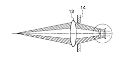
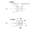
- FIG. 3 is a diagram showing each of the imaging lens 12, the diaphragm 14, and the first and second pixels of the CCD 16 in part (A) of FIG. 2, and FIG. 4 is an enlarged view of the main part of FIG. is there.
- a light beam passing through the exit pupil enters the normal CCD pixel (photodiode PD) via the microlens L without being restricted.
- a light shielding member 16A is formed on the first pixel and the second pixel of the CCD 16.
- the light shielding member 16A shields the right half or the left half of the light receiving surface of the first pixel and the second pixel (photodiode PD).
- the light shielding member 16A shields the upper half or the lower half of the light receiving surface of the first pixel and the second pixel (photodiode PD).
- the opening of the light shielding member 16A is located at a position deviated by a predetermined amount ⁇ from the optical axis Z of the microlens L in the right, left, upper, or lower direction (for example, leftward from the optical axis in the portion (B) in FIG. 4). 16B is provided. The light beam passes through the opening 16B and reaches the light receiving surface of the photodiode PD. That is, the light shielding member 16A functions as a pupil division member.
- the first pixel and the second pixel have different regions (right half / left half or upper half / lower half) where the light flux is restricted by the light shielding member 16A.
- the left half of the luminous flux is restricted at the first pixel and the right half of the luminous flux is restricted at the second pixel
- the right viewpoint image is obtained from the first pixel
- the left viewpoint image is obtained from the second pixel.
- the upper half of the luminous flux is restricted at the first pixel and the lower half of the luminous flux is restricted at the second pixel
- the lower viewpoint image is obtained from the first pixel and the upper viewpoint image is obtained from the second pixel.
- the outputs of the first pixel and the second pixel are out of phase or in phase, depending on the state of the rear pin, in-focus, and front pin. Since the phase difference between the output signals of the first pixel and the second pixel corresponds to the defocus amount of the imaging lens 12, AF control of the imaging lens 12 can be performed by detecting this phase difference (phase difference AF). .
- the CCD 16 having the above configuration is configured such that the first pixel and the second pixel have different regions (right half and left half) where the light flux is limited by the light shielding member 16A.
- the light blocking member 16A may not be provided, and the microlens L and the photodiode PD may be relatively shifted in the left-right direction, and the light flux incident on the photodiode PD may be limited by the shifting direction.
- the application range of the present invention is a camera that acquires a phase difference image by pupil division.
- the signal charge accumulated in the CCD 16 is read out as a voltage signal corresponding to the signal charge based on the readout signal applied from the CCD control unit 32.
- the voltage signal read from the CCD 16 is applied to the analog signal processing unit 18 where the R, G, and B signals for each pixel are sampled and held, amplified, and then applied to the A / D converter 20.
- the A / D converter 20 converts R, G, and B signals that are sequentially input into digital R, G, and B signals and outputs them to the image input controller 22.
- the digital signal processing unit 24 performs predetermined processing such as offset control, gain control processing including white balance correction and sensitivity correction, gamma correction processing, YC processing, etc., on the digital image signal input via the image input controller 22. Perform signal processing.
- predetermined processing such as offset control, gain control processing including white balance correction and sensitivity correction, gamma correction processing, YC processing, etc.
- the first image data read from the first pixels of the odd lines of the CCD 16 is processed as the left viewpoint image data, and the second of the even lines.
- the second image data read from the pixels is processed as right viewpoint image data.
- the first image data read from the first pixel is processed as the left viewpoint image data
- the second image read from the second pixels of the even lines is processed as right viewpoint image data.
- the first image data is not necessarily left viewpoint image data
- the second image data is not necessarily right viewpoint image data, and vice versa.
- the left viewpoint image data and right viewpoint image data (3D image data) processed by the digital signal processing unit 24 are input to the VRAM 50.
- the VRAM 50 includes an A area and a B area each storing 3D image data representing a 3D image for one frame.
- 3D image data representing a 3D image for one frame is rewritten alternately in the A area and the B area.
- the written 3D image data is read from an area other than the area in which the 3D image data is rewritten in the A area and the B area of the VRAM 50.
- the 3D image data read from the VRAM 50 is encoded by the video encoder 28 and output to a stereoscopic display liquid crystal monitor (LCD) 30 provided on the back of the camera, whereby a 3D subject image is displayed on the liquid crystal monitor 30. Displayed on the display screen.
- LCD liquid crystal monitor
- the liquid crystal monitor 30 is a stereoscopic display unit that can display stereoscopic images (left viewpoint image and right viewpoint image) as directional images each having a predetermined directivity by a parallax barrier.
- the left viewpoint image and the right viewpoint image may be viewed separately by using a lens, or by wearing dedicated glasses such as polarized glasses or liquid crystal shutter glasses.
- the CPU 40 starts the AF operation and the AE operation, and the focus lens in the imaging lens 12 is aligned via the lens driving unit 36. Control to come to the focal position.
- the image data output from the A / D converter 20 when the shutter button is half-pressed is taken into the AE detection unit 44.
- the AE detection unit 44 integrates the G signals of the entire screen or integrates the G signals that are weighted differently in the central portion and the peripheral portion of the screen, and outputs the integrated value to the CPU 40.
- the CPU 40 calculates the brightness of the subject (shooting Ev value) from the integrated value input from the AE detection unit 44, and the aperture value of the diaphragm 14 and the electronic shutter (shutter) of the CCD 16 that can obtain appropriate exposure based on this shooting Ev value. (Speed) is determined in accordance with a predetermined program diagram, the aperture 14 is controlled via the aperture drive unit 33 based on the determined aperture value (planar image aperture control), and CCD control is performed based on the determined shutter speed. The charge accumulation time in the CCD 16 is controlled via the unit 32. Note that the brightness of the subject may be calculated based on an external photometric sensor.
- the predetermined program diagram corresponds to the brightness of the subject (shooting EV value), and is a combination of the aperture value of the diaphragm 14 and the shutter speed of the CCD 16 or a combination of these and the shooting sensitivity (ISO sensitivity). )
- the conditions are designed.
- the predetermined program diagram includes a parallax priority program diagram and a focus priority program diagram.
- the F value is fixed at a constant small value.
- the F value to be fixed is increased, the parallax is weakened, and if the F value to be fixed is decreased, the parallax is increased. Therefore, the F value is fixed according to the parallax instructed by the user via the operation unit 38. And the program diagram may be switched.
- the parallax priority program diagram has the F value fixed at a constant small value, a main image and a sub image having a constant parallax can be taken.
- the shooting EV value is larger than 16 (when the shutter speed reaches the maximum value)
- the image is overexposed and cannot be shot.
- a configuration that can automatically reduce the amount of light by inserting an ND filter is added to the camera 1. Even if the shooting EV value is larger than 16, shooting is possible.
- the F value is fixed at a constant large value.
- the F value is fixed at a constant large value, so that an image that is in focus over the entire image can be taken.
- the AF processing unit 42 is a part that performs contrast AF processing or phase difference AF processing.
- contrast AF processing high-frequency components of image data within a predetermined focus area (such as a rectangular area in the center of the screen) of at least one of left viewpoint image data and right viewpoint image data are extracted.
- the AF evaluation value indicating the in-focus state is calculated by integrating the high frequency component.
- the AF control is performed by controlling the focus lens in the imaging lens 12 so that the AF evaluation value is maximized.
- phase difference AF processing when performing the phase difference AF processing, the phase difference between the image data corresponding to the first pixel and the second pixel in the predetermined focus area in the left viewpoint image data and the right viewpoint image data is detected, and this A defocus amount is obtained based on information indicating the phase difference.
- AF control is performed by controlling the focus lens in the imaging lens 12 so that the defocus amount becomes zero.
- the two pieces of image data temporarily stored in the memory 48 are appropriately read out by the digital signal processing unit 24, where predetermined signals including generation processing (YC processing) of luminance data and color difference data of the image data are performed. Processing is performed.
- the YC processed image data (YC data) is stored in the memory 48 again. Subsequently, the two pieces of YC data are respectively output to the compression / decompression processing unit 26 and subjected to predetermined compression processing such as JPEG (joint photographic experts group), and then stored in the memory 48 again.
- a multi-picture file (MP file: a file in a format in which a plurality of images are connected) is generated from two pieces of YC data (compressed data) stored in the memory 48, and the MP file is generated by the media controller 52. It is read and recorded in the memory card 54.
- MP file a file in a format in which a plurality of images are connected
- the defocus map creation unit 61 not only calculates the phase difference corresponding to the first pixel and the second pixel for each of the small areas included in the predetermined focus area, but substantially covers the entire effective pixel area.
- the calculation is performed for each of the plurality of small regions.
- the plurality of small areas that substantially cover the entire effective pixel area need not completely cover the entire effective pixel area, and may be densely or roughly arranged over the entire effective pixel area. That's fine. For example, each of the divided areas obtained by dividing the effective pixel area in a matrix by a predetermined unit (for example, 8 ⁇ 8 pixels), or less (for example, 1 ⁇ 1 pixel), or more (for example, 10 ⁇ 10 pixels).
- the phase difference is calculated.
- the phase difference is calculated for each divided region in a predetermined unit separated from the outer edge of the effective pixel region by a predetermined pitch (for example, one divided region or more or less).
- a predetermined pitch for example, one divided region or more or less.
- the defocus map creation unit 61 obtains a defocus amount corresponding to each of the small areas based on the phase difference calculated for each of the small areas.
- a set of defocus amounts corresponding to each of the small areas obtained over the entire effective pixel area is referred to as a defocus map.
- the defocus map creation unit 61 has a volatile storage medium such as a RAM, and temporarily stores the obtained defocus map.
- the defocus map creation unit 61 detects feature points and corresponding points between the viewpoint images in the stereo matching processing unit 83, and generates a defocus map based on a difference in position information between the feature points and the corresponding points. You may create it.
- the restoration filter storage unit 62 is configured by a nonvolatile storage medium such as a ROM, and the image height (distance from the image center, typically the optical axis center L of the imaging lens 12) of each small region in each viewpoint image. ) And a restoration filter corresponding to the defocus amount (or subject distance).
- the restoration unit 63 deconvolves the small area with the restoration filter selected for each small area of each viewpoint image, and restores the corresponding small area of the viewpoint image.
- the blur of the optical system in particular, the blur of the image corresponding to the peripheral pixels on the light receiving surface in which the unbalanced incidence of the light flux occurs is removed.
- the stereo matching processing unit (object detection means) 83 detects one or more corresponding points (objects) corresponding to each other between the two image data A and B stored in the memory 48 at the same timing.
- a processing method in the stereo matching processing unit 83 a known technique using a region-based method, a segment-based method, an isoluminance line method, or the like can be used. Further, the stereo matching may be passive or active. In addition, stereo matching between images having different numbers of pixels can be performed based on known techniques such as Patent Documents 3 and 7 to 11.
- the distance calculation unit 84 calculates the three-dimensional coordinate value (distance information) of the corresponding point detected by the stereo matching processing unit 83 described above.
- a calculation method of the distance information in the distance calculation unit 84 a known technique for calculation based on the principle of triangulation can be used.
- the stereo matching processing unit 83 and the distance calculation unit 84 may be configured by a program, or may be configured by an IC, an LSI, or the like.
- a parallax map (a reference viewpoint image, for example, an image representing another viewpoint image with a parallax amount from a corresponding point to image data A to another viewpoint image, for example, image data A) is technically related to distance information.
- the processing for the following distance information is equivalent and can be performed for the parallax map.
- the distance information to the subject or the parallax map is comprehensively referred to as parallax information.
- the calculation of the parallax information can be performed not by the camera 1 but by another information processing apparatus such as a personal computer.
- the acquisition pixel of the first image data and the acquisition pixel of the second image data may or may not have the same configuration.
- the first image data has color information and luminance information, but the second image data may have only luminance information.
- the second pixel may be a monochrome CCD that can receive an infrared region, and active stereo matching using infrared light as in Patent Document 7 may be employed.
- both the first image data and the second image data include at least luminance information.
- both the first image data and the second image data include color information.
- both the first image data and the second image data include luminance information and color information.
- the 3D image processing unit 85 can generate a 3D image from a set of viewpoint images acquired from the CCD 16. This is the same as in Patent Document 2. Note that three-dimensional image generation from parallax information can be performed based on known techniques such as Patent Documents 7 to 11. The three-dimensional image is generated when the shooting mode is set to “3D still image recording”, and a three-dimensional image having a desired amount of parallax is displayed on the LCD 30.
- the parallax amount of the 3D image generated by the 3D image processing unit 45 may be a fixed value or an arbitrary set value.
- the blur processing unit 86 performs low-pass filter processing to remove image signal components having a predetermined frequency or higher.
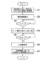
- FIG. 5 shows a flowchart of planar still image imaging processing according to the first preferred embodiment of the present invention. This process is started in response to the shooting mode being set to “2D still image recording”.
- the CPU 40 determines the aperture value X and the shutter speed according to the parallax priority program diagram in response to the shooting mode being set to “2D still image recording”. Then, the CPU 40 controls the aperture 14 via the aperture drive unit 33 based on the determined aperture value X (parallax priority aperture control), and the CCD 16 via the CCD control unit 32 based on the determined shutter speed. To control the charge accumulation time. As a result, left and right image data A and B (a set of viewpoint images) having parallax are acquired from the CCD 16. One of the image data A and B may be one of those displayed as a 2D through image on the LCD 30 or may be different from the 2D through image.
- the CPU 40 causes the stereo matching processing unit 83 and the distance calculation unit 84 to calculate stereo matching and distance information (parallax information).
- the stereo matching processing unit 83 performs stereo matching based on the image data A and B for one frame acquired in S1.
- the distance calculation unit 84 calculates distance information for each corresponding point detected by the stereo matching processing unit 83.
- the CPU 40 determines whether or not the shutter button of the operation unit 38 has been pressed (half-pressed) in the first stage. If Yes, the process proceeds to S4. If No, the determination is repeated.
- the CPU 40 determines the aperture value Y and the shutter speed according to the focus priority program diagram.
- the aperture value Y has a relationship that is larger than the aperture value X (becomes smaller aperture side).
- the aperture value X is in a relationship that is even smaller (open side) than the aperture value Y.
- the CPU 40 controls the aperture 14 via the aperture drive unit 33 based on the aperture value Y determined in S4 (focus priority priority aperture control).
- the CPU 40 determines whether or not the shutter button of the operation unit 38 has been pressed in the second stage (full press). In the case of Yes, it progresses to S6, and in the case of No, the said determination is repeated.
- the CPU 40 controls the charge accumulation time in the CCD 16 via the CCD control unit 32 based on the determined shutter speed together with the aperture control with focus priority in S4.
- left and right image data A and B having no parallax (blur or defocus amount) between the corresponding points (very small) are acquired.
- the CPU 40 adds the image signal for each of the two pixels corresponding to the same pupil-divided light beam for the left and right image data A and B. Thereby, a high-resolution 2D image is generated.
- the blur processing unit 86 determines a target pixel to be subjected to the blur processing based on the distance information (parallax information) for each corresponding point calculated in S2. Then, the blur processing unit 86 performs blur processing on the determined target pixel for blur processing.
- the target pixel for blurring is automatically determined. However, in addition to this, it may be determined based on a user operation. For example, the following pixels are determined as the target of the blurring process.
- the blur processing unit 86 refers to the distance information of each pixel, and a distant view pixel (for example, a subject image pixel of 5 m or more) farther than a predetermined first distance or a predetermined second distance.
- a small foreground pixel for example, a subject image pixel of 50 cm or less is determined as a target pixel for blurring.
- the blurring processing unit 86 refers to the parallax map of each pixel, and determines pixels that constitute corresponding points where the parallax amount between corresponding points is equal to or greater than a predetermined value (for example, two pixels) as a target pixel for blurring processing. To decide.
- a predetermined value for example, two pixels
- Example 3 In addition to Example 1 and / or Example 2, the blurring processing unit 86 determines each pixel included in the region designated by the user operation as a target pixel for blurring processing.
- the degree of the blurring process may be determined based on a user operation or may be automatically determined.
- the blur processing unit 86 sets the lower threshold of the frequency of the image signal component to be removed by the low-pass filter processing to ⁇ , and when the blur is designated, When the lower limit threshold is set to ⁇ and blurring weakness is designated, the lower limit threshold of the frequency is set to ⁇ .
- the blur processing unit 86 may change the degree of blur according to the amount of parallax indicated by the parallax map. That is, if the amount of parallax between certain corresponding points is large, the degree of blurring of those corresponding points is increased accordingly.
- the camera 1 captures a set of viewpoint images with an open aperture, obtains parallax information from the set of viewpoint images, captures a set of viewpoint images with a small aperture, and is totally unblurred 2D.
- An image is obtained, a location where the 2D image is to be blurred is determined based on the parallax information, and the location is blurred.
- the pupil-division imaging device it is possible to blur the appropriate position according to the parallax information indicating the perspective of the subject and the magnitude of the parallax amount.
- FIG. 6 shows a flowchart of planar still image imaging processing according to the preferred second embodiment of the present invention. This process is started in response to the shooting mode being set to “2D still image recording”.
- S11 to 14 are the same as S3 to 6.
- S15-16 are the same as S1-2.
- S17 is the same as S7.
- the timing of the acquisition is basically arbitrary, but in order to reduce the deviation of the composition of the set of viewpoint images at two different time points, preferably at close time points before and after the second step of pressing the shutter button. Should be acquired.
- a set of viewpoint images is acquired before pressing the second stage, for example, before pressing the first stage of the shutter button, as in the first embodiment, from the pressing of the second stage to the recording of the 2D image.
- the time lag can be small.
- the timing of pressing the first step of the shutter button occurs arbitrarily, the compositional deviation may become large in some cases.
- the diaphragm 14 is always opened to obtain one or a plurality of viewpoint image sets, and the viewpoint image sets and the 2D images acquired in S6 ( It is also possible to calculate the difference from each of the blurring target images and set the viewpoint image with the smallest difference as the set of viewpoint images for which the parallax information is calculated in S2.
- the CPU 40 generates a 2D image (candidate image) that is a candidate for calculating parallax information by combining each set of one or a plurality of viewpoint images acquired by opening the aperture 14 for each set. .
- the CPU 40 calculates a motion vector between the candidate image and the blurring target image.
- Various known techniques can be adopted as a method of detecting the motion vector. For example, first, the CPU 40 extracts a region (tracking target region) including a moving object from a candidate image acquired at a certain time (for example, first), stores it as a template in the VRAM 50, and then positions the template on the blurring target image.
- the motion vector is detected by calculating the correlation value while slightly shifting, and obtaining the region with the largest correlation (pattern matching method).
- the CPU 40 determines a set of viewpoint images corresponding to the candidate image with the smallest scalar vector of motion vectors as a 3D image for calculating disparity information, and calculates disparity information from the determined 3D image.
- the difference between the 3D image and the 2D image is reduced, and the target pixel for blurring processing is more accurately determined.
- the above-described calculation of the difference between the 3D image and the 2D image and the calculation of the parallax information according to the result are performed only when a moving body shooting mode such as a sports mode is selected, and in other cases, the second embodiment.
- the parallax information may be calculated from the 3D image acquired after the shutter is fully pressed.
- a liquid crystal filter is installed in the optical path before or after the diaphragm 14.
- the liquid crystal filter can set a transmittance corresponding to a small aperture or a transmittance corresponding to an open aperture according to a control signal from the CPU 40.
- the transmittance corresponding to the open aperture is a continuous or stepwise transmittance spreading concentrically, and the transmittance increases toward the center.
- the transmittance corresponding to the open aperture is substantially 100% (through).
- the CPU 40 opens the diaphragm 14, sets the transmittance corresponding to the open diaphragm in S1 or S15, and controls the liquid crystal filter so as to set the transmittance corresponding to the small diaphragm in S4 or S12. A 3D image and a 2D image are obtained.
- the CCD 16 it is possible to control the amount of light received by the CCD 16 in a shorter time by controlling the transmittance of the liquid crystal filter than by sequentially mechanically controlling the aperture diameter of the diaphragm 14, and between the 3D image acquisition and the 2D image acquisition.
- the time lag can be shortened and the target pixel for blurring can be determined more accurately.
Landscapes
- Engineering & Computer Science (AREA)
- Multimedia (AREA)
- Signal Processing (AREA)
- Physics & Mathematics (AREA)
- General Physics & Mathematics (AREA)
- Studio Devices (AREA)
- Testing, Inspecting, Measuring Of Stereoscopic Televisions And Televisions (AREA)
- Focusing (AREA)
- Automatic Focus Adjustment (AREA)
Abstract
La présente invention concerne un procédé selon lequel une caméra (1) forme un groupe d'images de point de vue à une ouverture maximale, obtient une information de disparité à partir du groupe d'images de point de vue, forme un groupe d'images de point de vue à une petite ouverture, obtient une image bidimensionnelle globalement nette, détermine un emplacement au niveau duquel un traitement de flou doit être effectué sur l'image bidimensionnelle sur la base de l'information de disparité, et effectue le traitement de flou à cet emplacement. Cela permet d'appliquer un flou dans un dispositif d'imagerie à pupilles en deux parties à une position appropriée dans laquelle la distance jusqu'au sujet, la grandeur de la disparité, ou analogue est indiquée.
Priority Applications (3)
| Application Number | Priority Date | Filing Date | Title |
|---|---|---|---|
| JP2012556758A JP5469258B2 (ja) | 2011-02-09 | 2011-12-12 | 撮像装置および撮像方法 |
| CN201180067221.5A CN103370943B (zh) | 2011-02-09 | 2011-12-12 | 成像装置和成像方法 |
| US13/956,846 US8823778B2 (en) | 2011-02-09 | 2013-08-01 | Imaging device and imaging method |
Applications Claiming Priority (2)
| Application Number | Priority Date | Filing Date | Title |
|---|---|---|---|
| JP2011-026429 | 2011-02-09 | ||
| JP2011026429 | 2011-02-09 |
Related Child Applications (1)
| Application Number | Title | Priority Date | Filing Date |
|---|---|---|---|
| US13/956,846 Continuation US8823778B2 (en) | 2011-02-09 | 2013-08-01 | Imaging device and imaging method |
Publications (1)
| Publication Number | Publication Date |
|---|---|
| WO2012108099A1 true WO2012108099A1 (fr) | 2012-08-16 |
Family
ID=46638328
Family Applications (1)
| Application Number | Title | Priority Date | Filing Date |
|---|---|---|---|
| PCT/JP2011/078649 Ceased WO2012108099A1 (fr) | 2011-02-09 | 2011-12-12 | Dispositif d'imagerie et procédé d'imagerie |
Country Status (4)
| Country | Link |
|---|---|
| US (1) | US8823778B2 (fr) |
| JP (1) | JP5469258B2 (fr) |
| CN (1) | CN103370943B (fr) |
| WO (1) | WO2012108099A1 (fr) |
Cited By (2)
| Publication number | Priority date | Publication date | Assignee | Title |
|---|---|---|---|---|
| JP2014238508A (ja) * | 2013-06-07 | 2014-12-18 | キヤノン株式会社 | 測距装置、撮像装置及び測距装置の制御方法 |
| JP2023128190A (ja) * | 2022-03-03 | 2023-09-14 | キヤノン株式会社 | 撮像装置、撮像装置の制御方法、およびプログラム |
Families Citing this family (12)
| Publication number | Priority date | Publication date | Assignee | Title |
|---|---|---|---|---|
| JP5920911B2 (ja) * | 2011-11-10 | 2016-05-18 | ソニー株式会社 | 情報処理装置、情報処理方法及びプログラム |
| KR101889932B1 (ko) * | 2012-07-25 | 2018-09-28 | 삼성전자주식회사 | 촬영 장치 및 이에 적용되는 촬영 방법 |
| US9459130B2 (en) | 2013-11-13 | 2016-10-04 | Deere & Company | System for measuring a liquid level and orientation |
| US9528871B2 (en) | 2013-11-13 | 2016-12-27 | Deere & Company | System for determining a liquid quantity and orientation |
| US10033992B1 (en) * | 2014-09-09 | 2018-07-24 | Google Llc | Generating a 3D video of an event using crowd sourced data |
| WO2016143913A1 (fr) | 2015-03-10 | 2016-09-15 | Canon Kabushiki Kaisha | Procédé de traitement d'image, dispositif de traitement d'image et appareil de capture d'image |
| TWI565323B (zh) * | 2015-09-02 | 2017-01-01 | 原相科技股份有限公司 | 分辨前景的成像裝置及其運作方法、以及影像感測器 |
| JP6678504B2 (ja) * | 2016-04-22 | 2020-04-08 | キヤノン株式会社 | 撮像装置及びその制御方法、プログラム並びに記憶媒体 |
| US10897558B1 (en) | 2018-09-11 | 2021-01-19 | Apple Inc. | Shallow depth of field (SDOF) rendering |
| JP7145048B2 (ja) * | 2018-11-16 | 2022-09-30 | キヤノン株式会社 | 撮像装置及びその制御方法、プログラム、記憶媒体 |
| JP7078172B2 (ja) * | 2019-03-14 | 2022-05-31 | オムロン株式会社 | 画像処理装置及び3次元計測システム |
| CN112487424A (zh) * | 2020-11-18 | 2021-03-12 | 重庆第二师范学院 | 一种计算机处理系统及计算机处理方法 |
Citations (4)
| Publication number | Priority date | Publication date | Assignee | Title |
|---|---|---|---|---|
| JPH1042314A (ja) * | 1996-07-22 | 1998-02-13 | Fuji Photo Film Co Ltd | 視差画像入力装置 |
| JP2003007994A (ja) * | 2001-06-27 | 2003-01-10 | Konica Corp | 固体撮像素子、立体カメラ装置及び測距装置 |
| JP2006105771A (ja) * | 2004-10-05 | 2006-04-20 | Canon Inc | 撮像装置および地形図作成装置 |
| JP2011215498A (ja) * | 2010-04-01 | 2011-10-27 | Sony Corp | 撮像装置 |
Family Cites Families (26)
| Publication number | Priority date | Publication date | Assignee | Title |
|---|---|---|---|---|
| KR100414629B1 (ko) | 1995-03-29 | 2004-05-03 | 산요덴키가부시키가이샤 | 3차원표시화상생성방법,깊이정보를이용한화상처리방법,깊이정보생성방법 |
| JPH08331607A (ja) * | 1995-03-29 | 1996-12-13 | Sanyo Electric Co Ltd | 三次元表示画像生成方法 |
| JP2000102040A (ja) * | 1998-09-28 | 2000-04-07 | Olympus Optical Co Ltd | 電子ステレオカメラ |
| US6807295B1 (en) | 1999-06-29 | 2004-10-19 | Fuji Photo Film Co., Ltd. | Stereoscopic imaging apparatus and method |
| JP3863319B2 (ja) * | 1999-06-29 | 2006-12-27 | 富士フイルムホールディングス株式会社 | 視差画像撮像装置及びカメラ |
| JP2001012916A (ja) * | 1999-06-30 | 2001-01-19 | Fuji Photo Film Co Ltd | 視差画像入力装置及び撮像装置 |
| JP2003018619A (ja) * | 2001-07-03 | 2003-01-17 | Olympus Optical Co Ltd | 立体映像評価装置およびそれを用いた表示装置 |
| US7286168B2 (en) * | 2001-10-12 | 2007-10-23 | Canon Kabushiki Kaisha | Image processing apparatus and method for adding blur to an image |
| JP3859131B2 (ja) * | 2002-01-11 | 2006-12-20 | 富士フイルムホールディングス株式会社 | デジタルカメラ |
| JP4448339B2 (ja) * | 2004-01-15 | 2010-04-07 | Hoya株式会社 | 立体視硬性鏡用光学系 |
| US7330577B2 (en) * | 2004-01-27 | 2008-02-12 | Densys Ltd. | Three-dimensional modeling of the oral cavity by projecting a two-dimensional array of random patterns |
| JP4227076B2 (ja) * | 2004-05-24 | 2009-02-18 | 株式会社東芝 | 立体画像を表示する表示装置及び立体画像を表示する表示方法 |
| JP2007104248A (ja) * | 2005-10-04 | 2007-04-19 | Nikon Corp | 電子カメラおよびプログラム |
| US7606424B2 (en) * | 2006-02-13 | 2009-10-20 | 3M Innovative Properties Company | Combined forward and reverse correlation |
| JP4914688B2 (ja) * | 2006-09-29 | 2012-04-11 | 富士フイルム株式会社 | 撮影装置 |
| JP4939901B2 (ja) * | 2006-11-02 | 2012-05-30 | 富士フイルム株式会社 | 距離画像生成方法及びその装置 |
| JP2008141666A (ja) * | 2006-12-05 | 2008-06-19 | Fujifilm Corp | 立体視画像作成装置、立体視画像出力装置及び立体視画像作成方法 |
| US8172402B2 (en) * | 2007-03-05 | 2012-05-08 | Thomson Licensing | Projection system for displaying at least one image based on three filtered primary colours |
| JP4582423B2 (ja) | 2007-04-20 | 2010-11-17 | 富士フイルム株式会社 | 撮像装置、画像処理装置、撮像方法、及び画像処理方法 |
| JP2009014445A (ja) * | 2007-07-03 | 2009-01-22 | Konica Minolta Holdings Inc | 測距装置 |
| JP4970195B2 (ja) * | 2007-08-23 | 2012-07-04 | 株式会社日立国際電気 | 人物追跡システム、人物追跡装置および人物追跡プログラム |
| JP4958233B2 (ja) * | 2007-11-13 | 2012-06-20 | 学校法人東京電機大学 | 多眼視画像作成システム及び多眼視画像作成方法 |
| EP2326101B1 (fr) * | 2008-09-18 | 2015-02-25 | Panasonic Corporation | Dispositif de reproduction de video stereoscopique et dispositif de reproduction de video stereoscopique |
| JP5375830B2 (ja) * | 2008-09-29 | 2013-12-25 | パナソニック株式会社 | 映像信号処理装置 |
| JP4737573B2 (ja) * | 2009-02-05 | 2011-08-03 | 富士フイルム株式会社 | 3次元画像出力装置及び方法 |
| JP2010226500A (ja) * | 2009-03-24 | 2010-10-07 | Toshiba Corp | 立体画像表示装置および立体画像表示方法 |
-
2011
- 2011-12-12 WO PCT/JP2011/078649 patent/WO2012108099A1/fr not_active Ceased
- 2011-12-12 JP JP2012556758A patent/JP5469258B2/ja not_active Expired - Fee Related
- 2011-12-12 CN CN201180067221.5A patent/CN103370943B/zh not_active Expired - Fee Related
-
2013
- 2013-08-01 US US13/956,846 patent/US8823778B2/en not_active Expired - Fee Related
Patent Citations (4)
| Publication number | Priority date | Publication date | Assignee | Title |
|---|---|---|---|---|
| JPH1042314A (ja) * | 1996-07-22 | 1998-02-13 | Fuji Photo Film Co Ltd | 視差画像入力装置 |
| JP2003007994A (ja) * | 2001-06-27 | 2003-01-10 | Konica Corp | 固体撮像素子、立体カメラ装置及び測距装置 |
| JP2006105771A (ja) * | 2004-10-05 | 2006-04-20 | Canon Inc | 撮像装置および地形図作成装置 |
| JP2011215498A (ja) * | 2010-04-01 | 2011-10-27 | Sony Corp | 撮像装置 |
Cited By (2)
| Publication number | Priority date | Publication date | Assignee | Title |
|---|---|---|---|---|
| JP2014238508A (ja) * | 2013-06-07 | 2014-12-18 | キヤノン株式会社 | 測距装置、撮像装置及び測距装置の制御方法 |
| JP2023128190A (ja) * | 2022-03-03 | 2023-09-14 | キヤノン株式会社 | 撮像装置、撮像装置の制御方法、およびプログラム |
Also Published As
| Publication number | Publication date |
|---|---|
| JPWO2012108099A1 (ja) | 2014-07-03 |
| JP5469258B2 (ja) | 2014-04-16 |
| US8823778B2 (en) | 2014-09-02 |
| CN103370943B (zh) | 2015-11-25 |
| US20130314510A1 (en) | 2013-11-28 |
| CN103370943A (zh) | 2013-10-23 |
Similar Documents
| Publication | Publication Date | Title |
|---|---|---|
| JP5469258B2 (ja) | 撮像装置および撮像方法 | |
| JP5640143B2 (ja) | 撮像装置及び撮像方法 | |
| JP5421829B2 (ja) | 撮像装置 | |
| CN102884802B (zh) | 三维成像装置和视点图像恢复方法 | |
| US8786676B2 (en) | Imaging device for generating stereoscopic image | |
| JP5595499B2 (ja) | 単眼立体撮像装置 | |
| JP5368350B2 (ja) | 立体撮像装置 | |
| US9282316B2 (en) | Stereoscopic imaging device and stereoscopic imaging method | |
| JP5788518B2 (ja) | 単眼立体撮影装置、撮影方法及びプログラム | |
| JP5871989B2 (ja) | 撮影装置、撮影方法及びプログラム | |
| JP2011259168A (ja) | 立体パノラマ画像撮影装置 | |
| US9106900B2 (en) | Stereoscopic imaging device and stereoscopic imaging method | |
| JP5457240B2 (ja) | 立体撮像装置 | |
| JP2012124650A (ja) | 撮像装置および撮像方法 | |
| JP2014063190A (ja) | 撮像装置 |
Legal Events
| Date | Code | Title | Description |
|---|---|---|---|
| 121 | Ep: the epo has been informed by wipo that ep was designated in this application |
Ref document number: 11858322 Country of ref document: EP Kind code of ref document: A1 |
|
| ENP | Entry into the national phase |
Ref document number: 2012556758 Country of ref document: JP Kind code of ref document: A |
|
| NENP | Non-entry into the national phase |
Ref country code: DE |
|
| 122 | Ep: pct application non-entry in european phase |
Ref document number: 11858322 Country of ref document: EP Kind code of ref document: A1 |