WO2012108112A1 - 冷凍サイクル装置 - Google Patents
冷凍サイクル装置 Download PDFInfo
- Publication number
- WO2012108112A1 WO2012108112A1 PCT/JP2011/080271 JP2011080271W WO2012108112A1 WO 2012108112 A1 WO2012108112 A1 WO 2012108112A1 JP 2011080271 W JP2011080271 W JP 2011080271W WO 2012108112 A1 WO2012108112 A1 WO 2012108112A1
- Authority
- WO
- WIPO (PCT)
- Prior art keywords
- pipe
- temperature
- refrigeration cycle
- tube
- low
- Prior art date
- Legal status (The legal status is an assumption and is not a legal conclusion. Google has not performed a legal analysis and makes no representation as to the accuracy of the status listed.)
- Ceased
Links
Images





Classifications
-
- F—MECHANICAL ENGINEERING; LIGHTING; HEATING; WEAPONS; BLASTING
- F28—HEAT EXCHANGE IN GENERAL
- F28D—HEAT-EXCHANGE APPARATUS, NOT PROVIDED FOR IN ANOTHER SUBCLASS, IN WHICH THE HEAT-EXCHANGE MEDIA DO NOT COME INTO DIRECT CONTACT
- F28D7/00—Heat-exchange apparatus having stationary tubular conduit assemblies for both heat-exchange media, the media being in contact with different sides of a conduit wall
- F28D7/10—Heat-exchange apparatus having stationary tubular conduit assemblies for both heat-exchange media, the media being in contact with different sides of a conduit wall the conduits being arranged one within the other, e.g. concentrically
- F28D7/106—Heat-exchange apparatus having stationary tubular conduit assemblies for both heat-exchange media, the media being in contact with different sides of a conduit wall the conduits being arranged one within the other, e.g. concentrically consisting of two coaxial conduits or modules of two coaxial conduits
-
- F—MECHANICAL ENGINEERING; LIGHTING; HEATING; WEAPONS; BLASTING
- F25—REFRIGERATION OR COOLING; COMBINED HEATING AND REFRIGERATION SYSTEMS; HEAT PUMP SYSTEMS; MANUFACTURE OR STORAGE OF ICE; LIQUEFACTION SOLIDIFICATION OF GASES
- F25B—REFRIGERATION MACHINES, PLANTS OR SYSTEMS; COMBINED HEATING AND REFRIGERATION SYSTEMS; HEAT PUMP SYSTEMS
- F25B40/00—Subcoolers, desuperheaters or superheaters
-
- F—MECHANICAL ENGINEERING; LIGHTING; HEATING; WEAPONS; BLASTING
- F28—HEAT EXCHANGE IN GENERAL
- F28F—DETAILS OF HEAT-EXCHANGE AND HEAT-TRANSFER APPARATUS, OF GENERAL APPLICATION
- F28F9/00—Casings; Header boxes; Auxiliary supports for elements; Auxiliary members within casings
- F28F9/02—Header boxes; End plates
- F28F9/0246—Arrangements for connecting header boxes with flow lines
-
- F—MECHANICAL ENGINEERING; LIGHTING; HEATING; WEAPONS; BLASTING
- F25—REFRIGERATION OR COOLING; COMBINED HEATING AND REFRIGERATION SYSTEMS; HEAT PUMP SYSTEMS; MANUFACTURE OR STORAGE OF ICE; LIQUEFACTION SOLIDIFICATION OF GASES
- F25B—REFRIGERATION MACHINES, PLANTS OR SYSTEMS; COMBINED HEATING AND REFRIGERATION SYSTEMS; HEAT PUMP SYSTEMS
- F25B2309/00—Gas cycle refrigeration machines
- F25B2309/06—Compression machines, plants or systems characterised by the refrigerant being carbon dioxide
Definitions
- the present invention relates to a refrigeration cycle apparatus having an internal heat exchanger used in a vapor compression refrigeration cycle of a vehicle air conditioner.
- a heat pump cycle that performs an air conditioning operation using a refrigerant such as carbon dioxide that has an internal heat exchanger as described in Patent Document 1.
- a cycle device heat exchange is performed between a high-temperature and high-pressure liquid-phase refrigerant and a low-temperature and low-pressure gas-phase refrigerant, thereby reducing the specific enthalpy of the evaporator inlet refrigerant and increasing the refrigeration effect. Improvements in cycle efficiency and capacity have been made.
- An object of the present invention is to provide a refrigeration cycle apparatus capable of increasing the operating efficiency and operating capacity as much as possible by increasing the amount of heat exchange in the internal heat exchanger while suppressing the suction superheat degree of the compressor small.
- a refrigeration cycle apparatus includes: In the refrigeration cycle, one of the low-temperature and low-pressure refrigerant flowing from the evaporator outlet to the compressor inlet and the high-temperature and high-pressure refrigerant flowing from the condenser outlet to the evaporator inlet is circulated in the inner space of the inner pipe, and the other is While arranging a double pipe type internal heat exchanger circulated in the space between the inner pipe and the outer pipe, A portion of the inner tube overlaps the tube walls in the axial direction, and an inner space in the inner tube and an outer space between the inner tube and the outer tube are arranged between the overlapped tube walls.
- the two-phase refrigerant is added to the low-temperature and low-pressure gas-phase refrigerant after passing through the evaporator, and the high-temperature and high-pressure refrigerant is more effectively cooled by the latent heat of vaporization of the two-phase refrigerant, thereby increasing the amount of heat exchange in the evaporator. can do.
- the temperature rise of the gas-phase refrigerant is also suppressed by the high cooling function by the two-phase refrigerant, the degree of superheat at the evaporator outlet and the compressor inlet can be reduced, the performance deterioration of the compressor can be suppressed, and the suction refrigerant density To increase driving efficiency.
- the refrigerant flow rate passing through the evaporator can be reduced, pressure loss of the refrigerant in the evaporator can be suppressed, and the refrigerating capacity and cycle efficiency can be improved. It becomes.
- the pressure loss due to the outflow can be suppressed by the configuration in which a part of the high-temperature and high-pressure side refrigerant flows out in parallel with the flow direction of the low-temperature and low-pressure side refrigerant. Further, by appropriately adjusting the bypass flow rate and the outflow speed of the high-temperature and high-pressure side refrigerant, it is possible to provide an ejector effect. In this case, one of the power sources for sucking and conveying the low-temperature and low-pressure side refrigerant to the compressor. And contributes to the power saving of the refrigeration cycle.
- FIG. 1 is a schematic view of a refrigeration cycle apparatus according to an embodiment of the present invention. It is a perspective view which shows the internal heat exchanger used in the refrigeration cycle apparatus of FIG. Sectional drawing which shows 1st Embodiment of the internal structure of the bypass channel periphery part in the said internal heat exchanger [(A) is AA arrow sectional drawing of (B), (B) is a longitudinal cross-sectional view, (C ) Is a front view of a double tube].
- FIG. 8A is a cross-sectional view taken along the line AA of FIG. 8B
- FIG. 5B is a vertical cross-sectional view showing a second embodiment of the internal structure.
- FIG. 9B is a cross-sectional view taken along the line AA of (B), and FIG. (B) is a vertical cross-sectional view showing a third embodiment of the internal structure.
- the figure which similarly shows 4th Embodiment of an internal structure [(A) is AA arrow sectional drawing of (B), (B) is a longitudinal cross-sectional view, (C) is a front view of a double pipe.] is there.
- FIG. 9A is a cross-sectional view taken along the line AA of FIG. 5B
- FIG. 5B is a vertical cross-sectional view showing a fifth embodiment of the internal structure.
- FIG. 9B is a cross-sectional view taken along the line AA of (B), and (B) is a vertical cross-sectional view, similarly showing a sixth embodiment of the internal structure. It is a longitudinal cross-sectional view which similarly shows 7th Embodiment (A) and 8th Embodiment (B) of an internal structure. It is a diagram which shows the refrigerating cycle characteristic of the refrigerating cycle apparatus which concerns on this invention.
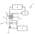
- FIG. 1 is a schematic view of a refrigeration cycle apparatus 1 according to an embodiment of the present invention.
- the refrigerant circulates in the system, and the high-temperature and high-pressure liquid-phase refrigerant that has flowed out of the condenser 2 is outside of the annular shape between the outer pipe 31 and the inner pipe 32 of the double-tube internal heat exchanger 3.
- the refrigerant flows through the space and mainly flows into the evaporator 4 through the expansion valve 10, but a part of the refrigerant is decompressed and expanded via the bypass passage B formed in the inner pipe 32 and bypasses the evaporator 4 to bypass the inner pipe 32. Flows in.
- the refrigerant evaporated in the evaporator 4 flows out from the evaporator 4, then flows into the inner pipe 32 of the internal heat exchanger 3, merges with the bypassed refrigerant, and then flows into the compressor 5.
- the refrigerant compressed in the compressor 5 flows into the condenser 2 and is condensed.
- FIG. 2 is a perspective view showing a double-pipe internal heat exchanger 3 used in the refrigeration cycle apparatus 1 of FIG.
- a liquid phase refrigerant inflow pipe 6 that causes the liquid phase refrigerant from the condenser 2 to flow into the outer pipe 31 in the double pipe 30, and a liquid phase refrigerant that causes the liquid layer refrigerant after heat exchange in the outer pipe 31 to flow out to the expansion valve 10.
- a tube 9 is connected.
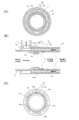
- FIG. 3 is a cross-sectional view showing a first embodiment of the internal structure around the bypass passage in the internal heat exchanger 3.
- the outer pipe 31 and the inner pipe 32 are integrally formed via ribs arranged in the radial direction, and the end of the double pipe 30 on the outer peripheral wall of the open end portion on the gas phase refrigerant inflow side on the liquid phase refrigerant outflow side.
- a cap 33 is inserted and fixed.
- the end cap 33 has an end portion of the gas-phase refrigerant inflow pipe 8 fixed through the end wall, and an end portion of the liquid-phase refrigerant outflow pipe 7 fixed through the peripheral wall.
- the gas-phase refrigerant inflow pipe 8 constitutes a part of the inner pipe inside the internal heat exchanger 3.
- the inner peripheral surface of the end of the inner pipe 32 is cut into a conical surface constricted inward, and the conical surface is further divided by 3 at equal intervals in the circumferential direction (every 120 degrees).
- Engagement surfaces 32a are formed leaving portions, and a communication groove 32b is formed by cutting a predetermined amount in the axial direction between the engagement surfaces 32a.
- the gas-phase refrigerant inflow pipe 8 has a small-diameter portion 8A having an outer diameter that is a predetermined amount smaller than the inner diameter of the inner pipe 32 at the end connected to the end of the inner pipe 32 in the internal heat exchanger 3.
- a portion connecting the small diameter portion 8A and the large diameter portion 8B having the same inner and outer diameter as the inner tube 32 is formed in a conical portion 8C having the same cone angle as the engagement surface 32a.
- the outer peripheral surface of the conical portion 8C of the gas-phase refrigerant inflow pipe 8 is abutted and joined to the engagement surface 32a of the inner pipe 32, whereby the axes of the gas-phase refrigerant inflow pipe 8 and the inner pipe 32 coincide with each other.
- An annular gap 11 is formed between the inner peripheral surface of the end portion of the pipe 32 and the outer peripheral surface of the end portion of the small diameter portion 8A of the gas-phase refrigerant inflow tube 8.
- the communication groove 32b and the annular gap 11 communicate the annular outer space S1 between the outer tube 31 through which the high-temperature and high-pressure refrigerant flows and the inner space S2 in the inner tube 32.
- a bypass passage B1 is formed.
- the high-temperature and high-pressure liquid-phase refrigerant flowing in the outer space S1 exchanges heat with the low-temperature and low-pressure gas-phase refrigerant flowing in the inner space S2 via the inner wall surface of the inner tube 32.
- a part of the liquid refrigerant is bypassed to the inner space S ⁇ b> 2 in the inner pipe 32 via the bypass passage B ⁇ b> 1 including the communication groove 32 b and the annular gap 11.
- the bypass passage B1 is formed so that a flow resistance within a predetermined range is generated in the refrigerant flow passing therethrough, whereby a part of the high-temperature and high-pressure refrigerant is decompressed and expanded into a low-temperature and low-pressure two-phase refrigerant. It is bypassed while being converted, and functions to join the low-temperature and low-pressure gas-phase refrigerant after passing through the evaporator 4. Cycle efficiency can be improved by bypassing and joining the refrigerant in such a configuration and using the latent heat of vaporization of the bypassed refrigerant for cooling the high-temperature and high-pressure refrigerant (see FIG. 10). Further, by increasing the cooling amount of the high-temperature and high-pressure refrigerant, it is possible to keep the dryness of the refrigerant at the inlet of the evaporator 4 low, thereby further improving the refrigeration efficiency and the cycle efficiency.
- the cooling amount due to heat exchange with the outside air in the evaporator 4 decreases by the bypass amount.
- the refrigerating capacity and the cycle efficiency can be improved by the amount that the pressure loss due to the bypass refrigerant passing through the evaporator can be reduced.
- the amount of cooling of the high-temperature and high-pressure refrigerant is increased using the latent heat of vaporization of the bypass refrigerant, the temperature rise due to heat exchange between the gas-phase refrigerant circulating in the inner space S2 and the high-temperature and high-pressure refrigerant can be suppressed.
- the increase in the degree of suction superheat at the inlet of the compressor 5 can be suppressed to suppress a decrease in the durability of the compressor 5, the discharge hose, etc., and the decrease in the suction refrigerant density can be suppressed to increase the operating efficiency. it can.
- the shape of the bypass passage B1 (passage cross-sectional area, passage length, etc.) is set so as to reduce the suction superheat degree at the compressor inlet to near zero (see FIG. 10).
- the bypassed high-temperature / high-pressure refrigerant flow rate is set to 5 to 35% of the high-temperature / high-pressure refrigerant flow rate upstream of the bypass passage.
- bypass passage B1 since the bypass refrigerant flows out in the same direction as the flow direction of the gas-phase refrigerant in the inner space S2, turbulence when the bypass refrigerant flows out can be suppressed, and pressure loss And the refrigerating capacity and cycle efficiency can be sufficiently increased.
- the refrigerant since the refrigerant can be made to flow out uniformly from the annular gap 11 over the entire circumference, the disturbance suppressing function is enhanced.
- the bypass refrigerant flowing out in the same direction can exert an ejector effect that assists the flow of the gas-phase refrigerant.
- the driving energy of the compressor can be reduced, and the refrigerating capacity and cycle efficiency can be further increased.
- the bypass passage B1 is preferably formed only on the upstream side of the inner pipe 32.
- the outer pipe 31 is formed in a range (3D) that is three times as long as the outer diameter (D) of the outer pipe 31 from the end surface of the liquid refrigerant outlet side toward the downstream side of the inner pipe 32. It is preferred that By forming the bypass passage B1 at such a position, an effective heat exchange area on the tube wall surface of the inner tube 32 can be sufficiently secured, and heat exchange of the refrigerant can be performed efficiently.
- bypass passage B1 is formed between the inner pipe (the inner pipe 32 and the gas-phase refrigerant inflow pipe 8) divided inside the internal heat exchanger 3, processing is easy and cost as described below. Reduction can be achieved.
- the inner pipe of the double pipe protrudes from the end face of the outer pipe, and further passes through the end wall of the end cap, so that the external gas-phase refrigerant inflow pipe It becomes a structure to connect with.
- the bypass hole which penetrates a pipe wall in an inner pipe like patent 2985882 it becomes a structure which forms a bypass hole in the inner pipe which protruded from the end surface of the outer pipe.
- the inner tube and the outer tube of the double tube may be cut at the same end face, and welding is performed by connecting the liquid phase refrigerant inflow pipe, the outer pipe, and the gas phase refrigerant outflow pipe to the end cap. If it is applied to the joint, the number of welds can be reduced.
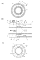
- FIG. 4 is a cross-sectional view showing a second embodiment of the internal structure around the bypass passage.
- a plurality of axially extending grooves 32c are arranged in the inner peripheral wall of the inner pipe 31 of the double pipe 30 in the circumferential direction, and the outer peripheral surface of the small-diameter portion 8A of the gas-phase refrigerant inflow pipe 8 is It is joined to the inner peripheral surface of the inner tube 32 formed to have the same diameter as the outer peripheral surface.
- a size set so that an appropriate amount of bypass refrigerant can flow between the outer peripheral surface of the conical portion 8C between the small diameter portion 8A and the large diameter portion 8B of the gas-phase refrigerant inflow pipe 8 and the open end of the groove 32c.
- the gap 12 is opened.
- a bypass passage B2 that connects the outer space S1 and the inner space S2 is formed by the gap 12 and the groove 32c between the outer peripheral surface of the small diameter portion 8A and the inner peripheral surface of the inner tube 32.
- the axial centers of the gas-phase refrigerant inflow pipe 8 and the inner pipe 32 are made to coincide with each other with high accuracy only by fitting the small-diameter portion 8A of the gas-phase refrigerant inflow pipe 8 into the inner pipe 32 and joining them.
- the bypass passage B2 having a uniform passage area in the circumferential direction can be easily formed.
- the groove 32c on the inner peripheral surface of the inner tube 32 can be easily formed by broaching or the like.
- the formation of the groove 32c can increase the heat exchange area and increase the heat exchange capacity of the internal heat exchanger 3.
- the bypass passage B2 can be easily formed using this groove.
- FIG. 5 is a cross-sectional view showing a third embodiment of the internal structure around the bypass passage.
- a plurality of axially extending grooves 8a are provided in the circumferential direction on the outer peripheral surface of the small diameter portion 8A of the gas-phase refrigerant inflow pipe 8, and the outer peripheral surface of the small diameter portion 8A is the inner peripheral surface of the inner tube 32. It is made to join. Further, a gap 13 having a size set so that an appropriate amount of the bypass refrigerant can flow is opened between the outer peripheral surface of the conical portion 8C and the end surface of the inner tube 32.
- a bypass passage B3 that connects the outer space S1 and the inner space S2 is formed by the gap 13 and the groove 8a.
- the small-diameter portion 8A of the gas-phase refrigerant inflow pipe 8 is simply fitted into the inner pipe 32 and joined, and the gas-phase refrigerant inflow pipe 8 and the inner pipe 32 are connected.
- the shaft centers can be made to coincide with each other with high accuracy, and the bypass passage B3 having a uniform passage area in the circumferential direction can be easily formed.
- the groove 8a of the small diameter portion 8A can be easily formed by drawing or the like.
- tube is also employable for this invention. 6 to 8, the low-temperature and low-pressure gas-phase refrigerant is circulated in the outer space S1 between the outer tube 31 and the inner tube 32, and the high-temperature and high-pressure liquid-phase refrigerant is circulated in the inner space S2 in the inner tube 32. It is.
- an end cap 34 fixed to the outer peripheral wall of the open end portion on the gas phase refrigerant inflow side on the liquid phase refrigerant outflow side of the double pipe 30 passes through the end wall of the liquid phase refrigerant outflow pipe 7.
- the end is fixed, and the end of the gas-phase refrigerant inflow pipe 8 is fixed through the peripheral wall.
- the liquid phase refrigerant outflow pipe 7 constitutes a part of the inner pipe 32 inside the internal heat exchanger 3.
- a bypass passage B4 that bypasses the liquid-phase refrigerant flowing in the inner space S2 to the outer space S1 is formed as follows.
- the fourth embodiment corresponds to the embodiment of FIG. 3, and the outer peripheral surface of the end portion of the inner tube 32 is cut into a conical surface that expands outward, and the conical surface is equally spaced in the circumferential direction.
- Engagement surfaces 32d are formed at three positions (every 120 degrees), and a predetermined amount of the engagement surfaces 32d are cut in the axial direction to form communication grooves 32e.
- the liquid-phase refrigerant outflow pipe 7 has a large-diameter portion whose inner diameter is larger by a predetermined amount than the outer diameter of the inner pipe 32 at the end connected to the end of the inner pipe 32 of the double pipe in the internal heat exchanger 3.
- a portion connecting the large diameter portion 7A and the small diameter portion 7B having the same inner and outer diameters as the inner tube 32 is formed in a conical portion 7C having the same cone angle as the engagement surface 32d.
- the inner peripheral surface of the conical portion 7C of the liquid-phase refrigerant outflow pipe 7 is abutted against and joined to the engagement surface 32d of the inner pipe 32, so that the axes of the inner pipe 32 and the liquid-phase refrigerant outflow pipe 7 coincide.
- An annular gap 14 is formed between the outer peripheral surface of the end portion of the inner pipe 32 and the inner peripheral surface of the end portion of the large-diameter portion 7A of the liquid-phase refrigerant outflow tube 7.
- FIG. 7 shows a fifth embodiment corresponding to the embodiment of FIG. 4.
- a plurality of grooves 32 f extending in the axial direction are arranged in the circumferential direction on the outer peripheral surface of the inner pipe 32, and the end of the liquid-phase refrigerant outflow pipe 7.
- the inner peripheral surface of the portion and the outer peripheral surface of the inner tube 32 formed to have the same diameter as the inner peripheral surface are joined. Further, a size set so that an appropriate amount of bypass refrigerant can flow between the outer peripheral surface of the conical portion 7C between the large diameter portion 7A and the small diameter portion 7B and the open end of the groove 32f.
- the gap 15 is opened.
- a bypass passage B5 that connects the inner space S2 and the outer space S1 is formed by the gap 15 and the groove 32f between the inner peripheral surface of the large-diameter portion 7A and the outer peripheral surface of the inner tube 32.
- the shaft of the inner pipe 32 and the liquid-phase refrigerant outflow pipe 7 can be obtained simply by fitting the large-diameter portion 7A of the liquid-phase refrigerant outflow pipe 7 into the inner pipe 32 and joining them.
- the centers can be made to coincide with each other with high accuracy, and the bypass passage B5 having a uniform passage area in the circumferential direction can be easily formed.
- the groove 32f may be formed from the end surface of the large-diameter portion 7A to the depth of the pipe by a predetermined amount so that the bypass refrigerant can flow out in parallel with the flow direction of the gas-phase refrigerant.
- FIG. 8 shows a sixth embodiment corresponding to the embodiment of FIG. 5, and a plurality of grooves 7 a extending in the axial direction are arranged in the circumferential direction on the inner peripheral surface of the large-diameter portion 7 ⁇ / b> A of the liquid-phase refrigerant outflow pipe 7. Then, the inner peripheral surface of the large diameter portion 7A and the outer peripheral surface of the inner tube 32 are joined. Further, as in the fifth embodiment, a gap 15 having a size set so that an appropriate amount of bypass refrigerant can flow between the inner peripheral surface of the conical 9C and the end surface of the inner tube 32 is opened.
- the bypass 15 that communicates the inner space S2 and the outer space S1 is formed by the gap 15 and the groove 7a.
- the present embodiment also includes the inner pipe 32 and the liquid-phase refrigerant outflow pipe 7 simply by fitting the large-diameter portion 7 ⁇ / b> A of the liquid-phase refrigerant outflow pipe 7 into the inner pipe 32.
- the bypass passage 6 having a uniform passage area in the circumferential direction can be easily formed.
- the bypass passage B is formed by connecting the liquid-phase refrigerant outflow pipe 7 or the gas-phase refrigerant inflow pipe 8 in the internal heat exchanger 3 to the inner pipe 32 as a divided inner pipe.
- the bypass passage B may be formed without dividing the inner pipe 32.
- a bypass passage B7 is formed by an annular gap inside the pipe member 51 that is fitted and fixed, or a plurality of axially formed grooves 51a formed in this portion.
- the outer space S1 is fitted into a plurality of communication holes 32h intermittently formed around the inner pipe 32 through which the high-temperature and high-pressure liquid refrigerant flows, and the inner circumference of the inner pipe 32.
- a bypass passage B8 is formed by an annular gap outside the pipe member 61 fixed in place or a plurality of axially formed grooves 61a formed in this portion.
- the refrigeration cycle apparatus according to the present invention is widely used in a vapor compression refrigeration cycle of a vehicle air conditioner.
Landscapes
- Engineering & Computer Science (AREA)
- Physics & Mathematics (AREA)
- Thermal Sciences (AREA)
- Mechanical Engineering (AREA)
- General Engineering & Computer Science (AREA)
- Heat-Exchange Devices With Radiators And Conduit Assemblies (AREA)
Abstract
高い運転効率および運転能力を保持しつつ、内部熱交換器の熱交換量を従来よりも高めることができる冷凍サイクル装置を提供する。 冷凍サイクル内を循環する冷媒が管内を蒸発器出口から圧縮機入口へと流れる内管32と、前記冷媒が管内を凝縮器出口から蒸発器入口へと流れる外管31とからなる二重管式内部熱交換器を有し、外管31と内管32との間の外側空間S1を流れる高温高圧の液相冷媒の一部を、内管32内の内側空間S2にバイパスさせるバイパス通路B1を、気相冷媒流入管8の端部の小径部8Aを内管32の端部内側に嵌挿し、気相冷媒流入管8と内管32との軸方向にオーバーラップさせた管壁相互間に形成した。
Description
本発明は、車両用空調装置の蒸気圧縮式冷凍サイクル等に用いられる、内部熱交換器を有する冷凍サイクル装置に関する。
二酸化炭素等の冷媒を用いて冷暖房運転を行うヒートポンプサイクルにおいて、特許文献1に記載されるような内部熱交換器を有するものが知られている。このようなサイクル装置においては、高温高圧の液相冷媒と低温低圧の気相冷媒との間で熱交換を行うことによって、蒸発器入口冷媒の比エンタルピを減少させ、冷凍効果を増加させることでサイクルの効率および能力の向上が図られている。
従来の冷凍サイクル装置に使用される内部熱交換器においては、熱交換量を増やし過ぎると、圧縮機の吸入過熱度が異常に高くなり、圧縮機および吐出ホースの耐久性に悪影響を及ぼす恐れがあった。このような悪影響を回避するために、内部熱交換器を運転するにあたっては、圧縮機の吸入過熱度を所定範囲内に抑えることができる程度に熱交換量の上限を設定する必要があり、運転効率及び運転能力を十分に高めることができなかった。
本発明は、圧縮機の吸入過熱度を小さく抑制しつつ、内部熱交換器における熱交換量を増大させて、運転効率および運転能力をできる限り高めることができる冷凍サイクル装置を提供することを目的とする。
上記課題を解決するために、本発明に係る冷凍サイクル装置は、
冷凍サイクルにおける、蒸発器出口から圧縮機入口へと流れる低温低圧冷媒と、凝縮器出口から蒸発器入口へと流れる高温高圧冷媒との、いずれか一方を内管の内側空間に流通させ、他方を前記内管と外管との間の空間に流通させた二重管式内部熱交換器を配設すると共に、
内管の一部に、管壁同士を軸方向にオーバーラップさせると共に、内管内の内側空間と、内管と外管との間の外側空間と、を、前記オーバーラップされた管壁間を経由して連通させたバイパス通路を形成し、高温高圧冷媒の一部が前記バイパス通路を介して減圧膨張されつつ前記低温低圧冷媒が流通する空間に該低温低圧冷媒の流通方向と同一方向に流出する構成とした。
冷凍サイクルにおける、蒸発器出口から圧縮機入口へと流れる低温低圧冷媒と、凝縮器出口から蒸発器入口へと流れる高温高圧冷媒との、いずれか一方を内管の内側空間に流通させ、他方を前記内管と外管との間の空間に流通させた二重管式内部熱交換器を配設すると共に、
内管の一部に、管壁同士を軸方向にオーバーラップさせると共に、内管内の内側空間と、内管と外管との間の外側空間と、を、前記オーバーラップされた管壁間を経由して連通させたバイパス通路を形成し、高温高圧冷媒の一部が前記バイパス通路を介して減圧膨張されつつ前記低温低圧冷媒が流通する空間に該低温低圧冷媒の流通方向と同一方向に流出する構成とした。
このような本発明の冷凍サイクル装置においては、内部熱交換器内において、凝縮器を通過した後の高温高圧側の液相冷媒の一部がバイパス通路を介して減圧膨張されつつ2相冷媒となって低温低圧側冷媒が流通する管内の空間に流入する。
これにより、蒸発器を通過した後の低温低圧の気相冷媒に2相冷媒が加わり、該2相冷媒の蒸発潜熱によって高温高圧冷媒がより効果的に冷却され蒸発器での熱交換量を増大することができる。
一方、2相冷媒による高い冷却機能によって気相冷媒の温度上昇も抑制され、蒸発器出口、圧縮機入口の過熱度を減少させることができ、圧縮機の性能劣化を抑制できると共に、吸入冷媒密度を高めて運転効率をより高めることができる。
また、高温高圧の液相冷媒の一部をバイパスさせることにより、蒸発器を通過する冷媒流量を減少させて、蒸発器における冷媒の圧力損失を抑制し、冷凍能力およびサイクル効率を高めることが可能となる。
さらに、高温高圧側冷媒の一部を低温低圧側冷媒の流通方向と平行に流出させた構成により、該流出による圧力損失を抑制できる。さらには、高温高圧側冷媒のバイパス流量、流出速度を適度に調整することにより、エジェクタ効果を持たせることも可能となり、その場合は、低温低圧側冷媒を圧縮機に吸引搬送する動力源の一部となって寄与し、冷凍サイクルの省動力を実現できる。
以下に、本発明の実施の形態を、図面を参照して説明する。
図1は、本発明の一実施態様に係る冷凍サイクル装置1の概略図である。系内には冷媒が循環しており、凝縮器2から流出した高温高圧の液相冷媒は、二重管式の内部熱交換器3の外管31と内管32との間の環状の外側空間を経由し、主として膨張弁10を通して蒸発器4に流入するが、一部の冷媒は内管32に形成されたバイパス通路Bを介して減圧膨張されつつ蒸発器4をバイパスして内管32内に流入する。
図1は、本発明の一実施態様に係る冷凍サイクル装置1の概略図である。系内には冷媒が循環しており、凝縮器2から流出した高温高圧の液相冷媒は、二重管式の内部熱交換器3の外管31と内管32との間の環状の外側空間を経由し、主として膨張弁10を通して蒸発器4に流入するが、一部の冷媒は内管32に形成されたバイパス通路Bを介して減圧膨張されつつ蒸発器4をバイパスして内管32内に流入する。
蒸発器4内で蒸発した冷媒は、蒸発器4から流出した後、内部熱交換器3の内管32に流入し、前記バイパスした冷媒と合流した後、圧縮機5に流入する。
圧縮機5内で圧縮された冷媒は、凝縮器2に流入して凝縮される。
圧縮機5内で圧縮された冷媒は、凝縮器2に流入して凝縮される。
図2は、図1の冷凍サイクル装置1において用いられる二重管式の内部熱交換器3を示す斜視図である。凝縮器2からの液相冷媒を二重管30における外管31内に流入させる液相冷媒流入管6、外管31内の熱交換後の液層冷媒を膨張弁10へ流出させる液相冷媒流出管7、蒸発器4からの気相冷媒を内管32内に流入させる気相冷媒流入管8、内管32内の熱交換後の気層冷媒を圧縮機5へ流出させる気相冷媒流出管9が接続されている。
図3は、上記内部熱交換器3におけるバイパス通路周辺部の内部構造の第1の実施形態を示す断面図である。
外管31と内管32とが径方向に配設されたリブを介して一体に形成された二重管30の液相冷媒流出側で気相冷媒流入側の開口端部外周壁に、エンドキャップ33が嵌挿して固定されている。該エンドキャップ33には、その端壁を貫通して気相冷媒流入管8の端部が固定され、また、周壁を貫通して液相冷媒流出管7の端部が固定されている。なお、気相冷媒流入管8は、内部熱交換器3内部において、内管の一部を構成する。
外管31と内管32とが径方向に配設されたリブを介して一体に形成された二重管30の液相冷媒流出側で気相冷媒流入側の開口端部外周壁に、エンドキャップ33が嵌挿して固定されている。該エンドキャップ33には、その端壁を貫通して気相冷媒流入管8の端部が固定され、また、周壁を貫通して液相冷媒流出管7の端部が固定されている。なお、気相冷媒流入管8は、内部熱交換器3内部において、内管の一部を構成する。
前記二重管30の開口端部において、内管32の端部内周面が、内側に窄まる円錐面状にカットされ、さらに該円錐面を、その周方向等間隔(120度毎)に3箇所残して係合面32aが形成され、これら係合面32aの相互間を軸方向に所定量カットして、連通溝32bが形成されている。
一方、気相冷媒流入管8は、内部熱交換器3内で内管32の端部に接続される端部が、内管32の内径より所定量小さい外径の小径部8Aを有し、該小径部8Aと、内管32と等しい内外径を有する大径部8Bとを結ぶ部分が、前記係合面32aと同一の円錐角を有した円錐部8Cに形成されている。
気相冷媒流入管8の円錐部8Cの外周面は、内管32の係合面32aに突き合わせて接合され、これにより、気相冷媒流入管8と内管32の軸心が一致し、内管32の端部内周面と気相冷媒流入管8の小径部8Aの端部外周面との間に環状の間隙11が形成される。
そして、前記連通溝32bと環状の間隙11とによって、高温高圧冷媒が流通する外管31と内管32との間の環状の外側空間S1と、内管32内の内側空間S2とを連通するバイパス通路B1が形成される。
次に、かかるバイパス通路B1を形成した内部熱交換器3を備えた冷凍サイクル装置の作用を説明する。
外側空間S1内を流れる高温高圧の液相冷媒は、内側空間S2を流れる低温低圧の気相冷媒との間で、内管32の管壁面を介して熱交換を行う。一方、一部の液相冷媒は、連通溝32bと環状の間隙11からなるバイパス通路B1を介して内管32内の内側空間S2にバイパスされる。ここで、バイパス通路B1は、通過する冷媒流れに所定範囲内の流動抵抗が生じるように形成されており、これによって高温高圧冷媒の一部を減圧膨張させて低温低圧の2相冷媒へと相変換させつつバイパスさせて、蒸発器4を通過した後の低温低圧の気相冷媒に合流させる働きをする。このような構成にて冷媒をバイパスおよび合流させ、バイパスした冷媒の持つ蒸発潜熱を高温高圧冷媒の冷却に利用することによって、サイクル効率を向上させることができる(図10参照)。また、高温高圧冷媒の冷却量を増大することで、蒸発器4入口における冷媒の乾き度を低く抑えることも可能であり、これによって冷凍効率およびサイクル効率のさらなる改善が図られる。
外側空間S1内を流れる高温高圧の液相冷媒は、内側空間S2を流れる低温低圧の気相冷媒との間で、内管32の管壁面を介して熱交換を行う。一方、一部の液相冷媒は、連通溝32bと環状の間隙11からなるバイパス通路B1を介して内管32内の内側空間S2にバイパスされる。ここで、バイパス通路B1は、通過する冷媒流れに所定範囲内の流動抵抗が生じるように形成されており、これによって高温高圧冷媒の一部を減圧膨張させて低温低圧の2相冷媒へと相変換させつつバイパスさせて、蒸発器4を通過した後の低温低圧の気相冷媒に合流させる働きをする。このような構成にて冷媒をバイパスおよび合流させ、バイパスした冷媒の持つ蒸発潜熱を高温高圧冷媒の冷却に利用することによって、サイクル効率を向上させることができる(図10参照)。また、高温高圧冷媒の冷却量を増大することで、蒸発器4入口における冷媒の乾き度を低く抑えることも可能であり、これによって冷凍効率およびサイクル効率のさらなる改善が図られる。
より詳細には、外側空間S1内の冷媒の一部は、蒸発器4をバイパスして内側空間S2に流入するため、蒸発器4での外気との熱交換による冷却量はバイパス量分減少することになるが、内部熱交換器3内でバイパスされた蒸発潜熱を有する2相冷媒によって外側空間S1内の高温高圧冷媒を高効率で冷却することにより、減少分と同等以上の冷却量を回収できる。そして、さらに、バイパス冷媒の蒸発器通過による圧力損失を減少できる分、冷凍能力及びサイクル効率を向上させることができる。
また、バイパス冷媒の蒸発潜熱を用いて高温高圧冷媒の冷却量を増大するため、内側空間S2内を流通する気相冷媒の高温高圧冷媒との熱交換による温度上昇は低く抑えることができる。これにより、圧縮機5入口での吸入過熱度の増大を抑制して圧縮機5,吐出ホース等の耐久性低下を抑制でき、また、吸入冷媒密度の低下を抑制して運転効率を高めることもできる。換言すれば、圧縮機入口での吸入過熱度を0付近まで低減するように、バイパス通路B1の形状(通路断面積、通路長さ等)を設定する(図10参照)。例えば、バイパスされる高温高圧冷媒流量は、バイパス通路上流側の高温高圧冷媒流量の5~35%に設定される。
ところで内部熱交換器3内で高温高圧冷媒のバイパスを行うだけであれば、内管32の管壁を貫通する孔を形成するだけで済む。因みに、特許第2985882号には、本発明とは冷凍サイクルが相違するが、内外二重管式の熱交換器において、外管に流通する液相冷媒の一部を内管の管壁を貫通する孔を介してバイパスさせたものが開示されている(蒸発器からの気相冷媒で凝縮器からの液相冷媒を冷却する熱交換器ではなく、本発明の作用・効果は得られない)。しかし、単純に貫通孔を形成した場合、バイパス冷媒の流出方向が内側空間S2内を流通する気相冷媒の流通方向と直角ないし大きな角度で交差して乱れを生じ、圧力損失が増大して十分にサイクル効率を高めることができないことが懸念される。
これに対し、上記本発明に係るバイパス通路B1では、バイパス冷媒が内側空間S2内の気相冷媒の流通方向と同一方向に流出する構成としたため、バイパス冷媒流出時の乱れを抑制でき、圧力損失を抑制して冷凍能力及びサイクル効率を十分に高めることができる。特に、本実施形態では、環状の間隙11から全周にわたって均一に冷媒を流出させることができるので、乱れ抑制機能が高められる。
さらに、バイパス通路の通路断面積、バイパス流量の設定によっては、同一方向に流出するバイパス冷媒が気相冷媒の流動をアシストするエジェクタ効果を発揮させることも可能となる。エジェクタ効果が発揮された場合は、圧縮機の駆動エネルギを低減でき、冷凍能力及びサイクル効率をさらに高めることができる。
なお、バイパス通路B1は内管32の上流側にのみ形成されるのがよい。具体的には、外管31の液相冷媒出口側の端面から内管32の下流側に向けて、外管31の外径(D)の3倍の長さ(3D)の範囲内に形成されることが好ましい。このような位置にバイパス通路B1を形成することにより、内管32の管壁面上の有効な熱交換面積を十分に確保し、冷媒の熱交換を効率的に行うことができる。
また、内部熱交換器3の内部で分割された内管(内管32及び気相冷媒流入管8)との間にバイパス通路B1を形成しているため、以下のように加工も容易でコスト削減を図れる。
例えば、外管内の液相冷媒を内管にバイパスさせない従来構造では、二重管の内管を外管の端面より突き出し、さらにエンドキャップの端壁を貫通させて、外部の気相冷媒流入管と接続する構造となる。また、特許第2985882号のように内管に管壁を貫通するバイパス孔を設ける場合も、外管の端面より突き出した内管にバイパス孔を形成する構造となる。しかし、この構造では、外管と内管とをそれぞれ異なる端面で切断する加工が必要であり、かつ、エンドキャップに液相冷媒流入管、外管及び突き出した内管との接合部を溶接する他、突き出した内管と気相冷媒流出管との接合部の溶接が必要となる。なお、管壁を貫通するバイパス孔を先に形成した内管と、外管とを接続して二重管を形成する構造では、さらに、二重管の加工が面倒になる。
これに対し、本実施形態では、二重管の内管と外管とを同一の端面で切断すればよく、溶接もエンドキャップに液相冷媒流入管、外管及び気相冷媒流出管との接合部に施せば済み、溶接箇所を減少できる。
図4は、バイパス通路周辺部の内部構造の第2の実施形態を示す断面図である。
本実施形態では、二重管30の内管31の内周壁に軸方向に延びる溝32cを、周方向に多数本列設し、気相冷媒流入管8の小径部8Aの外周面を、該外周面と同一径に形成された内管32の内周面に接合させたものである。また、気相冷媒流入管8の小径部8Aと大径部8Bとの間の円錐部8C外周面と溝32cの開口端との間には、バイパス冷媒が適量流通できるように設定した大きさの間隙12を開けておく。
本実施形態では、二重管30の内管31の内周壁に軸方向に延びる溝32cを、周方向に多数本列設し、気相冷媒流入管8の小径部8Aの外周面を、該外周面と同一径に形成された内管32の内周面に接合させたものである。また、気相冷媒流入管8の小径部8Aと大径部8Bとの間の円錐部8C外周面と溝32cの開口端との間には、バイパス冷媒が適量流通できるように設定した大きさの間隙12を開けておく。
本実施形態では、間隙12と、小径部8Aの外周面と内管32の内周面との間の溝32cとによって、外側空間S1と内側空間S2とを連通するバイパス通路B2が形成される。
バイパス通路B2を介して冷媒がバイパスされること、及びこのことによる作用・効果は、上記第1の実施形態と同様であるので記載を省略する(以下の実施形態も同様)。
本実施形態では、気相冷媒流入管8の小径部8Aを内管32内に嵌挿させて接合するだけで、気相冷媒流入管8と内管32との軸心を高精度に一致させることができ、周方向に均一な通路面積を有するバイパス通路B2を容易に形成することができる。なお、内管32内周面の溝32cは、ブローチ加工等によって容易に形成できる。
本実施形態では、気相冷媒流入管8の小径部8Aを内管32内に嵌挿させて接合するだけで、気相冷媒流入管8と内管32との軸心を高精度に一致させることができ、周方向に均一な通路面積を有するバイパス通路B2を容易に形成することができる。なお、内管32内周面の溝32cは、ブローチ加工等によって容易に形成できる。
また、溝32cの形成により、熱交換面積が増大して、内部熱交換器3の熱交換能力を増大させることもできる。換言すれば、熱交換能力増大のために溝32cが予め形成されている場合は、この溝を利用してバイパス通路B2を容易に形成することができる。
図5は、バイパス通路周辺部の内部構造の第3の実施形態を示す断面図である。
本実施形態では、気相冷媒流入管8の小径部8Aの外周面に軸方向に延びる溝8aを、周方向に複数本列設し、小径部8Aの外周面を内管32の内周面に接合させたものである。また、円錐部8C外周面と内管32の端面との間には、バイパス冷媒が適量流通できるように設定した大きさの間隙13を開けておく。
本実施形態では、気相冷媒流入管8の小径部8Aの外周面に軸方向に延びる溝8aを、周方向に複数本列設し、小径部8Aの外周面を内管32の内周面に接合させたものである。また、円錐部8C外周面と内管32の端面との間には、バイパス冷媒が適量流通できるように設定した大きさの間隙13を開けておく。
本実施形態では、間隙13と溝8aとによって、外側空間S1と内側空間S2とを連通するバイパス通路B3が形成される。
本実施形態も、第2の実施形態と同様、気相冷媒流入管8の小径部8Aを内管32内に嵌挿させて接合するだけで、気相冷媒流入管8と内管32との軸心を高精度に一致させることができ、周方向に均一な通路面積を有するバイパス通路B3を容易に形成することができる。小径部8Aの溝8aは、絞り加工等によって容易に形成できる。
本実施形態も、第2の実施形態と同様、気相冷媒流入管8の小径部8Aを内管32内に嵌挿させて接合するだけで、気相冷媒流入管8と内管32との軸心を高精度に一致させることができ、周方向に均一な通路面積を有するバイパス通路B3を容易に形成することができる。小径部8Aの溝8aは、絞り加工等によって容易に形成できる。
本発明は、内管と外管内を流れる冷媒を入れ替えた態様も採用可能である。
図6~図8は、外管31と内管32との間の外側空間S1に低温低圧の気相冷媒を流通させ、内管32内の内側空間S2に高温高圧の液相冷媒を流通させてある。
図6~図8は、外管31と内管32との間の外側空間S1に低温低圧の気相冷媒を流通させ、内管32内の内側空間S2に高温高圧の液相冷媒を流通させてある。
図6において、二重管30の液相冷媒流出側で気相冷媒流入側の開口端部外周壁に固定されたエンドキャップ34には、その端壁を貫通して液相冷媒流出管7の端部が固定され、また、周壁を貫通して気相冷媒流入管8の端部が固定されている。液相冷媒流出管7は、内部熱交換器3内部において、内管32の一部を構成する。
内側空間S2内を流通する液相冷媒を、外側空間S1にバイパスさせるバイパス通路B4が、以下のように形成されている。
本第4の実施形態は、図3の実施形態に対応するもので、内管32の端部外周面が、外側に拡開する円錐面にカットされ、該円錐面を、その周方向等間隔(120度毎)に3箇所残して係合面32dが形成され、これら係合面32dの相互間を軸方向に所定量カットして、連通溝32eが形成されている。
本第4の実施形態は、図3の実施形態に対応するもので、内管32の端部外周面が、外側に拡開する円錐面にカットされ、該円錐面を、その周方向等間隔(120度毎)に3箇所残して係合面32dが形成され、これら係合面32dの相互間を軸方向に所定量カットして、連通溝32eが形成されている。
一方、液相冷媒流出管7は、二重管の内管32の端部に内部熱交換器3内で接続される端部が、内管32の外径より所定量大きい内径の大径部7Aを有し、該大径部7Aと、内管32と等しい内外径を有する小径部7Bとを結ぶ部分が、前記係合面32dと同一の円錐角を有した円錐部7Cに形成されている。
液相冷媒流出管7の円錐部7Cの内周面は、内管32の係合面32dに突き合わせて接合され、これにより、内管32と液相冷媒流出管7との軸心が一致し、内管32の端部外周面と液相冷媒流出管7の大径部7Aの端部内周面との間に環状の間隙14が形成される。
そして、前記連通溝32eと環状の間隙14とによって、高温高圧冷媒が流通する内側空間S2と、外側空間S1とを連通するバイパス通路B4が形成される。
図7は、図4の実施形態に対応する第5の実施形態を示し、内管32の外周面に軸方向に延びる溝32fが周方向に複数本列設され、液相冷媒流出管7端部の内周面と、該内周面と同径に形成された内管32の外周面と、を接合させている。また、液相冷媒流出管7大径部7Aと小径部7Bとの間の円錐部7Cの外周面と、溝32fの開口端との間には、バイパス冷媒が適量流通できるように設定した大きさの間隙15を開けておく。
図7は、図4の実施形態に対応する第5の実施形態を示し、内管32の外周面に軸方向に延びる溝32fが周方向に複数本列設され、液相冷媒流出管7端部の内周面と、該内周面と同径に形成された内管32の外周面と、を接合させている。また、液相冷媒流出管7大径部7Aと小径部7Bとの間の円錐部7Cの外周面と、溝32fの開口端との間には、バイパス冷媒が適量流通できるように設定した大きさの間隙15を開けておく。
本実施形態では、間隙15と、大径部7Aの内周面と内管32の外周面との間の溝32fとによって、内側空間S2と外側空間S1とを連通するバイパス通路B5が形成される。
本実施形態では、図4の実施形態同様、液相冷媒流出管7の大径部7Aを内管32に嵌挿させて接合するだけで、内管32と液相冷媒流出管7との軸心を高精度に一致させることができ、周方向に均一な通路面積を有するバイパス通路B5を容易に形成することができる。なお、溝32fは、軸方向に貫通していなくても、大径部7Aの端面より所定量管奥まで形成されていてバイパス冷媒が気相冷媒の流通方向と平行に流出できればよい。
図8は、図5の実施形態に対応する第6の実施形態を示し、液相冷媒流出管7の大径部7Aの内周面に軸方向に延びる溝7aが周方向に複数本列設され、該大径部7Aの内周面と内管32の外周面とを接合させている。また、円錐状9C内周面と内管32の端面との間に、バイパス冷媒が適量流通できるように設定した大きさの間隙15を開けておくことは、第5の実施形態同様である。
本実施形態では、間隙15と溝7aとによって、内側空間S2と外側空間S1とを連通するバイパス通路B6が形成される。
本実施形態も、図4及び図7の実施形態同様、液相冷媒流出管7の大径部7Aを内管32に嵌挿させて接合するだけで、内管32と液相冷媒流出管7の軸心を高精度に一致させることができ、周方向に均一な通路面積を有するバイパス通路6を容易に形成することができる。
本実施形態も、図4及び図7の実施形態同様、液相冷媒流出管7の大径部7Aを内管32に嵌挿させて接合するだけで、内管32と液相冷媒流出管7の軸心を高精度に一致させることができ、周方向に均一な通路面積を有するバイパス通路6を容易に形成することができる。
また、以上の実施形態では、内部熱交換器3内の液相冷媒流出管7または気相冷媒流入管8を、分割された内管として内管32と接続してバイパス通路Bを形成したが、内管32を分割せずにバイパス通路Bを形成する構成とすることも可能である。
例えば、図9(A)に示すように、内側空間S2を高温高圧の液相冷媒が流通する内管32の周囲に断続的に形成した複数個の連通孔32gと、内管32の外周に嵌挿して固定した管部材51の内側の環状の間隙、又は、この部分に形成した軸方向に延びる複数本の溝51aとで、バイパス通路B7を形成している。
また、同図(B)では、外側空間S1を高温高圧の液相冷媒が流通する内管32の周囲に断続的に形成した複数個の連通孔32hと、内管32の内周に嵌挿して固定した管部材61の外側の環状の間隙、又は、この部分に形成した軸方向に延びる複数本の溝61aとで、バイパス通路B8を形成している。
尚、図示の実施形態はあくまで本発明を例示するものであり、本発明は、説明した実施形態により直接的に示されるものに加え、特許請求の範囲内で当業者によりなされる各種の改良・変更を包含するものであることは言うまでもない。
本発明に係る冷凍サイクル装置は、車両用空調装置の蒸気圧縮式冷凍サイクル等に広く用いられる。
1 冷凍サイクル装置
2 凝縮器
3 内部熱交換器
4 蒸発器
5 圧縮機
6 液相冷媒流入管
7 液相冷媒流出管
7A 大径部
7B 小径部
7C 円錐部
7a 溝
8 気相冷媒流入管
8A 小径部
8B 大径部
8C 円錐部
8a 溝
9 気相冷媒流出管
11、12,13 間隙
30 二重管
31 外管
32 内管
32a、32d 係合面
32b、32e 連通溝
32c、32f 溝
33、34 エンドキャップ
32g、32h 連通孔
51a、61a 環状の間隙または軸方向に延びる溝
B,B1~B8 バイパス通路
2 凝縮器
3 内部熱交換器
4 蒸発器
5 圧縮機
6 液相冷媒流入管
7 液相冷媒流出管
7A 大径部
7B 小径部
7C 円錐部
7a 溝
8 気相冷媒流入管
8A 小径部
8B 大径部
8C 円錐部
8a 溝
9 気相冷媒流出管
11、12,13 間隙
30 二重管
31 外管
32 内管
32a、32d 係合面
32b、32e 連通溝
32c、32f 溝
33、34 エンドキャップ
32g、32h 連通孔
51a、61a 環状の間隙または軸方向に延びる溝
B,B1~B8 バイパス通路
Claims (6)
- 冷凍サイクルにおける、蒸発器出口から圧縮機入口へと流れる低温低圧冷媒と、凝縮器出口から蒸発器入口へと流れる高温高圧冷媒との、いずれか一方を内管の内側空間に流通させ、他方を前記内管と外管との間の空間に流通させた二重管式内部熱交換器を配設すると共に、
前記内管の一部に、管壁同士を軸方向にオーバーラップさせると共に、前記内管内の内側空間と、内管と外管との間の外側空間と、を、前記オーバーラップされた管壁間を経由して連通させたバイパス通路を形成し、前記高温高圧冷媒の一部が前記バイパス通路を介して減圧膨張されつつ前記低温低圧冷媒が流通する空間に該低温低圧冷媒の流通方向と同一方向に流出する構成としたことを特徴とする冷凍サイクル装置。 - 前記内管を前記熱交換器内部において軸方向に分割し、該分割した2本の内管の端部の管壁同士を軸方向にオーバーラップさせている請求項1に記載の冷凍サイクル装置。
- 前記オーバーラップ部分は、前記分割した2本の内管の相対向する周壁の少なくとも一方に軸方向に延びる溝が、周方向に複数本配設されている請求項2に記載の冷凍サイクル装置。
- 前記分割した2本の内管は、一方の内管の端部が屈曲形成されて他方の内管の端部に軸方向にオーバーラップし、該オーバーラップ部分以外は、管径が等しく形成されている請求項2に記載の冷凍サイクル装置。
- 前記バイパス通路は、前記内部熱交換器の高温高圧冷媒出口側で、低温低圧冷媒の入口側に配設される請求項1に記載の冷凍サイクル装置。
- 前記高温高圧冷媒の一部は、前記バイパス通路上流側の高温高圧冷媒流量の5~35%に設定されている請求項1に記載の冷凍サイクル装置。
Applications Claiming Priority (2)
| Application Number | Priority Date | Filing Date | Title |
|---|---|---|---|
| JP2011025091A JP2012163281A (ja) | 2011-02-08 | 2011-02-08 | 冷凍サイクル装置 |
| JP2011-025091 | 2011-02-08 |
Publications (1)
| Publication Number | Publication Date |
|---|---|
| WO2012108112A1 true WO2012108112A1 (ja) | 2012-08-16 |
Family
ID=46638340
Family Applications (1)
| Application Number | Title | Priority Date | Filing Date |
|---|---|---|---|
| PCT/JP2011/080271 Ceased WO2012108112A1 (ja) | 2011-02-08 | 2011-12-27 | 冷凍サイクル装置 |
Country Status (2)
| Country | Link |
|---|---|
| JP (1) | JP2012163281A (ja) |
| WO (1) | WO2012108112A1 (ja) |
Cited By (1)
| Publication number | Priority date | Publication date | Assignee | Title |
|---|---|---|---|---|
| CN115468323A (zh) * | 2022-08-26 | 2022-12-13 | 肯德环境科技工程(上海)有限公司 | 一种多级冷却循环系统 |
Families Citing this family (2)
| Publication number | Priority date | Publication date | Assignee | Title |
|---|---|---|---|---|
| KR20190001142A (ko) * | 2017-06-26 | 2019-01-04 | 엘지전자 주식회사 | 열교환장치 |
| KR102125025B1 (ko) * | 2018-05-08 | 2020-06-19 | 김봉석 | 냉동장치의 액열기 |
Citations (4)
| Publication number | Priority date | Publication date | Assignee | Title |
|---|---|---|---|---|
| JP2005083741A (ja) * | 2003-09-05 | 2005-03-31 | Lg Electronics Inc | 熱交換器及び冷媒切り替え手段を有する空調装置 |
| JP2007101043A (ja) * | 2005-10-04 | 2007-04-19 | Calsonic Kansei Corp | ヒートサイクル |
| JP2007240041A (ja) * | 2006-03-07 | 2007-09-20 | Tgk Co Ltd | 膨張弁 |
| JP2008149812A (ja) * | 2006-12-15 | 2008-07-03 | Tgk Co Ltd | 自動車用空調装置 |
-
2011
- 2011-02-08 JP JP2011025091A patent/JP2012163281A/ja not_active Withdrawn
- 2011-12-27 WO PCT/JP2011/080271 patent/WO2012108112A1/ja not_active Ceased
Patent Citations (4)
| Publication number | Priority date | Publication date | Assignee | Title |
|---|---|---|---|---|
| JP2005083741A (ja) * | 2003-09-05 | 2005-03-31 | Lg Electronics Inc | 熱交換器及び冷媒切り替え手段を有する空調装置 |
| JP2007101043A (ja) * | 2005-10-04 | 2007-04-19 | Calsonic Kansei Corp | ヒートサイクル |
| JP2007240041A (ja) * | 2006-03-07 | 2007-09-20 | Tgk Co Ltd | 膨張弁 |
| JP2008149812A (ja) * | 2006-12-15 | 2008-07-03 | Tgk Co Ltd | 自動車用空調装置 |
Cited By (1)
| Publication number | Priority date | Publication date | Assignee | Title |
|---|---|---|---|---|
| CN115468323A (zh) * | 2022-08-26 | 2022-12-13 | 肯德环境科技工程(上海)有限公司 | 一种多级冷却循环系统 |
Also Published As
| Publication number | Publication date |
|---|---|
| JP2012163281A (ja) | 2012-08-30 |
Similar Documents
| Publication | Publication Date | Title |
|---|---|---|
| US20220011050A1 (en) | Double tube for heat-exchange | |
| MXPA02003281A (es) | Construccion de colector de intercambiador de calor. | |
| JP2007298196A (ja) | 内部熱交換器付配管およびそれを備える冷凍サイクル装置 | |
| CA2763210C (en) | Improved refrigerant compensator | |
| JP2014224670A (ja) | 二重管式熱交換器 | |
| WO2012108112A1 (ja) | 冷凍サイクル装置 | |
| JP2009041798A (ja) | 熱交換器 | |
| JP2003166791A (ja) | 熱交換器 | |
| JP5540816B2 (ja) | 蒸発器ユニット | |
| JP6574630B2 (ja) | 二重管式熱交換器 | |
| WO2017073106A1 (ja) | 遠心圧縮機械の戻り流路形成部、遠心圧縮機械 | |
| JP2009216285A (ja) | 二重管式熱交換器 | |
| WO2019150968A1 (ja) | 二重管式熱交換器 | |
| JP2013217613A (ja) | 内部熱交換器及び冷凍サイクル装置 | |
| JP5202029B2 (ja) | 二重管式熱交換器 | |
| JP2006003071A (ja) | 熱交換器 | |
| JP6651692B2 (ja) | 二重管式内部熱交換器 | |
| JP5899013B2 (ja) | 二重管式熱交換器 | |
| JP2019184196A (ja) | 2重管式内部熱交換器 | |
| JP2015017762A (ja) | 二重管式熱交換器 | |
| US20180100705A1 (en) | Extruded Tube For Simplifying The Formation Of An Internal Heat Exchanger For A Closed Cycle Refrigeration System | |
| JP2014095482A (ja) | 二重管式熱交換器 | |
| JP2013088092A (ja) | 熱交換器 | |
| JP2017223408A (ja) | 二重管式内部熱交換器 | |
| JP6684652B2 (ja) | 二重管式熱交換器 |
Legal Events
| Date | Code | Title | Description |
|---|---|---|---|
| 121 | Ep: the epo has been informed by wipo that ep was designated in this application |
Ref document number: 11858206 Country of ref document: EP Kind code of ref document: A1 |
|
| NENP | Non-entry into the national phase |
Ref country code: DE |
|
| 122 | Ep: pct application non-entry in european phase |
Ref document number: 11858206 Country of ref document: EP Kind code of ref document: A1 |