WO2012108335A1 - Lame vibrante piézoélectrique de type diapason et vibrateur piézoélectrique de type diapason - Google Patents
Lame vibrante piézoélectrique de type diapason et vibrateur piézoélectrique de type diapason Download PDFInfo
- Publication number
- WO2012108335A1 WO2012108335A1 PCT/JP2012/052425 JP2012052425W WO2012108335A1 WO 2012108335 A1 WO2012108335 A1 WO 2012108335A1 JP 2012052425 W JP2012052425 W JP 2012052425W WO 2012108335 A1 WO2012108335 A1 WO 2012108335A1
- Authority
- WO
- WIPO (PCT)
- Prior art keywords
- base
- fork type
- pair
- vibrating piece
- tuning
- Prior art date
- Legal status (The legal status is an assumption and is not a legal conclusion. Google has not performed a legal analysis and makes no representation as to the accuracy of the status listed.)
- Ceased
Links
Images


Classifications
-
- H—ELECTRICITY
- H03—ELECTRONIC CIRCUITRY
- H03H—IMPEDANCE NETWORKS, e.g. RESONANT CIRCUITS; RESONATORS
- H03H3/00—Apparatus or processes specially adapted for the manufacture of impedance networks, resonating circuits, resonators
- H03H3/007—Apparatus or processes specially adapted for the manufacture of impedance networks, resonating circuits, resonators for the manufacture of electromechanical resonators or networks
- H03H3/02—Apparatus or processes specially adapted for the manufacture of impedance networks, resonating circuits, resonators for the manufacture of electromechanical resonators or networks for the manufacture of piezoelectric or electrostrictive resonators or networks
-
- H—ELECTRICITY
- H03—ELECTRONIC CIRCUITRY
- H03H—IMPEDANCE NETWORKS, e.g. RESONANT CIRCUITS; RESONATORS
- H03H9/00—Networks comprising electromechanical or electro-acoustic elements; Electromechanical resonators
- H03H9/02—Details
- H03H9/02007—Details of bulk acoustic wave devices
- H03H9/02086—Means for compensation or elimination of undesirable effects
- H03H9/02133—Means for compensation or elimination of undesirable effects of stress
-
- H—ELECTRICITY
- H03—ELECTRONIC CIRCUITRY
- H03H—IMPEDANCE NETWORKS, e.g. RESONANT CIRCUITS; RESONATORS
- H03H9/00—Networks comprising electromechanical or electro-acoustic elements; Electromechanical resonators
- H03H9/02—Details
- H03H9/02007—Details of bulk acoustic wave devices
- H03H9/02086—Means for compensation or elimination of undesirable effects
- H03H9/02149—Means for compensation or elimination of undesirable effects of ageing changes of characteristics, e.g. electro-acousto-migration
-
- H—ELECTRICITY
- H03—ELECTRONIC CIRCUITRY
- H03H—IMPEDANCE NETWORKS, e.g. RESONANT CIRCUITS; RESONATORS
- H03H9/00—Networks comprising electromechanical or electro-acoustic elements; Electromechanical resonators
- H03H9/02—Details
- H03H9/05—Holders or supports
- H03H9/0504—Holders or supports for bulk acoustic wave devices
- H03H9/0514—Holders or supports for bulk acoustic wave devices consisting of mounting pads or bumps
- H03H9/0519—Holders or supports for bulk acoustic wave devices consisting of mounting pads or bumps for cantilever
-
- H—ELECTRICITY
- H03—ELECTRONIC CIRCUITRY
- H03H—IMPEDANCE NETWORKS, e.g. RESONANT CIRCUITS; RESONATORS
- H03H9/00—Networks comprising electromechanical or electro-acoustic elements; Electromechanical resonators
- H03H9/15—Constructional features of resonators consisting of piezoelectric or electrostrictive material
- H03H9/21—Crystal tuning forks
-
- H—ELECTRICITY
- H03—ELECTRONIC CIRCUITRY
- H03H—IMPEDANCE NETWORKS, e.g. RESONANT CIRCUITS; RESONATORS
- H03H3/00—Apparatus or processes specially adapted for the manufacture of impedance networks, resonating circuits, resonators
- H03H3/007—Apparatus or processes specially adapted for the manufacture of impedance networks, resonating circuits, resonators for the manufacture of electromechanical resonators or networks
- H03H3/02—Apparatus or processes specially adapted for the manufacture of impedance networks, resonating circuits, resonators for the manufacture of electromechanical resonators or networks for the manufacture of piezoelectric or electrostrictive resonators or networks
- H03H2003/026—Apparatus or processes specially adapted for the manufacture of impedance networks, resonating circuits, resonators for the manufacture of electromechanical resonators or networks for the manufacture of piezoelectric or electrostrictive resonators or networks the resonators or networks being of the tuning fork type
-
- H—ELECTRICITY
- H03—ELECTRONIC CIRCUITRY
- H03H—IMPEDANCE NETWORKS, e.g. RESONANT CIRCUITS; RESONATORS
- H03H9/00—Networks comprising electromechanical or electro-acoustic elements; Electromechanical resonators
- H03H9/02—Details
- H03H9/05—Holders or supports
- H03H9/10—Mounting in enclosures
- H03H9/1007—Mounting in enclosures for bulk acoustic wave [BAW] devices
- H03H9/1014—Mounting in enclosures for bulk acoustic wave [BAW] devices the enclosure being defined by a frame built on a substrate and a cap, the frame having no mechanical contact with the BAW device
- H03H9/1021—Mounting in enclosures for bulk acoustic wave [BAW] devices the enclosure being defined by a frame built on a substrate and a cap, the frame having no mechanical contact with the BAW device the BAW device being of the cantilever type
Definitions
- the present invention relates to a tuning-fork type piezoelectric vibrating piece used for electronic equipment and the like, and a tuning-fork type crystal resonator using the same.
- Piezoelectric vibration devices represented by piezoelectric vibrators are widely used in mobile communication devices such as mobile phones.
- One of the piezoelectric vibrating pieces used in the piezoelectric vibrator is a tuning fork type piezoelectric vibrating piece.
- the tuning fork-type piezoelectric vibrating piece is a tuning-fork-shaped piezoelectric vibrating piece including a base and a pair of vibrating legs (hereinafter referred to as legs) extending in one direction from the base, and is a tuning fork type using the tuning-fork type piezoelectric vibrating piece.
- Piezoelectric vibrators are widely used as clock sources for watches.
- a joint portion to be joined to the outside is formed so as to protrude from the other end surface facing one end surface where the two legs of the base portion are formed.
- the joints formed so as to protrude from the other end surfaces of the base portions are formed by extending into two T-shapes along both side surfaces from the other end surfaces of the base portions, and the tip portions are the tip ends of the two leg portions. Facing in the same direction.
- the main body case is composed of a base and a lid. Inside the main body case, the tip of the joint of the tuning fork type piezoelectric vibrating piece is made of an electrically conductive material on the base. The joined tuning fork type piezoelectric vibrating piece is hermetically sealed inside the main body housing. According to this tuning fork type piezoelectric vibrator, vibration leakage (acoustic leakage) can be prevented.
- the tip of the joint portion of the tuning fork type crystal vibrating piece is electromechanically joined to the base by a conductive material.
- the lead electrode from the leg portion, which is a portion, to the joining position of the base becomes long, and vibration generated in the leg portion is difficult to be transmitted.
- the joining position to the base is the tip of the joining part
- the vibration part is the leg part
- the substantial length through the base part becomes long, so that the vibration stress and the tuning fork type piezoelectric vibrator It is difficult to withstand the external force when an impact is applied from the outside, and the piezoelectric vibrating piece is easily cracked by receiving stress or external force at the base or the joint.
- the total length of the joint in plan view is long, it is necessary to secure a base mounting area for mounting the joint having a long plan view overall length. Hinder.
- the present invention has been made in view of such points, and an object of the present invention is to provide a tuning fork type piezoelectric vibrating piece and a tuning fork type piezoelectric vibrator that are suitable for miniaturization that is resistant to stress and external force while preventing acoustic leakage. To do.
- the piezoelectric vibrating base plate is composed of a pair of legs that are vibrating parts and a base part that protrudes from the legs, The pair of legs protrudes from one end surface of the base and is juxtaposed, and between the pair of legs, a fork is formed at an intermediate position in the width direction of the one end of the base.
- both the front and back main surfaces of the piezoelectric vibration element plate Of the through hole from both ends of the through hole toward the inside of the piezoelectric vibration element plate Area is gradually decreased, and wherein the wall surface of the through hole is formed in a spiral shape.
- acoustic leakage can be prevented more efficiently without hindering downsizing of the tuning fork type piezoelectric vibrating piece, which is resistant to stress and external force, and causes problems such as cracking of the tuning fork type piezoelectric vibrating piece. Can be prevented.
- the fork is formed at an intermediate position in the width direction of the one end surface of the base, and the pair of through holes are formed in the base along the one end surface of the base.
- the joining region is provided on the opposite other end surface side, and the pair of through holes are located closer to the center line in the width direction of the base portion than the base end portions of the pair of leg portions, and mutually (mutually) Since it is formed in a state where the through hole is not in contact, it is possible to suppress vibration leakage (acoustic leakage) caused by vibration imbalance generated when exciting the tuning fork type piezoelectric vibrating piece.
- vibration leakage acoustic leakage
- the through hole is formed such that the flat area of the through hole gradually decreases from both end portions of the through hole on the front and back main surfaces of the piezoelectric vibrating element plate to the inside of the piezoelectric vibrating element plate like an hourglass.
- the wall surface of the through hole is also formed in a spiral shape, the external stress can be dispersed while gradually weakening along the spiral wall surface of the through hole, and is generated in the pair of legs. A part of vibration energy can be propagated while gradually weakening along the spiral wall surface of the through hole. As a result, vibration leakage (acoustic leakage) can be more efficiently suppressed, and a structure that is strong against stress and external force can be provided as the joint region with the outside.
- the tuning fork type piezoelectric vibrating piece is mounted on the outside, such as mounting the tuning fork type piezoelectric vibrating piece, or an external force is applied to the tuning fork type piezoelectric vibrating piece.
- a problem can be greatly reduced.
- durability such as impact resistance is improved.
- a pair of excitation electrodes and extraction electrodes respectively extracted from the pair of excitation electrodes are formed on the front and back main surfaces of the piezoelectric vibration element plate, and the pair of excitation electrodes is formed in a region where the extraction electrodes are formed.
- Through-holes are formed, conductive electrodes are formed in the pair of through-holes, and the lead electrodes formed on the front and back main surfaces are conducted by the conductive electrodes, and a part of the lead-out electrodes are formed on the fork portion. It may not be pulled out between the base end portions of the pair of leg portions while being in contact with each other.
- the lead electrodes between the front and back main surfaces are extended via the ridges and side end surfaces around the fork, or the ridges and side end surfaces of other bases close to the fork. Since a wiring structure is not required, it is possible to obtain a configuration with stable electrical connectivity in which disconnection or the like hardly occurs. In addition, since a part of the extraction electrode is not drawn out between the base end portions of the pair of leg portions in contact with the fork portion, the extraction electrode formed on the main surface of the base portion In addition, since it is easy to design a wiring pattern that is less likely to cause disconnection and the like, the base of the tuning-fork type piezoelectric vibrating piece can be downsized at the same time.
- the through hole is formed such that the flat area of the through hole gradually decreases from both end portions of the through hole on the front and back main surfaces of the piezoelectric vibrating element plate to the inside of the piezoelectric vibrating element plate like an hourglass.
- the wall surface of the through hole is also formed in a spiral shape, the surface area of the through hole can be increased, and even if the conductive electrode is formed only on the wall surface of the through hole thus formed, Thus, it becomes possible to form the electrode on the wall surface of the through hole in a more stable state, and disconnection hardly occurs and the conduction state can be stabilized.
- the through-hole is formed such that the planar area of the through-hole gradually decreases from both end portions of the through-hole on the front and back main surfaces of the piezoelectric vibration element plate like an hourglass toward the inside of the piezoelectric vibration element plate, Moreover, since the wall surface of the through hole is also formed in a spiral shape, even if the conductive electrode is formed by filling the through hole formed in this way, voids are generated in the through hole. In the through hole, an anchor effect is produced in the connection of the conductive electrode, and it is possible to prevent the conductive electrode from being peeled from the through hole. It becomes difficult to occur and the conduction state can be stabilized.
- the piezoelectric vibration element plate includes a pair of leg portions that are vibration portions, a joint portion that is joined to the outside, and a base portion that projects the leg portions and the joint portion, and
- the pair of legs protrudes from one end surface of the base and is juxtaposed, and between the pair of legs, a fork is formed at an intermediate position in the width direction of the one end of the base.
- the first bonding region may have a first bonding region bonded to the outside in one region at an intermediate position in the width direction of the bonding portion.
- the fork is formed at an intermediate position in the width direction of the one end face of the base, and a pair of through holes are formed in the base along the one end face of the base.
- the joining portion protrudes from a position facing the fork portion on the other end surface facing the one end surface of the base portion, and is joined to the outside at least in a region at an intermediate position in the width direction of the joining portion. Therefore, vibration leakage (acoustic leakage) caused by vibration imbalance generated when exciting the tuning-fork type piezoelectric vibrating piece without enlarging the length or area of the joint is more efficient. Can be suppressed.
- propagation of a part of vibration energy generated in the pair of legs is also like an hourglass, and the wall surface is also combined with the through-hole formed in a spiral shape. Therefore, vibration leakage (acoustic leakage) can be suppressed more efficiently, and the joint region with the outside can be configured to be resistant to stress and external force. Further, since it is possible to suppress physical and electrical breakage at the joint, durability such as impact resistance is improved.
- the through hole may be formed at a position on a line segment connecting the first joining region and the base end portion of the leg portion.
- the vibration energy is more efficiently propagated by the through hole formed at a position on a line segment connecting the first joining region and the base end portions of the pair of leg portions.
- vibration leakage acoustic leakage
- the joining portion is formed in an L shape in a plan view
- the first joining region is formed in a bent portion that is a bent portion formed in an L shape in a plan view.
- a second bonding region that is bonded to the outside may be formed at the distal end portion.
- vibration leakage (acoustic leakage) can be suppressed without increasing the length of the joint.
- the first bonding region bonded to the outside in the bonding portion can be electrically and mechanically bonded as one pole at the bent portion in which acoustic leakage is more efficiently suppressed.
- the second joining region to be joined to the outside in the portion can be electrically and mechanically joined as the other different pole at the tip portion which is not affected by the influence of acoustic leak, stress or external force.
- a boundary point between the fork and the vibrating portion is defined as a boundary point P1
- a point on the side surface having the shortest length on the base from the boundary point P1 to the side surface of the base is the shortest.
- the point P2, the length from the boundary point P1 to the shortest point P2 is the shortest length D1
- the length connecting the boundary point P1 and the through hole with the shortest length is the length D2
- the point on the side surface where the length on the base portion to the side surface of the base portion is the shortest is the shortest point P3
- the length connecting the through hole and the shortest point P3 is the length D3
- the total shortest length obtained by adding up the length D3 may be set as the total shortest length D4, and the relationship of the shortest length D1> the total shortest length D4 may be satisfied.
- a tuning fork type piezoelectric vibrator according to the present invention is characterized in that the tuning fork type piezoelectric vibrating piece according to the present invention is provided inside a housing of the tuning fork type piezoelectric vibrator.
- the present invention can also be applied to a tuning fork type piezoelectric vibrator configured as described above, for example, in which the first joining region of the tuning fork type piezoelectric vibrating piece is joined to the holding portion inside the housing.
- a tuning-fork type piezoelectric vibrating piece and a tuning-fork type piezoelectric vibrator that are suitable for miniaturization that is resistant to stress and external force while preventing acoustic leakage.
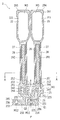
- FIG. 1 is a diagram showing the configuration of a tuning fork crystal resonator according to an embodiment of the present invention.
- the tuning fork crystal resonator element arranged on the tuning fork crystal resonator is cut along the line AA shown in FIG.
- FIG. 3 is a schematic cross-sectional view of a tuning-fork type crystal resonator at the time.
- FIG. 2 is a plan view of one main surface side of the tuning-fork type crystal vibrating piece showing the embodiment of the present invention.
- FIG. 3 is a plan view of the other main surface side of the tuning-fork type crystal vibrating piece showing the embodiment of the present invention.
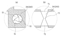
- FIG. 4 consists of FIG. 4A and FIG. 4B, and FIG.
- FIG. 4A is a schematic plan view of a through hole formed in a tuning fork type crystal vibrating piece showing an embodiment of the present invention.
- FIG. 4B is a schematic cross-sectional view thereof.
- FIG. 5 is an enlarged plan view in which the base of the tuning-fork type crystal vibrating piece shown in FIG. 2 is enlarged.
- the tuning fork type crystal resonator 1 used in the present embodiment includes a base 3 and a lid (not shown) joined via a sealing member H to form a casing.
- the tuning fork type crystal vibrating piece 2 is bonded to the electrode pad 32 of the base 3 having an opening at the top via a metal film M1 such as a plating bump, and the lid is bonded to the base 3 via the sealing member H.
- the storage part is hermetically sealed (see below).
- the nominal frequency of the tuning fork type crystal resonator 1 is 32.768 kHz. In addition, this nominal frequency is an example and can be applied to other frequencies.
- the base 3 is composed of an insulating container made of, for example, a ceramic material, a glass material, or a resin material.
- the base 3 has a bank portion 30 around it, and is formed in a concave shape in cross section with an upper opening, and a step portion for mounting the tuning fork type crystal vibrating piece 2 inside the base 3 (storage portion). 31 is formed.
- a pair of electrode pads 32 (only one of which is shown in FIG. 1) on which the tuning fork type crystal vibrating piece 2 is mounted is formed on the upper surface of the step portion 31.
- the pair of electrode pads 32 are electrically connected to two or more terminal electrodes 33 formed on the bottom surface (back surface) of the base 3 through a wiring pattern (not shown) formed inside the base 3.
- a metal film layer 34 (constituting a part of the sealing member H) is formed in a circumferential shape along the top surface.
- the electrode pad 32, the terminal electrode 33, and the metal film layer 34 are composed of, for example, a three-layered structure, and in the order of tungsten, nickel, and gold from the bottom. Are stacked. Tungsten is integrally formed during ceramic firing by metallization technology, and the nickel and gold layers are formed by plating technology. Note that molybdenum may be used for the tungsten layer.
- the lid (not shown) is made of, for example, a metal material, a ceramic material, or a glass material, and is formed into a single plate having a rectangular shape in plan view.
- a sealing material (constituting a part of the sealing member H) is formed on the lower surface of the lid.
- This lid is joined to the base 3 via the sealing material H by a technique such as seam welding, beam welding, heat fusion joining, etc., and the casing of the tuning fork type crystal resonator 1 is constituted by the lid and the base 3.
- the tuning fork type crystal vibrating piece 2 is a piezoelectric vibration element plate, and a large number of tuning fork type crystal vibrating pieces 2 are collectively formed from a single crystal wafer (not shown) made of a crystal Z plate made of anisotropic material.
- a resist or metal film is formed on a quartz wafer using photolithography technology, and the tuning-fork type quartz crystal is formed by wet etching, for example, using the resist or metal film formed on the quartz wafer as a mask.
- the resonator element 2 is formed with an outer shape.
- the tuning fork type crystal vibrating piece 2 includes a pair of first leg portions 21 and second leg portions 22 which are vibrating portions, and an external portion (in this embodiment, an electrode pad 32 of the base 3).
- a fork 253 is formed between the pair of first leg 21 and second leg 22 and at an intermediate position in the width direction of the one end face 251 of the base 25.
- connection electrodes 295 and 296 are formed which are lead-out end portions of the lead electrodes 293 and 294 and are formed at the joint portion 23 joined to the outside. . Further, part of the extraction electrodes 293 and 294 (the other end portions 297 and 298) are extracted to the fork portion 253 (including the vicinity of the fork portion 253).
- the through holes 241 and 242 are formed, and the lead electrodes 293 and 294 are routed using the through holes 241 and 242.
- the excitation electrodes 291 and 292 can be made wider and larger. As a result, the series resonance resistance value (CI value) can be reduced.
- the extraction electrodes 293 and 294 since it is not necessary to secure the design area of the lead pattern of the extraction electrodes 293 and 294 in the vicinity of the fork portion 253 (including the vicinity of the fork portion 253) of the tuning fork type crystal vibrating piece 2, the extraction electrodes 293 and 294 For the purpose of conduction, it is necessary to make the base plate shape of the fork portion 253, the base end portion 212 of the first leg portion 21 and the base end portion 222 of the second leg portion 22 into a tapered shape or an arc shape with a large R. Therefore, it is easy to cope with downsizing of the tuning fork type crystal vibrating piece 2.
- the base 25 has a symmetrical shape in plan view, and as shown in FIGS. 2 and 3, as shown in FIGS. 2 and 3, the vibration part (the first leg 21 (particularly the base end 212), the second leg 22 (particularly the base end 222)) (Refer to the above) Further, a step is gradually formed in the vicinity of the other end surface 252 of the base portion 25 so as to become narrower from the one end surface 251 to the other end surface 252. For this reason, the leakage vibration generated by the vibrations of the first leg portion 21 and the second leg portion 22 that are the vibration portions can be attenuated by the other end surface 252, and the transmission of the leakage vibration to the joint portion 23 can be suppressed.
- variety of the base 25 is narrow with respect to the one end surface 251 vicinity with the large width dimension of the base 25 on the basis of the planar view whole shape of the base 25.
- this portion is referred to as a constricted portion 255.
- the portion where the width of the base 25 is the narrowest in the constricted portion 255 is one end, and one end of the constricted portion 255 is the end of the base 25. This is a boundary (boundary point) between the other end face 252 and the joint 23, and is P3 shown in FIG.
- the constricted portion 255 is not limited to the step shape shown in FIGS. 2 and 3, and may be a tapered shape or a curved surface shape, or may be a combination of these shapes.
- a pair of through holes 241 and 242 are formed side by side along (in parallel with) the one end surface 251 on the one end surface 251 of the base portion 25.
- the pair of through holes 241 and 242 are positioned closer to the center line P (see FIGS. 2 and 3) in the width direction of the base portion 25 than base end portions 212 and 222 of a pair of leg portions 21 and 22 described later, and It is formed symmetrically with respect to the center line P in the width direction of the base 25 in a state where the mutual (mutual) through holes 241 and 242 do not contact each other.
- a line segment connecting a first joining region 235 described later and the center of the base end portion 212 of the leg portion 21 is defined as Q1, and the first joining region 235 and the leg portion 22 are connected to each other.
- a pair of through holes 241 and 242 are formed at positions on the line segments Q1 and Q2, where Q2 is a line segment connecting the center of the base end 222. For this reason, the propagation of vibration energy can be cut off more efficiently, and vibration leakage (acoustic leakage) can be suppressed even more efficiently.
- the through holes 241 and 242 are formed in the region where the extraction electrodes 293 and 294 are formed, and a conduction electrode (not shown) is formed inside the through holes 241 and 242.
- the conducting electrodes formed in the through holes 241 and 242 may be formed only on the wall surface S1 of the through holes 241 and 242 or may be formed in a state in which the through holes 241 and 242 are filled with the conducting electrodes. . With such a configuration of the through holes 241 and 242, the lead electrodes 293 and 294 formed on the one main surface 261 are led to the same lead electrode 293 and 294 on the other main surface 262, respectively.
- the inner wall surface of the through holes 241 and 242 is composed of a plurality of wall surfaces S1, and the wall surfaces inside the through holes 241 and 242 are formed by the plurality of wall surfaces S1. It is formed in a spiral shape. Further, in the through holes 241, 242, as shown in the cross-sectional view of FIG. 4 (b), the front and back main surfaces (one main surface 261 and the other main surface 262) of the tuning fork type crystal vibrating piece 2 are penetrated like an hourglass.
- the flat area of the through holes 241 and 242 (related to the opening diameter and opening width of the through holes 241 and 242) Opening area) to be reduced.
- Such a configuration of the through holes 241 and 242 is such that the temperature and concentration of the etching solution are not over-etched when the through holes 241 and 242 are formed by wet etching on an anisotropic crystal material such as quartz. Is optimally set, and the etching time is optimally managed.
- the stress from the outside is dispersed while gradually weakening along a plurality of wall surfaces S ⁇ b> 1 arranged (formed) in a spiral shape.
- the propagation of part of the vibration energy generated by the vibration of the first leg portion 21 and the second leg portion 22 that are the vibration portions is also released while gradually weakening along the spiral wall surfaces S1 of the through holes 241 and 242. be able to.
- the flat areas of the through holes 241 and 242 can be gradually reduced from both end portions T1 and T2 of the through holes 241 and 242 toward the inside T3 of the through holes 241 and 242, the surface areas of the through holes 241 and 242 are reduced. Can be increased, and the conduction state of the conduction electrode can be stabilized.
- the boundary point between the fork 253 and the vibrating portion (the base end 212 of the first leg 21 and the base end 222 of the second leg 22) is defined as a boundary point P1.
- the shortest point of the side surface 254 where the length from the boundary point P1 on the base 25 to the side surface 254 of the base 25 is the shortest is the shortest point P2, and the shortest length from the boundary point P1 to the shortest point P2 is the shortest length D1.
- the length connecting the boundary point P1 and the through holes 241 and 242 with the shortest length is defined as a length D2
- the length from the through holes 241 and 242 on the base 25 to the side surface 254 of the base 25 is the shortest side.
- the point 254 is the shortest point P3, the length connecting the through holes 241 and 242 and the shortest point P3 with the shortest length is the length D3, and the total shortest length is the sum of the length D2 and the length D3.
- the length is D4.
- the combined shortest length D4 is shorter than the shortest length D1.
- the vibration portion is the shortest length portion from the fork portion 253 to the side surface 254 of the base portion 25, and the shortest length from the fork portion 253 to the side surface 254 in the base portion 25 is from the shortest length D1.
- the first leg portion 21 and the second leg portion 22 vibrate around the portion on the combined shortest length D4. Therefore, when the shortest length is changed from the shortest length D1 to the combined shortest length D4, the stress caused by the vibration can be concentrated on the portion on the combined shortest length D4. As a result, the stress propagating to the joint portion 23 can be suppressed, and vibration leakage can be suppressed.
- the formation positions of the through holes 241 and 242 on the base 25 can be arbitrarily set as long as the relationship of the shortest length D1> the shortest length D4 is satisfied. It does not have to be arranged on a line passing through D4.
- the shortest point P3 where the length from the through holes 241 and 242 on the base 25 to the side surface 254 of the base 25 is the shortest is at one end of the constricted portion 255 as shown in FIG.
- One end of the constricted portion 255 is a portion having the narrowest width in the base portion 25.
- part on total shortest length D4 can be concentrated on the narrowest part among the narrow parts 255, As a result, it is preferable in reducing an acoustic leak (vibration leak) very effectively.
- the pair of first leg portions 21 and second leg portions 22 protrude from one end surface 251 of the base portion 25 and are arranged in parallel via the fork portion 253.
- the fork portion 253 here is provided at an intermediate position (central region) in the width direction of the one end surface 251 and refers to a region between two boundary points P1 (see FIG. 5).
- the distal end portions 211 and 221 and the proximal end portions 212 and 222 of the first leg portion 21 and the second leg portion 22 are in a protruding direction as compared with other portions of the first leg portion 21 and the second leg portion 22. Widely shaped in the orthogonal direction.
- the wide regions of the tip portions 211 and 221 of the first leg portion 21 and the second leg portion 22 are referred to as wide regions of the first leg portion 21 and the second leg portion 22.
- the corners of the tip portions 211 and 221 of the first leg portion 21 and the second leg portion 22 are curved.
- the tip portions 211 and 221 can be used effectively, which is useful for reducing the size of the tuning-fork type crystal vibrating piece 2 and has a low frequency. It is also useful for conversion.
- the corners of the tip portions 211 and 221 are not limited to curved surfaces, and may be tapered, or may be a shape combining curved surfaces and tapered corners.
- the one main surface 261 and the other main surface 262 of the pair of first leg portion 21 and second leg portion 22 have a series resonance resistance value (CI in the present embodiment) that deteriorates due to the downsizing of the tuning-fork type crystal vibrating piece 2.
- the groove portions 27 are respectively formed.
- a part of the side surface 28 of the outer shape of the tuning fork type crystal vibrating piece 2 is formed to be inclined with respect to the one main surface 261 and the other main surface 262. This is because the etching speed in the crystal direction (X, Y direction) of the substrate material is different when the tuning fork type crystal vibrating piece 2 is formed by wet etching.
- the joining portion 23 has an extraction electrode 293 and 294 described below as an external electrode (external in the present invention, in this embodiment, the electrode pads 32 and 32 of the base 3) and electromechanical. It is for joining. Specifically, the joint portion 23 is formed to project from an intermediate position (central region) in the width direction of the other end surface 252 facing the one end surface 251 of the base 25 from which the pair of first leg portions 21 and second leg portions 22 project. Has been. That is, the joint portion 23 is formed so as to protrude at a position facing the fork portion 253 disposed between the pair of first leg portions 21 and second leg portions 22.
- the joining portion 23 includes a short side portion 231 narrower than the other end surface 252 that protrudes in the vertical direction with respect to the other end surface 252 of the base portion 25, and a distal end portion of the short side portion 231.
- a long side portion 232 that is bent at a right angle in plan view at the distal end portion of the continuous short side portion 231 and extends in the width direction of the base portion 25, and the distal end portion 233 of the joint portion 23 faces the width direction of the base portion 25.
- the joining portion 23 is formed in an L shape in plan view, and a bent portion 234 that is a bent portion formed in an L shape in plan view corresponds to the tip portion of the short side portion 231.
- the short side part 231 is formed in a narrower state than the other end face 252 of the base part 25, the effect of further suppressing vibration leakage is enhanced.
- the main surface 261 of the joint portion 23 includes a first joint region 235 and a second joint region 236 that are joined to the outside, and the first joint region 235 extends in the width direction of the base portion 25. It is formed in one region of the bent portion 234 of the joint portion 23 formed in an L shape in plan view on the center line P on the extension line (intermediate position in the width direction of the short side portion 231 of the joint portion 23), The joining region 236 is formed in one region of the distal end portion of the long side portion 232 corresponding to the distal end portion 233 of the joining portion 23 formed in an L shape in plan view.
- connection electrode 296 leading end portion of the extraction electrode 294 drawn from an end portion (to one end portion) of the short side portion 231 through the extraction electrode 294 from a second excitation electrode 292 described later.
- connection electrode 295 extraction electrode extracted from the first excitation electrode 291 (described later) through the extraction electrode 293 to the end portion (tip end portion 233) of the long side portion 232 is formed in the second bonding region 236. 293 lead-out end).
- the first joint region 235 joined to the outside in the joint portion 23 can be electrically and mechanically joined as one pole at the bent portion 234 in which acoustic leakage is more efficiently suppressed.
- the second joining region 236 joined to the outside at 23 can be electromechanically joined as the other pole at the tip 233 that is not affected by acoustic leaks, stress or external force.
- metal films M1 are formed as plating bumps having a rougher surface roughness and a smaller flat area than the connection electrodes 295 and 296.
- the metal film M1 (M11, M12) is formed in a circular shape in plan view with a thickness of, for example, about 5 to 20 ⁇ m, a diameter of about 50 ⁇ m, and a plane area of about 1962.5 ⁇ m 2 .
- FCB ultrasonic bonding
- the thickness of the metal film M1 (M11, M12) When the thickness of the metal film M1 (M11, M12) is smaller than 5 ⁇ m, the gap between the connection electrodes 295, 296 of the tuning-fork type crystal vibrating piece 2 and the electrode pads 32, 32 of the base 3 becomes small, and the tuning-fork type crystal resonator 1 It tends to adversely affect the electrical characteristics of the.
- the thickness of the metal film M1 (M11, M12) is larger than 20 ⁇ m, the tuning fork type crystal vibrating piece 2 is likely to be influenced by the inclination and displacement, and the bonding strength is likely to vary.
- the planar shape of the metal film M1 (M11, M12) as the plating bump is a circular shape such as a circle or an ellipse, or a polygonal shape including a rectangle or a square, depending on the planar view shape of the connection electrode or the like. Things can be configured freely.
- the metal film formation part (connection electrodes 295, 296) (not shown) is formed in the first joint region 235 and the second joint region 236 of the joint 23.
- a mask having a window portion with a small plane area) is formed into a desired shape (rectangular window portion in this embodiment) by photolithography, and the metal film M1 (M11, M12) is formed on the formation portion of the metal film M1 (M11, M12).
- M11, M12) are plated by a technique such as electrolytic plating. Thereafter, an annealing treatment may be performed.
- the tuning fork type crystal vibrating piece 2 includes a pair of first excitation electrode 291 and second excitation electrode 292 configured with different potentials, and the first excitation electrode 291 and the second excitation electrode 292.
- Lead electrodes 293 and 294 drawn from the first and second excitation electrodes 291 and 292 to be electrically connected to the electrode pads 32 and 32, and a connection electrode 295 having a metal film M1 formed at the tip thereof , 296 are integrally formed simultaneously.
- the extraction electrodes 293 and 294 in the present embodiment refer to electrode patterns extracted from the pair of first excitation electrode 291 and second excitation electrode 292.
- the connection electrodes 295 and 296 indicate those formed at locations where the leading portions (leading end portions) of the extraction electrodes 293 and 294 are joined to the base 3.
- part of the pair of first excitation electrode 291 and second excitation electrode 292 is formed inside the groove 27. For this reason, even if the tuning fork type crystal vibrating piece 2 is downsized, the vibration loss of the first leg portion 21 and the second leg portion 22 is suppressed, and the CI value can be suppressed low.
- the first excitation electrode 291 is formed on both main surfaces (one main surface 261 and the other main surface 262) of the first leg portion 21 and both side surfaces 28 of the second leg portion 22.
- the second excitation electrode 292 is formed on both main surfaces (one main surface 261 and the other main surface 262) of the second leg portion 22 and both side surfaces 28 of the first leg portion 21.
- the first excitation electrode 291 and the second excitation electrode 292, the extraction electrodes 293 and 294, and the connection electrodes 295 and 296 of the tuning fork type crystal vibrating piece 2 are formed on the first leg portion 21 and the second leg portion 22 by metal deposition.
- the thin film is formed on the entire surface of the substrate by a technique such as vacuum vapor deposition or sputtering, and then formed into a desired shape by metal etching by photolithography.
- the first excitation electrode 291, the second excitation electrode 292, and the extraction electrodes 293, 294 are formed by laminating chromium (Cr) and gold (Au) in this order.
- chromium (Cr) For example, chromium (Cr), silver ( The order may be Ag), chromium (Cr), gold (Au), chromium (Cr), chromium (Cr), silver (Ag), chromium (Cr).
- first leg portion 21 and the second leg portion 22 are formed on the one main surface 261 and the other main surface 262 of the distal end portions 211 and 221 of the first leg portion 21 and the second leg portion 22.
- extraction electrodes 293 and 294 are formed on almost the entire surface.
- a metal film is formed on the upper surfaces of the extraction electrodes 293 and 294 formed in the wide regions of the first leg portion 21 and the second leg portion 22 of the one main surface 261 by ion irradiation such as laser beam irradiation or ion milling.
- the adjustment metal film (frequency adjustment weight) M3 obtained by adjusting the frequency of the tuning-fork type quartz vibrating piece 2 by reducing the mass of the tuning fork type crystal resonator element 2 is integrally formed with the extraction electrodes 293 and 294 in a slightly small area. .
- the adjustment metal film M3 is formed by forming a formation portion of the adjustment metal film M3 in a desired shape on the extraction electrodes 293 and 294 in each region (wide region) by photolithography.
- the adjustment metal film M3 is plated on the forming portion by a technique such as electrolytic plating. Thereafter, an annealing treatment may be performed.
- these metal films (adjustment metal film M3) are formed by plating, it is more practically desirable to form them simultaneously in the same process as the metal film M1 (M11, M12).
- the tuning-fork type crystal vibrating piece 2 configured as described above is measured after the frequency of each tuning-fork type crystal vibrating piece 2 is measured in the state of a wafer on which a large number of piezoelectric vibrating base plates are formed.
- the frequency is roughly adjusted by reducing the metal film M3 for adjustment of the crystal vibrating piece 2 by beam irradiation or by increasing it by partial vapor deposition.
- a piece of a tuning fork type crystal vibrating piece 2 (piezoelectric vibrating element plate) that has been subjected to coarse frequency adjustment and taken out of the wafer is a metal film M1 formed on the upper surface of the connection electrodes 295 and 296 on the one main surface 261 side. (M11, M12) and the electrode pads 32, 32 of the base 3 are ultrasonically bonded by the FCB method and mounted on the base 3.
- the tuning fork type quartz vibrating piece 2 mounted on the base 3 is finely adjusted by reducing the frequency of the frequency and then reducing the adjustment metal film M3 of the tuning fork type quartz vibrating piece 2 by beam irradiation or ion etching. The final frequency adjustment is performed.
- a lid (not shown) is joined to the base 3 on which the tuning-fork type crystal vibrating piece 2 having been subjected to the final frequency adjustment is mounted via a sealing member H by a technique such as heating and melting, and the tuning-fork type crystal.
- the resonator element 2 is hermetically sealed inside a housing constituted by a base 3 and a lid (not shown). Examples of the above-described hermetic sealing methods include seam welding, beam welding, and atmosphere heating.
- acoustic leak can be prevented more efficiently without hindering the downsizing of the tuning fork type crystal vibrating piece 2, and there is a problem that the tuning fork type crystal vibrating piece 2 is cracked by being strong against stress and external force. It can be prevented from occurring.
- it is possible to suppress vibration leakage (acoustic leakage) caused by vibration unbalance generated when exciting the tuning fork type crystal vibrating piece 2 without enlarging the length and area of the joint portion 23. Even when the tuning fork type crystal vibrating piece 2 is excited, vibration unbalance hardly occurs.
- the propagation of a part of vibration energy generated in the pair of first leg portion 21 and second leg portion 22 is also like an hourglass, and the inside of the piezoelectric vibration element plate ( Since the wall surface of the tuning fork-type crystal vibrating piece 2) is also combined with the spirally formed through holes 241 and 242 and can be cut off more efficiently, vibration leakage (acoustic leakage) is more efficiently performed. Therefore, it is possible to make the structure strong against stress and external force as a joint region with the outside.
- the front and back main surfaces via the ridge or side end surface of the tuning fork type crystal vibrating piece 2 around the fork portion 253 or the ridge portion or side end surface of the other base 25 adjacent to the fork portion 253. 261 and the other main surface 262) are not required to have a wiring structure for extending the extraction electrodes 293 and 294, and therefore, it is possible to achieve a configuration with stable electrical connectivity in which disconnection or the like hardly occurs. Further, a part of the extraction electrodes 293 and 294 is in contact with the fork portion 253 so as not to be drawn between the base end portion 212 and the base end portion 222 of the pair of leg portions (the first leg portion 21 and the second leg portion 22).
- the lead-out electrodes 293 and 294 formed on the main surface of the base portion 25 of the tuning-fork type crystal vibrating piece 2 can be easily designed with a more simplified wiring pattern, so that the tuning-fork type quartz crystal Miniaturization of the base 25 of the resonator element 2 can be realized at the same time.
- the tuning-fork type crystal vibrating piece 2 can be stably electromechanically joined to the base 3 by the metal film M1 (M11, M12).
- the tuning fork type crystal vibrating piece 2 can be used as a plating bump before the tuning fork type crystal vibrating piece 2 is mounted on the outside (base 3).
- Metal films M1 (M11, M12) can be formed.
- the metal film M1 (M11, M12) as a plating bump is always formed at a desired formation position of the tuning fork type crystal vibrating piece 2, for example, to the outside (base 3) of the tuning fork type crystal vibrating piece 2 Even if the mounting position is shifted from the desired position, it is possible to prevent the tuning-fork type crystal vibrating piece 2 from being mounted on the outside (base 3) in a state where the bump is shifted.
- the tuning-fork type crystal vibrating piece 2 can be mounted.
- the metal film M1 (M11, M12) having a rougher surface roughness and a smaller flat area than the connection electrodes 295, 296 is used, the metal film M1 (M11, M12) is more stable with respect to the electrode pads 32, 32. Thermal diffusion bonding is performed in a state, and electromechanical bonding is stabilized.
- the present invention can be applied to a piezoelectric vibration device such as a tuning fork type crystal resonator.
Landscapes
- Physics & Mathematics (AREA)
- Acoustics & Sound (AREA)
- Chemical & Material Sciences (AREA)
- Crystallography & Structural Chemistry (AREA)
- Engineering & Computer Science (AREA)
- Manufacturing & Machinery (AREA)
- Piezo-Electric Or Mechanical Vibrators, Or Delay Or Filter Circuits (AREA)
Abstract
Priority Applications (3)
| Application Number | Priority Date | Filing Date | Title |
|---|---|---|---|
| CN201280004036.6A CN103250349B (zh) | 2011-02-07 | 2012-02-02 | 音叉型压电振动片及音叉型压电振子 |
| US13/639,149 US8928208B2 (en) | 2011-02-07 | 2012-02-02 | Tuning fork-type piezoelectric resonator plate and tuning fork-type piezoelectric resonator |
| JP2012519809A JP5333668B2 (ja) | 2011-02-07 | 2012-02-02 | 音叉型圧電振動片、および音叉型圧電振動子 |
Applications Claiming Priority (2)
| Application Number | Priority Date | Filing Date | Title |
|---|---|---|---|
| JP2011024231 | 2011-02-07 | ||
| JP2011-024231 | 2011-02-07 |
Publications (1)
| Publication Number | Publication Date |
|---|---|
| WO2012108335A1 true WO2012108335A1 (fr) | 2012-08-16 |
Family
ID=46638551
Family Applications (1)
| Application Number | Title | Priority Date | Filing Date |
|---|---|---|---|
| PCT/JP2012/052425 Ceased WO2012108335A1 (fr) | 2011-02-07 | 2012-02-02 | Lame vibrante piézoélectrique de type diapason et vibrateur piézoélectrique de type diapason |
Country Status (4)
| Country | Link |
|---|---|
| US (1) | US8928208B2 (fr) |
| JP (1) | JP5333668B2 (fr) |
| CN (1) | CN103250349B (fr) |
| WO (1) | WO2012108335A1 (fr) |
Cited By (4)
| Publication number | Priority date | Publication date | Assignee | Title |
|---|---|---|---|---|
| WO2015072056A1 (fr) * | 2013-11-13 | 2015-05-21 | 株式会社大真空 | Plaquette piézoélectrique, pièce de vibration piézoélectrique et vibrateur piézoélectrique |
| JP2016149604A (ja) * | 2015-02-10 | 2016-08-18 | セイコーエプソン株式会社 | 振動子、発振器、リアルタイムクロック、電子機器、および移動体 |
| JP2017216753A (ja) * | 2017-09-15 | 2017-12-07 | セイコーエプソン株式会社 | 振動片、振動子、電子デバイス、電子機器、および移動体 |
| JP2023119229A (ja) * | 2022-02-16 | 2023-08-28 | 日本電波工業株式会社 | 水晶振動子及びその製造方法並びに水晶振動子用の中間体ウエハ |
Families Citing this family (7)
| Publication number | Priority date | Publication date | Assignee | Title |
|---|---|---|---|---|
| JP2015128268A (ja) * | 2013-12-27 | 2015-07-09 | セイコーエプソン株式会社 | 振動素子、振動子、発振器、電子機器、物理量センサー、移動体および振動素子の周波数調整方法 |
| JP6519995B2 (ja) * | 2014-06-30 | 2019-05-29 | セイコーエプソン株式会社 | 振動素子、振動素子の製造方法、振動子、ジャイロセンサー、電子機器および移動体 |
| JP6719178B2 (ja) * | 2015-05-22 | 2020-07-08 | エスアイアイ・クリスタルテクノロジー株式会社 | 圧電振動片の製造方法及び圧電振動子の製造方法 |
| US10110198B1 (en) * | 2015-12-17 | 2018-10-23 | Hrl Laboratories, Llc | Integrated quartz MEMS tuning fork resonator/oscillator |
| US11290082B2 (en) | 2017-03-30 | 2022-03-29 | Daishtnku Corporation | Tuning fork-type piezoelectric vibration piece and tuning fork-type piezoelectric vibrator using the vibration piece |
| CN111256673B (zh) * | 2020-01-19 | 2021-09-10 | 北京晨晶电子有限公司 | 一种石英音叉和基座的连接结构、连接方法及其应用 |
| JP7689421B2 (ja) * | 2020-11-30 | 2025-06-06 | エスアイアイ・クリスタルテクノロジー株式会社 | 圧電振動片の製造方法 |
Citations (5)
| Publication number | Priority date | Publication date | Assignee | Title |
|---|---|---|---|---|
| JP2004200914A (ja) * | 2002-12-17 | 2004-07-15 | Seiko Epson Corp | 圧電デバイス、及び圧電デバイスを利用した携帯電話装置、電子機器 |
| JP2006217603A (ja) * | 2006-01-30 | 2006-08-17 | Nippon Dempa Kogyo Co Ltd | 圧電振動子 |
| JP2008079014A (ja) * | 2006-09-21 | 2008-04-03 | Daishinku Corp | 音叉型圧電振動デバイス |
| WO2010035714A1 (fr) * | 2008-09-26 | 2010-04-01 | 株式会社大真空 | Elément vibrant piézoélectrique de type diapason et dispositif vibrant piézoélectrique de type diapason |
| JP2010178064A (ja) * | 2009-01-29 | 2010-08-12 | Daishinku Corp | 音叉型圧電振動片、および音叉型圧電振動デバイス |
Family Cites Families (3)
| Publication number | Priority date | Publication date | Assignee | Title |
|---|---|---|---|---|
| JP2011046581A (ja) * | 2009-08-28 | 2011-03-10 | Seiko Instruments Inc | 接合ガラスの切断方法、パッケージの製造方法、パッケージ、圧電振動子、発振器、電子機器及び電波時計 |
| US9130148B2 (en) * | 2011-02-25 | 2015-09-08 | Daishinku Corporation | Piezoelectric resonator plate, piezoelectric resonator, method for manufacturing piezoelectric resonator plate, and method for manufacturing piezoelectric resonator |
| JP2012205258A (ja) * | 2011-03-28 | 2012-10-22 | Seiko Instruments Inc | 研磨方法、圧電振動片の製造方法、圧電振動子、発振器、電子機器及び電波時計 |
-
2012
- 2012-02-02 WO PCT/JP2012/052425 patent/WO2012108335A1/fr not_active Ceased
- 2012-02-02 US US13/639,149 patent/US8928208B2/en active Active
- 2012-02-02 CN CN201280004036.6A patent/CN103250349B/zh active Active
- 2012-02-02 JP JP2012519809A patent/JP5333668B2/ja active Active
Patent Citations (5)
| Publication number | Priority date | Publication date | Assignee | Title |
|---|---|---|---|---|
| JP2004200914A (ja) * | 2002-12-17 | 2004-07-15 | Seiko Epson Corp | 圧電デバイス、及び圧電デバイスを利用した携帯電話装置、電子機器 |
| JP2006217603A (ja) * | 2006-01-30 | 2006-08-17 | Nippon Dempa Kogyo Co Ltd | 圧電振動子 |
| JP2008079014A (ja) * | 2006-09-21 | 2008-04-03 | Daishinku Corp | 音叉型圧電振動デバイス |
| WO2010035714A1 (fr) * | 2008-09-26 | 2010-04-01 | 株式会社大真空 | Elément vibrant piézoélectrique de type diapason et dispositif vibrant piézoélectrique de type diapason |
| JP2010178064A (ja) * | 2009-01-29 | 2010-08-12 | Daishinku Corp | 音叉型圧電振動片、および音叉型圧電振動デバイス |
Cited By (6)
| Publication number | Priority date | Publication date | Assignee | Title |
|---|---|---|---|---|
| WO2015072056A1 (fr) * | 2013-11-13 | 2015-05-21 | 株式会社大真空 | Plaquette piézoélectrique, pièce de vibration piézoélectrique et vibrateur piézoélectrique |
| US10211807B2 (en) | 2013-11-13 | 2019-02-19 | Daishinku Corporation | Piezoelectric wafer, piezoelectric vibration piece, and piezoelectric vibrator |
| JP2016149604A (ja) * | 2015-02-10 | 2016-08-18 | セイコーエプソン株式会社 | 振動子、発振器、リアルタイムクロック、電子機器、および移動体 |
| JP2017216753A (ja) * | 2017-09-15 | 2017-12-07 | セイコーエプソン株式会社 | 振動片、振動子、電子デバイス、電子機器、および移動体 |
| JP2023119229A (ja) * | 2022-02-16 | 2023-08-28 | 日本電波工業株式会社 | 水晶振動子及びその製造方法並びに水晶振動子用の中間体ウエハ |
| JP7799504B2 (ja) | 2022-02-16 | 2026-01-15 | 日本電波工業株式会社 | 水晶振動子及びその製造方法並びに水晶振動子用の中間体ウエハ |
Also Published As
| Publication number | Publication date |
|---|---|
| US20130020915A1 (en) | 2013-01-24 |
| CN103250349B (zh) | 2015-09-02 |
| JP5333668B2 (ja) | 2013-11-06 |
| JPWO2012108335A1 (ja) | 2014-07-03 |
| US8928208B2 (en) | 2015-01-06 |
| CN103250349A (zh) | 2013-08-14 |
Similar Documents
| Publication | Publication Date | Title |
|---|---|---|
| JP5333668B2 (ja) | 音叉型圧電振動片、および音叉型圧電振動子 | |
| JP5660162B2 (ja) | 音叉型圧電振動片、および音叉型圧電振動デバイス | |
| JP5218104B2 (ja) | 音叉型圧電振動片、および音叉型圧電振動デバイス | |
| JP5831353B2 (ja) | 音叉型圧電振動片、および音叉型圧電振動子 | |
| JP5146222B2 (ja) | 圧電振動デバイス | |
| CN105191124B (zh) | 音叉型压电振动片及音叉型压电振子 | |
| JP5397336B2 (ja) | 圧電振動片、および圧電振動子 | |
| JP6939876B2 (ja) | 音叉型圧電振動片および当該音叉型圧電振動片を用いた音叉型圧電振動子 | |
| JP2009296115A (ja) | 音叉型圧電振動片、音叉型圧電振動デバイス、および音叉型圧電振動片の製造方法 | |
| JP6011282B2 (ja) | 音叉型圧電振動片、及び音叉型圧電振動デバイス | |
| WO2011034104A1 (fr) | Élément piézoélectrique vibrant et son procédé de fabrication | |
| JP6179838B2 (ja) | 水晶振動子及び水晶振動デバイス | |
| JP5935664B2 (ja) | 音叉型圧電振動片、音叉型圧電振動デバイス、及び、音叉型圧電振動片の製造方法 | |
| JP4595913B2 (ja) | 音叉型圧電振動デバイス | |
| JP2009081670A (ja) | 圧電振動デバイス、およびその製造方法 | |
| JP2021068955A (ja) | 音叉型圧電振動片および当該音叉型圧電振動片を用いた音叉型圧電振動子 | |
| JP2014195133A (ja) | 圧電発振器 | |
| JP5637868B2 (ja) | 圧電デバイス及び圧電デバイスの製造方法 | |
| JP2014127895A (ja) | 音叉型圧電振動片、音叉型圧電振動子、および音叉型圧電振動片の製造方法 | |
| JP2018026723A (ja) | 音叉型圧電振動片および当該音叉型圧電振動片を用いた音叉型圧電振動子 | |
| JP5333806B2 (ja) | デバイス | |
| JP4935244B2 (ja) | 音叉型圧電振動片及び音叉型圧電振動デバイス | |
| JP2018037896A (ja) | 音叉型圧電振動片および当該音叉型圧電振動片を用いた音叉型圧電振動子 |
Legal Events
| Date | Code | Title | Description |
|---|---|---|---|
| WWE | Wipo information: entry into national phase |
Ref document number: 2012519809 Country of ref document: JP |
|
| 121 | Ep: the epo has been informed by wipo that ep was designated in this application |
Ref document number: 12744248 Country of ref document: EP Kind code of ref document: A1 |
|
| WWE | Wipo information: entry into national phase |
Ref document number: 13639149 Country of ref document: US |
|
| NENP | Non-entry into the national phase |
Ref country code: DE |
|
| 122 | Ep: pct application non-entry in european phase |
Ref document number: 12744248 Country of ref document: EP Kind code of ref document: A1 |