WO2012108500A1 - 可燃性ガス検出装置 - Google Patents
可燃性ガス検出装置 Download PDFInfo
- Publication number
- WO2012108500A1 WO2012108500A1 PCT/JP2012/052969 JP2012052969W WO2012108500A1 WO 2012108500 A1 WO2012108500 A1 WO 2012108500A1 JP 2012052969 W JP2012052969 W JP 2012052969W WO 2012108500 A1 WO2012108500 A1 WO 2012108500A1
- Authority
- WO
- WIPO (PCT)
- Prior art keywords
- temperature
- voltage
- heating resistor
- combustible gas
- gas detection
- Prior art date
- Legal status (The legal status is an assumption and is not a legal conclusion. Google has not performed a legal analysis and makes no representation as to the accuracy of the status listed.)
- Ceased
Links
Images


Classifications
-
- G—PHYSICS
- G01—MEASURING; TESTING
- G01N—INVESTIGATING OR ANALYSING MATERIALS BY DETERMINING THEIR CHEMICAL OR PHYSICAL PROPERTIES
- G01N25/00—Investigating or analyzing materials by the use of thermal means
- G01N25/18—Investigating or analyzing materials by the use of thermal means by investigating thermal conductivity
-
- G—PHYSICS
- G01—MEASURING; TESTING
- G01N—INVESTIGATING OR ANALYSING MATERIALS BY DETERMINING THEIR CHEMICAL OR PHYSICAL PROPERTIES
- G01N27/00—Investigating or analysing materials by the use of electric, electrochemical, or magnetic means
- G01N27/02—Investigating or analysing materials by the use of electric, electrochemical, or magnetic means by investigating impedance
- G01N27/04—Investigating or analysing materials by the use of electric, electrochemical, or magnetic means by investigating impedance by investigating resistance
- G01N27/14—Investigating or analysing materials by the use of electric, electrochemical, or magnetic means by investigating impedance by investigating resistance of an electrically-heated body in dependence upon change of temperature
- G01N27/18—Investigating or analysing materials by the use of electric, electrochemical, or magnetic means by investigating impedance by investigating resistance of an electrically-heated body in dependence upon change of temperature caused by changes in the thermal conductivity of a surrounding material to be tested
-
- H—ELECTRICITY
- H01—ELECTRIC ELEMENTS
- H01M—PROCESSES OR MEANS, e.g. BATTERIES, FOR THE DIRECT CONVERSION OF CHEMICAL ENERGY INTO ELECTRICAL ENERGY
- H01M8/00—Fuel cells; Manufacture thereof
- H01M8/04—Auxiliary arrangements, e.g. for control of pressure or for circulation of fluids
- H01M8/04298—Processes for controlling fuel cells or fuel cell systems
- H01M8/04313—Processes for controlling fuel cells or fuel cell systems characterised by the detection or assessment of variables; characterised by the detection or assessment of failure or abnormal function
- H01M8/0444—Concentration; Density
- H01M8/04447—Concentration; Density of anode reactants at the inlet or inside the fuel cell
-
- H—ELECTRICITY
- H01—ELECTRIC ELEMENTS
- H01M—PROCESSES OR MEANS, e.g. BATTERIES, FOR THE DIRECT CONVERSION OF CHEMICAL ENERGY INTO ELECTRICAL ENERGY
- H01M2250/00—Fuel cells for particular applications; Specific features of fuel cell system
- H01M2250/20—Fuel cells in motive systems, e.g. vehicle, ship, plane
-
- Y—GENERAL TAGGING OF NEW TECHNOLOGICAL DEVELOPMENTS; GENERAL TAGGING OF CROSS-SECTIONAL TECHNOLOGIES SPANNING OVER SEVERAL SECTIONS OF THE IPC; TECHNICAL SUBJECTS COVERED BY FORMER USPC CROSS-REFERENCE ART COLLECTIONS [XRACs] AND DIGESTS
- Y02—TECHNOLOGIES OR APPLICATIONS FOR MITIGATION OR ADAPTATION AGAINST CLIMATE CHANGE
- Y02E—REDUCTION OF GREENHOUSE GAS [GHG] EMISSIONS, RELATED TO ENERGY GENERATION, TRANSMISSION OR DISTRIBUTION
- Y02E60/00—Enabling technologies; Technologies with a potential or indirect contribution to GHG emissions mitigation
- Y02E60/30—Hydrogen technology
- Y02E60/50—Fuel cells
-
- Y—GENERAL TAGGING OF NEW TECHNOLOGICAL DEVELOPMENTS; GENERAL TAGGING OF CROSS-SECTIONAL TECHNOLOGIES SPANNING OVER SEVERAL SECTIONS OF THE IPC; TECHNICAL SUBJECTS COVERED BY FORMER USPC CROSS-REFERENCE ART COLLECTIONS [XRACs] AND DIGESTS
- Y02—TECHNOLOGIES OR APPLICATIONS FOR MITIGATION OR ADAPTATION AGAINST CLIMATE CHANGE
- Y02T—CLIMATE CHANGE MITIGATION TECHNOLOGIES RELATED TO TRANSPORTATION
- Y02T90/00—Enabling technologies or technologies with a potential or indirect contribution to GHG emissions mitigation
- Y02T90/40—Application of hydrogen technology to transportation, e.g. using fuel cells
Definitions
- the present invention relates to a flammable gas detection device that detects the gas concentration of a flammable gas present in a detection atmosphere.
- PEFCs solid polymer fuel cells
- hydrogen internal combustion engines are expected as energy sources for home use and on-vehicle use due to advantages such as low temperature operation and high output density.
- the resistance value of the heating resistor in the gas detection element is set to each resistance value corresponding to two set temperatures (first set temperature and second set temperature).
- the gas concentration is calculated using the control voltage (voltage across the heating resistor) at that time and the voltage difference (temperature voltage) generated by changing the resistance value of the resistance temperature detector. ing.
- Each set temperature (the first set temperature and the second set temperature) is, for example, selectively switching the conduction state of fixed resistors having different resistance values installed in the bridge circuit at regular cycle times. (See, for example, Patent Document 1).
- the present invention desirably provides a combustible gas detection device capable of suppressing a decrease in gas concentration detection accuracy. Furthermore, it is desirable to provide a combustible gas detection device capable of accurately detecting the gas concentration.
- the combustible gas detection device is a heating resistor that is arranged in a detection atmosphere and changes its resistance value due to its own temperature change, and two set temperatures in which the heating resistor is preset. And an energization control unit that performs control to switch the energization state of the heating resistor at regular cycle times so that each resistance value corresponds to each of the resistance values, and the atmosphere to be detected is disposed on the same substrate as the heating resistor And a resistance temperature detector whose resistance value changes due to a change in environmental temperature, which is the internal temperature.
- the gas concentration calculation unit changes the voltage across the heating resistor detected when the heating resistor is energized under the control of the energization control unit and the resistance value of the resistance temperature detector.
- the concentration of combustible gas in the detected atmosphere is calculated using the environmental temperature based on the voltage difference (temperature voltage) generated by the above.
- the period time is set in advance to a time during which the change in the environmental temperature caused by the energization control unit switching the energization state of the heating resistor is within the range of 0.5 ° C. ing.
- the heating temperature (setting of the heating resistor) is set.
- the gas concentration detection error can be kept within a tolerance range, and the deterioration of the gas concentration detection accuracy of the combustible gas can be suppressed.
- the high temperature side is the first set temperature and the low temperature side is the second set temperature
- the first set temperature and the second set temperature are Two preset temperatures are set in advance at a temperature at which the temperature difference of 50 ° C. or more.
- the gas concentration calculation unit sets the voltage at both ends of the heating resistor detected at the first set temperature as the high temperature voltage and the voltage at both ends of the heating resistor detected at the second set temperature as the low temperature voltage. Based on the ratio between the voltage and the low temperature voltage, the humidity in the atmosphere to be detected is calculated, and the concentration of the combustible gas is corrected using the humidity.
- the combustible gas detection device configured in this way, it is possible to ensure high resolution in the ratio of the high temperature voltage and the low temperature voltage, so that the humidity in the detected atmosphere can be accurately calculated. As a result of correction using this, the concentration of combustible gas can be detected with high accuracy.
- the combustible gas detection device of the present invention is a gas detection element formed by micromachining using a silicon substrate, and the heating resistor and the resistance temperature detector are arranged on the same silicon substrate.
- the gas detection element formed by micromachining using a silicon substrate is very small, and when a heating resistor and a resistance temperature detector are disposed on such a silicon substrate, Both will be in close proximity.
- the heating temperature (set temperature) of the heating resistor is switched before the error increases between the environmental temperature based on the temperature voltage of the resistance temperature detector and the actual environmental temperature. As a result, the effect of keeping the detection error of the gas concentration within the allowable range is favorably achieved.
- the combustible gas detection device provides at least one environmental temperature based on the resistance value of the resistance temperature detector in each of two consecutive cycles among the cycles switched by the energization control unit.
- An average value calculation unit that detects the average value of a plurality of environmental temperatures detected during two consecutive periods is provided.
- the gas concentration calculation part in this combustible gas detection apparatus uses the average value of the environmental temperature calculated by the average value calculation part for calculation of the density
- the combustible gas detector configured in this way detects the ambient temperature in each of two consecutive cycles and calculates the average value thereof, so that either one of the two set temperatures of the heating resistor is set. Compared to the case where the ambient temperature is detected only in the corresponding cycle, the ambient temperature can be detected in a state in which the effect of the difference in the amount of heat generated by the heating resistor due to switching of the energized state is reflected on the resistance temperature detector. Therefore, the detection accuracy of the environmental temperature can be improved.
- the detection of the combustible gas concentration caused by the fluctuation A decrease in accuracy can be suppressed.
- the cycle time is set within the range of 25 [mSec] to 1 [Sec].
- the process proceeds to the next cycle before the time from when the energization state of the heating resistor is switched until the temperature of the heating resistor stabilizes ( In other words, there is a possibility that the switching time of the energized state will come), and there is a possibility that the voltage across the heating resistor corresponding to each set temperature cannot be detected properly.
- the combustible gas detection device of the present invention it is possible to appropriately detect the voltage across the heating resistor in a state where the temperature of the heating resistor is stable, and to suppress a decrease in the followability to a change in gas concentration. , A decrease in gas concentration detection accuracy can be suppressed.
- the substrate is formed in a square shape (substantially square shape) in a plan view, and the heating resistor is measured by the substrate in a state in which the substrate is viewed in a plan view.
- the resistance temperature detector is arranged on the center side of the resistor, and the resistance temperature detector is arranged in a region along at least two connected sides among the four sides forming the edge of the substrate.
- the combustible gas detection device configured as described above it is possible to secure a relatively wide arrangement region of the resistance temperature detector, and thus the resistance value of the desired range can be obtained for the length of the resistance temperature detector. It becomes easy to design to a desired length, and the degree of design freedom can be improved.
- the resistance temperature detector when it is necessary to increase the length of the resistance temperature detector, a portion of the resistance temperature detector that is close to the heating resistor is required in order to reduce the size of the substrate. Therefore, the resistance temperature detector becomes more susceptible to the heat effect of the heating resistor. For this reason, the gas concentration detection apparatus according to the first aspect of the present invention can be applied more effectively.
- the resistance temperature detector is disposed in a region along the three sides of the edge of the substrate.
- the degree of freedom in design can be further improved.
- similar to a heating resistor in a temperature measuring resistor may become still larger, a temperature measuring resistor becomes still more susceptible to the heat influence of a heating resistor, and by extension, combustibility of the 1st aspect of this invention
- the gas detection device can be applied more effectively.
- the two electrodes connected to both ends of the heating resistor are the first electrode group, and the two electrodes connected to both ends of the resistance temperature detector are the first.
- the first electrode group and the second electrode group are arranged in a region along one side of the edge of the substrate.
- the combustible gas detection device configured as described above, since the connection between the heating resistor and the resistance temperature detector and the input / output circuit unit provided outside the substrate becomes easy, the wiring structure can be simplified. As a result, the entire apparatus can be reduced in size.
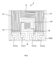
- FIG. 2A is a plan view showing a configuration of a gas detection element that is a main part of the combustible gas detection device
- FIG. 2B is a cross-sectional view of the gas detection element taken along line IIB-IIB in FIG. 2A.
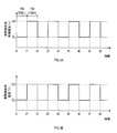
- 4A is a time chart showing the voltage across the heating resistor
- FIG. 4B is a time chart showing the temperature of the heating resistor
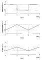
- 5A is a time chart of the temperature of the heating resistor
- FIG. 5B is a time chart of the temperature output of the resistance temperature detector
- FIG. 5C is a time chart of the output error.
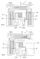
- FIG. 7A is a second schematic diagram illustrating the arrangement of each part of the gas detection element
- FIG. 7B is a third schematic diagram illustrating the arrangement of each part of the gas detection element. It is a flowchart which shows the content of the voltage detection process in 2nd Embodiment. It is a flowchart which shows the content of the gas concentration calculating process in 2nd Embodiment.
- SYMBOLS 1 Combustible gas detection apparatus, 3 ... Gas detection element, 5 ... Control circuit, 7 ... Microcomputer, 8 ... Memory
- storage device 34 ... Starting switch, 34 ... Heating resistor, 35 ... Resistance temperature detector, 50 ... Current control Circuit, 51 ... Bridge circuit, 52 ... Variable resistance section, 55 ... Current adjustment circuit, 57 ... Switching circuit, 80 ... Temperature adjustment circuit, 81 ... Bridge circuit, 87 ... Switching circuit, 521, 522 ... Fixed resistance, 523 ... Switching Switch, CH ... first set temperature, CL ... second set temperature, TW ... cycle time.
- FIG. 1 is an overall configuration diagram of a combustible gas detection device 1 to which the present invention is applied.
- FIG. 2A is a plan view showing the configuration of the gas detection element 3 which is the main part of the combustible gas detection device 1 (however, the internal configuration is also partially shown), and FIG. 2B is taken along the line IIB-IIB in FIG. 2A. It is sectional drawing of the gas detection element.
- the combustible gas detection device 1 detects the concentration of combustible gas using a heat-conducting gas detection element 3, and is installed in a passenger room of a fuel cell vehicle, for example, to detect hydrogen leakage. Used for purposes.
- the combustible gas detection device 1 generates a control circuit 5 that drives and controls the gas detection element 3 (see FIGS. 2A and 2B), and a switching signal CG1 that controls the operation of the control circuit 5.
- the microcomputer executes at least various processes including a process (gas concentration calculation process) for calculating the gas concentration of the combustible gas contained in the detected gas based on the detection signals V1 and SVT obtained from the control circuit 5. (Hereinafter referred to as “microcomputer”) 7, and a control circuit 5 and a start switch 9 for starting and stopping the microcomputer 7 by turning on and off the power supply path from the DC power supply Vcc to the combustible gas detection device 1. Yes.
- the control circuit 5 (except for a heating resistor 34 and a temperature measuring resistor 35, which will be described later), the microcomputer 7 and the start switch 9 are configured on a single circuit board, and a gas separate from this circuit board.
- the detection element 3 is configured.
- the gas detection element 3 includes a base 30 having a flat plate shape (square shape in plan view), and a plurality of electrodes 31 are provided on one surface (hereinafter referred to as “surface”) of the base 30.
- surface one surface of the base 30.
- back surface one recess 301 is formed in the vicinity of the center of the base 30 along one direction of the base 30.
- the gas detection element 3 has a size of about several mm (for example, 3 mm ⁇ 3 mm) in both vertical and horizontal directions, and is manufactured by, for example, a micromachining technique (micromachining process) using a silicon substrate.
- a micromachining technique micromachining process
- the electrode 31 includes two electrodes (electrode pads) 311 and 312 (hereinafter also referred to as “first electrode group”) arranged along one side of the base 30 (the lower side in FIG. 2A), and the other And two electrodes (electrode pads) 314 and 315 (hereinafter also referred to as “second electrode group”) arranged along the side (the upper side in FIG. 2A).
- first electrode group two electrodes (electrode pads) 311 and 312
- first electrode group” arranged along one side of the base 30 (the lower side in FIG. 2A)
- second electrodes electrodes 314 and 315
- the electrodes 312 and 315 are also referred to as ground electrodes below.
- money (Au) is used, for example.
- the base 30 includes a silicon substrate 32 and an insulating layer 33 formed on one surface of the substrate 32, and the insulating layer 33 is partially (here, substantially square) exposed so that the substrate 32 is exposed.
- a diaphragm structure in which a recess 301 is formed by removing a part is formed. That is, in the base portion 30, the insulating layer 33 side (the side where the substrate 32 is not removed) is the surface of the base portion 30, and the substrate 32 side (including the side where a part of the substrate 32 is removed) is the back surface of the base portion 30. It becomes.
- a linear heating resistor 34 wired in a spiral shape is embedded in a portion exposed on the back surface of the base 30 by the recess 301, and the side on which the second electrode groups 314 and 315 are formed.
- a resistance temperature detector 35 used for temperature measurement is embedded along the long side (one side) of the base 30.
- the heating resistor 34 is arranged in a region closer to the center than the resistance temperature detector 35 in the insulating layer 33, and the resistance temperature detector 35 extends along one of the four sides forming the edge of the insulating layer 33. Is located in the area.
- the insulating layer 33 may be formed of a single material, or may be formed of a plurality of layers using different materials. Further, as the insulating material constituting the insulating layer 33, for example, silicon oxide (SiO 2) or silicon nitride (Si 3 N 4) is used.
- the heating resistor 34 is made of a conductive material having a large temperature resistance coefficient whose resistance value changes according to its own temperature change, and the resistance temperature detector 35 has an electrical resistance that changes in proportion to the temperature (this embodiment). Then, it is comprised with the electroconductive material which resistance value increases with a rise in temperature. However, the heating resistor 34 and the temperature measuring resistor 35 are both made of the same resistance material, platinum (Pt) in this embodiment.
- the heating resistor 34 is connected to the first electrode group 311, 312 via a wiring 36 and a wiring film 37 embedded in the same plane as the heating resistor 34 is formed, and the resistance thermometer 35. Are connected to the second electrode groups 314 and 315 via a wiring film (not shown) embedded in the same plane as that on which the resistance temperature detector 35 is formed.
- the same resistance material as that of the heating resistor 34 and the temperature measuring resistor 35 is used as the material constituting the wiring 36 and the wiring film 37. Further, the electrode 31 formed on the surface of the base 30 and the wiring film 37 formed inside the base 30 (insulating layer 33) are connected by a contact hole (connection conductor).
- one end of the heating resistor 34 is connected to the electrode 311 and the other end is connected to the ground electrode 312, and the resistance temperature detector 35 is connected so that one end is connected to the electrode 314 and the other end is connected to the ground electrode 315. .
- the gas detection element 3 configured as described above is used in a state where the back surface on which the concave portion 301 is formed is disposed so as to be exposed to the atmosphere to be detected.
- Control circuit Next, the configuration of the control circuit 5 will be described.
- control circuit 5 controls the energization of the heating resistor 34 and outputs a detection signal V 1 corresponding to the voltage across the heating resistor 34, and the resistance temperature detector 35. And a temperature adjustment circuit 80 that outputs a temperature detection signal SVT representing the temperature of the atmosphere to be detected.
- the energization control circuit 50 includes a bridge circuit (Wheatstone bridge circuit) 51 configured to include the heating resistor 34, an amplifier circuit 53 that amplifies the potential difference detected by the bridge circuit 51, and an output of the amplifier circuit 53. And a current adjustment circuit 55 that adjusts the current flowing through the circuit 51 to increase or decrease.
- a bridge circuit Woodstone bridge circuit
- the energization control circuit 50 includes a bridge circuit (Wheatstone bridge circuit) 51 configured to include the heating resistor 34, an amplifier circuit 53 that amplifies the potential difference detected by the bridge circuit 51, and an output of the amplifier circuit 53.
- a current adjustment circuit 55 that adjusts the current flowing through the circuit 51 to increase or decrease.
- the current adjustment circuit 55 includes a transistor that is connected to a power supply line that supplies the DC power supply Vcc to the bridge circuit 51 and whose energization state (ON resistance) changes according to the adjustment signal C that is an output of the amplification circuit 53. Specifically, as the adjustment signal C is larger, the on-resistance is increased and the current flowing through the bridge circuit 51 is decreased. Conversely, as the adjustment signal is smaller, the on-resistance is decreased and flows through the bridge circuit 51. The current is configured to increase.
- the amplifier circuit 53 is connected in parallel between the operational amplifier 531, fixed resistors 532 and 533 connected to the inverting input terminal and the non-inverting input terminal of the operational amplifier 531, and the inverting input terminal and output terminal of the operational amplifier 531.
- a well-known differential amplifier circuit including a fixed resistor 534 and a capacitor 535 connected to each other is provided.
- the adjustment signal C that is the output of the amplifier circuit 53 increases (and the current flowing through the bridge circuit 51 decreases), and conversely.
- the adjustment signal C is reduced (and the current flowing through the bridge circuit 51 is increased).
- the bridge circuit 51 includes a heating resistor 34, two fixed resistors 511, 512, and a variable resistor 52 that can switch a resistance value.
- the fixed resistor 511, the heating resistor 34, the fixed resistor 512, and the variable resistor 52 are connected in series, and in each series circuit, the heating resistor 34 and each end PG on the variable resistor 52 side are grounded, and each end on the fixed resistors 511 and 512 side is connected to the power source side (current adjustment circuit 55). ) Is connected to.
- connection point P + between the fixed resistor 511 and the heating resistor 34 is connected to the non-inverting input terminal of the operational amplifier 531 through the fixed resistor 532, and the connection point P ⁇ between the fixed resistor 512 and the variable resistor unit 52 is Are connected to the inverting input terminal of the operational amplifier 531 through the fixed resistor 533. Further, the potential at the connection point P + is supplied to the microcomputer 7 as the detection signal V1.
- the variable resistance unit 52 includes two fixed resistors 521 and 522 having different resistance values, and a changeover switch 523 that effectively operates one of the fixed resistors 521 and 522 in accordance with the changeover signal CG1 from the microcomputer 7.
- the balance of the bridge circuit 51 can be changed by switching the resistance value of the variable resistance unit 52 with the changeover switch 523.
- the fixed resistor 521 has a resistance value at which the heating resistor 34 becomes a first set temperature CH (for example, 400 ° C.), and the fixed resistor 522 is set so that the heating resistor 34 is lower than the first set temperature CH.
- the resistance value is a second set temperature CL (for example, 300 ° C.).
- the energization control circuit 50 configured as described above, when energization from the DC power supply Vcc to the bridge circuit 51 is started, the potential difference generated between the connection points P + and P ⁇ in the amplifier circuit 53 and the current adjustment circuit 55 becomes zero. Thus, the current flowing through the bridge circuit 51 is adjusted. As a result, the resistance value (and hence the temperature) of the heating resistor 34 is controlled to a constant value (and thus the first set temperature CH or the second set temperature CL) determined by the variable resistance unit 52.
- the resistance value of the heating resistor 34 decreases. Conversely, when the amount of heat taken away by the combustible gas is smaller than the amount of heat generated by the heating resistor, the temperature of the heating resistor 34 rises, and the resistance value of the heating resistor 34 increases.
- the amplifier circuit 53 and the current adjusting circuit 55 increase the current flowing through the bridge circuit 51 and thus the amount of heat generated by the heat generating resistor 34.
- the resistance value of the resistor 34 increases, the current flowing through the bridge circuit 51, and hence the amount of heat generated by the heating resistor 34, is reduced, so that the resistance value (and thus the temperature) of the heating resistor 34 is kept constant. .
- the magnitude of the current flowing through the heating resistor 34 that is, the amount of heat necessary for keeping the temperature (resistance value) of the heating resistor 34 constant (and further, , The amount of heat taken away by the combustible gas), and the amount of heat has a magnitude corresponding to the gas concentration, so that the gas concentration of the combustible gas can be determined from the detection signal V1.
- correction is performed using the humidity H in the atmosphere to be detected. This will be described in “gas concentration calculation processing” described later.
- the temperature adjustment circuit 80 includes a bridge circuit (Wheatstone bridge) 81 configured to include the resistance temperature detector 35 and an amplifier circuit 83 that amplifies the potential difference obtained from the bridge circuit 81.
- a bridge circuit Woodstone bridge
- the amplifier circuit 83 is connected in parallel between the operational amplifier 831, fixed resistors 832 and 833 connected to the inverting input terminal and the non-inverting input terminal of the operational amplifier 831, and the inverting input terminal and output terminal of the operational amplifier 831.
- a well-known differential amplifier circuit including a fixed resistor 834 and a capacitor 835 connected thereto is provided.
- the bridge circuit 81 includes a resistance temperature detector 35 and three fixed resistors 811, 812, and 813.
- the fixed resistor 811 and the resistance temperature detector 35, and the fixed resistor 812 and the fixed resistor 813 are connected in series, respectively. Of the series circuit, each end on the resistance temperature detector 35 and the fixed resistor 813 side is grounded, and each end on the fixed resistors 811 and 812 side is connected to a power source.
- connection point P ⁇ between the fixed resistor 811 and the resistance temperature detector 35 is connected to the inverting input terminal of the operational amplifier 531 via the fixed resistor 833, and the connection point P + between the fixed resistor 812 and the fixed resistor 813 is connected to the fixed resistor. It is connected to the non-inverting input terminal of the operational amplifier 831 through 832.
- the output of the operational amplifier 831 is supplied to the microcomputer as a temperature detection signal SVT.
- the resistance temperature detector 35 is set so that the temperature detection signal SVT becomes a reference value when the temperature of the detected atmosphere to which the gas detection element 3 is exposed is a preset reference temperature. Then, as the temperature of the atmosphere to be detected changes, the resistance value of the resistance temperature detector 35 changes to produce a potential difference, and the amplified potential difference is output as the temperature detection signal SVT.
- the electrode 31 (311, 312, 314, 315) of the gas detection element 3 is connected to the connection point P + of the energization control circuit 50 and the electrode 314 is connected to the electrode 311.
- Ground electrodes 312 and 315 are connected to a common ground line for the control circuit 5 at a connection point P ⁇ of the temperature adjustment circuit 80.
- the microcomputer 7 includes a storage device 8 (ROM, RAM, etc.) for storing various programs and data for executing gas concentration calculation processing, a CPU for executing the program stored in the storage device 8, and various signals.
- ROM read-only memory
- RAM random access memory
- This is a well-known device including an IO port for output, a timer for timekeeping, and the like.
- the signal level of the detection signal V1 detected at the first set temperature CH (400 ° C.) is the high temperature voltage VH1
- the signal level of the detection signal V1 detected at the second set temperature CL (300 ° C.) is the low temperature.
- the signal level of the temperature detection signal SVT read from the hour voltage VL1 and the temperature adjustment circuit 80 is referred to as a temperature voltage VT.
- the storage device 8 includes temperature conversion data representing the correlation between the environmental temperature T and the temperature voltage VT in the detected atmosphere, the humidity H and the high temperature voltage VH1, the low temperature voltage VL1, and the temperature voltage in the detected atmosphere.
- Humidity conversion data representing the correlation with VT, high-temperature voltage VH1 or low-temperature voltage VL1 (in this embodiment, high-temperature voltage VH1 is used) and concentration-conversion data representing the correlation between combustible gas concentration X
- Each conversion data is specifically composed of conversion map data, a calculation formula for conversion, and the like, and is created in advance based on data obtained through experiments or the like.
- the humidity conversion data includes voltage ratio conversion map data representing a correlation between the environmental temperature T (and thus the temperature voltage VT) and a voltage ratio VC (0) described later, and a voltage ratio difference ⁇ VC and humidity H described below.
- Humidity conversion map data representing the correlation is included.
- the concentration conversion data includes high temperature voltage conversion map data representing a correlation between the temperature voltage VT and a high temperature voltage VH1 (0) described later, a high temperature voltage VH1 and a humidity H, and a high temperature voltage change ⁇ VH1 described below.
- H includes humidity voltage change conversion map data, temperature voltage VT and high temperature voltage VH1, and gas sensitivity conversion map data indicating a correlation between gas sensitivity G (VT) described later. Yes.
- microcomputer 7 is activated when power supply is started from the DC power supply Vcc by turning on the activation switch 9, and after initializing each part of the microcomputer 7, the gas concentration calculation process is started.
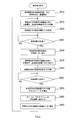
- the gas concentration calculation process executed by the CPU of the microcomputer 7 will be described with reference to the flowchart shown in FIG.
- the gas concentration X is obtained from the low-temperature voltage VL1 or the high-temperature voltage VH1 using the concentration conversion data, and further, the environmental temperature is calculated from the temperature voltage VT using the temperature conversion data.
- the gas concentration X is calculated using the humidity H in addition to the environmental temperature T.
- the resistance value of the bridge circuit 51 that is, the set temperature of the heating resistor 34 is set to the second set temperature for a certain cycle time TW (hereinafter also referred to as “low temperature measurement period TWL”) by the switching signal CG1.
- TW cycle time
- the setting is switched, and control for holding at the first set temperature CH is performed again for a certain period of time TW (hereinafter also referred to as “high temperature measurement period TWH”) (see FIGS. 4A-4B).
- the low-temperature voltage VL1 is detected during the low-temperature measurement period
- the high-temperature voltage VH1 is detected during the high-temperature measurement period
- the temperature voltage VT is detected at any timing in both periods.
- 4A is a time chart showing the voltage across the heating resistor
- FIG. 4B is a time chart showing the temperature of the heating resistor.
- the voltage ratio VC is calculated using the low temperature voltage VL1 and the high temperature voltage VH1 acquired in S110 as input values of the following equation (1).
- VC VH1 / VL1 (1)
- the gas concentration X and the humidity H at the environmental temperature T are obtained.
- the voltage ratio VC (0) when is zero is calculated.
- the voltage ratio difference VC in the ambient temperature T (and thus the temperature voltage VT) is obtained by using the voltage ratio VC calculated in S120 and the VC (0) calculated in S130 as input values of the following equation (2). Is calculated.
- the high temperature voltage VH1 obtained in S110, the humidity H calculated in S150, and the humidity voltage change conversion map data are provided by the humidity H of the high temperature voltage VH1.
- a high-temperature voltage change ⁇ VH1 (H) that represents the voltage change is calculated.
- the high-temperature voltage VH1 acquired in S110, the high-temperature voltage VH1 (0) calculated in S160, and the high-temperature voltage change ⁇ VH1 (H) calculated in S170 are expressed by the following equation (3).
- a high-temperature voltage change ⁇ VH1 (G) representing a voltage change caused by the combustible gas in the high-temperature voltage VH1 is calculated.
- ⁇ VH1 (G) VH1 ⁇ VH1 (0) ⁇ VH1 (H) (3)
- the environmental temperature T and thus the temperature voltage VT for the high-temperature voltage VH1.
- Gas sensitivity G (VT) representing the sensitivity (in units of the reciprocal of the gas concentration X) for the combustible gas set in advance.
- the gas concentration of the combustible gas is obtained by using the high-temperature voltage change ⁇ VH1 (G) calculated in S180 and the gas sensitivity G (VT) calculated in S190 as input values of the following equation (4).
- X is calculated, and the process returns to S110.
- the changeover signal CG1 is output to the changeover switch 523 every cycle time TW, so that the connection point P ⁇ between the fixed resistor 512 and the variable resistor unit 52 is connected to the end PG (in the variable resistor unit 52).
- the energization path (the energization path in the variable resistance section 52) to the ground side end) is switched from one side to the other side of the fixed resistances 521 and 522, whereby the high temperature voltage VH1, the low temperature voltage VL1, and the temperature voltage. Get VT.
- the environmental temperature T is calculated based on the temperature voltage VT, and further, the humidity H in the detected atmosphere is calculated from the ratio of the high temperature voltage VH1 and the low temperature voltage VL1, and these environmental temperatures are calculated.
- the gas concentration X is corrected using T and humidity H.
- 400 degreeC is employ
- 300 degreeC is employ
- the voltage at both ends of the heating resistor 34 is set to the low temperature voltage VL1.
- the reason why the difference between the first set temperature CH and the second set temperature CL (set temperature difference) is 100 ° C. is that the set temperature difference is 50 ° C. or more in order to accurately calculate the humidity H in the detected atmosphere. This is because it is necessary to ensure high resolution in the ratio between the high temperature voltage VH1 and the low temperature voltage VL1.
- the upper limit of the set temperature difference may be set to 200 ° C. or less in consideration of the durability of the gas detection element 3, and the set temperature difference is preferably set within a range of 75 ° C. to 150 ° C. do it.
- the resistance temperature detector 35 is prevented from being affected as much as possible by the change in the heat generation temperature (and hence the set temperature difference) by the heat generation resistor 34. It is preferable.
- the heat generating resistor 34 and the temperature measuring resistor 35 are embedded (arranged) in the insulating layer 33 on the substrate 32 while being formed by micromachining using a silicon substrate 32.
- the heating resistor 34 and the temperature measuring resistor 35 are disposed close to each other.
- the cycle time TW for holding (switching) the first and second set temperatures (CH, CL) is necessary for the output of the detection signal V1 to be sufficiently stable after switching these set temperatures. Although it needs to be longer than the time, it must be set so that the detection error based on the set temperature difference of the heating resistor 34 when detecting the gas concentration X falls within a preset tolerance range.
- This detection error is assumed when the temperature measuring resistor 35 is not affected by the set temperature difference of the heating resistor 34 due to switching of the set temperature, that is, the environmental temperature T is set to a constant temperature (reference temperature).
- the gas concentration X calculated when the gas is fixed is set as a reference concentration, and the gas concentration X considering the variation of the environmental temperature T is ⁇ 5% F.S. S. If it is within (full scale), it is considered to be within the tolerance.
- FIGS. 5A, 5B, and 5C are explanatory diagrams showing simulation results for setting the cycle time.
- FIG. 5A is a time chart of the temperature of the heating resistor
- FIG. 5B is the temperature of the resistance temperature detector
- FIG. 5C is an output time chart
- FIG. 5C is an output error time chart.
- the cycle time TW under the condition that the environmental temperature T (reference temperature) is 25 ° C. when the set temperature of the heating resistor 34 is 300 ° C. was temporarily set to 5 s, and the correlation between the output change of the resistance temperature detector 35 when the above program was executed and the output error (detection error) with respect to the reference concentration of the gas concentration X as the calculation result was obtained.
- the change signal CG1 to the changeover switch 523 every cycle time TW (5 s)
- the high temperature voltage VH1, the low temperature voltage VL1, and the temperature voltage VT are acquired, and the environmental temperature T is obtained from the temperature voltage VT.
- the gas concentration X was calculated by calculating the humidity H in the atmosphere to be detected from the ratio of the high temperature voltage VH1 and the low temperature voltage VL1 and correcting using the environmental temperature T and humidity H.
- the time change of the environmental temperature T and the gas concentration X corresponding to the reference temperature (25 ° C.) were used as the reference concentration, and the time change of the output error with respect to the reference concentration of the gas concentration X as the calculation result was obtained as the simulation result.
- the set temperature difference of the heating resistor 34 is 100 ° C., but the resolution in the ratio between the high temperature voltage VH1 and the low temperature voltage VL1 is further increased (in other words, the humidity H in the detected atmosphere H Is detected with higher accuracy), it is considered that the set temperature difference should be further increased.
- the resistance temperature detector 35 is more easily affected by the change in the heat generation temperature due to the heat generation resistor 34, and therefore it is necessary to further shorten the cycle time TW.
- the cycle time TW is set to 200 ms so as to withstand various reference temperatures.
- the change in the environmental temperature T caused by the change in the heat generation temperature of the heat generation resistor 34 is 0.
- the output error of the gas concentration X is ⁇ 5% F.S. S. It was possible to fit in.
- the heating resistor 34 before the error increases between the environmental temperature T based on the temperature voltage VT of the resistance temperature detector 35 and the actual environmental temperature.
- the exothermic temperature set temperature
- the combustible gas detection device 1 calculates the humidity H from the high temperature voltage VH1 and the low temperature voltage VL1 and the environmental temperature T from the temperature voltage VT in the gas concentration calculation process, and calculates the humidity H and the environmental temperature T. Since the gas concentration X in the detected atmosphere calculated based on the high-temperature voltage VH1 is calculated (corrected), the gas concentration X of the combustible gas can be determined with high accuracy.
- the combustible gas detection device 1 since the first set temperature CH and the second set temperature CL are set in advance so that the set temperature difference of the heating resistor 34 is 100 ° C., the high temperature voltage VH1. Since the high resolution in the ratio between the low temperature voltage VL1 and the low temperature voltage VL1 can be ensured, the humidity H in the atmosphere to be detected can be calculated with high accuracy. As a result of correction using this, the gas concentration X of the combustible gas Can be detected with higher accuracy.
- the microcomputer 7 that outputs the energization control circuit 50 and the switching signal CG1 corresponds to an example of an energization control unit
- the microcomputer 7 that executes the gas concentration calculation process corresponds to an example of a gas concentration calculation unit.
- the first set temperature CH and the second set temperature CL are set in advance so that the set temperature difference of the heating resistor 34 becomes 100 ° C.
- the set temperature difference may be 50 ° C. or more.
- the set temperature difference is preferably in the range of 50 ° C. to 150 ° C.
- the cycle time TW is set to 200 ms in advance.
- the cycle time TW is not limited to this, and the cycle time TW is an environmental temperature generated by a change in the heat generation temperature of the heating resistor 34. What is necessary is just the time when the amount of change in T falls within the range of 0.5 ° C.
- the gas concentration X is calculated using the humidity H in the detected atmosphere.
- the present invention is not limited to this, and at least the heating resistor 34 is used.
- the gas concentration X may be calculated using the both-end voltage (VH1, VL1) and the temperature voltage VT of the resistance temperature detector 35.
- the resistance temperature sensor 35 is arrange
- the resistance temperature detector 35 has a region (heating resistance) along the three sides at the edge of the insulating layer 33 in a state where the gas detection element 3 is viewed in plan.
- the region surrounding the body 34) may be arranged.
- the first electrode group 311, 312 and the second electrode group 314, 315 are arranged along the sides facing each other on the surface of the base 30.
- the first electrode group 311, 312 and the second electrode group 314, 315 are arranged in a region along the same side of the edge of the surface of the base 30. May be.
- each part in the gas detection element 3 shown in FIG. 6 it is possible to secure a wider arrangement region of the resistance temperature detector 35 as compared with the above embodiment. It is easy to design the length so as to obtain a resistance value in a desired range, the degree of design freedom can be further improved, and the temperature detection accuracy can be increased.
- the portion of the temperature measuring resistor 35 that is close to the heating resistor 34 (wiring 36) is larger than that of the above embodiment, and the temperature measuring resistor 35 is more susceptible to the thermal influence of the heating resistor 34. Become. For this reason, according to this arrangement configuration, it is possible to further enjoy the effect of shortening the cycle time TW for switching the set temperature of the heating resistor 34 in the gas concentration calculation processing executed by the microcomputer 7 in the above embodiment.
- an input / output circuit part (for example, provided outside the gas detection element 3 with the first electrode groups 311 and 312, the second electrode groups 314 and 315) Since the connection with the circuit board becomes easy, the wiring structure can be simplified, and as a result, the combustible gas detection device 1 as a whole can be reduced in size.
- each part in the gas detection element 3 is not limited to the configuration illustrated in FIG. 6.
- the first electrode groups 311 and 312 and the second electrode groups 314 and 315 are arranged on the base 30.
- the resistance temperature detector 35 is arranged in a region along the three sides of the edge on the base 30 (region surrounding the heating resistor 34 and the first electrode group 311, 312). May be.
- each part in the gas detection element 3 is a region along the two sides where the resistance temperature detector 35 is connected at the edge on the base 30 (the heating resistor 34 and the first electrode). It may be arranged in a region surrounding the groups 311 and 312.
- the distance between the heating resistor 34 and the temperature measurement resistor 35 when the gas detection element 3 is viewed in plan is, for example, 0 in the gas detection element 3 shown in FIG. 2A. .6 [mm] is set.
- the gas detection element 3 having such a configuration can appropriately detect the temperature in the vicinity of the heating resistor 34 with the temperature measuring resistor 35.
- the heating resistor 34 and the resistance temperature detector 35 are both provided inside the insulating layer 33, but the arrangement position of the insulating layer 33 in the thickness direction may not necessarily be the same. However, since the insulating layer 33 is a thin film and its thickness dimension is small, the actual distance between the heating resistor 34 and the temperature measuring resistor 35 is the heating resistor 34 when the gas detection element 3 is viewed in plan view. And the temperature measuring resistor 35.
- the distance between the heating resistor 34 and the temperature measuring resistor 35 is the distance between the heating wire constituting the heating resistor 34 and the heating wire constituting the temperature measuring resistor 35, and the wiring connected to each heating wire (Lead part) Not the distance between them.
- the distance between the heating resistor 34 and the resistance temperature detector 35 when the gas detection element 3 is viewed in a plan view is not limited to 0.6 [mm], and may be 1.0 [mm] or less. Good. By adopting such a configuration, the temperature measuring resistor 35 can appropriately detect the temperature in the vicinity of the heating resistor 34.
- the configuration in which the temperature voltage VT is detected at any one of the low temperature measurement period TWL and the high temperature measurement period TWH has been described.
- the temperature voltage VT is detected at both the low temperature measurement period and the high temperature measurement period. It may be.
- the temperature voltage VT (in other words, the environmental temperature T) is detected in each of two consecutive cycles (low temperature measurement period and high temperature measurement period), and the temperature voltage that is an average value of them is detected.
- a combustible gas detector that calculates the average value VTav will be described.
- the combustible gas detection device of the second embodiment differs from the combustible gas detection device 1 of the above embodiment mainly in part of the processing executed by the microcomputer 7, but the other configurations are as follows. It is the same composition. Therefore, in the following description, it demonstrates centering on a different part and description of the content similar to 1st Embodiment is abbreviate
- the microcomputer 7 provided in the combustible gas detection device of the second embodiment is activated when power supply is started from the DC power supply Vcc by turning on the activation switch 9, and after initializing each part of the microcomputer 7 The voltage detection process and the gas concentration calculation process are started.
- the energization state of the heating resistor 34 is set to the low temperature side control state, and specifically, the heating resistor in the bridge circuit 51 is switched by switching the resistance value of the variable resistor unit 52 by the switching signal CG1.
- the set temperature 34 is set to the second set temperature CL (300 ° C.).
- the temperature voltage VT (hereinafter also referred to as the low temperature temperature voltage VTL) at the time of low temperature measurement of the heating resistor 34 (in other words, at the time of setting the second set temperature CL) is acquired.
- the voltage across the heating resistor 34 (hereinafter also referred to as the low temperature voltage VL1) at the time of low temperature measurement of the heating resistor 34 (in other words, when the second set temperature CL is set) is acquired.
- S830 a process of switching the energization state of the heating resistor 34 to the high temperature side control state is performed. Specifically, the set temperature of the heating resistor 34 in the bridge circuit 51 is set to the first set temperature CH (400 ° C.) by switching the resistance value of the variable resistor unit 52 by the switching signal CG1.
- a temperature voltage VT (hereinafter also referred to as a high temperature temperature voltage VTH) at the time of measuring the heating resistor 34 at a high temperature (in other words, at the time of setting the first set temperature CH) is acquired.
- VTH a temperature voltage VT
- VH1 the voltage across the heating resistor 34
- the high temperature voltage VH1 when the heating resistor 34 is measured at a high temperature (in other words, when the first set temperature CH is set) is acquired.
- an average value of the temperature voltage VT (hereinafter also referred to as a temperature voltage average value VTav) is calculated in S850.
- the low temperature voltage VL1 acquired in S820, the high temperature voltage VH1 acquired in S840, and the temperature voltage average value VTav calculated in S845 are stored in the storage device 8 (memory, RAM, etc.) of the microcomputer 7. Perform the process.
- the set temperature of the heating resistor 34 in the bridge circuit 51 is set to the second set temperature CL (300 ° C.) by switching the resistance value of the variable resistor section 52 by the switching signal CG1.
- the process in S860 ends, the process proceeds to S815 again, and then the processes from S815 to S860 are repeatedly executed until the voltage detection process is stopped.
- the set temperature of the heating resistor 34 of the bridge circuit 51 is set to the second setting for a certain period of time TW (hereinafter also referred to as “low temperature measurement period TWL”).
- TW a certain period of time
- the set temperature of the heating resistor 34 is switched to the first set temperature CH.
- the set temperature of the heating resistor 34 is held at the first set temperature CH, and after the high temperature measurement period TWH has ended, the heating resistance Control for switching the set temperature of the body 34 to the second set temperature CL is performed (see FIGS. 4A and 4B).
- the temperature voltage VTL at the low temperature and the temperature voltage VTH at the high temperature are detected, and the temperature voltage average value VTav which is an average value thereof is calculated.
- the energization state of the heating resistor is switched every fixed period time TW, and each of the low temperature voltage VL1, the high temperature voltage VH1, and the temperature voltage average value VTav is changed to the microcomputer 7
- the process of saving in the storage device 8 (memory, RAM, etc.) is executed.
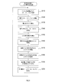
- FIG. 9 is a flowchart showing the contents of the gas concentration calculation process in the second embodiment.
- the gas concentration calculation process of the second embodiment differs from the gas concentration calculation process of the first embodiment shown in FIG. 3 at least in the processing contents in S110, S130, S160, and S190.
- each of “low temperature voltage VL1, high temperature voltage VH1, and temperature voltage average value VTav” is stored. Get the latest value. That is, in S ⁇ b> 110 of the second embodiment, the information stored in the storage device 8 is acquired instead of acquiring each information directly from the energization control circuit 50 and the temperature adjustment circuit 80.
- the gas concentration calculation processing in the second embodiment differs from the first embodiment in that the temperature voltage VT is replaced with the temperature voltage VT.
- Each calculation process is executed using the voltage average value VTav. That is, in S130, S160, and S190 of the second embodiment, each calculation process is executed using the temperature voltage average value VTav.
- the gas concentration calculation process of the second embodiment first, “low temperature voltage VL1, high temperature voltage VH1, temperature stored in the storage device 8 (memory, RAM, etc.) of the microcomputer 7 by the voltage detection process. Each latest value of “average voltage value VTav” is acquired.
- the environmental temperature T is calculated based on the temperature voltage average value VTav, and further, the humidity H in the detected atmosphere is calculated from the ratio of the high temperature voltage VH1 and the low temperature voltage VL1, The gas concentration X is corrected using the environmental temperature T and the humidity H.
- the changeover switch 523 of the energization control circuit 50 is switched based on the switching signal CG1 from the microcomputer 7, so that the temperature is lowered every certain measurement period TW.
- the cycle corresponding to the measurement period TWL and the cycle corresponding to the high temperature measurement period TWH are switched (S825, S830, S845, S860).
- the temperature voltage VT (specifically, the low temperature temperature voltage VTL and the high temperature temperature voltage VTH) is detected in each of two consecutive cycles among the cycles corresponding to the low temperature measurement period TWL and the high temperature measurement period TWH.
- the temperature voltage VT (in other words, the environmental temperature T) can be detected in a state in which the influence of the difference in the amount of heat generated by the heating resistor 34 due to the switching of the energized state on the temperature measuring resistor 35 is reflected.
- the amount of heat generated by the heat generating resistor 34 when the first set temperature CH is set depends on the temperature measuring resistor.
- the effect on the temperature sensing resistor 35 is different from the effect on the temperature measuring resistor 35 when the second set temperature CL is set. That is, when the temperature voltage VT (in other words, the environmental temperature T) is detected only in the cycle corresponding to one of the two set temperatures, the heat generation of the heating resistor 34 is performed in the cycle corresponding to the other set temperature.
- the temperature voltage VT (in other words, the environmental temperature T) is detected in a state where the influence of the quantity on the resistance temperature detector 35 is not reflected.
- the temperature voltage VT (in other words, the environmental temperature T) is detected in each of two successive cycles, and the temperature voltage average value VTav that is an average value thereof is detected. Is calculated, and the temperature voltage VT (in other words, the environmental temperature T) is detected in a state in which the influence of the difference in the amount of heat generated by the heating resistor 34 due to the switching of the energized state on the temperature measuring resistor 35 is reflected. Therefore, the detection accuracy of the environmental temperature T can be improved.
- a temperature voltage average value VTav environmental temperature average value which is an average value of the temperature voltage VT (in other words, the environmental temperature T)
- the resistance temperature detector is influenced by sudden noise or the like. Even if the numerical value of the temperature voltage VT (in other words, the environmental temperature T) based on 35 varies, it is possible to suppress a decrease in the detection accuracy of the combustible gas concentration caused by the variation.
- the microcomputer 7 that executes the energization control circuit 50 and the voltage detection processes S810, S825, S830, S845, and S860 corresponds to an example of an energization control unit, and the microcomputer 7 that executes the voltage detection process and the gas concentration calculation process performs the gas concentration calculation.
- the microcomputer 7 that executes S815, S835, and S850 of the voltage detection process corresponds to an example of an average value calculation unit.
- the present invention is not limited to the second embodiment, and can be implemented in various modes without departing from the gist of the present invention. It is.
- the detection frequency of the temperature voltage VT is not limited to once per one period (period time TW) as in the second embodiment. It may be twice or more per cycle (cycle time TW).
- the temperature voltage VT low temperature voltage VTL or high temperature voltage VTH
- all detected temperature voltages VT low temperature voltage VTL
- the average value of the high temperature temperature voltage VTH is calculated as the temperature voltage average value VTav (environmental temperature average value).
- the cycle time TW is not limited to the numerical values of the first embodiment and the second embodiment, and may be set within a range of 25 [mSec] to 1 [Sec]. That is, when the cycle time TW is shorter than 25 [mSec], the next cycle is started before the time until the temperature of the heating resistor 34 is stabilized after the energization state of the heating resistor 34 is switched. There is a possibility of transition (in other words, the switching time of the energized state comes). In such a case, the voltage across the heating resistor 34 (high temperature voltage VH1, low temperature voltage VL1) corresponding to each set temperature (first set temperature CH, second set temperature CL) may not be detected properly. There is.
- the switching interval of the energization state of the heating resistor 34 becomes longer, and each corresponds to two set temperatures (first set temperature CH and second set temperature CL).
- the detection interval of the voltage across the heating resistor 34 increases. In such a case, the followability to the change in gas concentration is lowered, and there is a possibility that the detection accuracy of the gas concentration is lowered.
- the cycle time TW is set within the range of 25 [mSec] to 1 [Sec]
- the voltage across the heating resistor 34 with the temperature of the heating resistor 34 stabilized.
- the device for storing various programs and data for executing each process in the microcomputer 7 is not limited to the storage device 8 provided in the microcomputer 7, and information is transmitted between the microcomputer 7.
- any form of external storage device or recording medium that can be used.
- the microcomputer 7 executes each process using various programs and data read from the external storage device or the recording medium.
- the recording medium include a portable semiconductor memory (for example, a USB memory, a memory card (registered trademark)), an optical disk such as a CD-ROM or a DVD, a magnetic disk, and the like.
Landscapes
- Chemical & Material Sciences (AREA)
- Life Sciences & Earth Sciences (AREA)
- Chemical Kinetics & Catalysis (AREA)
- Electrochemistry (AREA)
- Biochemistry (AREA)
- Pathology (AREA)
- Immunology (AREA)
- General Physics & Mathematics (AREA)
- General Health & Medical Sciences (AREA)
- Physics & Mathematics (AREA)
- Health & Medical Sciences (AREA)
- Analytical Chemistry (AREA)
- Sustainable Energy (AREA)
- General Chemical & Material Sciences (AREA)
- Sustainable Development (AREA)
- Manufacturing & Machinery (AREA)
- Engineering & Computer Science (AREA)
- Investigating Or Analyzing Materials By The Use Of Electric Means (AREA)
- Investigating Or Analyzing Materials Using Thermal Means (AREA)
Abstract
Description
この種の被検出雰囲気中に存在する可燃性ガスのガス濃度を検出する可燃性ガス検出装置では、被検出雰囲気内にガス検出素子を配置し、このガス検出素子に、自身の温度変化(発熱)により抵抗値が変化する発熱抵抗体と、環境温度の変化により抵抗値が変化する測温抵抗体とを実装するものが知られている。
また、本発明の第4局面の可燃性ガス検出装置は、周期時間が25[mSec]~1[Sec]の範囲内に設定されている。
図1は、本発明が適用された可燃性ガス検出装置1の全体構成図である。図2Aは、可燃性ガス検出装置1の主要部となるガス検出素子3の構成を示す平面図(但し、内部構成も一部示す)であり、図2Bが図2AにおけるIIB-IIB線に沿ったガス検出素子の断面図である。
可燃性ガス検出装置1は、熱伝導式のガス検出素子3を用いて、可燃性ガスの濃度を検出するものであり、例えば、燃料電池自動車の客室内に設置され、水素の漏れを検出する目的等に用いられる。
次に、ガス検出素子3について説明する。
図2A,図2Bに示すように、ガス検出素子3は、平板形状(平面視四角形状)の基部30を備え、基部30の一方の面(以下「表面」という)には、複数の電極31が形成され、他方の面(以下「裏面」という)には、基部30の中心付近に、基部30の一方の方向に沿って一つの凹部301が形成されている。
[制御回路]
次に、制御回路5の構成について説明する。
通電制御回路50は、発熱抵抗体34を含んで構成されたブリッジ回路(ホイートストンブリッジ回路)51と、ブリッジ回路51で検出される電位差を増幅する増幅回路53と、増幅回路53の出力に従って、ブリッジ回路51に流れる電流を増減調整する電流調整回路55とを備えている。
次に、温度調整回路80は、測温抵抗体35を含んで構成されたブリッジ回路(ホイートストンブリッジ)81と、ブリッジ回路81から得られる電位差を増幅する増幅回路83とを備えている。
そして、被検出雰囲気の温度変化に伴って、測温抵抗体35の抵抗値が変化することにより電位差が生じ、この電位差を増幅したものが温度検出信号SVTとして出力される。
マイコン7は、ガス濃度演算処理等を実行するための各種のプログラムやデータを格納する記憶装置8(ROM,RAM等)、この記憶装置8に記憶されたプログラムを実行するCPU、各種信号を入出力するためのIOポート、計時用タイマー等を備えた周知のものである。
ここで、マイコン7のCPUが実行するガス濃度演算処理を、図3に示すフローチャートに沿って説明する。なお、ガス濃度Xを求める演算では、低温時電圧VL1または高温時電圧VH1のいずれかから濃度換算データを用いてガス濃度Xを求め、さらには、温度電圧VTから温度換算データを用いて環境温度Tを求め、演算結果であるガス濃度Xを、同じく演算結果である環境温度Tだけを用いて補正する方法もあるが、ここでは、環境温度Tに加えて湿度Hを用いてガス濃度Xを求めるものとする。
VC=VH1/VL1…(1)
また、これと並行して、S130では、S110にて取得した温度電圧VTと、電圧比換算用マップデータとに基づいて、環境温度T(ひいては温度電圧VT)においてガス濃度X、及び、湿度Hがゼロのときの電圧比VC(0)を算出する。
次に、S150では、S140にて算出した電圧比差ΔVCと、湿度換算用マップデータとに基づいて、電圧比差ΔVCのときの湿度Hを算出する。
また、これと並行して、S190では、S110にて取得した高温時電圧VH1,温度電圧VTと、ガス感度換算用マップデータとに基づいて、高温時電圧VH1について環境温度T(ひいては温度電圧VT)毎に予め設定された可燃性ガスに対する感度(単位はガス濃度Xの逆数)を表すガス感度G(VT)を算出する。
このように、本処理では、周期時間TW毎に切替信号CG1を切替スイッチ523に出力することにより、固定抵抗512と可変抵抗部52との接続点P-から端部PG(可変抵抗部52における接地側端部)への通電経路(可変抵抗部52における通電経路)を、固定抵抗521,522のいずれか一方側から他方側に切り替え、これにより高温時電圧VH1,低温時電圧VL1,温度電圧VTを取得する。そして、ガス濃度演算処理では、温度電圧VTに基づいて環境温度Tを演算し、さらには、高温時電圧VH1と低温時電圧VL1の比から被検出雰囲気内の湿度Hを演算し、これら環境温度Tと湿度Hとを用いてガス濃度Xを補正する。
以上、説明したように、本実施形態の可燃性ガス検出装置1では、周期時間TWについて、発熱抵抗体34の発熱温度の変化(ひいては設定温度差)によって生じる環境温度Tの変化分が0.5℃の範囲内となる時間に予め設定しておくことにより、ガス濃度Xの出力誤差が±5%F.S.に収まることを可能とした。
ここで、特許請求の範囲と本実施形態とにおける文言の対応関係について説明する。通電制御回路50および切替信号CG1を出力するマイコン7が通電制御部の一例に相当し、ガス濃度演算処理を実行するマイコン7がガス濃度演算部の一例に相当する。
以上、本発明の実施形態について説明したが、本発明は上記実施形態に限定されるものではなく、本発明の要旨を逸脱しない範囲において、様々な態様にて実施することが可能である。
図8に示す電圧検出処理が実行されると、まず、S810では、発熱抵抗体34および測温抵抗体35への通電を開始する。
続くS820では、発熱抵抗体34の低温測定時(換言すれば、第2設定温度CLの設定時)における発熱抵抗体34の両端電圧(以下、低温時電圧VL1ともいう)を取得する。
具体的には、切替信号CG1により可変抵抗部52の抵抗値を切り替えることで、ブリッジ回路51における発熱抵抗体34の設定温度を第1設定温度CH(400℃)に設定する。
続くS840では、発熱抵抗体34の高温測定時(換言すれば、第1設定温度CHの設定時)における発熱抵抗体34の両端電圧(以下、高温時電圧VH1ともいう)を取得する。
具体的には、S815で取得した低温時温度電圧VTLとS835で取得した高温時温度電圧VTHとの平均値を、温度電圧平均値VTav(=(VTL+VTH)/2)として算出する。
このようにして電圧検出処理を実行することで、まずは、一定の周期時間TWの間(以下「低温測定期間TWL」ともいう)は、ブリッジ回路51の発熱抵抗体34の設定温度を第2設定温度CLに保持し、低温測定期間TWLが終了した後、発熱抵抗体34の設定温度を第1設定温度CHに切り替える。その後、一定の周期時間TWの間(以下「高温測定期間TWH」ともいう)は、発熱抵抗体34の設定温度を第1設定温度CHに保持し、高温測定期間TWHが終了した後、発熱抵抗体34の設定温度を第2設定温度CLに切り替える制御を行う(図4A、図4B参照)。
図9は、第2実施形態におけるガス濃度演算処理の内容を示すフローチャートである。
第2実施形態のガス濃度演算処理は、図3に示す第1実施形態のガス濃度演算処理と比べて、少なくともS110,S130,S160,S190での処理内容が異なる。
ここで、特許請求の範囲と本第2実施形態とにおける文言の対応関係について説明する。通電制御回路50および電圧検出処理のS810,S825,S830,S845,S860を実行するマイコン7が通電制御部の一例に相当し、電圧検出処理およびガス濃度演算処理を実行するマイコン7がガス濃度演算部の一例に相当し、電圧検出処理のS815,S835,S850を実行するマイコン7が平均値算出部の一例に相当する。
つまり、周期時間TWが25[mSec]よりも短い場合には、発熱抵抗体34の通電状態の切り替え時点から発熱抵抗体34の温度が安定するまでの時間が経過する前に、次の周期に移行する(換言すれば、通電状態の切り替え時期が到来する)可能性がある。このような場合には、各設定温度(第1設定温度CH、第2設定温度CL)に応じた発熱抵抗体34の両端電圧(高温時電圧VH1,低温時電圧VL1)を適切に検出できないおそれがある。
Claims (7)
- 可燃性ガス検出装置であって、
被検出雰囲気内に配置されて、自身の温度変化により抵抗値が変化する発熱抵抗体と、
前記発熱抵抗体が予め設定された二つの設定温度にそれぞれ対応する各抵抗値となるように、該発熱抵抗体の通電状態を一定の周期時間毎に切り替える制御を行う通電制御部と、
前記発熱抵抗体と同一の基板上に配置されて、前記被検出雰囲気内の温度である環境温度の変化により抵抗値が変化する測温抵抗体と、
前記通電制御部の制御による前記発熱抵抗体への通電時に検出される該発熱抵抗体の両端電圧と、前記測温抵抗体の抵抗値が変化することにより生じる電圧変化に基づく環境温度とを用いて、前記被検出雰囲気内の可燃性ガスの濃度を演算するガス濃度演算部と、
を備え、
前記周期時間は、前記通電制御部が前記発熱抵抗体の通電状態を切り替えることによって生じる前記環境温度の変化分が0.5℃の範囲内となる時間に予め設定されている、
という可燃性ガス検出装置。 - 請求項1に記載の可燃性ガス検出装置であって、
前記二つの設定温度は、当該設定温度のうち高温側を第1設定温度、低温側を第2設定温度とし、前記第1設定温度と前記第2設定温度との温度差が50℃以上となる温度に予め設定されており、
前記ガス濃度演算部は、前記第1設定温度時に検出される前記発熱抵抗体の両端電圧を高温時電圧、前記第2設定温度時に検出される前記発熱抵抗体の両端電圧を低温時電圧とし、該高温時電圧と該低温時電圧との比に基づいて、前記被検出雰囲気内の湿度を算出し、該湿度を用いて前記可燃性ガスの濃度を補正する、
という可燃性ガス検出装置。 - 請求項1または請求項2に記載の可燃性ガス検出装置であって、
前記通電制御部により切り替えられる各周期のうち連続する二つの周期のそれぞれにおいて、前記測温抵抗体の抵抗値に基づく前記環境温度を少なくとも一つずつ検出し、連続する二つの周期の期間中に検出した複数の前記環境温度の平均値を算出する平均値算出部を備え、
前記ガス濃度演算部は、前記平均値算出部で算出された前記環境温度の平均値を、前記被検出雰囲気内の可燃性ガスの濃度の演算に用いる、
という可燃性ガス検出装置。 - 請求項1から請求項3のいずれかに記載の可燃性ガス検出装置であって、
前記周期時間は、25[mSec]~1[Sec]の範囲内に設定されている、
という可燃性ガス検出装置。 - 請求項1から請求項4のいずれかに記載の可燃性ガス検出装置であって、
前記基板は、平面視四角形状に形成されており、
前記基板を平面視した状態において、
前記発熱抵抗体は、該基板にて前記測温抵抗体よりも中央側に配置され、
前記測温抵抗体は、該基板の縁を形成する四辺のうち、少なくとも連接する二辺に沿った領域に配置されている、
という可燃性ガス検出装置。 - 請求項5に記載の可燃性ガス検出装置であって、
前記測温抵抗体は、前記基板の縁における三辺に沿った領域に配置されている、
という可燃性ガス検出装置。 - 請求項6に記載の可燃性ガス検出装置であって、
前記発熱抵抗体の両端に接続された二つの電極を第1電極群、前記測温抵抗体の両端に接続された二つの電極を第2電極群として、
該第1電極群および第2電極群は、前記基板の縁における一辺に沿った領域に配置されている、
という可燃性ガス検出装置。
Priority Applications (4)
| Application Number | Priority Date | Filing Date | Title |
|---|---|---|---|
| US13/978,038 US9285333B2 (en) | 2011-02-09 | 2012-02-09 | Combustible gas detection device |
| KR1020137023797A KR101550118B1 (ko) | 2011-02-09 | 2012-02-09 | 가연성 가스 검출장치 |
| EP12744448.7A EP2674750A4 (en) | 2011-02-09 | 2012-02-09 | Combustible gas detection device |
| JP2012535515A JP5592495B2 (ja) | 2011-02-09 | 2012-02-09 | 可燃性ガス検出装置 |
Applications Claiming Priority (4)
| Application Number | Priority Date | Filing Date | Title |
|---|---|---|---|
| JP2011-025754 | 2011-02-09 | ||
| JP2011025754 | 2011-02-09 | ||
| JP2011286387 | 2011-12-27 | ||
| JP2011-286387 | 2011-12-27 |
Publications (1)
| Publication Number | Publication Date |
|---|---|
| WO2012108500A1 true WO2012108500A1 (ja) | 2012-08-16 |
Family
ID=46638712
Family Applications (1)
| Application Number | Title | Priority Date | Filing Date |
|---|---|---|---|
| PCT/JP2012/052969 Ceased WO2012108500A1 (ja) | 2011-02-09 | 2012-02-09 | 可燃性ガス検出装置 |
Country Status (5)
| Country | Link |
|---|---|
| US (1) | US9285333B2 (ja) |
| EP (1) | EP2674750A4 (ja) |
| JP (1) | JP5592495B2 (ja) |
| KR (1) | KR101550118B1 (ja) |
| WO (1) | WO2012108500A1 (ja) |
Cited By (1)
| Publication number | Priority date | Publication date | Assignee | Title |
|---|---|---|---|---|
| FR2994743A1 (fr) * | 2012-08-22 | 2014-02-28 | Ngk Spark Plug Co | Dispositif de detection de gaz et procede de detection de gaz |
Families Citing this family (3)
| Publication number | Priority date | Publication date | Assignee | Title |
|---|---|---|---|---|
| DE102013103388B3 (de) * | 2013-04-05 | 2014-09-25 | Chemec Gmbh | Vorrichtung für die Messung der Wärmeleitfähigkeit von Gaskomponenten eines Gasgemisches |
| US9835574B2 (en) | 2014-07-02 | 2017-12-05 | Stmicroelectronics S.R.L. | Gas measurement device and measurement method thereof |
| JP7803825B2 (ja) * | 2022-09-07 | 2026-01-21 | 株式会社東芝 | センサ及びガス変換システム |
Citations (6)
| Publication number | Priority date | Publication date | Assignee | Title |
|---|---|---|---|---|
| JPH0755748A (ja) * | 1993-08-10 | 1995-03-03 | Ricoh Seiki Co Ltd | 雰囲気計 |
| JPH10197305A (ja) * | 1997-01-16 | 1998-07-31 | Hitachi Ltd | 熱式空気流量計及び熱式空気流量計用の測定素子 |
| JP2006010670A (ja) * | 2004-05-27 | 2006-01-12 | Ngk Spark Plug Co Ltd | 可燃性ガス検出装置及び可燃性ガス検出方法 |
| JP2008180542A (ja) * | 2007-01-23 | 2008-08-07 | Ngk Spark Plug Co Ltd | 可燃性ガス検出装置 |
| JP2010091299A (ja) * | 2008-10-03 | 2010-04-22 | Ngk Spark Plug Co Ltd | 可燃性ガス検出装置 |
| JP2011237407A (ja) * | 2010-04-15 | 2011-11-24 | Ngk Spark Plug Co Ltd | 可燃性ガス検出装置および可燃性ガス検出素子の制御方法 |
Family Cites Families (6)
| Publication number | Priority date | Publication date | Assignee | Title |
|---|---|---|---|---|
| JPS5479085A (en) * | 1977-12-05 | 1979-06-23 | Matsushita Electric Ind Co Ltd | Temperature measuring apparatus |
| JP3295894B2 (ja) * | 1992-06-19 | 2002-06-24 | グローリー工業株式会社 | 湿度センサ |
| US5551283A (en) | 1993-08-10 | 1996-09-03 | Ricoh Seiki Company, Ltd. | Atmosphere measuring device and flow sensor |
| JP2001264279A (ja) * | 2000-03-23 | 2001-09-26 | Matsushita Electric Ind Co Ltd | ガスセンサ |
| JP4172697B2 (ja) * | 2003-03-19 | 2008-10-29 | 独立行政法人科学技術振興機構 | 気体センシングシステムとこれに用いる温度センサ |
| JP4897354B2 (ja) * | 2006-05-22 | 2012-03-14 | 日本特殊陶業株式会社 | ガス検出器 |
-
2012
- 2012-02-09 WO PCT/JP2012/052969 patent/WO2012108500A1/ja not_active Ceased
- 2012-02-09 EP EP12744448.7A patent/EP2674750A4/en not_active Withdrawn
- 2012-02-09 US US13/978,038 patent/US9285333B2/en not_active Expired - Fee Related
- 2012-02-09 JP JP2012535515A patent/JP5592495B2/ja not_active Expired - Fee Related
- 2012-02-09 KR KR1020137023797A patent/KR101550118B1/ko not_active Expired - Fee Related
Patent Citations (7)
| Publication number | Priority date | Publication date | Assignee | Title |
|---|---|---|---|---|
| JPH0755748A (ja) * | 1993-08-10 | 1995-03-03 | Ricoh Seiki Co Ltd | 雰囲気計 |
| JPH10197305A (ja) * | 1997-01-16 | 1998-07-31 | Hitachi Ltd | 熱式空気流量計及び熱式空気流量計用の測定素子 |
| JP2006010670A (ja) * | 2004-05-27 | 2006-01-12 | Ngk Spark Plug Co Ltd | 可燃性ガス検出装置及び可燃性ガス検出方法 |
| JP4302611B2 (ja) | 2004-05-27 | 2009-07-29 | 日本特殊陶業株式会社 | 可燃性ガス検出装置及び可燃性ガス検出方法 |
| JP2008180542A (ja) * | 2007-01-23 | 2008-08-07 | Ngk Spark Plug Co Ltd | 可燃性ガス検出装置 |
| JP2010091299A (ja) * | 2008-10-03 | 2010-04-22 | Ngk Spark Plug Co Ltd | 可燃性ガス検出装置 |
| JP2011237407A (ja) * | 2010-04-15 | 2011-11-24 | Ngk Spark Plug Co Ltd | 可燃性ガス検出装置および可燃性ガス検出素子の制御方法 |
Non-Patent Citations (1)
| Title |
|---|
| See also references of EP2674750A4 * |
Cited By (1)
| Publication number | Priority date | Publication date | Assignee | Title |
|---|---|---|---|---|
| FR2994743A1 (fr) * | 2012-08-22 | 2014-02-28 | Ngk Spark Plug Co | Dispositif de detection de gaz et procede de detection de gaz |
Also Published As
| Publication number | Publication date |
|---|---|
| EP2674750A1 (en) | 2013-12-18 |
| KR20130124563A (ko) | 2013-11-14 |
| US20130298638A1 (en) | 2013-11-14 |
| JP5592495B2 (ja) | 2014-09-17 |
| EP2674750A4 (en) | 2017-12-06 |
| US9285333B2 (en) | 2016-03-15 |
| KR101550118B1 (ko) | 2015-09-03 |
| JPWO2012108500A1 (ja) | 2014-07-03 |
Similar Documents
| Publication | Publication Date | Title |
|---|---|---|
| JP5563507B2 (ja) | ガス検出装置 | |
| US20140053631A1 (en) | Gas detection apparatus and gas detection method | |
| JP2011237407A (ja) | 可燃性ガス検出装置および可燃性ガス検出素子の制御方法 | |
| JP5592495B2 (ja) | 可燃性ガス検出装置 | |
| JPH10197305A (ja) | 熱式空気流量計及び熱式空気流量計用の測定素子 | |
| JP4157034B2 (ja) | 熱式流量計測装置 | |
| JP2009210450A (ja) | NOxセンサ制御装置及び車両側制御装置 | |
| JP2010266265A (ja) | 可燃性ガス検出装置 | |
| JP6335684B2 (ja) | ガス検出器およびプログラム | |
| JP2014020859A (ja) | 可燃性ガス検出装置 | |
| US10024813B2 (en) | Gas detection apparatus | |
| JP6108516B2 (ja) | ガス検出装置 | |
| JP2012181184A (ja) | 演算制御装置 | |
| JP6339479B2 (ja) | 可燃性ガス検出装置 | |
| JP2017150974A (ja) | 圧力変化測定装置、高度測定装置、及び圧力変化測定方法 | |
| JP5467775B2 (ja) | ガスセンサの性能評価方法 | |
| JP5330159B2 (ja) | ガス検出装置 | |
| JP6363553B2 (ja) | 流体状態検出装置 | |
| JP2013221862A (ja) | ガス検出装置 | |
| JP2019070608A (ja) | ガス検知器 | |
| JP2017125748A (ja) | 可燃性ガス検出装置 | |
| JP6396757B2 (ja) | 可燃性ガス検出装置 | |
| JP2012208074A (ja) | 温度制御装置及びガス検出装置並びに温度制御方法 | |
| JP2020159755A (ja) | ガス検量装置 | |
| JP2003194759A (ja) | 可燃性ガス検出器 |
Legal Events
| Date | Code | Title | Description |
|---|---|---|---|
| WWE | Wipo information: entry into national phase |
Ref document number: 2012535515 Country of ref document: JP |
|
| 121 | Ep: the epo has been informed by wipo that ep was designated in this application |
Ref document number: 12744448 Country of ref document: EP Kind code of ref document: A1 |
|
| WWE | Wipo information: entry into national phase |
Ref document number: 13978038 Country of ref document: US |
|
| NENP | Non-entry into the national phase |
Ref country code: DE |
|
| WWE | Wipo information: entry into national phase |
Ref document number: 2012744448 Country of ref document: EP |
|
| ENP | Entry into the national phase |
Ref document number: 20137023797 Country of ref document: KR Kind code of ref document: A |